

EURO EP900BSX User Manual

-
2
RECORD HERE FOR EASY REFERENCE
Model Colour
Serial Number Installation Date
Dealer's Name and Address
GENERAL INFORMATION
Getting to know your new cooker
Thank you for choosing one of our products.
Our cookers are of simple, rational design. They are
constructed to the best standards to ensure good
service and outstanding safety.
Please read this manual carefully; it will provide all the
advice needed to allow you to obtain the best results
from the very first day.
ATTENTION:
- Before using the appliance, do not forget to remove the
protecting parts of the appliance.
WHEN YOU CALL FOR SERVICE
When you call for service or order parts for your unit, be
sure to give:
1. MODEL
2. SERIAL NUMBER
3. COLOUR
4. PART NAME and/or description of problem
5. YOUR FULL NAME, ADDRESS, and HOME TELEPHONE
NUMBER and BUSINESS TELEPHONE NUMBER IF
APPROPRIATE.
ENVIRONMENTAL WARNING
Waste packaging
Do not throw the packaging of your appliance into the dustbin,
but pick out the different materials (for instance foil, paperboard,
polystyrene) according to the local rules for rubbish elimination.
This appliance must only be used for the purpose of domestic
cooking.
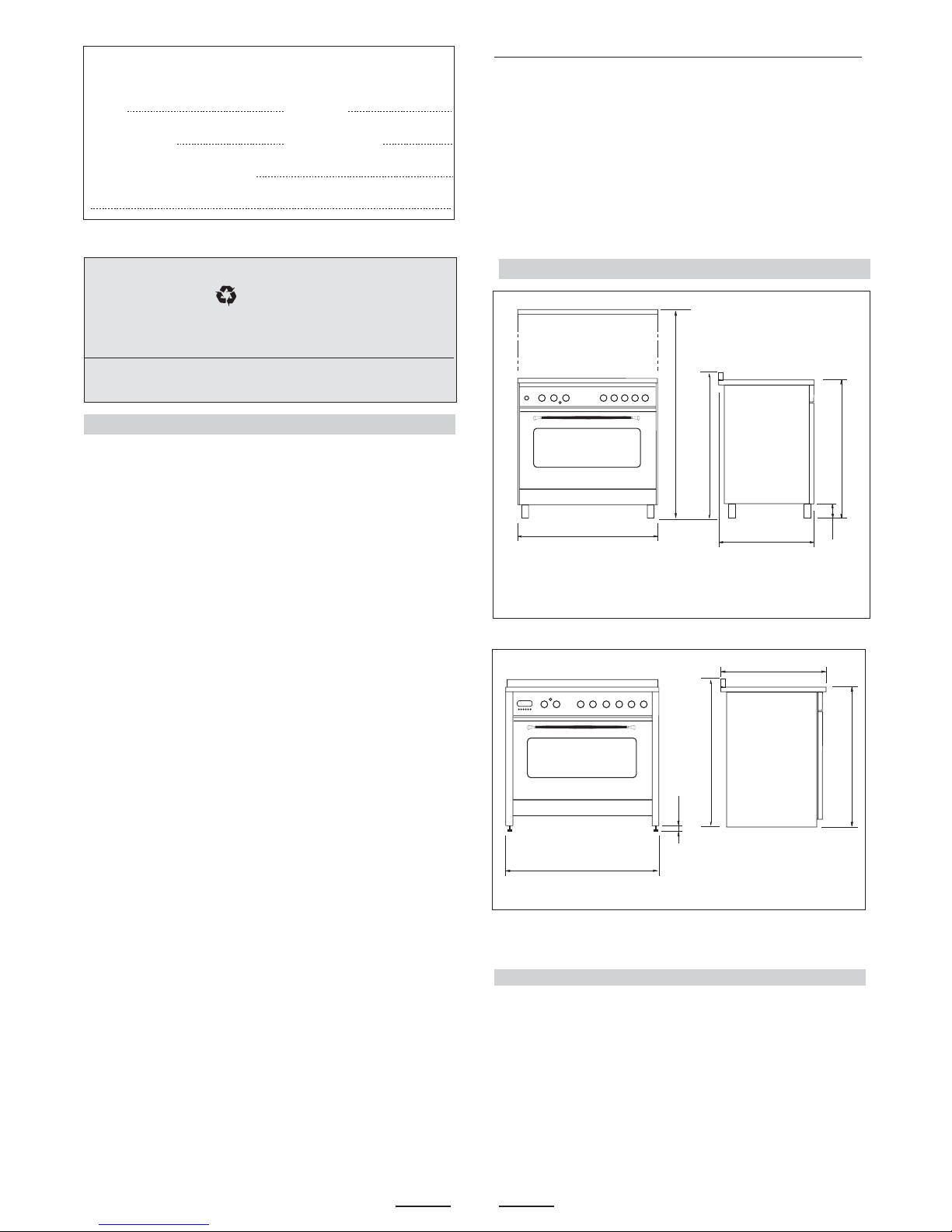
OVERALL DIMENSIONS
SECTION FOR THE QUALIFIED TECHNICIAN
WARNING -Accessible parts will become hot when in use.
To avoid burns and scalds children should be kept away.
X
1450/1500
600
h*
850/900
910/960
PROVISION FOR VENTILATION
INSTALLATION
The room where the Cooker is installed should have permanent
ventilation as follows:
Ventilation must be in accordance with AS5601/AG 601 - Gas
Installations. In general, the appliance should have adequate
ventilation for complete combustion of gas, proper flueing and to
maintain temperature of immediate surroundings within safe limits.
-
Do not install in a bed-sitting room, a bathroom or shower room.
If there is another fuel burning appliance in the same room, a
higher level of ventilation will be required, you should consults
" the safety requirements".
In addition to the above, during prolonged use, opening a window
in the same room is recommended. This will avoid the build up
of excessive moisture and condensation.
- WARNING:
A steam cleaner is not to be used cleaning this appliances.
- WARMING
DO NOT place inflammable materials or plastic utensils in the
warming drawer.
- WARNING -
In order to prevent accidental tipping of the appliance, for example
by a child climbing onto the open oven door, the stabilizing means
must be installed.
- WARNING
Before you use the appliance for the first time, check that the
plastic films protecting some parts (fascia panel, parts in stainless
steel, etc.) have been removed.
WHERE THIS APPLIANCE IS INSTALLED IN MARINE CRAFT
OR IN CARAVANS, IT SHALL NOT BE USED AS A SPACE
HEATER
DO NOT MODIFY THIS APPLIANCE.
- WARNING
This appliance is not intended for use by persons (including
children) with reduced physical, sensory or mental capabilities,
or lack of experience and knowledge, unless they have been
given supervision or instruction concerning use of the appliance
by a person responsible for their safety.
Children should be supervised to ensure that they do not play
with the appliance.
Young children and infirm persons should not be left
unsupervised in the vicinity.
Servicing shall be carried out only by authorised personnel.
DO NOT SPRAY AEROSOLS IN THE VICINITY OF THIS APPLIANCE
WHILE IT IS IN OPERATION.
Not for use in marine craft, caravans or mobile homes
unless each burner is fitted with a flame safeguard.
h* =
Adjustment
110 / 160
X
mod. 196 = 895 mm
X
mod. 190 = 895 mm
X
mod. 106 = 1000 mm
600
900
960
h* =
Adjustment
max 15 mm
1000
h*
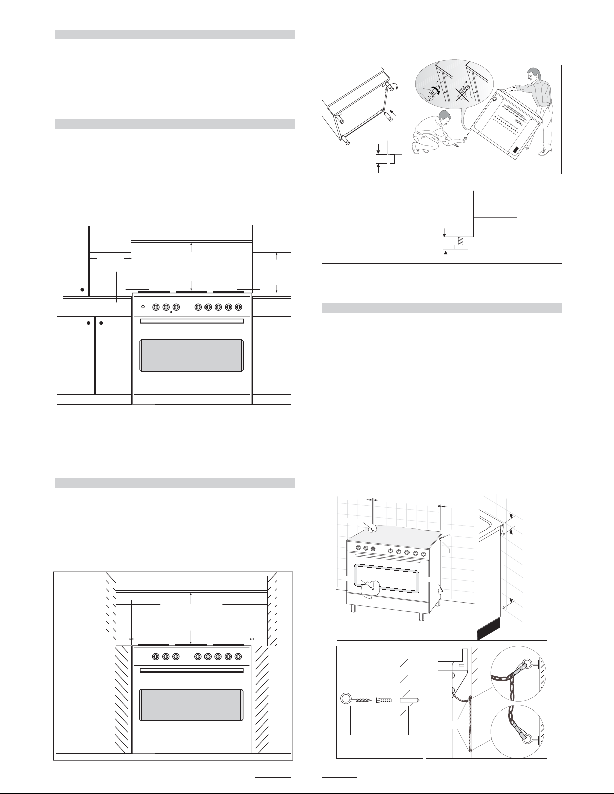
POSITIONING
Important: Fix the chain located next to the gas connection on
both sides of the cooker to the wall to prevent the cooker from
tilting. Both chains must be securely fixed.
Make sure that the wall surface behind the Cooker is noncombustable (will not catch fire).
Where a painted surface is adjacent, a fire retardent paint surface
is recommended. Wallpaper, wood, or fabric should not be used
behind or next to the cooker.
Any adjoining wall surface (side or rear) situated within 200mm
of any hob burner must be a suitable non-combustible material
from the edge for a height of 150mm for the entire length
of the cooker.
Any combustible construction above the cooker must be at least
650mm above the maintop. Ensure that a power and gas supply
are nearby. The Cooker should be located carefully so that the
heat produced by it has plenty of space to escape. The diagram
below shows an ideal configuration.
If the cooker is being fitted next to cupboards or adjoing wall
surfaces, which are within 200mm from the edge of the hob
burner and of a suitable non-combustible material as specified
Note:
The cooker is fitted with 4 legs for an eventual alignment in height
with the furniture
( fig. 1 A or 1 B according to the models ).
3
min.100 mm
min. 650 mm
min. 400 mm
"0" mm "0" mm
REG.
MAX
160mm
REG. MAX 15mm
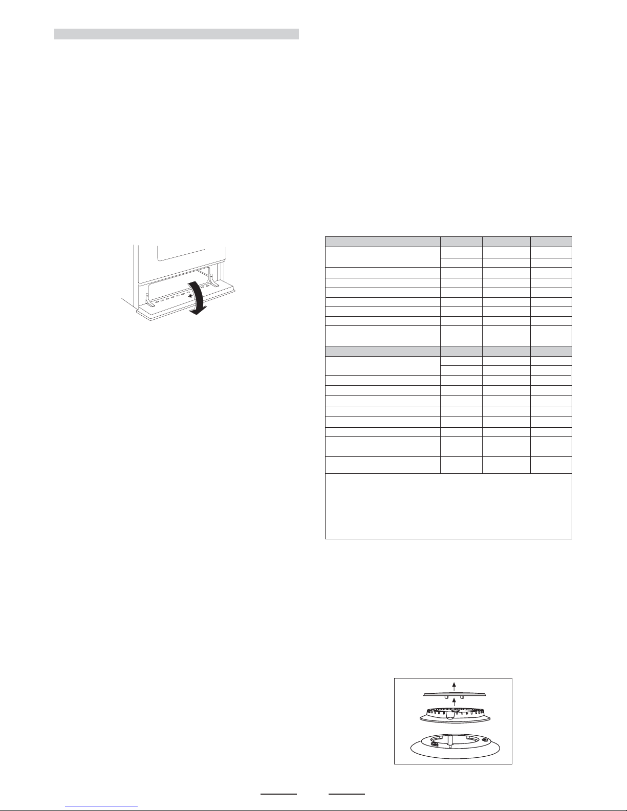
Clearances to combustible materials
No part of any adjoining wall surface can be made of combustible
materials. The protection of combustible materials
required by Clause 5.12.1.1 of AS5601-2004 is the fixing of 5 mm
thick ceramic tiles to the surface or attaching fire resistant
material to the surface and covering with sheet metal with a minimum
thickness of 0.4 mm.
Clearances to non- combustible materials
min. 650 mm
"0" mm "0" mm
min "60" mmmin "60" mm min "60" mm
non- combustible materials
non- combustible materials
in AS5601, then ensure that a distance of at least 6cm is left
between the edge of the cooker and the non-combustible
material. This gap is to allow plenty of space for the heat
produced by the cooker to escape on each side of the cooker.
min.10 mm
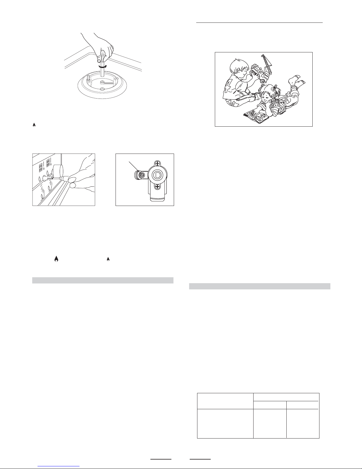
TO FIX THE COOKER TO THE REAR WALL
WARNING - For safety reasons and to prevent tipping of the appliance,
these stabilizing means must be installed.
The cooker is equipped with 2 chains fixed on each side at the rear of
the cooker near the top (see Fig. A). The chains are fitted with spring
clips which must be clipped to the screw eyes provided with the cooker.
Install the screw eyes as follows :
1. Drill four 6mm holes (position 1 - 2 - 3 - 4) in the wall
as in Fig. A.
2. Insert part R into the holes then screw in the screw eyes part
G see Fig. B.
Note: If the part provided is not suitable for the wall material please
use an appropriate device to ensure secure holding of the screw
eyes to the wall.
3. Bring the cooker near the wall and clip the chains on the
screw eyes as in Fig. C.
IMPORTANT: If the cooker is moved for any reason
(e.g. maintenance) resulting in the cooker being unclipped from the
wall, the cooker must be re-clipped to the wall at the completion of
the task.
If the cooker is placed on a base, measures have to be taken to prevent
it from slipping off the base.
OK NO
Fig. 1 A
Fig. 1 B
Fig. B
Fig. C
G
wall
wall
Fig. A
76 mm550 mm
G R Hole
55 mm
chain
Position
1
Position
2
55 mm
Position
3
Position
4
4
SPECIAL NOTE
After installation or any servicing operation, always ensure that
the appliance is gas sound and that the components are now
operating correctly. Items removed during servicing should be
replaced in the reverse order to their removal.
In order to change the work-top injectors, it is necessary to act as
follows:
- remove the grids
- remove burners
and flame-spreaders.
GAS CONNECTION
Should conform to gas utility regulations e.g. AS5601 Gas
installations; also refer to rangehood manufacturers
recommendations.
Check gas pressure, note the correct setting from the data plate
sealed inside the front appliance drawer .
This appliance from the factory suitable for NATURAL gas but, if
necessary, can be adjusted for U-LPG by authorised person.
*
IT IS RECOMMENDED THAT A SERVICE TAP AND UNION BE
FITTED ADJACENT TO THE APPLIANCE INLET TO FACILITATE
FUTURE SERVICING.
5 burner models: set the burner pressure to 1kPa for Natural Gas
and 2.75kPa for U-LPG with the wok burner operating a full rate.
For commissioning of the appliance with the Oara 97
regulator for Natural Gas, the test point pressure should
be 1.00kPa with all burners operating on HIGH.
Apply a manometer to the test nipple and reset the regulator if
necessary. Do not forget to replace the test nipple screw and to
leave the instructions book with the user.
VERY IMPORTANT FOR THE INSTALLER
Do not attempt to turn or stress threaded elbow of the manifold:
you risk damage to this part of the gas appliance which may void
the manufacturers warranty.
Before Leaving - Check all connections for gas leaks with soap
and water. DO NOT use a naked flame for detecting leaks. Ignite
all burners to ensure correct operation of gas valves, burners and
ignition. Turn gas taps to low flame position and observe stability
of the flame.
When satisfied with the cooker, please instruct the user on the
correct method of operation.
In case the appliance fails to operate correctly after all checks
have been carried out, refer to the authorised service provider in
your area.
GAS CONVERSION AND ADJUSTMENT
When used with natural gas all burners have been preset at our
factory and further adjustment should not be necessary. Conversion
kits to other gases are available from the place of purchase. Do
not attempt to fit the conversion kit yourself. Conversion to U-LPG
gas should only be carried out by an authorized technician.
GAS ADJUSTEMENTS
- change the injectors
- adjust the minimum flow
When converting from Natural Gas to U-LPG ensure that
the NG regulator is removed and replaced with the Test Point
Assembly. A gas regulator suitable for a supply pressure of 2.75kPa
should be part of the gas tank supply and should be adjusted with
the wok burner operating at maximum.
REPLACEMENT OF THE INJECTORS
When required to operate on other gas replace the injectors in
accordance with information referred to in chart below.
other relevant statutory code band regulations. If you have some
doubts, please contact the authorities for confirmation concerning
the characteristics of the gas and electricity output.
The appliance is generally preset for natural gas (so no other
adjustment is necessary) ensure regulator is fitted for N.G.
Ensure that all foreign matter has been cleared from the gas
supply line and also purge all air from the gas system. Connect
to regulator, tighten and check the installation to ensure no gas
leaks occur.
accordance with the manufacturers installation instructions,
relevant local fitting regulations, municipal building regulations,
the AS5601 code for gas burning appliances and equipment and
and 695mm from the floor (depends on adjustment of feet).
The appliance shall be installed by an authorized person in
For the adjustments to U-LPG please operate as specified in the
paragraph GAS CONVERSION AND ADJUSTMENT (pag 4).
The Gas Connection is male 1/2" BSP and is situated at the right
hand rear of the appliance, approximately 40mm from the side
This appliance can be connected with rigid pipe as specified in
AS5601 table 3.1 or with an AGA approved, Class B or D flexible
hose with 10mm I.D. and 1.2m max. length in accordance with
AS5601 for a 'high level connection'.
The hose should not be subjected to abrasion, kinking or permanent
deformation and should be able to be inspected along its entire
length. Unions compatible with the hose fittings must be used and
connections tested for gas leaks. The fixed consumer piping outlet
should be at approximately the same height as the cooker
connection point, pointing downwards and approximately 150mm
to the side of the cooker.
The hose should be clear of the floor when the cooker is in the
installed position.
Ensure that the chain prevents stress on the hose assembly when
the cooker is moved out of its normal operating position.
TA B. 1
Natural Gas 1.00 kPa
0.90 Auxiliary 4.0
1.20 Semi-rapid
7.1
1.50 Rapid 11.0
1.60 TC 12.5
U - LPG 2.75 kPa
0.53 Auxiliary 3.7
0.73 Semi-rapid 7.0
0.95 Rapid 11.7
1.00 TC 12.9
NG Regulator
LP Test point
adaptor
Regulator
1.55 TC 12.0
with GC & GL & YP pan supports
0.95 TC 12.0
1.50
fish 11.0
0.93
fish 11.4
with GE & GP pan supports
with GC & GE & GP & GL & GU pan supports
1.35 Rapid 9.1
with YP pan supports
with GE & GP & GL pan supports
1.45
fish 10.4
with YP pan supports
0.87 Rapid 10.2
Jet mm Ø Burners Power MJ/h
Jet mm Ø Burners Power MJ/h
with GC & GE & GP & GL & YP & GU
pan supports
NOTE:
GE = Enameled Steel pan supports
GL = Light Cast Iron pan supports
YP = Light Cast Iron pan supports (evolution)
GP = Heavy Cast Iron pan supports
0.80
fish 8.5
GC = Flat heavy cast iron pan supports
GU = Flat heavy cast iron pan supports
1.00 TC 1 12.7
1.63 TC1 12.7
with GC & GE & GP & GL & YP & GU
pan supports
with GC & GL & YP pan supports
with GE & GP pan supports
with GC & GE & GP & GL & GU pan supports
with YP pan supports
with GE & GP & GL pan supports
with YP pan supports
with GC & GE & GP & GL & YP & GU
pan supports
with GC & GE & GP & GL & YP & GU
pan supports
5
- change the injector (see Fig. C) and replace it with another one
suitable for the new type of gas (see tab. 1)
Fig. C
Z
Fig. 2BFig. 2A
MINIMUM FLOW ADJUSTMENT FOR HOB-TOP TAPS
In order to adjust the minimum flame setting proceed as follows:
switch the burner on, and set the knob at the minimum position
. Remove the knob from the tap, place a small bladed screwdriver
down the centre of the tap shaft (fig. 2A).
Attention: on taps with a security valve, the minimum adjusting
screw «Z» is on the body of the gas tap (fig. 2B).
Unscrew the adjusting screw in order to increase the flow or screw
it to decrease the flow.
The correct adjustment is obtained when the flame has a length
of about 3 or 4 mm.
For butane/propane gas, the adjusting screw must be screwed
in thigt.
Make sure that the flame does not go out turning quickly from the
max. flow to the minimum flow .
Refit the knob again.
2nd SECTION FOR THE USER
WARNING:
Children should be kept away while the oven or grill is in use
since accessible parts become hot.
- Do not use oven base panel as a shelf, make use of the oven
shelves.
- To avoid splattering and smoke, position collecting tray under
the grill with some water in it.
- Always turn pan handles to the side or to the back of the hob.
If they are left out into the room they can easily be hit or reached
by children, this knocking the pan off the hob.
- Dont let children sit down or play with the oven door. Do not
use the drop down door as a stool to reach above cabinets.
- Once your cooking is over make sure to close the main gas
supply.
WARNING
* This appliance is not intended for use by young children or
infirm persons without supervision.
* Young children should be supervised to ensure that they do
not play with the appliance.
BURNERS PANS
fl min. fl max
AUXILIARY 80 mm 160 mm
SEMI-RAPID 120 mm 200 mm
RAPIDE 200 mm 230 mm
TRIPLE CROWN 230 mm 260 mm
- 1 Minute Tour -
Be safe
Please read the rest of the instruction book which contains
important information to help you use the appliance safely and
efficiently.
Gas and Electricity on
Make sure that the gas supply is turned on and that the appliance
is plugged in and switched on. The ignitor needs electricity.
In case there is no electric current, the burner can also be lighted
using a match.
It is recommended that pans suitable to the size of the burner
should be used as follows:
- WARNING -
In order to prevent accidental tipping of the appliance, for example
by a child climbing onto the open oven door, the stabilizing means
must be installed.
ELECTRICAL CONNECTION
The appliance must be installed by a suitably qualified person in
accordance with these instructions and with the requirements of
the Australian Wiring Rules AS/NZS 3000.
Fixed wired installations are to be provided with suitable isolation
means in accordance with the said rules.
Any plug socket installed for the purpose of connecting the appliance
to supply must be readily accessible when the appliance is installed.
Before making the connection, make sure that:
1) the safety circuit-breaker and the electrical system are able to
withstand the load of the appliance (see nameplate).
2) the power supply system has an earth connection in good
working order in accordance with the regulations in force;
IMPORTANT
The wires in the mains lead are coloured in accordance with the
following code:
GREEN & YELLOW.........................................................EARTH
BLUE...........................................................................NEUTRAL
BROWN ...............................................................................LIVE
Electric power ..1,5 mm2 3 core cable (15 amp. Fuse required).
Should conform to local authority requirements.
Also refer to rangehood manufacturers recommendations.
This appliance is supplied with a plug & cord, simply plug into a
3 pin household socket outlet witch is properly earthed.
WARNING: THIS APPLIANCE MUST BE EARTHED.
The flexible mains lead and plug must not be in contact with hot
surfaces.
 Loading...