

Page 1

Installation, Use & Maintenance
Instruction Manual
Model:
E1200ISLSX
bringing the best of Italian quality to Australia
Page 2

2
Page 3

3
The symbol on the product or on its packaging indicates that this product may
not be treated as household waste. Instead it shall be handed over to the applicable collection point for the recycling of electrical and electronic equipment. By ensuring this product is disposed of correctly, you will help prevent
potential negative consequences for the environment and human health, which
could otherwise be caused by inappropriate waste handling of this product.
For more detailed information about recycling of this product, please contact
your local city oce, your household waste disposal service or the shop where you purchased the product. This appliance is marked according to the European directive 2002/96/EC on waste electrical and electronic equipment (WEEE).
GB
Page 4

- CONTENTS GB
Warnings 5
Uses 6
Installation 6
Working 7
Maintenance 7
4
Page 5

* The appliance is not intended for use by young children or inrm persons without
supervision. Young children should be supervised to ensure they do not play with the
appliance.
* The cooker surface and the inferior part of the cooker hood must be at a minimun distance of 65 cm.
* The air sucked can’t be conveyed through or into a duct used to let out fumes from
appliances fed by energy other than electric power (eg. centralized heating, radiators,
water-heaters, etc.).
* To evacuate the air outlet, please comply with the pertaining rules given by competent
authorities.
* Provide the room with an adequate aeration when a cooker hood and appliances fed by
energy other than electric power (gas-, oil-, or coal- stoves, etc.) are used simultaneously.
The cooker hood, when evacuating the sucked air, could generate a negative pressure in the
room- which can’t exceed the limit of 0.04 mbar, in order to avoid the suck of exhausts deriving from the heat-source. Therefore the room should be provided with air-intakes to allow
a costant ow of fresh air.
*The air must not be discharged into a ue that is used for exhausting fumes from appliances burning gas or other fuels (not applicable to appliances that only discharge the air back
into the room).
If the rating lable in the cooker-hood shows the symbol , the appliance is built in class
II° and it does not need any earth connection.
If the rating lable in the cooker-hood does not show the symbol , the appliance is built
in class I° and it needs the earth connection.
* When performing the electrical connections on the appliance, please make sure that the
current-tap is provided with earth connection and that voltage values correspond to those
indicated on the label placed inside the appliance itself.
* Before carrying out any cleaning or maintaining operations, the appliance needs to be removed from the electric grid.
If the appliance is not provided with a non-separable exible cable and plug, or with another
device ensuring omnipolar disconnections from the grid, with an opening distance between
the contacts of at least 3 mm, then such disconnecting devices must be supplied within the
xed installation.
If the appliance is endowed with a supply cord and a plug, the appliance has to be put in a
place where the plug can be reached easily.
* The use of materials which can burst into ames should be avoided in close proximity
of the appliance. When frying, please pay particular attention to re risk due to oil grease. Being highly inammable, fried oil is especially dangerous. Do not use uncovered
electric grills. In order to avoid possible re risk, all instructions for grease-lter cleaning and for removing eventual grease deposits should be strictly followed.
- WARNINGS GB
5
Page 6

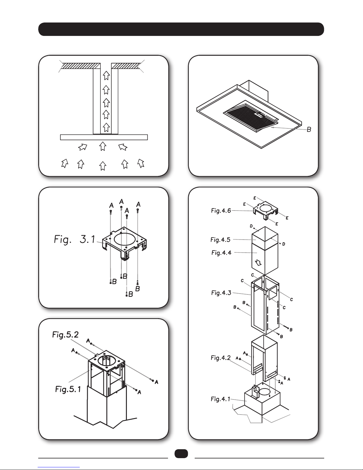
* In its sucking version (Fig. 1), fumes are directly conveyed outside, through an evacuation
duct connected with the superior part of the wall or the ceiling. Both coal lter and air deector
are not necessary in this case.
- USES GB
6
* Before installing the appliance, in order not to damage the appliance itself, the metal grease lter should be removed. Such lter can be removed by pushing the special lter handle
toward the back side of the cooker hood and turning it downwards so to unfasten it from its
slot (Fig. 2).
Attention: at least two people are needed to perform the installation.
Before xing the hood, place the electric feeding properly into the ornamental pipe and place
a hole for air evacuation in case of a sucking version.
* Suction model
Place the upper plate (Fig. 3.1) on the ceiling. Drill 4 holes, 8 mm each, just next to the slots.
Insert the plastic dowels into the holes (Fig. 3A) and screw up the plate on the ceiling (Fig. 3B).
Then fasten the lower structure (Fig. 4.2) on the hood by making its holes and the metricthread screws welded on the fan support coincide (Fig. 4.1). Insert the washers and nuts provided (Fig. 4.2) and screw with an appropriate tool.
Connect the drainpipe to the power unit nozzle and x securely with a hose clamp.
Insert the upper structure (Fig. 4.3) into the lowest one and adjust its height as required by
matching it with the cooking top’s minimum height. Tighten the two structures securely with
the screws provided (Fig. 4.3-B).
Insert the two extension tubes (Fig. 4.4 & Fig. 4.5) from above the two structures by making
them come down to the appropriate hood seat. Lift the hood together with the structure and
the extension tubes to make the four springs (Fig. 4.6-E) hook to the slots (Fig. 4.3-C). Then
tighten the two elements securely (Fig. 5.1 & Fig. 5.2) with the safety screws (Fig. 5.2-A) and
connect the hood tube to the drain hole.
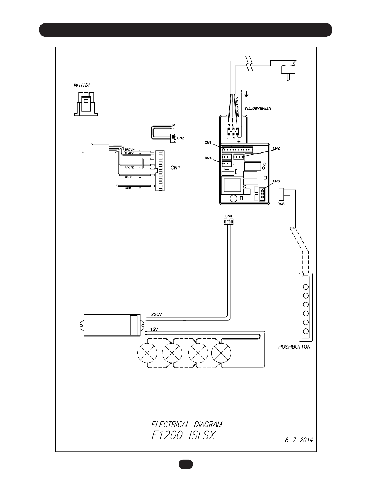
Make the electrical connections.
Lift the upper tube (Fig. 4.5) up to the ceiling and insert the two self-tapping screws (Fig.
4.5-D).
Warning!
Before connecting the exible exhausting pipe to the motor, make sure the stop valve, which
is on the air outlet of the motor, can swing.
Warning: Failure to install the screws or xing device in accordance with these instructions
may result in electrical hazards.
- INSTALLATION GB
This appliance is not intended for use by persons (including children) with reduced physical,
sensory or mental capabilities, or lack of experience and knowledge, unless they have been
given supervision or instruction concerning use of the appliance by a person responsible for
their safety. Children should be supervised to ensure that they do not play with the appliance.
Do not ambè under the range hood.
CAUTION: Accessible parts may become hot when used with cooking appliances.
Page 7
7
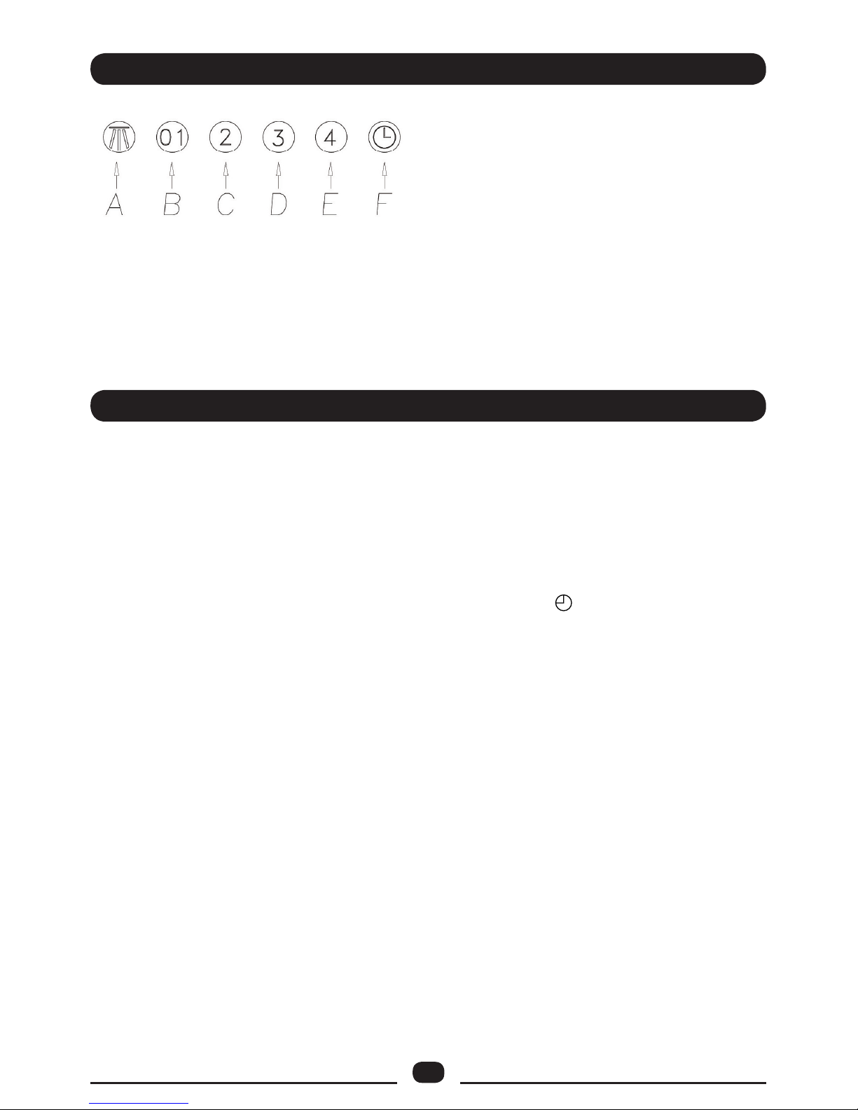
A: Light switch on/o
B: Motor switch on/o (1st rate level)
C: 2nd rate level switch
D: 3rd rate level switch
E: 4th rate level switch
F: 10 - minutes timer
- WORKING GB
* An accurate maintenance guarantees good functioning and long-lasting performance.
* Particular care is due to the grease lter panel. It can be removed by pushing its special han-
dle toward the back-side of the cooker hood and turning the lter downwards so to unfasten
it from its slot (Fig. 2).
To insert the lter just perform the opposite operation.
After 30 hours working, the push button control panel will signal the saturation of the grease
lter by lighting all the buttons. Press the timer button to reset .
The grease lter needs cleaning by regular hand-washing or in dishwasher every two months
at least or depending on its use.
There is a re risk if cleaning is not carried out in accordance with these instructions.
* To clean the appliance itself tepid water and neutral detergent are recommended, while
abrasive products should be avoided. For steel appliances specialized detergents are recommended (please follow the instructions indicated o the product itself to obtain the desired
results).
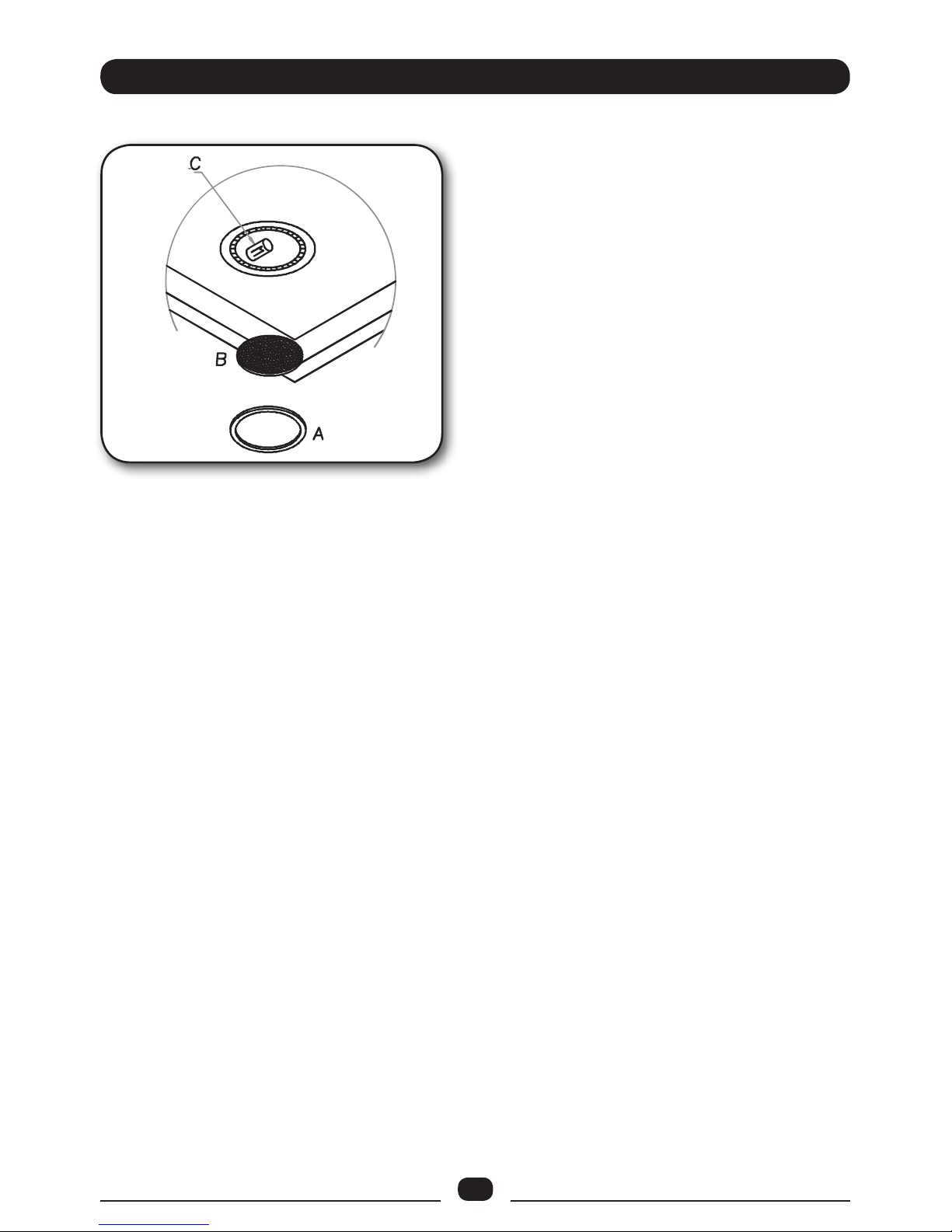
* To replace the halogen lamps, remove rst the glass-blocking ring (Fig. 6A), by levering
with a screw-driver and thus removing the opaque glass (Fig. 6B) - when performing this
operation hold the opaque glass carefully. Remove the lamp (Fig. 6C) without touching it with
uncovered hands. Replace it with another lamp of the same kind.
If the supply cord is damaged, it must be replaced by the manufacturer, its service agent or
similarly qualied persons in order to avoid a hazard.
- MAINTENANCE GB
Page 8
8
GB
Page 9
9
GB
1 2
3
4
5
Page 10
10
GB
6
Page 11

11
Page 12

00000000000 - GM 10/14
 Loading...