

Euresys PICOLO Tetra, PICOLO Tetra-RC, PICOLO Tetra-X, PICOLO Tetra-X-RC, PICOLO Jet-X User Manual
...
EureCard PICOLO series
PICOLO Tetra, PICOLO Tetra-RC,
PICOLO Tetra-X, PICOLO Tetra-X-RC,
PICOLO Jet-X, PICOLO Jet-X-RC
VEB, VEB 12, MIO
Manual
Copyright © 2005 Euresys s.a.
Avenue du Pré-Aily, 14
Phone +32 4 367 72 88 • Fax +32 4 367 74 66
B-4031 Angleur Belgium
E-mail: info@euresys.com
Web site: www.euresys.com
This book is part of the documentation
provided with MultiCam.
For more information, refer to the
documentation provided in the latest
EureCard Picolo series Manual
Liège Science Park
MultiCam release.
Tome 2
January 2005

Copyright © 2005 Euresys s.a.
EURESYS S.A. shall retain all property rights,
Printed in Belgium.
WARNING
title and interest in the hardware or the software,
documentation and trademarks of EURESYS S.A.
All the names of companies and products
mentioned in the documentation may be
the trademarks of their respective owners.
The licensing, use, leasing, loaning, translation,
reproduction, copying or modification of the hardware
or the software, marks or documentation of EURESYS S.A.
contained in this book, is not allowed without prior notice.
EURESYS S.A. may modify the product specifications
or change the information given in this documentation
at any time, in its discretion, and without prior notice.
EURESYS S.A. shall not be liable for any loss of
or damage to revenues, profits, goodwill, data,
information systems or other special, incidental,
indirect, consequential or punitive damages of
any kind arising in connection with the use of
the hardware or the software of EURESYS S.A.
or resulting of omissions or errors in this book.

Table of contents
3
Table of Contents
Part I. Picolo Tetra Product Description............................................................7
1. Product appearance............................................................................................7
2. PCI requirements.................................................................................................8
3. Connectors ..........................................................................................................9
4. Features .............................................................................................................10
5. Picolo Tetra block diagram...............................................................................11
6. Picolo Tetra and Tetra-RC standard compliance............................................12
Part II. Picolo Tetra-X Product Description .................................................... 13
1. Product appearance..........................................................................................13
2. PCI requirements...............................................................................................14
3. Connectors ........................................................................................................15
4. Features .............................................................................................................16
5. Picolo Tetra-X block diagram ........................................................................... 18
6. Picolo Tetra-X and Tetra-X-RC standard compliance ....................................19
Part III. Picolo Jet-X Product Description....................................................... 21
1. Product appearance..........................................................................................21
2. PCI requirements...............................................................................................22
3. Connectors ........................................................................................................23
4. Features .............................................................................................................24
5. Picolo Jet-X block diagram...............................................................................26
6. Picolo Jet-X and Jet-X-RC standard compliance............................................27
Part IV. Picolo RC Product Description........................................................... 29
1. Common characteristics of RC boards ........................................................... 29
2. Product appearance of Tetra-RC .....................................................................30
3. Product appearance of Tetra-X-RC..................................................................31
4. Product appearance of Jet-X-RC .....................................................................32
5. PCI requirements...............................................................................................33
6. Connectors ........................................................................................................33
7. 75 ohms solder bridges .................................................................................... 34
8. Block diagrams..................................................................................................35
9. Video input routing ...........................................................................................38
Part V. VEB and VEB 12 Product Description................................................ 41
1. Product appearance..........................................................................................41
2. Connectors ........................................................................................................43
3. Features .............................................................................................................44
4. Video input/output routing ...............................................................................45
5. VEB and VEB 12 standard compliance ...........................................................48
Part VI. MIO Module Product Description ...................................................... 49
1. Product appearance..........................................................................................49
2. Connectors ........................................................................................................50
3. Features .............................................................................................................51
4. MIO standard compliance................................................................................. 52

Table of contents
Part VII. Hardware Installation Procedure ...................................................... 53
1. Warnings............................................................................................................53
2. Hardware installation procedure......................................................................54
3. Picolo RC series hardware installation ...........................................................56
4. Input Video Expansion Bracket hardware installation...................................57
5. Output Video Expansion Bracket hardware installation................................57
6. MIO hardware installation................................................................................. 58
Part VIII. MultiCam Installation Guide ............................................................. 61
1. Hardware requirements ....................................................................................61
2. Linux installation...............................................................................................61
3. Windows installation.........................................................................................62
Part IX. Technical Specifications .................................................................... 63
1. Technical specifications for all Picolo products ............................................63
2. Picolo Tetra series technical specifications ................................................... 65
3. Picolo Jet-X technical specifications ..............................................................67
4. MIO technical specifications ............................................................................69
4
5
Contact Us
Euresys
General information: info@euresys.com
Contact Us
Web site: www.euresys.com
America Asia Japan Europe
Euresys inc. Euresys Pte. Ltd.
500 Park Boulevard
Suite 525
Itasca, Illinois 60143,
U.S.A.
America
Toll free:
+1 866-EURESYS
Phone:
+1 630 250 2300
Fax:
Phone:
Fax:
Phone:
Fax:
+1 630 250 2301
+65 6748 0085
+65 6841 2137
+81 3 5447 1256
+81 3 5447 0529
Asia
Japan
Euresys s.a. Japan Euresys s.a.
Representative Office Corporate Headquarters
627A Aljunied Road
#08-09 BizTech Centre
Singapore 389842
Technical support: support.usa@euresys.com
Technical support: support.asia@euresys.com
Technical support: support.asia@euresys.com
AIOS Hiroo Building 8F,
Hiroo 1-11-2,
Shibuya-ku,
Tokyo 150-0012,
Japan
Avenue du Pré-Aily, 14
B-4031 Angleur,
Belgium
Europe
Phone:
+32 4 367 72 88
Fax:
+32 4 367 74 66
Technical support: support.europe@euresys.com

This page is intentionally left blank.
Picolo Tetra Product Description
Part I. Picolo Tetra Product Description
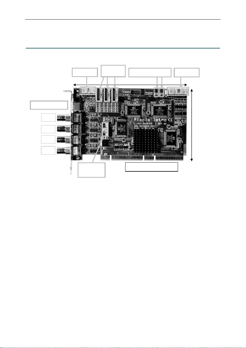
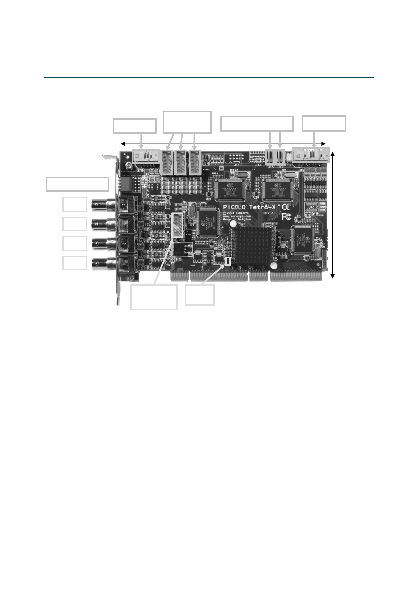
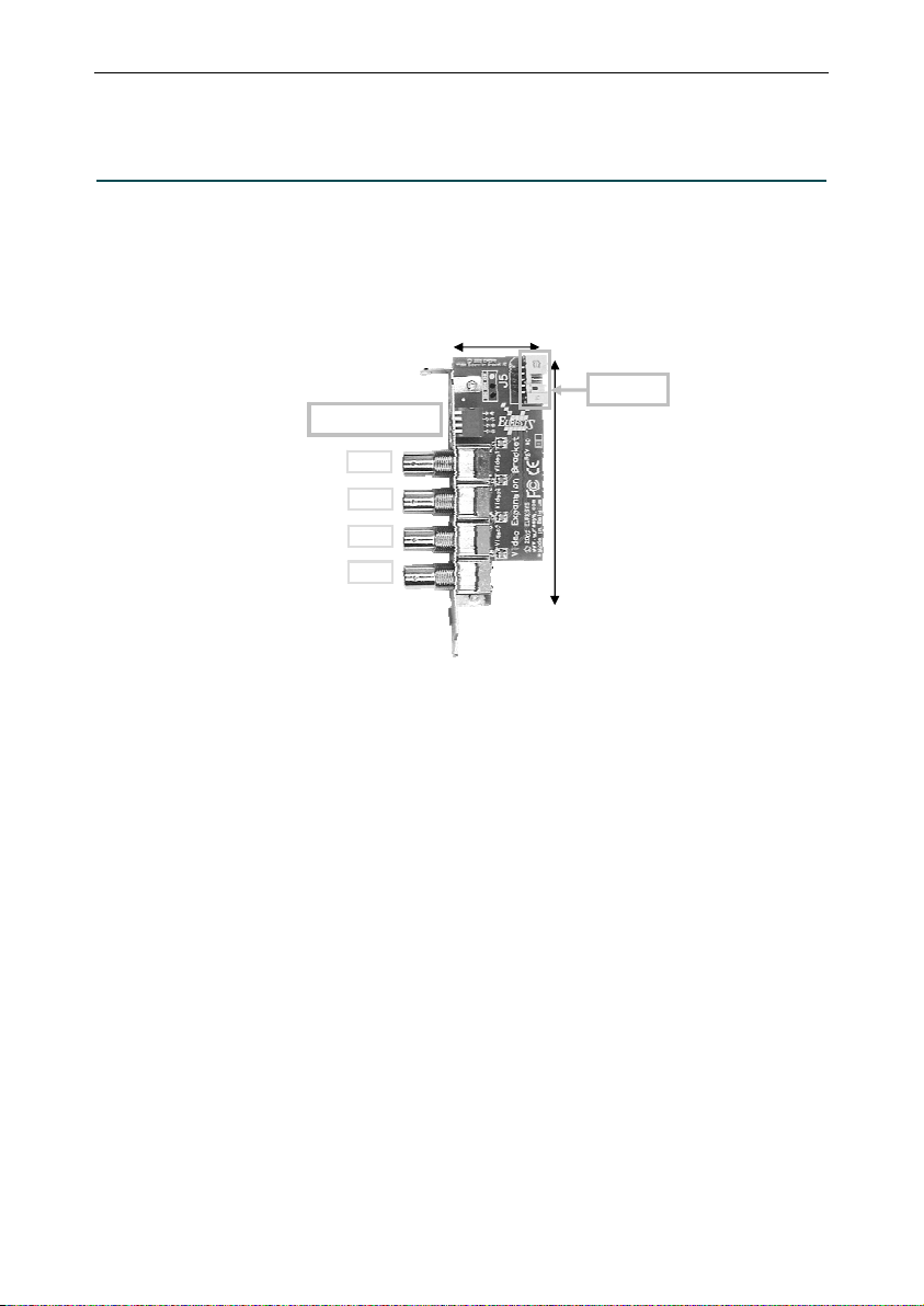
1. Product appearance
MIO LINK
75 ohms switches
VEB LINK
(video in)
1 2 3
PC reset headers
168 mm / 6.61 in
Digital IO
VID1
VID2
VID3
VID4
VEB LINK
(video out)
Picolo Tetra is a 64-bit, 66 MHz PCI capture board including four color video digitizers. This Picolo board acquires four
real-time video signals in parallel. It may be extended to manage 16 cameras.
Expansion accessories are identical for Picolo Tetra series. Video Expansion Bracket and Video Expansion Bracket 12
are presented in part V. MIO module is described in part VI.
Wide PCI bus connector
107 mm /
4.21 in
7

Picolo Tetra Product Description
8
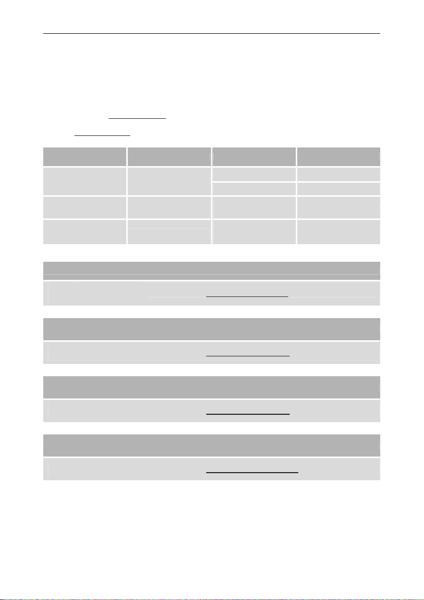
2. PCI requirements
PCI stands for "Peripheral Component Interconnect" and refers to standardized means to install an add-on board
inside a computer.
Picolo Tetra is a medium-size PCI card to be inserted in a standard PCI slot inside a PC. The PCI edge connector is
compliant with the official PCI specification, revision 2.2. It is 64-bit wide, operates at 66 MHz maximum, and supports
3.3 V or 5 V signaling systems.
Picolo Tetra can be used in a 33 MHz or 66 MHz PCI slot and using the PCI slot with 32-bit or 64-bit.
For more information, see “PCI Bus Variation” application note.
Picolo Tetra uses the +5 V, +12 V and -12 V power supply rails provided by the PCI bus.
Typical electrical consumption is as follows:
PCI power rail Current Power
+5 V 1.3 A 6.5 W
+12 V 0.12 A 1.44 W
-12 V 5 mA 0.06 W
Total power consumption is typically 8 W.
Notes:
1. Video Expansion Bracket and Video Expansion Bracket 12 do not consume any power.
2. These PCI characteristics do also apply to Picolo Tetra-RC.
Picolo Tetra Product Description
9
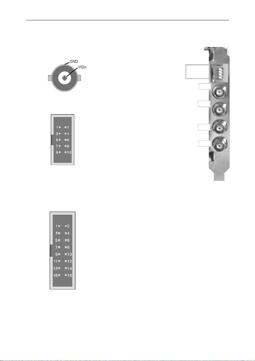
3. Connectors
3.1. “VIDn” connector
3.2. “VEB LINK” connectors
VID1
VID2
VID3
VID4
Presence
Notes:
1. Each video differential pair is composed of VIDn and GNDn, both connected to digitizer n
where n = 1, 2, 3 or 4.
2. To inform the system of the Video Expansion Bracket existence, simply short-circuit pin 9
“Presence” with pin 10 “Dig. GND”, digital ground of a Picolo Tetra.
GND1
GND2
GND3
GND4
Dig. GND
VID1, VID2, VID3 and VID4 are selectable
color or monochrome composite inputs.
They are terminated with removable
75 ohms loads.
To modify the 75 ohms termination setting,
see “75 ohms switches”.
Each 10-pin header connector allows to connect one
Video Expansion Bracket with a Picolo Tetra.
Three VEB LINK connectors are used to add video
inputs to a Picolo Tetra. For more details, see “Video
input routing”.
One VEB LINK connector is used for video outputs of
digitalized images. For more details, see “Video output
routing”.
75 ohms
switches
VID1
VID2
VID3
VID4
1 2 3 4
3.3. “Digital IO” connector
Reserved
IO1
IO3
IO5
IO7
IO9
IO11
IO13
GND
IO2
IO4
IO6
IO8
IO10
IO12
GND
The “Digital IO” internal connector on the Picolo Tetra has 13
TTL I/O lines that can be used by the MultiCam software
driver as inputs, outputs or trigger lines.
Other Euresys video capture boards use the same connector.
3.4. “MIO LINK” connector
Using flat cables, this 10-pin header connector allows to interconnect a Picolo Tetra to MIO modules.
For more details, see “MIO hardware installation” in part VII.
Picolo Tetra Product Description
4. Features
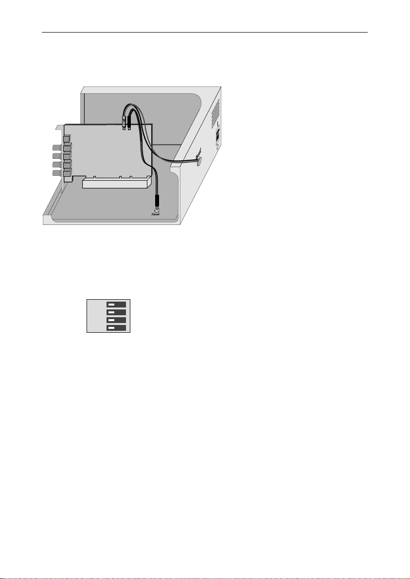
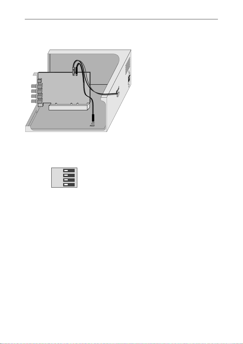
4.1. PC reset headers
Picolo
Picolo
Tetra
64-bit board
Tetra
PCI slot
The two "PC reset headers" are equivalent.
See also topic "Using the watchdog" in the electronic documentation.
4.2. 75 ohms switches
1 2 3 4
OFF ON
The switch n controls the 75 ohms termination of the
corresponding VIDn input, where n = 1, 2, 3 or 4.
In the factory configuration, all video terminations are active.
Therefore, all switches are closed (ON position).
To remove the termination, set the switch to OFF position.
A reset cable can be connected directly to a "PC
reset header". The watchdog uses a static switch
with an ON resistance of about 35 ohms. The
polarity at the switch input doesn't matter.
In the drawing is illustrated the control of PC reset
by button or by the Picolo Tetra. The switch can
also be used for other purposes than resetting the
computer: for example, it can activate an alarm.
10
Picolo Tetra Product Description
V
V
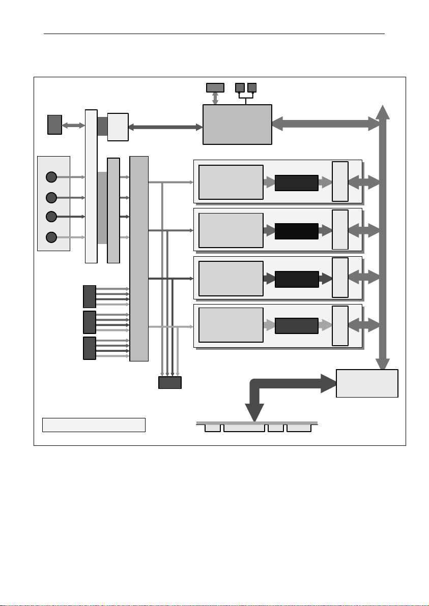
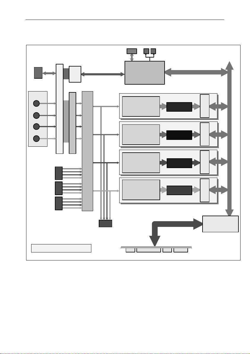
5. Picolo Tetra block diagram
Digital IO
VID 1
VID 2
VID 3
VID 4
Connectors on bracket
Electromagnetic compatibility network
EB LINK
(video in)
1
2
3
MIO LINK
PIO
Parallel
interface
PCI control
Digitizer 1
with color decoding,
scaling,
format conversion
Video
Common-mode noise removal
Digitizer 2
with color decoding,
scaling,
format conversion
Digitizer 3
with color decoding,
scaling,
format conversion
PC reset
headers
FIFO buffer 1
630 bytes
FIFO buffer 2
630 bytes
FIFO buffer 3
630 bytes
PCI
PCI
interface
interface
Embedded PCI bus
PCI
interface
Quadruple 4-to-1 analog router
Digitizer 4
with color decoding,
scaling,
format conversion
FIFO buffer 4
630 bytes
PCI
interface
Transparent
PCI bridge
Picolo Tetra Block Diagram
EB LINK
(video out)
PCI connector
64 bits, 66 MHz
Video input/output routing
The detailed routing is presented in part V, “VEB and VEB12 Product Description”.
11

Picolo Tetra Product Description
6. Picolo Tetra and Tetra-RC standard compliance
This equipment has been tested and found to comply with the limits for a Class B digital device, pursuant to Part 15 of
the FCC Rules.
These limits are designed to provide reasonable protection against harmful interference in a residential installation or
when the equipment is operated in a commercial environment.
This equipment generates, uses and can radiate radio frequency energy and, if not installed and used in accordance
with the instructions, may cause harmful interference to radio communications. However, there is no guarantee that
interference will not occur in a particular installation.
If this equipment does cause harmful interference to radio or television reception, which can be determined by turning
the equipment off and on, the user is encouraged to try to correct the interference by one or more of the following
measures:
• Reorient or relocate the receiving antenna.
• Increase the separation between the equipment and receiver.
• Connect the equipment into an outlet on a circuit different from that to which the receiver is connected.
• Consult the dealer or an experienced radio/TV technician for help.
This equipment has been tested and found to comply with EN55022/CISPR22 and EN55024/CISPR24. To meet EC
requirements, shielded cables must be used to connect a peripheral to the card. This product has been tested in a
typical class B compliant host system. It is assumed that this product will also achieve compliance in any class B
compliant unit.
Notice for USA
Compliance Information Statement (Declaration of Conformity Procedure) DoC
FCC Part 15
Notice for Europe
This product is in conformity with the Council Directive 89/336/EEC amended by
92/31/EEC and 93/68/EEC
Notice for Europe
Standard EN50130-4, immunity requirements for components of fire, intruder and
social alarm systems
Concerning video inputs, this equipment has been tested and found to comply with the following tests described in
EN50130-4:
• § 10, radiated RF immunity ;
• § 11, conducted RF immunity ;
• § 12, fast transient immunity.
12
Picolo Tetra-X Product Description
Part II. Picolo Tetra-X Product Description
1. Product appearance
MIO LINK
75 ohms switches
VEB LINK
(video in)
1 2 3
PC reset headers
168 mm / 6.61 in
Digital IO
VID1
VID2
VID3
VID4
VEB LINK
(video out)
Picolo Tetra-X includes:
• A PCI-X bridge that doubles the throughput compared with Picolo Tetra. The usage of a PCI-X slot is
mandatory to achieve this performance.
• An optimized internal PCI bus between digitizers and PCI-X bridge.
Picolo Tetra-X can be used in PCI-X 66MHz, 100 MHz or 133 MHz slots. It also works in standard PCI slots, 32-bit or
64-bit, up to 66 MHz, 3.3 V or 5 V.
Starting with board revision A1_1, the PCI-X jumper is removed.
Expansion accessories are identical for Picolo Tetra series. Video Expansion Bracket and Video Expansion Bracket 12
are presented in part V. MIO module is described in part VI.
PCI-X
jumper
PCI-X bus connector
107 mm /
4.21 in
13

Picolo Tetra-X Product Description
2. PCI requirements
PCI stands for "Peripheral Component Interconnect" and refers to standardized means to install an add-on board
inside a computer.
Picolo Tetra-X is a medium-size PCI card to be inserted in a PCI-X slot inside a PC. The PCI edge connector is
compliant with the official PCI specification, revision 2.3 and PCI-X addendum revision 1.0. It is 64-bit wide, operates
at 133 MHz maximum, and supports 3.3 V or 5 V signaling systems.
Picolo Tetra-X can be used in a 66MHz, 100 MHz or 133 MHz PCI-X slot.
Picolo Tetra-X can be used in a 33 MHz or 66 MHz PCI slot and using the PCI slot with 32-bit or 64-bit.
For more information, see “PCI Bus Variation” application note.
Picolo Tetra-X uses the +5 V, +12 V and -12 V power supply rails provided by the PCI bus.
Typical electrical consumption is as follows:
PCI power rail Current Power
Total power consumption is typically 9 W.
Notes:
1. Video Expansion Bracket and Video Expansion Bracket 12 do not consume any power.
2. These PCI characteristics do also apply to Picolo Tetra-X-RC.
+5 V 1.5 A 7.5 W
+12 V 0.12 A 1.44 W
-12 V 5 mA 0.06 W
14

Picolo Tetra-X Product Description
3. Connectors
3.1. “VIDn” connector
3.2. “VEB LINK” connectors
VID1
VID2
VID3
VID4
Presence
Notes:
1. Each video differential pair is composed of VIDn and GNDn, both connected to digitizer n
where n = 1, 2, 3 or 4.
2. To inform the system of the Video Expansion Bracket existence, simply short-circuit pin 9
“Presence” with pin 10 “Dig. GND”, digital ground of a Picolo Tetra-X.
GND1
GND2
GND3
GND4
Dig. GND
VID1, VID2, VID3 and VID4 are
selectable color or monochrome
composite inputs. They are
terminated with removable 75 ohms
loads.
To modify the 75 ohms termination
setting, see “75 ohms switches”.
Each 10-pin header connector allows to connect
one Video Expansion Bracket with a Picolo
Tetra-X.
Three VEB LINK connectors are used to add
video inputs to a Picolo Tetra-X. For more
details, see “Video input routing” in part V.
One VEB LINK connector brings back the 4
video signals being digitized. For more details,
see “Video output routing” in part V.
75 ohms
switches
1 2 3 4
VID1
VID2
VID3
VID4
3.3. “Digital IO” connector
Reserved
IO1
IO3
IO5
IO7
IO9
IO11
IO13
GND
IO2
IO4
IO6
IO8
IO10
IO12
GND
The “Digital IO” internal connector on the
Picolo Tetra-X has 13 TTL I/O lines that can
be used by the MultiCam software driver as
inputs, outputs or trigger lines.
Other Euresys video capture boards use the
same connector.
3.4. “MIO LINK” connector
Using flat cables, this 10-pin header connector allows to interconnect a Picolo Tetra-X to MIO modules.
For more details, see “MIO hardware installation” in part VII.
15
Picolo Tetra-X Product Description
4. Features
4.1. PC reset headers
Picolo
Picolo
Picolo
Tetra
64-bit board
Tetra-X
The two "PC reset headers" are equivalent.
See also topic "Using the watchdog" in the electronic documentation.
4.2. 75 ohms switches
Tetra
PCI slot
1 2 3 4
OFF ON
The switch n controls the 75 ohms termination of the
corresponding VIDn input, where n = 1, 2, 3 or 4.
In the factory configuration, all video terminations are active.
Therefore, all switches are closed (ON position).
To remove the termination, set the switch to OFF position.
A reset cable can be connected directly to a "PC
reset header". The watchdog uses a static switch
with an ON resistance of about 35 ohms. The
polarity at the switch input doesn't matter.
In the drawing is illustrated the control of PC reset
by button or by the Picolo Tetra. The switch can
also be used for other purposes than resetting the
computer: for example, it can activate an alarm.
16
Picolo Tetra-X Product Description
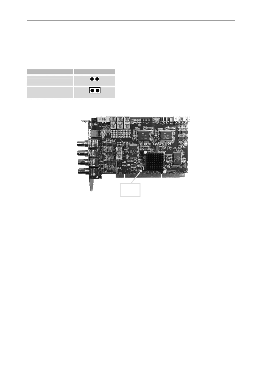
4.3. PCI-X jumper
Picolo Tetra-X is compatible with all PCI and PCI-X slots. Initial production boards (rev. A1_0) include a PCI-X jumper.
If present, the factory setting of this jumper is shorted.
Remove the PCI-X jumper if you intend to insert Picolo Tetra-X in a conventional PCI slot.
PCI slot category PCI-X jumper
Conventional PCI
PCI-X
open
shorted
PCI-X
jumper
17
V
V
Picolo Tetra-X Product Description
5. Picolo Tetra-X block diagram
Digital IO
VID 1
VID 2
VID 3
VID 4
Connectors on bracket
Electromagnetic compatibility network
EB LINK
(video in)
1
2
3
MIO LINK
PIO
Parallel
interface
Video
Common-mode noise removal
PCI control
Digitizer 1
with color decoding,
scaling,
format conversion
Digitizer 2
with color decoding,
scaling,
format conversion
Digitizer 3
with color decoding,
scaling,
format conversion
PC reset
headers
FIFO buffer 1
630 bytes
FIFO buffer 2
630 bytes
FIFO buffer 3
630 bytes
PCI
PCI
PCI
interface
interface
interface
Embedded PCI bus
Quadruple 4-to-1 analog router
Digitizer 4
with color decoding,
scaling,
format conversion
FIFO buffer 4
630 bytes
PCI
interface
Transparent
PCI-X bridge
Picolo Tetra-X Block Diagram
EB LINK
(video out)
PCI-X connector
64 bits, 133 MHz
Video input/output routing
The detailed routing is presented in part V, “VEB and VEB12 Product Description”.
18
Picolo Tetra-X Product Description
6. Picolo Tetra-X and Tetra-X-RC standard compliance
This equipment has been tested and found to comply with the limits for a Class B digital device, pursuant to Part 15 of
the FCC Rules.
These limits are designed to provide reasonable protection against harmful interference in a residential installation or
when the equipment is operated in a commercial environment.
This equipment generates, uses and can radiate radio frequency energy and, if not installed and used in accordance
with the instructions, may cause harmful interference to radio communications. However, there is no guarantee that
interference will not occur in a particular installation.
If this equipment does cause harmful interference to radio or television reception, which can be determined by turning
the equipment off and on, the user is encouraged to try to correct the interference by one or more of the following
measures:
• Reorient or relocate the receiving antenna.
• Increase the separation between the equipment and receiver.
• Connect the equipment into an outlet on a circuit different from that to which the receiver is connected.
• Consult the dealer or an experienced radio/TV technician for help.
This equipment has been tested and found to comply with EN55022/CISPR22 and EN55024/CISPR24. To meet EC
requirements, shielded cables must be used to connect a peripheral to the card. This product has been tested in a
typical class B compliant host system. It is assumed that this product will also achieve compliance in any class B
compliant unit.
Notice for USA
Compliance Information Statement (Declaration of Conformity Procedure) DoC
FCC Part 15
Notice for Europe
This product is in conformity with the Council Directive 89/336/EEC amended by
92/31/EEC and 93/68/EEC
Notice for Europe
Standard EN50130-4, immunity requirements for components of fire, intruder and
social alarm systems
Concerning video inputs, this equipment has been tested and found to comply with the following tests described in
EN50130-4:
• § 10, radiated RF immunity ;
• § 11, conducted RF immunity ;
• § 12, fast transient immunity.
19

This page is intentionally left blank.
(
Picolo Jet-X Product Description
Part III. Picolo Jet-X Product Description
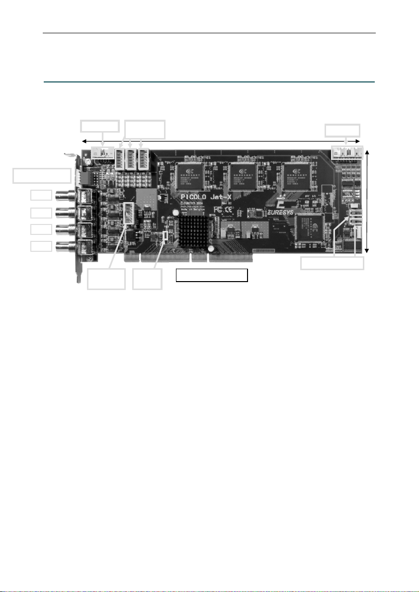
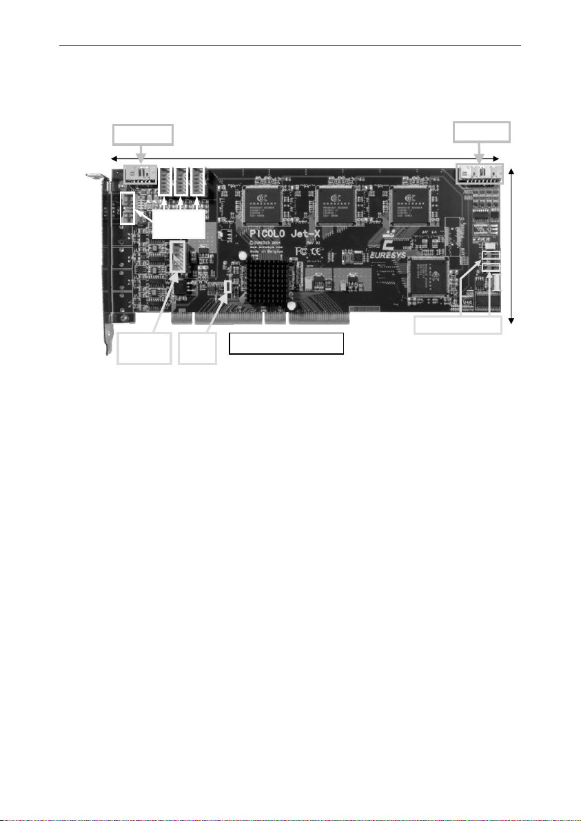
1. Product appearance
MIO LINK
75 ohms switches
VID1
VID2
VID3
VID4
VEB LINK
(video out)
Jet-X includes:
• 4 digitizers.
• 4 on-board JPEG encoders.
• A PCI-X bridge that doubles the throughput compared with Picolo Tetra. The usage of a PCI-X slot is
mandatory to achieve this performance.
• An optimized internal PCI bus between digitizers and PCI-X bridge.
Picolo Jet-X can be used in PCI-X 66 MHz, 100 MHz or 133 MHz slots. It also works in standard PCI slots, 32-bit or
64-bit, up to 66 MHz, 3.3 V or 5 V.
Starting with board revision B2_1, the PCI-X jumper is removed.
Expansion accessories are common with Picolo Tetra series. Video Expansion Bracket and Video Expansion
Bracket 12 are presented in part V. MIO module is described in part VI.
VEB LINK
video in)
1 2 3
PCI-X
jumper
265 mm / 10.43 in
PCI-X bus connector
Digital IO
PC reset headers
107 mm /
4.21 in
21

Picolo Jet-X Product Description
2. PCI requirements
PCI stands for "Peripheral Component Interconnect" and refers to standardized means to install an add-on board
inside a computer.
Picolo Jet-X is a medium-size PCI card to be inserted in a PCI-X slot inside a PC. The PCI edge connector is
compliant with the official PCI specification, revision 2.3 and PCI-X addendum revision 1.0. It is 64-bit wide, operates
at 133 MHz maximum, and supports 3.3 V or 5 V signaling systems.
Picolo Jet-X can be used in a 66 MHz, 100 MHz or 133 MHz PCI-X slot.
Picolo Jet-X can be used in a 33 MHz or 66 MHz PCI slot and using the PCI slot with 32-bit or 64-bit.
For more information, see “PCI Bus Variation” application note.
Picolo Jet-X uses the +3.3V, +5 V, +12 V and -12 V power supply rails provided by the PCI bus. The +12 V supply is
only provided to outside devices through the MIO LINK connector. The power consumption on this rail is therefore
system dependent and is protected by a 0.5 A circuit breaker with automatic reset.
Typical electrical consumption is as follows:
PCI power rail Current Power
Total power consumption is typically 13 W.
Notes:
1. Video Expansion Bracket and Video Expansion Bracket 12 do not consume any power.
2. These PCI characteristics do also apply to Picolo Jet-X-RC.
Video capture board internal consumption
+3.3 V 2 A 6.6 W
+5 V 1 A 5 W
-12 V 5 mA 0.06 W
Alimentation of outside devices
+ 12V Max. 0.5 A Max. 6 W
22

Picolo Jet-X Product Description
3. Connectors
3.1. “VIDn” connector
3.2. “VEB LINK” connectors
VID1
VID2
VID3
VID4
Presence
Notes:
1. Each video differential pair is composed of VIDn and GNDn, both connected to digitizer n
where n = 1, 2, 3 or 4.
2. To inform the system of the Video Expansion Bracket’s existence, simply short-circuit pin 9
“Presence” with pin 10 “Dig. GND”, digital ground of the Picolo Jet-X.
GND1
GND2
GND3
GND4
Dig. GND
VID1, VID2, VID3 and VID4 are
selectable color or monochrome
composite inputs. They are
terminated with removable 75 ohms
loads.
To modify the 75 ohms termination
setting, see “75 ohms switches”.
Each 10-pin header connector allows to connect
one Video Expansion Bracket with a Picolo
Tetra-X.
Three VEB LINK connectors are used to add
video inputs to a Picolo Jet-X. For more details,
see “Video input routing” in part V.
One VEB LINK connector is used for video
outputs of digitalized images. For more details,
see “Video output routing” in part V.
75 ohms
switches
1 2 3 4
VID1
VID2
VID3
VID4
3.3. “Digital IO” connector
Reserved
IO1
IO3
IO5
IO7
IO9
IO11
IO13
GND
IO2
IO4
IO6
IO8
IO10
IO12
GND
The “Digital IO” internal connector on the
Picolo Jet-X has 13 TTL I/O lines that can be
used by the MultiCam software driver as
inputs, outputs or trigger lines.
Other Euresys video capture boards use the
same connector.
3.4. “MIO LINK” connector
Using flat cables, this 10-pin header connector allows to interconnect a Picolo Jet-X to MIO modules.
For more details, see “MIO hardware installation” in part VII.
23

Picolo Jet-X Product Description
4. Features
4.1. PC reset headers
64-bit board
Picolo
Jet-X
PCI slot
The two "PC reset headers" are equivalent.
See also topic "Using the watchdog" in the electronic documentation.
4.2. 75 ohms switches
1 2 3 4
OFF ON
The switch n controls the 75 ohms termination of the
corresponding VIDn input, where n = 1, 2, 3 or 4.
In the factory configuration, all video terminations are active.
Therefore, all switches are closed (ON position).
To remove the termination, set the switch to OFF position.
A reset cable can be connected directly to a
"PC reset header". The watchdog uses a static
switch with an ON resistance of about 35 ohms.
The polarity at the switch input doesn't matter.
In the drawing is illustrated the control of PC
reset by button or by the Picolo Jet-X. The
switch can also be used for other purposes
than resetting the computer: for example, it can
activate an alarm.
24

Picolo Jet-X Product Description
4.3. PCI-X jumper
Picolo Jet-X is compatible with all PCI and PCI-X slots. Initial production boards (up to rev. B2_0) include a PCI-X
jumper.
If present, the factory setting of this jumper is shorted.
Remove the PCI-X jumper if you intend to insert Picolo Jet-X in a conventional PCI slot.
PCI slot category PCI-X jumper
Conventional PCI
PCI-X
open
shorted
PCI-X
jumper
25

V
V
Picolo Jet-X Product Description
5. Picolo Jet-X block diagram
Digital IO
VID 1
VID 2
VID 3
VID 4
Connectors on bracket
Electromagnetic compatibility network
EB LINK
(video in)
1
2
3
PIO
Video
MIO LINK
PC reset
headers
PCI control
Parallel
interface
Digitizer 1
With color
decoding
and scaling
Digitizer 2
With color
decoding
Common-mode noise removal
Quadruple 4-to-1 analog router
and scaling
Digitizer 3
With color
decoding
and scaling
Digitizer 4
With color
decoding
and scaling
Color
format
conversion
JPEG
Encoder
Color
format
conversion
JPEG
Encoder
Color
format
conversion
JPEG
Encoder
Color
format
conversion
JPEG
Encoder
PCI
Interface
PCI
Interface
PCI
Interface
PCI
Interface
PCI
Interface
PCI
Interface
PCI
Interface
PCI
Interface
Embedded PCI bus
Transparent
PCI-X bridge
Picolo Jet-X Block Diagram
EB LINK
(video out)
PCI-X connector
64 bits, 133 MHz
Video input/output routing
The detailed routing is presented in part V, “VEB and VEB12 Product Description”.
26

Picolo Jet-X Product Description
6. Picolo Jet-X and Jet-X-RC standard compliance
This equipment has been tested and found to comply with the limits for a Class B digital device, pursuant to Part 15 of
the FCC Rules.
These limits are designed to provide reasonable protection against harmful interference in a residential installation or
when the equipment is operated in a commercial environment.
This equipment generates, uses and can radiate radio frequency energy and, if not installed and used in accordance
with the instructions, may cause harmful interference to radio communications. However, there is no guarantee that
interference will not occur in a particular installation.
If this equipment does cause harmful interference to radio or television reception, which can be determined by turning
the equipment off and on, the user is encouraged to try to correct the interference by one or more of the following
measures:
• Reorient or relocate the receiving antenna.
• Increase the separation between the equipment and receiver.
• Connect the equipment into an outlet on a circuit different from that to which the receiver is connected.
• Consult the dealer or an experienced radio/TV technician for help.
This equipment has been tested and found to comply with EN55022/CISPR22 and EN55024/CISPR24. To meet EC
requirements, shielded cables must be used to connect a peripheral to the card. This product has been tested in a
typical class B compliant host system. It is assumed that this product will also achieve compliance in any class B
compliant unit.
Notice for USA
Compliance Information Statement (Declaration of Conformity Procedure) DoC
FCC Part 15
Notice for Europe
This product is in conformity with the Council Directive 89/336/EEC amended by
92/31/EEC and 93/68/EEC
27

This page is intentionally left blank.

Picolo RC Product Description
Part IV. Picolo RC Product Description
1. Common characteristics of RC boards
The suffix RC stands for “Remote Connection”.
Picolo RC series provide a solution to customize all the 16 video inputs.
Picolo RC series cover following models: Tetra-RC; Tetra-X-RC and Jet-X-RC.
Picolo RC series have all characteristics in common with the standard Picolo except:
• Removed BNC video inputs and 75 ohms switches.
• 4 internal connections for 4 video inputs VIDn.
• A completely blank bracket.
• Solder bridges BRn to activate video termination resistors of VIDn.
From the software point of view, an application developed with a Picolo will immediately work with the corresponding
Picolo RC.
Video Expansion Bracket, Video Expansion Bracket 12 and MIO module may also be connected to RC boards using
the same rules as standard Picolo boards.
29

Picolo RC Product Description
2. Product appearance of Tetra-RC
MIO LINK
VEB LINK
(video in)
1 2 3
168 mm / 6.61 in
PC reset headers
Digital IO
VID1
VID2
VID3
VID4
VEB LINK
(video out)
Wide PCI bus connector
107 mm /
4.21 in
30

Picolo RC Product Description
3. Product appearance of Tetra-X-RC
MIO LINK
168 mm / 6.61 in
1 2 3
PC reset headers
Digital IO
VEB LINK
(video in)
0
VEB LINK
(video out)
PCI-X
jumper
Note:
Starting with board revision A1_1, the PCI-X jumper is removed.
PCI-X bus connector
107 mm /
4.21 in
31
Picolo RC Product Description
4. Product appearance of Jet-X-RC
MIO LINK
0
2 3
1
VEB LINK
(video in)
265 mm / 10.43 in
Digital IO
107 mm /
4.21 in
VEB LINK
(video out)
PCI-X
jumper
PCI-X bus connector
Note:
Starting with board revision B2_1, the PCI-X jumper is removed.
PC reset headers
32

Picolo RC Product Description
5. PCI requirements
PCI characteristics of RC series are identical to corresponding standard boards.
For a complete description, please refer to Tetra, Tetra-X or Jet-X characteristics.
6. Connectors
6.1. “VIDn” 2-pin header connectors of Tetra-RC
VID1, VID2, VID3 and VID4 are selectable color or monochrome
composite inputs.
Each one is connected through a 2-pin header connector as illustrated.
6.2. “VEB LINK 0” connector of Tetra-X-RC and
Jet-X-RC
VID1
VID2
VID3
VID4
Presence
Note:
Each video differential pair is composed of VIDn and GNDn, both connected to
digitizer n, where n = 1, 2, 3 or 4.
GND1
GND2
GND3
GND4
Dig. GND
6.3. Other connectors
All other connectors of RC series are identical to corresponding standard board.
Concerned connectors are named : VEB LINK; DIGITAL IO; MIO LINK and PC Reset headers.
For a complete description, please refer to Tetra, Tetra-X or Jet-X characteristics.
This 10-pin header connector allows to
connect the first Video Expansion Bracket
with a Picolo RC.
On the “VEB LINK 0” connector, the
“Presence” pin is already shorted to digital
ground.
VID1
GND1
VID2
GND2
VID3
GND3
VID4
GND4
33

Picolo RC Product Description
7. 75 ohms solder bridges
VIDn video inputs (n = 1, 2, 3 or 4) have an on-board video termination resistor. The solder bridge BRn controls the
75 ohms termination of the corresponding VIDn input.
To activate a termination resistor, establish a solder connection at the desired BRn.
At delivery, no connection is present.
34

V
V
8. Block diagrams
8.1. Picolo Tetra-RC
Digital IO
PIO
Parallel
Interface
Picolo RC Product Description
MIO LINK
Connector
PCI Control
PC reset
headers
VID 1
GND 1
VID 2
GND 2
VID 3
GND 3
VID 4
GND 4
Electromagnetic Compatibility Network
EB LINK
(video in)
1
2
3
Picolo Tetra-RC Block Diagram
Digitizer 1
With color decoding,
scaling,
format conversion
Video
Common-Mode Noise Removal
Digitizer 2
With color decoding,
scaling,
format conversion
Digitizer 3
With color decoding,
scaling,
format conversion
FIFO Buffer 1
630 bytes
FIFO Buffer 2
630 bytes
FIFO Buffer 3
630 bytes
PCI
PCI
PCI
Interface
Interface
Embedded PCI bus
Interface
Quadruple 4-to-1 Analog Router
Digitizer 4
EB LINK
(video out)
With color decoding,
scaling,
format conversion
PCI Connector
64 bits, 66 MHz
FIFO Buffer 4
630 bytes
PCI
Interface
Transparent
PCI Bridge
35

V
V
V
8.2. Picolo Tetra-X-RC
Digital IO
PIO
network
Parallel
Electromagnetic
EB LINK
(video in)
0
EB LINK
(video in)
1
2
3
compatibility
interface
Quadruple 4-to-1 analog router
Picolo RC Product Description
MIO LINK
PCI control
Digitizer 1
with color decoding,
scaling,
format conversion
Digitizer 2
with color decoding,
scaling,
format conversion
Digitizer 3
with color decoding,
scaling,
format conversion
Digitizer 4
with color decoding,
scaling,
format conversion
PC reset
headers
FIFO buffer1
FIFO buffer 2
FIFO buffer 3
FIFO buffer 4
630 bytes
630 bytes
630 bytes
630 bytes
PCI
PCI
PCI
PCI
interface
interface
Embedded PCI bus
interface
interface
Transparent
PCI-X bridge
Picolo Tetra-X-RC Block Diagram
EB LINK
(video out)
PCI-X connector
64 bits, 133 MHz
36

V
V
V
8.3. Picolo Jet-X-RC
Digital IO
PIO
network
compatibility
Electromagnetic
Picolo RC Product Description
MIO LINK
PC reset
headers
PCI control
Parallel
interface
EB LINK
(video in)
0
EB LINK
(video in)
1
2
3
Quadruple 4-to-1 analog router
Picolo Jet-X-RC Block Diagram
EB LINK
(video out)
Digitizer 1
With color
decoding
and scaling
Digitizer 2
With color
decoding
and scaling
Digitizer 3
Digitizer 3
With color
decoding
and scaling
Digitizer 4
With color
decoding
and scaling
PCI-X connector
64 bits, 133 MHz
Color
format
conversion
JPEG
Encoder
Color
format
conversion
JPEG
Encoder
Color
format
conversion
JPEG
Encoder
Color
format
conversion
JPEG
Encoder
PCI
Interface
PCI
Interface
PCI
Interface
PCI
Interface
PCI
Interface
PCI
Interface
PCI
Interface
PCI
Interface
Transparent
PCI-X bridge
Embedded PCI bus
37

V
V
V
Picolo RC Product Description
9. Video input routing
9.1. Picolo Tetra-RC with customer patchpanel
Blank
Bracket
Picolo Tetra-RC
Digitizer 1
Digitizer 2
Digitizer 3
EB
LINK 1
Video
In 1
Video
In 2
Video
In 3
Video
In 4
Note:
If using Video Expansion Bracket, always connect the new Video Expansion Bracket in ascending order.
For more details, see “Input Video Expansion Bracket hardware installation” in part VII.
Video
In 5
Video
In 6
Video
In 7
Video
In 8
LINK 2
Video
In 9
Video
In 10
Video
In 11
Video
In 12
EB
LINK 3
Video
In 13
Video
In 14
Video
In 15
Video
In 16
EB
Customer
Patchpanel
Digitizer 4
38

V
V
V
V
Picolo RC Product Description
9.2. Picolo Tetra-X-RC or Jet-X-RC with customer patchpanel
Blank
Bracket
Tetra-X-RC or Jet-X-RC
EB
LINK 0
Digitizer 1
Digitizer 2
Digitizer 3
Digitizer 4
Video
In 1
Video
In 2
Video
In 3
Video
In 4
LINK 1
Video
In 5
Video
In 6
Video
In 7
Video
In 8
EB
LINK 2
Video
In 9
Video
In 10
Video
In 11
Video
In 12
EB
Video
In 13
Video
In 14
Video
In 15
Video
In 16
EB
LINK 3
Customer
Patchpanel
Note:
If using Video Expansion Bracket, always connect the new Video Expansion Bracket in ascending order.
For more details, see “Input Video Expansion Bracket hardware installation” in part VII.
39

This page is intentionally left blank.
VEB and VEB 12 Product Description
Part V. VEB and VEB 12 Product Description
1. Product appearance
1.1. Video Expansion Bracket – 4 additional video inputs / outputs
A Video Expansion Bracket (VEB) adds four video connections to a Picolo. They may be used as inputs or outputs,
depending of the selected VEB LINK connector (video in or video out).
75 ohms switches
VID1
VID2
VID3
VID4
37 mm / 1.46 in
107 mm /
4.21 in
VEB LINK
41

VEB and VEB 12 Product Description
1.2. Video Expansion Bracket 12 – 12 additional video inputs
A Video Expansion Bracket 12 (VEB12) adds twelve video inputs to a Picolo, using the three VEB LINK connectors
(video in).
VEB LINK
(video in)
75 ohms switches
VID1 to 12
45 mm / 1.77 in
107 mm /
4.21 in
42

2. Connectors
Video Expansion Bracket Video Expansion Bracket 12
VEB and VEB 12 Product Description
75 ohms
switches
1 2 3 4
VID1
VID2
VID3
VID4
2.1. “VIDn” connector
75 ohms
switches
VID1 to 12
On the Video Expansion Bracket, VIDn are metallic BNC
connectors.
VID1, VID2, VID3 and VID4 are selectable color or
monochrome composite inputs.
They are terminated with removable 75 ohms loads.
1
up to 12
43
VEB and VEB 12 Product Description
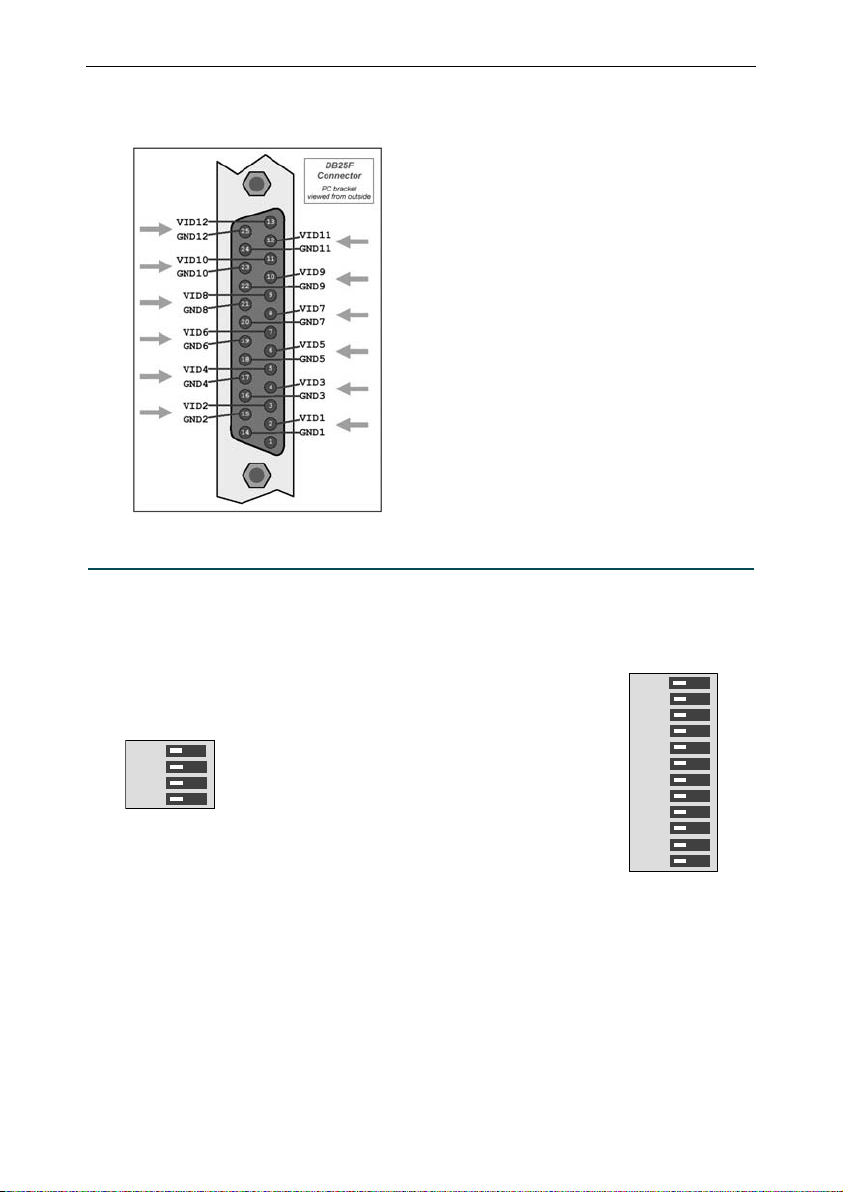
2.2. “VID1 to 12” connector
On the Video Expansion Bracket 12, the “VID1 to 12” connector
is composed of 12 video inputs and their respective ground. All
these video inputs are present on a standard DB25 female
connector.
VID1, VID2, … up to VID12 are color or monochrome
composite inputs. They are terminated with removable 75 ohms
termination resistors.
3. Features
3.1. 75 ohms switches
On the Video Expansion Bracket, four switches are present to
control the 75 ohms termination of the corresponding VIDn
input, where n = 1, 2, 3 or 4.
1 2 3 4
OFF ON
On the Video Expansion Bracket 12, twelve switches are
present to control the 75 ohms termination of the
corresponding VIDn input, where n = 1, 2,… or 12.
In the factory configuration, all video terminations are active.
Therefore, all switches are closed (ON position).
To remove the termination, set the switch to OFF position.
OFFON
1 2 3 4 5 6 7 8 9 10 11 12
44

VEB and VEB 12 Product Description
V
V
V
4. Video input/output routing
4.1. Video input routing with Video Expansion Brackets
Picolo board
Video
In 1
Video
In 2
Video
In 3
Video
In 4
On-board
Bracket
EB
LINK 1
EB
LINK 2
EB
LINK 3
Digitizer 1
Digitizer 2
Digitizer 3
Digitizer 4
Video
In 5
Video
In 6
Video
In 7
Video
In 8
Additional
Bracket 1
Video
In 9
Video
In 10
Video
In 11
Video
In 12
Additional
Bracket 2
Video
In 13
Video
In 14
Video
In 15
Video
In 16
Additional
Bracket 3
Note:
If using Video Expansion Bracket, always connect the new Video Expansion Bracket in ascending order.
For more details, see “Input Video Expansion Bracket hardware installation” in part VII.
45

VEB and VEB 12 Product Description
V
V
V
4.2. Video input routing with Video Expansion Bracket 12
The connection cable soldered on the Video Expansion Bracket 12 (VEB12) occupies the three VEB LINK connectors
(video in) of the Picolo Tetra series or the Picolo Jet-X.
Picolo board
Video
In 1
Video
In 2
Video
In 3
Video
In 4
On-board
Bracket
EB
LINK 1
Video
In 5
Video In 6
Video In 7
Video In 8
Video In 9
Video In 10
Video In 11
Video In 12
Video In 13
Video In 14
Video In 15
Video In 16
EB
LINK 2
EB
LINK 3
Digitizer 1
Digitizer 2
Digitizer 3
Digitizer 4
VEB 12
46

VEB and VEB 12 Product Description
V
4.3. Video output routing
As an alternative to looped-through connecting the video sources, Picolo Tetra series and Picolo Jet-X offer four
buffered video outputs. Available on the "VEB LINK (video out)" connector, the video outputs conveniently bring back
outside the video signals being digitized.
The user can implement a proprietary wiring system to use this connector. However, it is recommended to use a
Euresys' low-cost video expansion bracket as the most reliable way to maintain electromagnetic compatibility.
The optional video outputs are routed according to the following drawing.
Picolo board
Digitizer 1
Digitizer 2
Digitizer 3
Digitizer 4
EB LINK
(video out)
Video
Out 1
Video
Out 2
Video
Out 3
Video
Out 4
Additional
Bracket
47

VEB and VEB 12 Product Description
5. VEB and VEB 12 standard compliance
This equipment has been tested and found to comply with the limits for a Class B digital device, pursuant to Part 15 of
the FCC Rules.
These limits are designed to provide reasonable protection against harmful interference in a residential installation or
when the equipment is operated in a commercial environment.
This equipment generates, uses and can radiate radio frequency energy and, if not installed and used in accordance
with the instructions, may cause harmful interference to radio communications. However, there is no guarantee that
interference will not occur in a particular installation.
If this equipment does cause harmful interference to radio or television reception, which can be determined by turning
the equipment off and on, the user is encouraged to try to correct the interference by one or more of the following
measures:
• Reorient or relocate the receiving antenna.
• Increase the separation between the equipment and receiver.
• Connect the equipment into an outlet on a circuit different from that to which the receiver is connected.
• Consult the dealer or an experienced radio/TV technician for help.
This equipment has been tested and found to comply with EN55022/CISPR22 and EN55024/CISPR24. To meet EC
requirements, shielded cables must be used to connect a peripheral to the card. This product has been tested in a
typical class B compliant host system. It is assumed that this product will also achieve compliance in any class B
compliant unit.
Notice for USA
Compliance Information Statement (Declaration of Conformity Procedure) DoC
FCC Part 15
Notice for Europe
This product is in conformity with the Council Directive 89/336/EEC amended by
92/31/EEC and 93/68/EEC
48

MIO Module Product Description
Part VI. MIO Module Product Description
1. Product appearance
MIO stands for Module Input Output. This I/O module holds four isolated inputs and four isolated outputs.
It can be attached to a Picolo Pro 3 or a Picolo Tetra as described in “Connecting MIO”.
The MIO does not require a connection to the motherboard. However, when installed, it will occupy the space of a PCI
slot location.
MIO LINK
58 mm / 2.28 in
LEDs
SEL2
SEL1
SEL0
I/O screw terminal
49
MODE
jumper
107 mm /
4.21 in

MIO Module Product Description
A
2. Connectors
2.1. “I/O screw terminal” connector
The sixteen terminals constituting the eight I/O lines of the MIO are collected in a removable 16-position screw
terminal provided with each MIO.
Input 1
Input 2
Input 3
Input 4
Output 1
Output 2
Output 3
Output 4
Alarm /
Watchdog
Note:
The output 4 can be associated with a timer in order to be used as an alarm or a watchdog.
I1
I1G
I2
I2G
I3
I3G
I4
I4G
O1
O1B
O2A
O2B
O3A
O3B
O4A
O4B
2.2. “MIO LINK” connectors
Using flat cables, these 10-pin header connectors allow to link MIO with a Picolo Tetra, a Picolo Pro 3 or another MIO.
For more details, see “Connecting MIO”.
50

3. Features
3.1. LEDs
MIO Module Product Description
OUT1
OUT2
OUT3
OUT4
The input state is displayed with 4 green LEDs : the “INn” LED is lighted when the corresponding two terminals In and
InG are connected, where n = 1, 2, 3 or 4. For more details, see “Input thresholds”.
The output state is displayed with 4 orange LEDs : the “OUTn” LED is lighted when the corresponding terminal OnA is
connected to OnB (contact shorted).
IN1
IN2
IN3
IN4
51

MIO Module Product Description
4. MIO standard compliance
This equipment has been tested and found to comply with the limits for a Class B digital device, pursuant to Part 15 of
the FCC Rules.
These limits are designed to provide reasonable protection against harmful interference in a residential installation or
when the equipment is operated in a commercial environment.
This equipment generates, uses and can radiate radio frequency energy and, if not installed and used in accordance
with the instructions, may cause harmful interference to radio communications. However, there is no guarantee that
interference will not occur in a particular installation.
If this equipment does cause harmful interference to radio or television reception, which can be determined by turning
the equipment off and on, the user is encouraged to try to correct the interference by one or more of the following
measures:
• Reorient or relocate the receiving antenna.
• Increase the separation between the equipment and receiver.
• Connect the equipment into an outlet on a circuit different from that to which the receiver is connected.
• Consult the dealer or an experienced radio/TV technician for help.
This equipment has been tested and found to comply with EN55022/CISPR22 and EN55024/CISPR24. To meet EC
requirements, shielded cables must be used to connect a peripheral to the card. This product has been tested in a
typical class B compliant host system. It is assumed that this product will also achieve compliance in any class B
compliant unit.
Notice for USA
Compliance Information Statement (Declaration of Conformity Procedure) DoC
FCC Part 15
Notice for Europe
This product is in conformity with the Council Directive 89/336/EEC amended by
92/31/EEC and 93/68/EEC
52

Hardware Installation Procedure
Part VII. Hardware Installation Procedure
1. Warnings
Warning:
Electrostatic sensitive device
Picolo cards may be damaged by electrostatic discharges. Follow the procedure hereby described and apply any
general procedure aimed at reducing the risk associated with electrostatic discharge.
Any damage caused by improper handling is not covered by the manufacturer's warranty.
Warning:
Electromagnetic compatibility
Picolo cards are compliant with electromagnetic compatibility regulatory requirements.
To ensure this compliance, it is mandatory to secure the card bracket with the relevant screw according to the
procedure hereby described.
Failing to do so may affect image quality in allowing unwanted ground noise pickup.
Warning:
Risk of electrical shock
Do not operate the computer with any enclosure cover removed.
During the hardware installation, ensure the AC power cord is unplugged before touching any internal part of the
computer.
Warning:
Heating device
In operation, it is normal that Picolo cards dissipate some heat.
To ensure the adequate cooling effect of the fan equipping your computer, it is mandatory to correctly fit all enclosure
covers, including blank brackets.
53

Hardware Installation Procedure
2. Hardware installation procedure
Picolo board should be physically inserted in an available PCI slot of your computer before operation becomes
possible.
More than one Euresys board can be hosted by a common PCI bus, as long as slots are available.
Following the hardware installing procedure below is recommended:
Switch-off the computer and all peripheral devices connected to it (monitor, printer...).
Discharge any electricity that could be accumulated on your body. You can achieve this in touching with bare hand
an unpainted metal part of the enclosure of your computer. Make sure that the computer is linked to the AC mains
outlet with proper earth connection.
Disconnect all cables from your computer, including AC power.
Open the computer enclosure to gain access to the PCI slots according to the manufacturer’s instructions.
Ensure that the motherboard is fully compatible with the official PCI specification of the EureCard.
Locate an available PCI slot and remove the blank bracket associated with this location. To achieve this, remove
the securing screw and keep it aside for later use in the procedure. Keep the blank bracket in a known place for
possible re-use.
Unwrap the EureCard, take the board and carefully hold it. Avoid any contact of the board with unnecessary items,
including your clothes.
Gently insert the board in the targeted PCI slot, taking care to push it down fully into the slot. If you experience
some resistance, remove the board and repeat the operation. You should attempt to make a perfect mechanical
alignment of board relative to slot for best results. Ensure that the lower part of the bracket is inserting into the
corresponding enclosure fastening.
Secure the board with the saved screw.
Install the Video Expansion Brackets and MIO, if any.
Close the computer enclosure according to the manufacturer’s instructions.
54
Hardware Installation Procedure
V
V
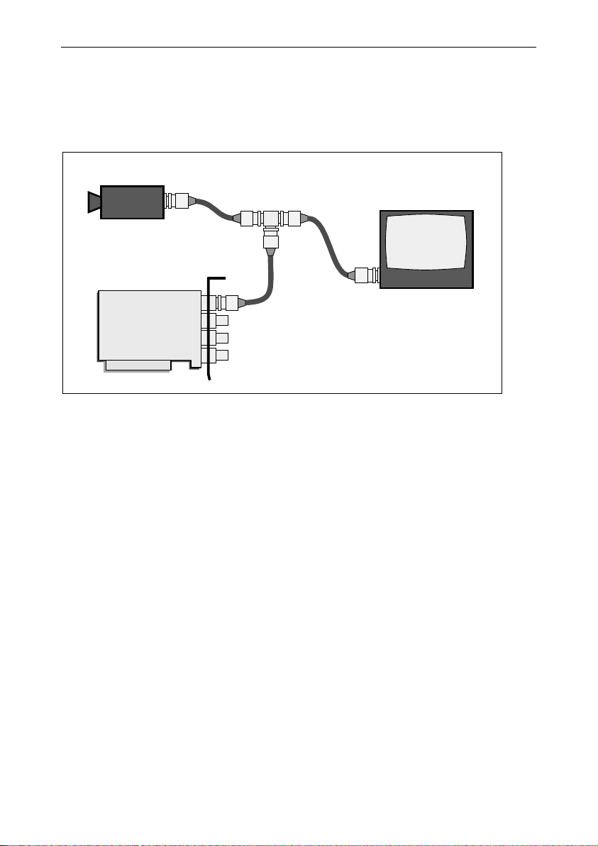
2.1. Usage of video terminations
The application may require the video signal to be monitored while being digitized by the capture board.
A possible way to address this requirement is using the looped-through technique. The coaxial cable delivering the
video signal from the source camera to the capture board is continued towards a video monitor. In that manner, the
camera serves both the board and the monitor.
This technique can be extended to distribute a video image to several video recipients. Each device where the video
cable is connected in and out to the next one is called a "loop-through connection".
In a Picolo-based system, any video input can be used in a loop-through fashion using an interconnecting "Tee"
structure.
There is one mandatory precaution to consider when using this technique.
Normally, any video recipient device terminates the coaxial line with a so-called termination resistor (valued 75 ohms
in video technology).
When using the looped-through technique, the termination resistor of all intermediate devices should be removed.
Only the terminal device keeps the termination.
In order to support the looped-through technique, the Picolo Tetra series, Jet-X and the additional Video Expansion
Brackets offer a way to remove the termination for any selected input.
A looped-through connection is available on the Picolo Tetra series and Jet-X using the VEB LINK (video out), see
“Video output routing”.
ideo
source
ideo
camera
Picolo board
Tee BNC
adaptor
Looped-through
video recipient
Terminal
video recipient
Video monitor
55

Hardware Installation Procedure
3. Picolo RC series hardware installation
3.1. 75 ohms solder bridges
On Picolo Tetra-RC, Picolo Tetra-X-RC and Picolo Jet-X-RC, the VIDn video inputs (n = 1, 2, 3 or 4) have an on-board
video termination resistor. The solder bridge BRn controls the 75 ohms termination of the corresponding VIDn input.
Solder bridges are at the back of Picolo board, see picture.
To activate a termination resistor, establish a solder connection at the desired BRn (n = 1, 2, 3 or 4).
At delivery, no connection is present.
56

Hardware Installation Procedure
4. Input Video Expansion Bracket hardware installation
4.1. Connection
When using Video Expansion Brackets, it is mandatory to link them using the following connectors of Picolo series:
Configuration Connect to
Picolo and 1 Video Expansion Bracket VEB LINK 1
Picolo and 2 Video Expansion Brackets VEB LINK 1 and 2
Picolo and 3 Video Expansion Brackets VEB LINK 1, 2 and 3
Note:
Before installing or removing any Video Expansion Bracket, power down the PC.
4.2. 75 ohms switches
1
2
3 4
OFFON
The dip switch n controls the 75 ohms termination of the corresponding VIDn input (n = 1, 2, 3 or 4).
In the default configuration, all video inputs are 75 ohms terminated. Therefore, all switches are closed (ON position).
To remove the the 75 ohms termination, set the switch to OFF position.
5. Output Video Expansion Bracket hardware installation
5.1. 75 ohms switches
1 2 3 4
OFFON
The switch n controls the 75 ohms termination of the corresponding VIDn output (n = 1, 2, 3 or 4).
In the default configuration, all video outputs are 75 ohms terminated. Therefore, all switches are closed (ON position).
On each video output, the 75 ohms termination should be removed. Therefore, set all switches to OFF position.
57

Hardware Installation Procedure
6. MIO hardware installation
6.1. Identification
All modules MIO linked with a Picolo Tetra series must have a unique identification (ID). Failing to do so will cause
logic signal contention. Set the MIO identification when the system is shut off.
MIO ID SEL2 SEL1 SEL0
0
1
2
3
4
means a jumper shorted.
means a jumper open.
MODE
jumper
SEL2
SEL1
6.2. Mode jumper
This jumper is used to select either the alarm or watchdog functionality.
Function MODE jumper
Alarm
Watchdog
The factory setting of the MODE jumper is open.
open
shorted
58

Hardware Installation Procedure
6.3. Connecting MIO
Up to 5 MIO modules can be connected to the same Picolo Tetra series.
MIO are daisy-chained with flat cables at their MIO LINK connectors; one of them must be linked to the MIO LINK
connector of a Picolo Tetra series.
All cables are identical and may be interchanged.
MIO does not need a PCI slot, any blind slot is adequate.
59

This page is intentionally left blank.

MultiCam Installation Guide
Part VIII. MultiCam Installation Guide
1. Hardware requirements
Following features are recommended to operate MultiCam :
CPU Pentium III Class or above
System memory Minimum 128 MB
Hard disk drive Minimum 150 MB free
2. Linux installation
2.1. Run-time software requirements
MultiCam and EureCards can be operated on the following Linux operating systems.
OS version Additional information
RedHat 7.3 Kernel 2.4.18-3
RedHat 8.0 Kernel 2.4.18-14
Refer to the release notes for updated information about OS and supported boards.
2.2. Development software requirements
MultiCam comes with documentation, development tools and sample programs.
The documentation is provided in standard CHM format. It is better viewed using xchm.
In addition, some information may be provided as Adobe Acrobat PDF files. To view these files it is required to use an
appropriate PDF file viewer. For example: xpdf or Adobe Acrobat Reader 4 (or later).
The development tools are C or C++ based. Thus all popular development environments can be used to develop
applications using EureCards and MultiCam.
Sample programs are provided for various development environments.
2.3. Installation instructions
Switch on your computer and start Linux.
Place Euresys CD-ROM in the drive and mount it.
Copy multicam-n.n.tar.gz on hard disk drive where n.n is the release number
of MultiCam.
For example, using release 4.5 of MultiCam, copy multicam-4.5.tar.gz.
Extract this archive: # tar -xzvf multicam-n.n.tar.gz
Go in directory multicam: # cd multicam-n.n
Log in as root.
Execute the installation script: # ./install
Check for proper installation: connect a camera to the Picolo board and run
eVisionStudio.
61

MultiCam Installation Guide
3. Windows installation
3.1. Run-time software requirements
MultiCam and EureCards can be operated with the following Microsoft Windows operating systems.
OS version Additional information
Windows server 2003 -
Windows XP Embedded -
Windows XP -
Windows 2000 Service Pack 2 or later
Refer to the MultiCam Installation Guide for updated information about OS versions.
3.2. Development software requirements
MultiCam comes with documentation, development tools and sample programs.
The documentation is provided in Microsoft standard CHM format. To view the documentation, Internet Explorer 4 or
later must be installed on your system. For your convenience, a version of Internet Explorer is provided on most
Euresys CD-ROM.
In addition, some information may be provided as Adobe Acrobat PDF files. To view these files it is required to use
Adobe Acrobat Reader 4 or later. For your convenience, a version of Adobe Acrobat Reader is provided on most
Euresys CD-ROMs.
The development tools are C, C++, and ActiveX based. Thus all popular development environments can be used to
develop applications using EureCards and MultiCam.
Sample programs are provided for various development environments. Refer to the release notes for detailed
information about the supported development environment versions.
3.3. Installation instructions
Switch on your computer and start Windows. Log in with administrative rights.
If a EureCard was newly added in the system, Windows "Hardware installation Wizard" will detect the EureCard and
possibly prompt for user action. If this prompt appears, click on the "Cancel" button.
Place Euresys CD-ROM in the drive. The setup application starts automatically. If the setup doesn't start, you may run
'setup.exe' directly from the CD-ROM.
Select the option to install MultiCam.
Depending on the operating system, the installation procedure may differ. Follow carefully the setup program
instructions.
After the installation process, execute the EasyGrab application to control the proper system operation.
62

Technical Specifications
Part IX. Technical Specifications
1. Technical specifications for all Picolo products
1.1. Video image formats
The Picolo Tetra video capture boards acquire color or monochrome video images from composite interlaced video
signals. The NTSC and PAL color standards are supported. The monochrome video acquisition complies with the socalled CCIR (625 lines) and EIA RS-170 (525 lines) standards.
Acquisition of full frame (two fields) or single field images is selectable.
1.2. Acquisition
Before PCI transfer to the PC, the acquired images can be scaled to any format smaller than the original one, down to
1/12. The downscaling process involves a sophisticated hardware device, performing an accurate interpolation in both
the horizontal and vertical direction. The image buffer for a downscaled image is smaller in size, and its transfer needs
less PCI bandwidth.
Moreover, any part of the incoming image can be retained for further PCI transfer, allowing to define region of interest.
All desirable adjustments can be applied to the images during acquisition, such as video contrast, brightness, color
saturation and hue (NTSC only).
1.3. Synchronization
A fully digital technique is used to synchronize the digitizer operation on the incoming video signal. This ensures a
stable and robust operation despite the varying video conditions.
A poor video signals issued by a low end VCR is robustly supported. When using high-quality video surveillance
cameras, the acquisition performance is exemplary, as demonstrated by a jitter figure in the nanosecond range.
1.4. Image fidelity
All precautions have been taken in the Picolo Tetra to ensure an excellent fidelity of the grabbed bitmap in respect of
the original video signal. In particular, environmental conditions may induce common-mode noise in the signal issued
by distant cameras. Picolo Tetra has special circuitry to remove this defect, and this is highly appreciated in the video
surveillance applications.
63

Technical Specifications
1.5. Bitmap image formats
Before storing the acquired images into the destination memory buffer, a pixel format conversion takes place in realtime. Numerous color or monochrome formats can be chosen.
Packed Planar
RGB32 YCrCb 4:2:2
RGB24 YCrCb 4:1:1
RGB16 YCrCb 4:2:0
RGB15 YCrCb 4:1:0
YCrCb 4:2:2 YCbCr 4:2:0
YCrCb 4:1:1 YCbCr 4:1:0
Y8
1.6. Bus mastering
All Picolo video capture boards are PCI bus mastering agents that directly store the acquired images into the PC
physical memory without CPU involvement. As a unique feature, Picolo automatically recovers the scatter-gather
virtual memory mapping to present the data as a regular bitmap image in a user allocated memory buffer.
64

Technical Specifications
2. Picolo Tetra series technical specifications
2.1. Characteristics
Parameter
Dimensions
Power consumption 8 W 9 W 0 W 0 W
PCI capability 64 bits, 66 MHz 64 bits, 66 MHz - -
PCI-X capability - 64 bits, 133 MHz - -
TTL I/O lines 13 I/O lines - -
Certification FCC class B, CE and EN50130-4
Video connections Up to 16 cameras with three Video Expansion Brackets
Note:
Number of I/O lines may be extended using up to 5 MIO.
Configuration Number of video inputs
Picolo Tetra only 4
Picolo Tetra and 1 Video Expansion Bracket 8
Picolo Tetra and 2 Video Expansion Brackets 12
Picolo Tetra and 3 Video Expansion Brackets 16
Picolo Tetra and 1 Video Expansion Bracket 12 16
Picolo Tetra,
Picolo Tetra-RC
or one Video Expansion Bracket 12
2.2. Recommended operating conditions
Parameter Symbol Min Typ Max Units Note
Power supply +5V V
Power supply +12V V
Power supply -12V V
Overall peak to peak
amplitude
Analog video
input levels
Ambient operating temperature TA 0 50 °C
Notes:
1. Vertical Sync pattern (equalisation pulses & serration pulses) must comply with PAL/NTSC standard.
2. SAR=SL
amplitude of the sync tip of video signal before switching.
3. Peak to peak amplitude of noise within the sync part of the video line measured with a low-pass filter of
20 MHz cut-off frequency.
Sync amplitude
Sync amplitude ratio SAR 0.3 3.3 2
Rise/fall time of sync edges 50 300 ns
Tolerated noise on sync 50 mV 3
Input voltage range VDM -2.0 2.0 V
/SLB where SLA is the amplitude of the sync tip of video signal after switching and SLB is the
A
Picolo Tetra-X,
Picolo Tetra-X-RC
168 mm x 107 mm 37 mm x 107 mm 45 mm x 107 mm
6.61 in x 4.21 in 1.46 in x 4.21 in 1.77 in x 4.21 in
+12V
-12V
Vin 0.6 1.0 2.0 V
Vsync
Video Expansion
Bracket
4.75 5.00 5.25 V
+5V
11 12 13 V
-11 -12 -13 V
180 300 600 mV
Video Expansion
Bracket 12
1
65

Technical Specifications
2.3. Power supply currents requirements
Parameter Symbol
Supply current for +5V I
Supply current for +12V I
Supply current for -12V I
1.30 1.50 A
+5V
+12V
5 5 mA
-12V
Max on Picolo Tetra,
Picolo Tetra-RC
120 120 mA
Max on Picolo Tetra-X,
Picolo Tetra-X-RC
Units
2.4. DC characteristics
Parameter Symbol Min Max Units
Digital inputs
(IO1..13)
Digital outputs
(IO1..13)
Analog video
inputs
Input high voltage VIH 3.5 5.0 V
Input low voltage VIL 0 1.5 V
Output high voltage
(I
= -30 to -300 µA)
OH
Output low voltage (IOL=1.6 mA) VOL 1.4 V
Output low level current IOL 0 10 mA
Common mode voltage range
(VDM=±1V)
VOH 3.5 5.0 V
VCM -2.0 2.0 V
2.5. Performance parameters
Parameter Min Typ Max Units Note
Horizontal lock range ± 7 % of line length
Color sub-carrier lock-in range ±800 Hz
Overall AGC range -6 +6 dB
AGC recovery delay after video source switch 1 Field_period 1
Low signal threshold 133 mV 2
Recovery delay after video
source switching
Video input CMRR @ 50 Hz 60 dB
Video input CMRR @ 4 MHz 40 dB
Notes:
1. With worst case sync amplitude ratio.
2. Sync amplitude threshold of "EC_ERROR_NOSIG" in MultiCam.
3. Acquisition begins immediately after this delay.
0.8<SAR<1.25 1 1.5 2 Field_period 3
0.5<SAR<2.0 1 1.5 4 Field_period 3
66

Technical Specifications
3. Picolo Jet-X technical specifications
3.1. Characteristics
Parameter Picolo Jet-X Video Expansion Bracket
Dimensions
Power consumption 13 W 0 W 0 W
PCI capability 64 bits, 66 MHz - -
PCI-X capability 64 bits, 133 MHz - -
TTL I/O lines 13 I/O lines - -
Certification FCC class B, CE and EN50130-4
Video connections
Note:
Number of I/O lines may be extended using up to 5 MIO.
Configuration Number of video inputs
Picolo Jet-X only 4
Picolo Jet-X and 1 Video Expansion Bracket 8
Picolo Jet-X and 2 Video Expansion Brackets 12
Picolo Jet-X and 3 Video Expansion Brackets 16
Picolo Jet-X and 1 Video Expansion Bracket 12 16
265 mm x 107 mm 37 mm x 107 mm 45 mm x 107 mm
10.43 in x 4.21 in 1.46 in x 4.21 in 1.77 in x 4.21 in
Up to 16 cameras with three Video Expansion Brackets
or one Video Expansion Bracket 12
3.2. Recommended operating conditions
Parameter Symbol Min Typ Max Units
Power supply +3.3V V
Power supply +5V V
Power supply +12V V
Power supply -12V V
Ambient operating temperature TA 0 50 °C
3.14 3.3 3.46 V
+3.3V
4.75 5.00 5.25 V
+5V
11 12 13 V
+12V
-11 -12 -13 V
-12V
Video Expansion
Bracket 12
67

Technical Specifications
3.3. Power supply currents requirements
Parameter Symbol Max Units
Supply current for +3.3V I
Supply current for +5V I
Supply current for +12V I
Supply current for -12V I
2 A
+3.3V
1 A
+5V
0.5 A
+12V
5 mA
-12V
Note:
The +12 V supply is only provided to outside devices through the MIO LINK connector.
3.4. DC characteristics
Parameter Symbol Min Max Units
Digital inputs
(IO1..13)
Digital outputs
(IO1..13)
Input high voltage VIH 3.5 5.0 V
Input low voltage VIL 0 1.5 V
Output high voltage
(I
= -30 to -300 µA)
OH
VOH 3.5 5.0 V
Output low voltage (IOL=1.6 mA) VOL 1.4 V
Output low level current IOL 0 10 mA
68

Technical Specifications
4. MIO technical specifications
4.1. Characteristics
Dimensions
Power consumption 1.8 W (150 mA @ +12 V)
Certification FCC class B and CE
I/O lines
4.2. Input thresholds
The four inputs are electrically isolated (by optocoupler) from the potential of the PC case in which the Picolo is
inserted. However they are not isolated from each other.
Each input is represented by two terminals named In and InG, where n = 1, 2, 3 or 4.
An input is active when In and InG are connected. In this condition, a DC current of about 3.5 mA flows between In
and InG.
An input is inactive when the terminals In and InG are disconnected.
58 mm x 107 mm
2.28 in x 4.21 in
4 opto-isolated inputs
and 4 reed relay outputs
MIO
Isolated
internal
voltage
+5 V
1 kΩ
LED
optocoupler
System
In
InG
Im
ImG
Input n
Input m
The input state is displayed with 4 green LEDs: a LED is lighted when the corresponding input is active.
VIn – V
Effect
InG
< -1 V Forbidden
-1 to 1.5 V Active input detected
1.5 to 10 V Inactive input detected
> 10 V Forbidden
69

Technical Specifications
A
4.3. Output characteristics
The four outputs are electromagnetic dry-contact reed relays. So electrical isolation from the PC case potential and
other outputs is provided.
Each output is represented by two terminals named OnA and OnB, where n is 1, 2, 3 or 4.
An output is active when OnA is connected to OnB (contact shorted). In these conditions, a current of 1A maximum
can flow, in any direction, through the contacts.
An output is inactive when OnA and OnB are not connected (contact opened). In these conditions, a voltage of 200 V
maximum can be sustained between the terminals.
The output state is displayed with 4 orange LEDs: a LED is lighted when the corresponding output is active.
The output 4 of the MIO module can be associated with a timer in order to be used as alarm or watchdog. At start up,
this association is done, unless AlarmConfig or WatchDogConfig is DISABLE. See electronic documentation.
Parameter Maximum value
Switched current 0.5 A
Switched voltage 200 V
Switched power 10 W
Note:
The product of the switched current and the switched voltage cannot be greater than the switched power.
MIO
Dry-contact
reed relay
On
Output n
OnB
70
 Loading...