

PC1656 Picolo.net HD4 Handbook
Firmware Version 5.x
©
EURESYS s.a. 2013 - Document version 1.0.288 built on 2013-02-15

2
PC1656 Picolo.net HD4 Handbook Disclaimer
EURESYS s.a. shall retain all property rights, title and interest of the documentation of the hardware and the software,
and of the trademarks of EURESYS s.a. All the names of companies and products mentioned in the documentation
may be the trademarks of their respective owners. The licensing, use, leasing, loaning, translation, reproduction,
copying or modification of the hardware or the software, brands or documentation of EURESYS s.a. contained in
this book, is not allowed without prior notice. EURESYS s.a. may modify the product specification or change the
information given in this documentation at any time, at its discretion, and without prior notice. EURESYS s.a. shall
not be liable for any loss of or damage to revenues, profits, goodwill, data, information systems or other special,
incidental, indirect, consequential or punitive damages of any kind arising in connection with the use of the hardware
or the software of EURESYS s.a. or resulting of omissions or errors in this documentation.

3
Contents PC1656 Picolo.net HD4 Handbook
Contents
Short Description.......................................................................................................................................... 6
Mechanical Specification........................................................................................................................ 8
Product Pictures....................................................................................................................................................... 8
Dimensions and Weight........................................................................................................................................... 9
Mounting Methods.................................................................................................................................................... 9
Desktop Mount....................................................................................................................................................10
Wall Mount.......................................................................................................................................................... 10
DIN-Rail Mount................................................................................................................................................... 14
Connectors, LED Indicators, and Switches........................................................................................................... 15
Location and Markings....................................................................................................................................... 15
Connectors.......................................................................................................................................................... 16
LED Indicators and Switches............................................................................................................................. 23
Electrical Specification.......................................................................................................................... 25
Power Input............................................................................................................................................................ 25
HD-SDI / HDcctv 1.0 Inputs...................................................................................................................................25
COM I/O................................................................................................................................................................. 26
Alarm Inputs........................................................................................................................................................... 27
Relay Outputs.........................................................................................................................................................28
Using Relay Outputs.............................................................................................................................................. 29
Audio Inputs............................................................................................................................................................31
Environmental Specification..............................................................................................................32
Operating Conditions..............................................................................................................................................32
Storage Conditions................................................................................................................................................. 32
Compliance............................................................................................................................................................. 33
Functional Specification....................................................................................................................... 34
Video Specifications............................................................................................................................................... 34
Video Source Specification.................................................................................................................................35

4
PC1656 Picolo.net HD4 Handbook Contents
Video Encoder Specification...............................................................................................................................37
Audio Specifications............................................................................................................................................... 39
Streaming Specifications........................................................................................................................................ 40
Media Transport Protocols..................................................................................................................................40
RTP Transport Modalities................................................................................................................................... 41
RTP Transport Media Types.............................................................................................................................. 41
Network Specifications........................................................................................................................................... 42
IP Address Allocation Methods.......................................................................................................................... 42
TLS Protocol....................................................................................................................................................... 43
System Integration Specifications.......................................................................................................................... 44
Temperature Monitor.............................................................................................................................................. 44
Auto Setup Profiles................................................................................................................................................ 45
Time and Date........................................................................................................................................................45
Access Control....................................................................................................................................................... 46
Software Specification........................................................................................................................... 48
Software Components............................................................................................................................................ 48
Client Interfaces......................................................................................................................................................50
Web Services......................................................................................................................................................... 51
ONVIF Device Service........................................................................................................................................51
Proprietary Device Service................................................................................................................................. 52
ONVIF Media Service.........................................................................................................................................52
Proprietary Media Service.................................................................................................................................. 53
ONVIF Event Service......................................................................................................................................... 53
ONVIF PTZ service............................................................................................................................................ 54
Proprietary PTZ service......................................................................................................................................55
ONVIF Device IO Service.................................................................................................................................. 56
Proprietary Device IO service............................................................................................................................ 57
Web Pages Description......................................................................................................................... 59
Home Page.............................................................................................................................................................59
Home Page - Anonymous user............................................................................................................................. 61
Media Profiles Page............................................................................................................................................... 63
Media Profile Page.................................................................................................................................................64
Configurations Page............................................................................................................................................... 67
Edit Video Encoder Configuration Page................................................................................................................ 73
Edit Audio Encoder Configuration Page................................................................................................................ 74
Edit Metadata Configuration Page.........................................................................................................................75
Digital Inputs & Relay Outputs Page.....................................................................................................................76
PTZ Page............................................................................................................................................................... 79
Device Management Page - Network Tab............................................................................................................. 81
Device Management Page - Time Tab.................................................................................................................. 83
Device Management Page - Discovery Tab.......................................................................................................... 85
Device Management Page - Maintenance Tab..................................................................................................... 86

5
Contents PC1656 Picolo.net HD4 Handbook
Users Management Page...................................................................................................................................... 87
Hidden Pages......................................................................................................................................................... 90
Check Status Page.............................................................................................................................................90
Open Source Licenses Page............................................................................................................................. 91
Video Status Page..............................................................................................................................................92
Product Maintenance...............................................................................................................................93
Firmware Upgrade..................................................................................................................................................93
Configuration Backup and Restore........................................................................................................................93
Appendix........................................................................................................................................................... 94
About ONVIF.......................................................................................................................................................... 94
Detailed Access Policy - Firmware version 5.0.....................................................................................................95
Optional ONVIF Capabilities - Firmware version 5.0...........................................................................................103
Open Source Software.........................................................................................................................................105
Precautions of Use...............................................................................................................................................105
Embedded Firmware Naming Conventions......................................................................................................... 106

6
PC1656 Picolo.net HD4 Handbook Short Description
Short Description
Picolo.net HD4 is a four-channel High Definition Video IP encoder.
Video Features
Picolo.net HD4 captures high-definition video from up to four HD-SDI or HDcctv 1.0 video sources. It supports 720p
and 1080p progressive-scan formats, and a large set of frame rates for both 50Hz and 60Hz regions.
The format selection is automatic.
Picolo.net HD4 is fitted with a high performance H.264 encoder engine that is capable of delivering up to 12 encoded
video streams simultaneously.
The H.264 encoder operates in the baseline, main, and high profiles. The bitrate is controlled using the CBR or the
VBR methods.
Picolo.net HD4 is also capable of delivering up to 4 MJPEG encoded video streams.
Audio Features
Picolo.net HD4 can optionally be fitted with one or two Audio Module for Picolo.net HD4.
Each module provides two analog audio input ports and two audio output ports through four 3.5mm TRS jack sockets
located on the front panel.
The audio inputs accept line-level mono-channel audio signals. The audio input signals are digitally sampled, G.711
µ-law encoded, and finally delivered as a 64 kbps digital audio stream.
Note. Firmware version 5.x support neither audio outputs nor microphone level audio inputs
IO Features
Picolo.net HD4 provides the following I/O interfaces:
4 alarm input ports
4 isolated relay output ports
1 bidirectional half-duplex RS-485 COM port for the control of up to 4 Pelco-D compliant PTZ cameras
Network Features
Picolo.net HD4 provides a gigabit capable RJ-45 Ethernet port for connection to an IP network.
Streaming Features
Picolo.net HD4 uses the Real-time Transport Protocol - RTP - to stream audio, video and metadata over the IP
network.
It supports the following RTP transport modalities:
RTP over UDP Unicast
RTP over UDP Multicast
RTP interleaved in RTSP over HTTP

7
Short Description PC1656 Picolo.net HD4 Handbook
The streaming is controlled by means of the RTSP protocol. Each RTSP session may include:
One encoded video stream from any of the Video Encoders
One encoded audio stream from any of the Audio Encoders
One metadata stream from any of the Event sources
User Authentication and Access Policy
Picolo.net HD4 implements the following user authentication mechanisms to control the access to its resources:
HTTP and RTSP authentication using the "HTTP Digest Authentication" mechanism
WS authentication using the WS-Security “Username Token” mechanism, with the “Password Digest” password
type.
Web Pages through login/password dialog box.
Picolo.net HD4 implements the default access policy recommended by the ONVIF 2.2 Core Specification. The policy
implements four user levels: Administrator, Operator, User, and Anonymous.
Encryption
Picolo.net HD4 implements the following encryption mechanisms:
Web Service messages encryption using TLS 1.0
HTTPS Web Pages encrypted access using TLS 1.0
Compliance
Picolo.net HD4 is an encoder device complying with the version 1.0 of the ONVIF Profile S Specification.
The HD-SDI video inputs of Picolo.net HD4 comply with the Version 1.0 of the HDcctv Alliance standard. The device
has been tested according to the Version 1.1 HDcctv Compliance Certification Standard and has been found to be
in compliance with the Minimum Requirements.
Physical
Picolo.net HD4:
Is packaged in an aluminum enclosure that can be installed on a desktop, on a wall using a baseplate, or on a
DIN-rail using a clip-on baseplate.
Is intended for indoor use exclusively.
Is a fan-less device that supports ambient temperatures up to 55°C or 131°F.
Is 12V-24V DC powered.
Note. Pre-series products, SN00011 up to SN00070, are restricted for use with 12V DC supply!
8
PC1656 Picolo.net HD4 Handbook Mechanical Specification
Mechanical Specification
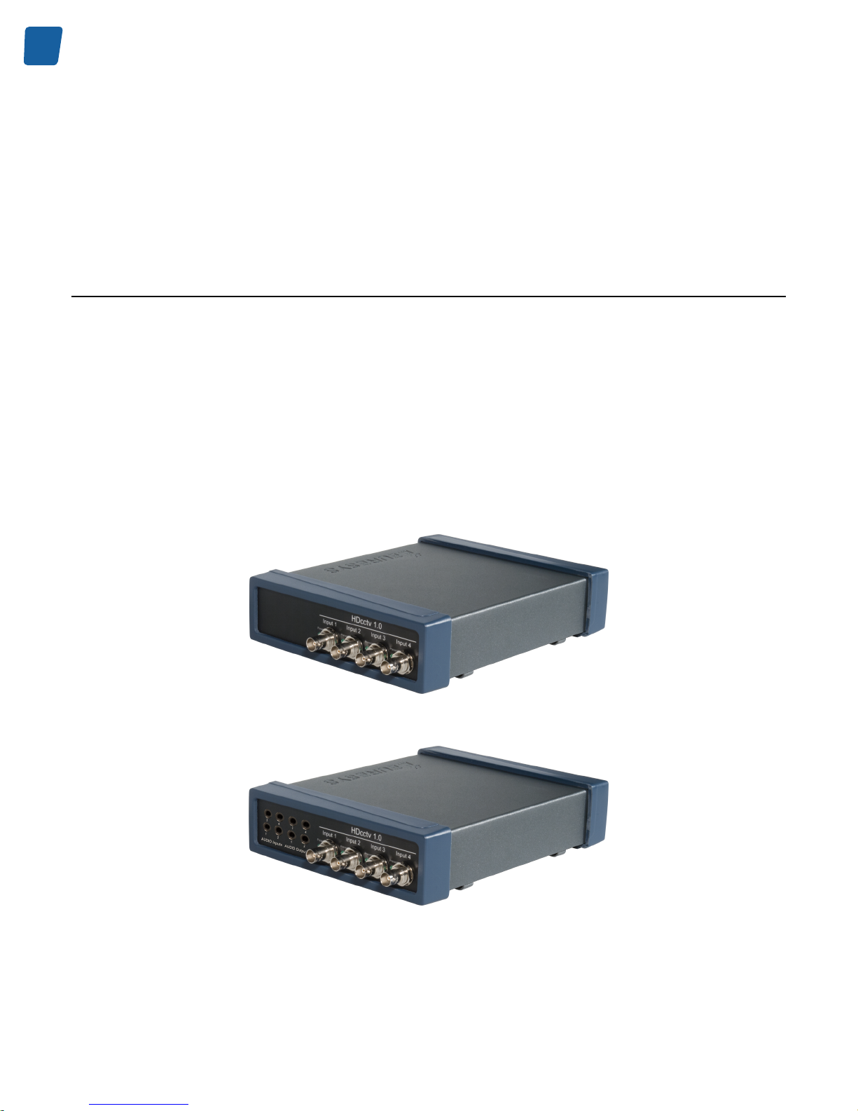
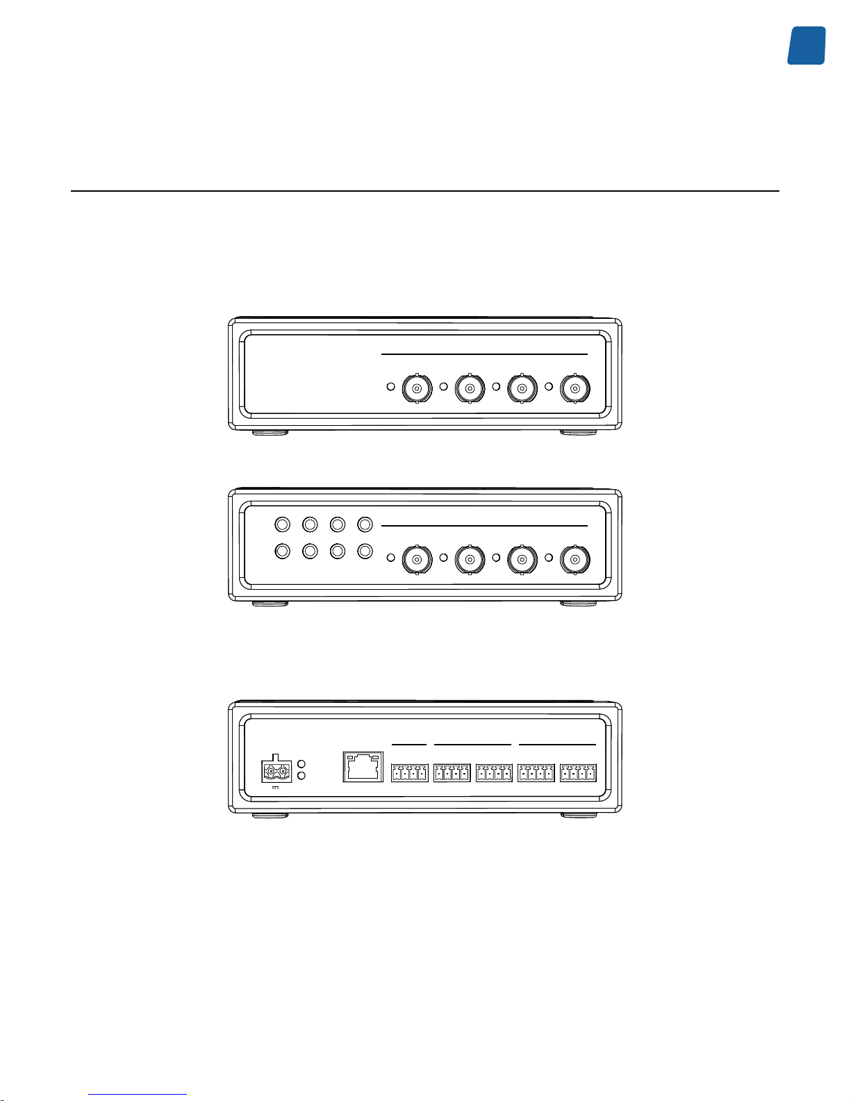
Product Pictures
The following figures show the Picolo.net HD4 ready to be installed on a Desktop.
The product is packaged into a grey-painted aluminum box terminated at both ends with two shock-protecting annular
plastic caps.
When Picolo.net HD4 is not fitted with audio modules, the front side holds the video connectors and the "Video
Present" green LED indicators.
When fitted with one or two Audio Module for Picolo.net HD4, the front side holds the audio connectors, the video
connectors, and the "Video Present" green LED indicators.
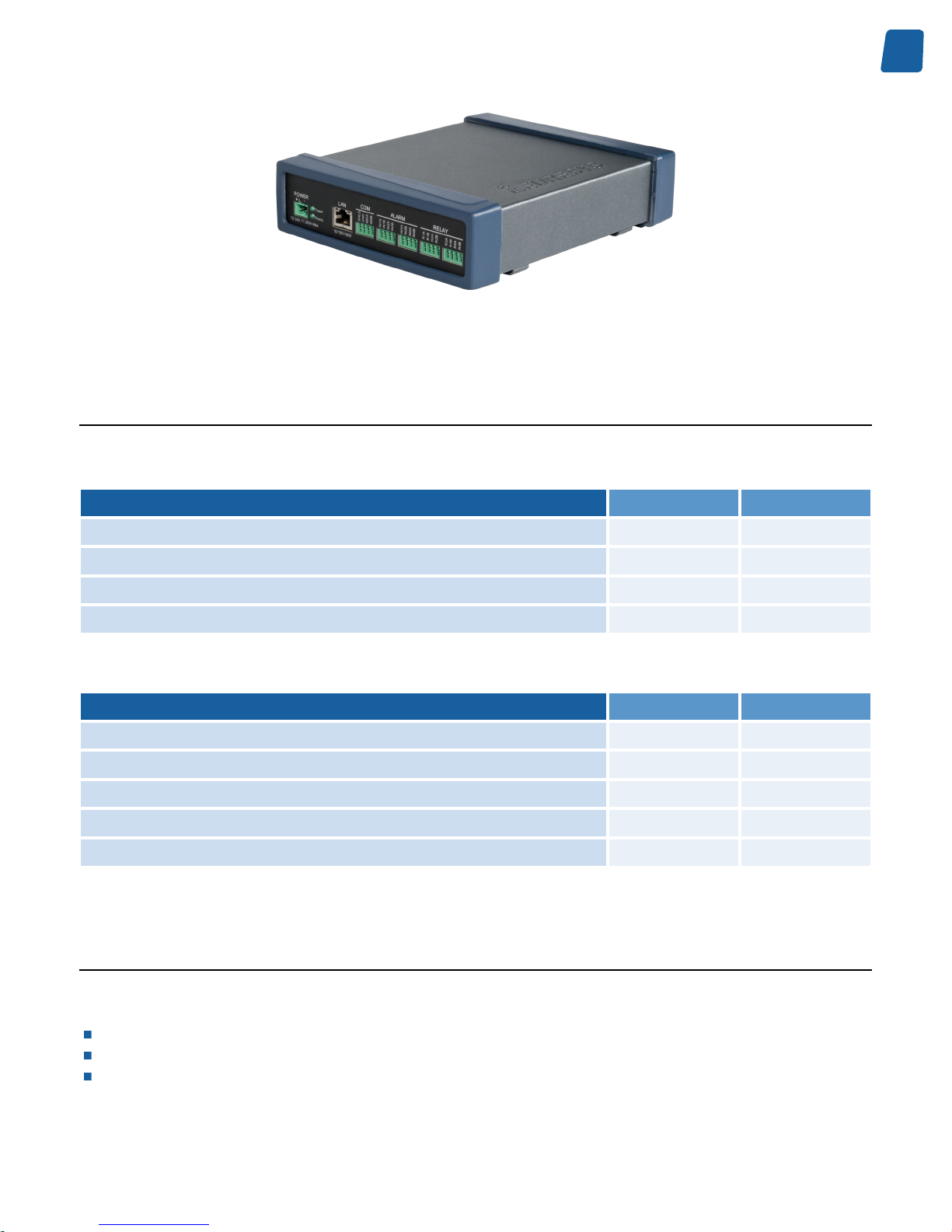
The top side is embossed with the Euresys logo.
The rear side holds the power input, I/O, and LAN connectors together with the Power OK and LAN status LED
indicators
Picolo.net HD4 without audio module(s) - Front view
Picolo.net HD4 with two Audio Module for Picolo.net HD4 - Front view
9
Mechanical Specification PC1656 Picolo.net HD4 Handbook
Picolo.net HD4 Rear view
Dimensions and Weight
Dimensions
Characteristic
Value [mm] Value [inches]
Length
210 8.27
Width
174 6.85
Thickness - Desktop or wall mount
53 2.09
Thickness - DIN-rail mount
64 2.52
Weight
Characteristic
Value [g] Value [lb]
Desktop with neither mounting accessories nor modules
820 1.81
Additional Weight for Wall mount
55 0.12
Additional Weight for DIN-rail mount
70 0.15
Additional Weight for one audio module
20 0.044
Additional Weight for two audio modules
40 0.088
Mounting Methods
The following mounting methods are available:
Desktop: the product lays down on top of a horizontal flat surface such as a table.
Wall: the product is hooked-up on a baseplate, itself screwed on a vertical flat surface such as a wall.
DIN-rail: the product is hooked-up on a baseplate, itself clipsed on a DIN-rail.
10
PC1656 Picolo.net HD4 Handbook Mechanical Specification
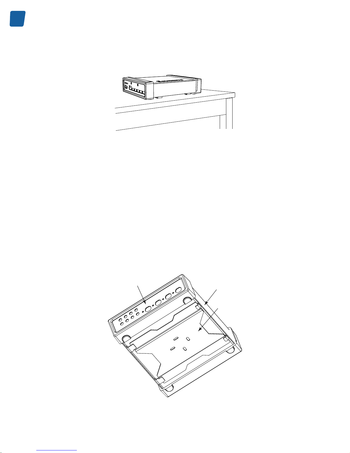
Desktop Mount
Picolo.net HD4 "Desktop"
The out-of-the box product, namely the Picolo.net HD4 "Desktop", is ready for a desktop usage. The baseplate and
the DIN-rail clip may be discarded.
The enclosure is designed in such a way that its bottom side faces the table. The four embossings on the bottom side
of the plastic caps act as anti-skid feet, and avoid direct contact between metallic parts and the table.
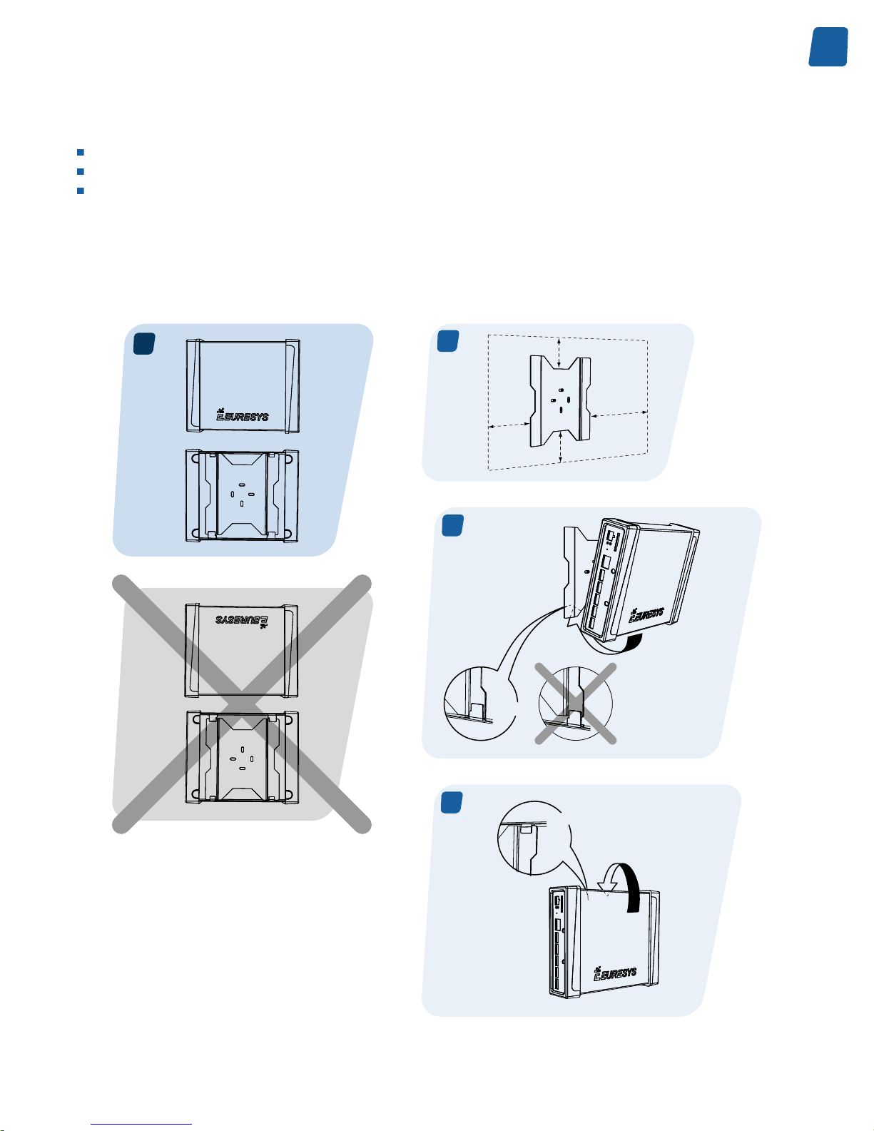
Wall Mount
The Picolo.net HD4 "Desktop" is used together with the baseplate. The DIN-rail clip may be discarded.
First of all, the baseplate has to be attached to the wall using appropriate fixation methods. Therefore it is equipped
with four oblong openings allowing easy installation and alignment. The openings dimensions are 4 mm x 12 mm
(0.16" x 0.47").
The enclosure is then hooked upon the baseplate by first inserting the long enclosure brackets, then the short brackets.
The four embossings on the bottom side of the plastic caps act as anti-skid feet, and prevent any movement of the
enclosure once hooked-up on the baseplate.
Front side
Enclosure
Baseplate
Enclosure on baseplate assembly
11
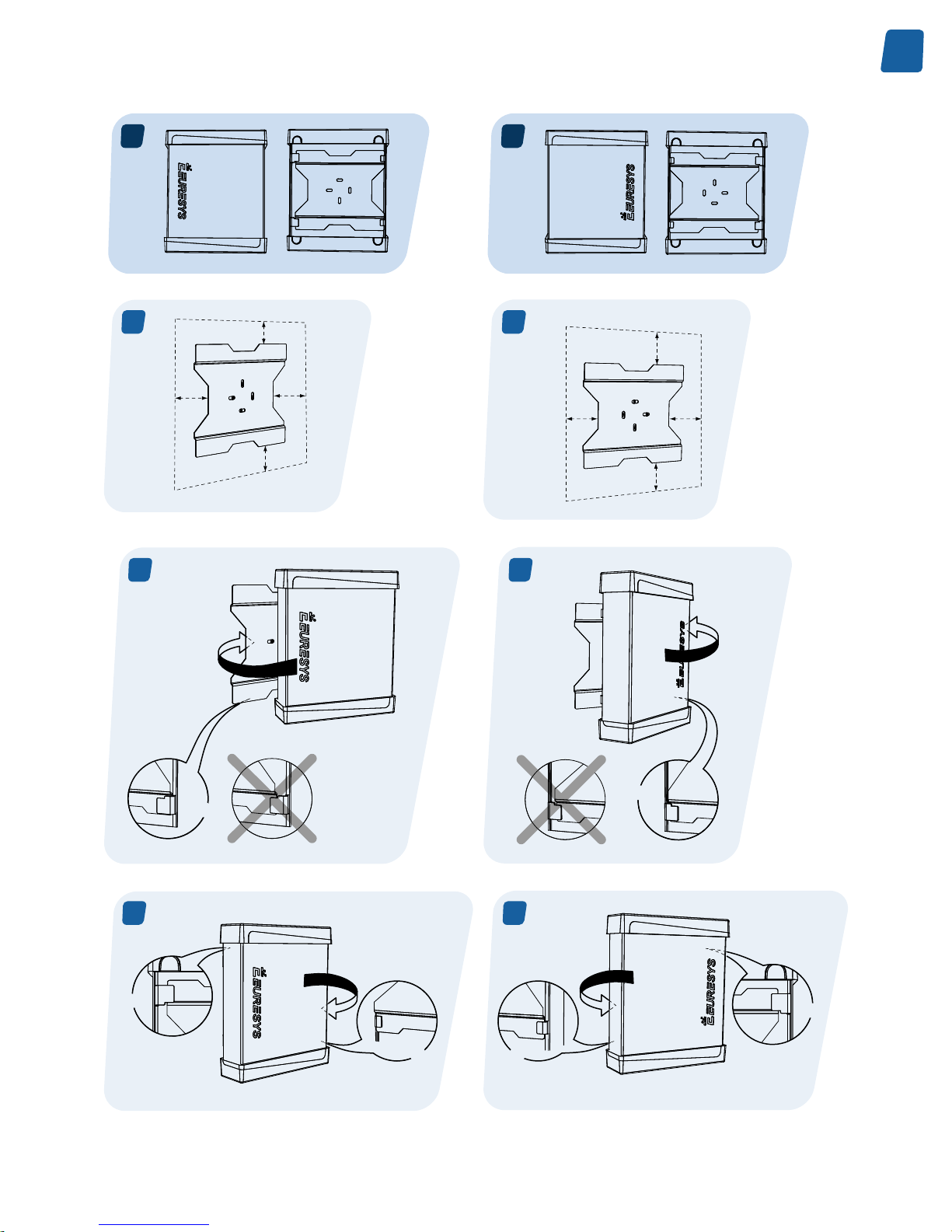
Mechanical Specification PC1656 Picolo.net HD4 Handbook
The enclosure and the baseplate are designed in such a way that the enclosure can be mounted on a vertical flat
surface with three possible orientations:
Horizontal: the BNC video connectors are facing rightwards and the Euresys logo is horizontal.
Vertical Downwards: the BNC video connectors and the Euresys logo are oriented downwards.
Vertical Upwards: the BNC video connectors and the Euresys logo are oriented upwards.
Note. BNC video connectors facing leftwards is not allowed.
Wall Mount - Horizontal Orientation
The following drawings summarize the installation instructions for the horizontal orientation:
A
38 mm 1.5’’
43 mm 1.7’’
100 mm
4’’
150 mm
6’’
A1
A2
2x
A3
2x
Wall mount - Horizontal

12
PC1656 Picolo.net HD4 Handbook Mechanical Specification
Note. The void area around the baseplate is required to allow easy installation and removal of the enclosure on the
baseplate, and easy wiring on both the rear and front sides.
Wall Mount - Vertical Orientations
The following drawings summarize the installation instructions for both vertical orientations:
13
Mechanical Specification PC1656 Picolo.net HD4 Handbook
B
C
B1
100 mm 4’’
43 mm 0.9’’
38 mm 0.7’’
150 mm 6’’
C1
150 mm 6’’
38 mm 0.7’’
43 mm 0.9’’
100 mm 4’’
C2
2x
B2
2x
B3
1x
2x
C3
1x
2x
Wall mount - Vertical
14
PC1656 Picolo.net HD4 Handbook Mechanical Specification
Note. The void area around the baseplate is required to allow easy installation and removal of the enclosure on the
baseplate, and easy wiring on both the rear and front sides.
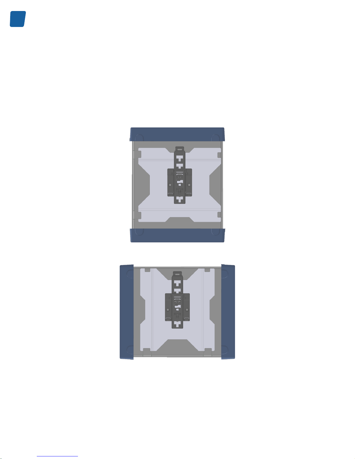
DIN-Rail Mount
To mount Picolo.net HD4 on a DIN rail, the DIN-rail clip must be installed on the back side of the baseplate, and the
enclosure must be hooked-up on the baseplate like for the wall-mount usage.
Assuming that the DIN rail is always horizontal, the DIN-rail clip must be oriented according to the desired orientations
for the BNC connectors.
DIN-rail clip orientation, for BNC video connectors facing upwards or downwards
DIN-rail clip orientation, for BNC video connectors facing rightwards
(BNC video connectors facing leftwards is not allowed)
The DIN-rail clip is equipped with a lever that facilitates the removal from the DIN rail.
15
Mechanical Specification PC1656 Picolo.net HD4 Handbook
Connectors, LED Indicators, and Switches
Location and Markings
Front panel layout
HDcctv 1.0
Input 1 Input 2 Input 3 Input 4
Present Present PresentPresent
Picolo.net HD4
HDcctv 1.0
Input 1
1
2
1 2
3
4
3 4
Input 2
AUDIO Inputs
AUDIO Outputs
Input 3 Input 4
Present Present PresentPresent
Picolo.net HD4 with 2 Audio Module options
Rear panel layout
Power
Ready
SHLD
GND
485A
485B
POWER
12-24V 25W Max
10/100/1000
+
-
LAN
COM
IN1A
IN1B
IN2A
IN2B
ALARM
IN3A
IN3B
IN4A
IN4B
R1A
R1B
R2A
R2B
RELAY
R3A
R3B
R4A
R4B
Picolo.net HD4 rear panel layout
16
PC1656 Picolo.net HD4 Handbook Mechanical Specification
Connectors
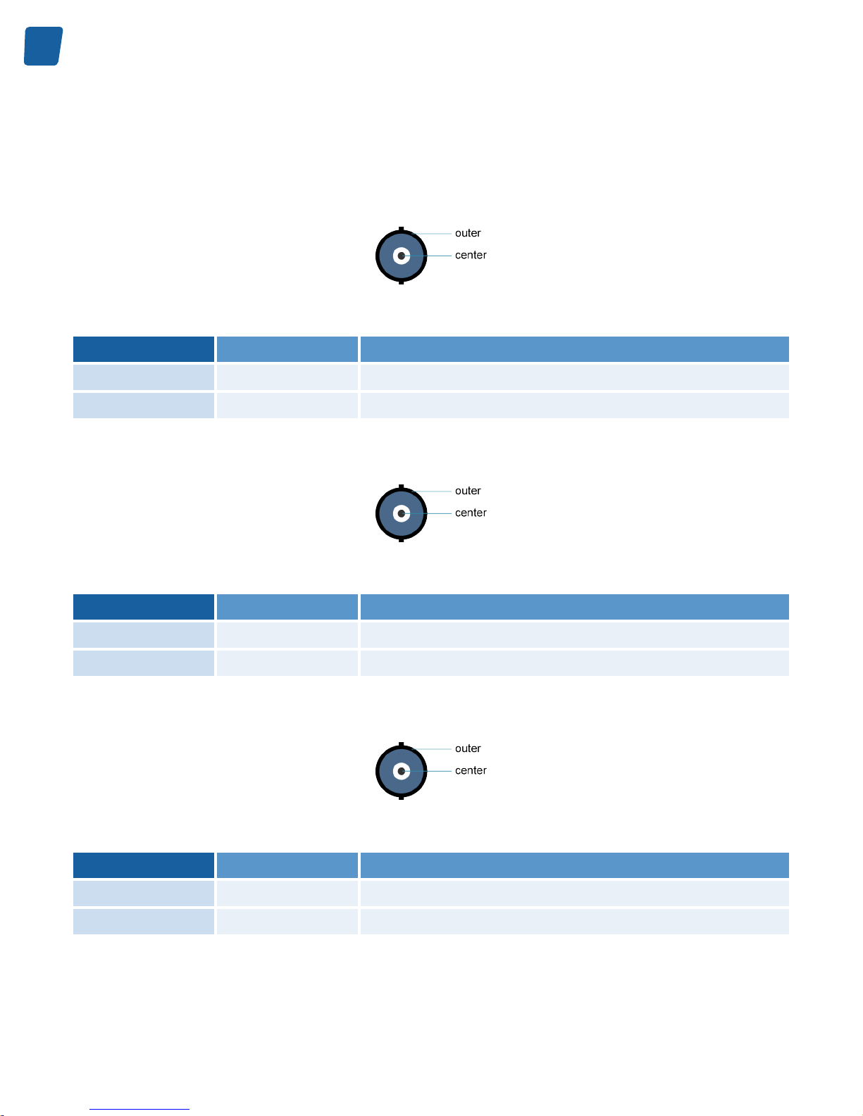
HDcctv Input 1 Connector
2-pin female receptacle, right-angled PCB-mount, BNC connector
Pin
Signal Usage
Center
HDcctv IN1 HDcctv input 1
Outer
GND Chassis ground
HDcctv Input 2 Connector
2-pin female receptacle, right-angled PCB-mount, BNC connector
Pin
Signal Usage
Center
HDcctv IN2 HDcctv input 2
Outer
GND Chassis ground
HDcctv Input 3 Connector
2-pin female receptacle, right-angled PCB-mount, BNC connector
Pin
Signal Usage
Center
HDcctv IN3 HDcctv input 3
Outer
GND Chassis ground
17
Mechanical Specification PC1656 Picolo.net HD4 Handbook
HDcctv Input 4 Connector
2-pin female receptacle, right-angled PCB-mount, BNC connector
Pin
Signal Usage
Center
HDcctv IN4 HDcctv input 4
Outer
GND Chassis ground
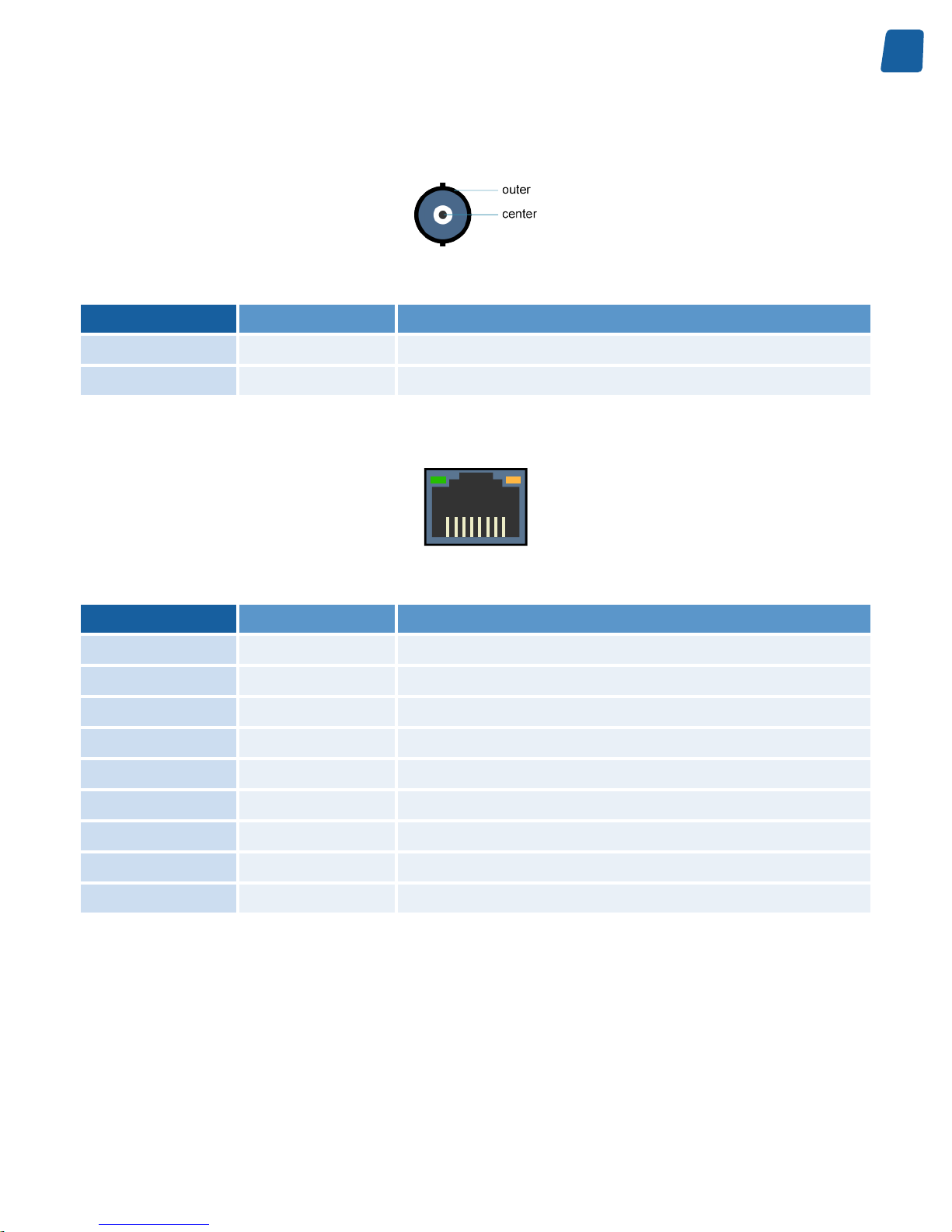
LAN Connector
1 8
8-pin RJ45 jack connector with 2 built-in LED indicators
Pin
Signal Usage
1
TRP1+ Transmit/Receive Pair 1 +
2
TRP1- Transmit/Receive Pair 1 -
3
TRP2+ Transmit/Receive Pair 2 +
4
TRP3+ Transmit/Receive Pair 3 +
5
TRP3- Transmit/Receive Pair 3 -
6
TRP2- Transmit/Receive Pair 2 -
7
TRP4+ Transmit/Receive Pair 4 +
8
TRP4- Transmit/Receive Pair 4 -
Shell
GND Chassis ground
18
PC1656 Picolo.net HD4 Handbook Mechanical Specification
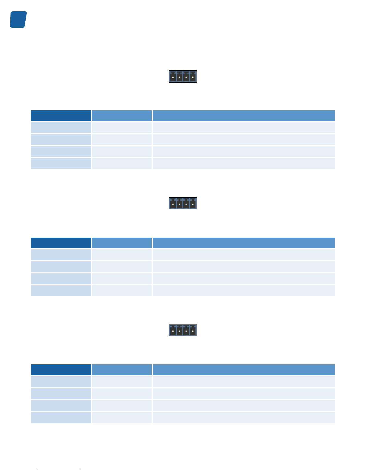
COM Connector
1
2 3
4
4-pin 3.5mm pitch terminal socket
Pin
Signal Usage
1
SHLD Chassis ground
2
GND Signal ground
3
485+ Transmit/Receive - Positive terminal
4
485- Transmit/Receive - Negative terminal
ALARM I Connector
1
2 3
4
4-pin 3.5mm pitch terminal socket
Pin
Signal Usage
1
IN1A Alarm Input 1 - Terminal A
2
IN1B Alarm Input 1 - Terminal B
3
IN2A Alarm Input 2 - Terminal A
4
IN2B Alarm Input 2 - Terminal B
ALARM II Connector
1
2 3
4
4-pin 3.5mm pitch terminal socket
Pin
Signal Usage
1
IN3A Alarm Input 3 - Terminal A
2
IN3B Alarm Input 3 - Terminal B
3
IN4A Alarm Input 4 - Terminal A
4
IN4B Alarm Input 4 - Terminal B
19
Mechanical Specification PC1656 Picolo.net HD4 Handbook
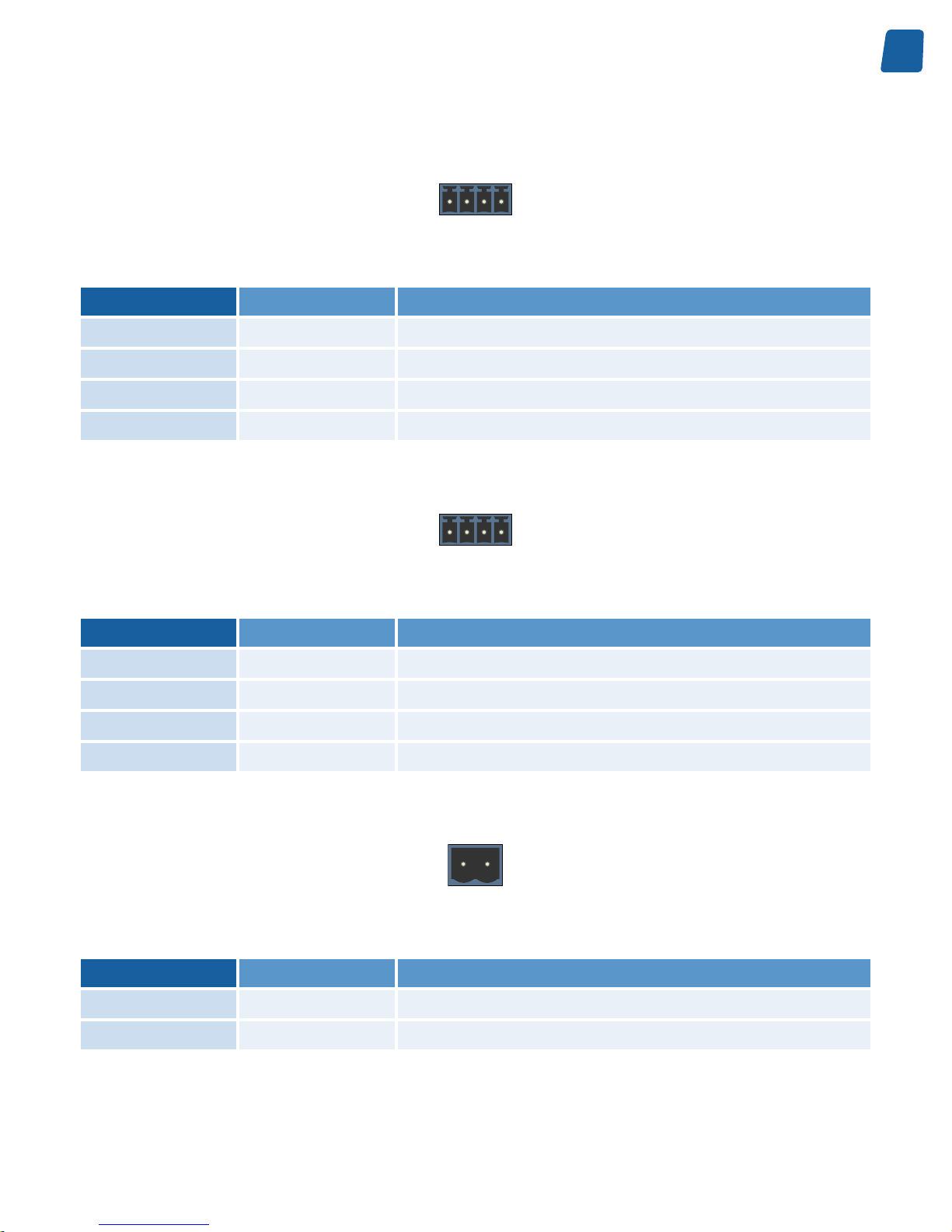
RELAY I Connector
1
2 3
4
4-pin 3.5mm pitch terminal socket
Pin
Signal Usage
1
R1A Relay Output 1 - Terminal A
2
R1B Relay Output 1 - Terminal B
3
R2A Relay Output 2 - Terminal A
4
R2B Relay Output 2 - Terminal B
RELAY II Connector
1
2 3
4
4-pin 3.5mm pitch terminal socket
Pin
Signal Usage
1
R3A Relay Output 3 - Terminal A
2
R3B Relay Output 3 - Terminal B
3
R3A Relay Output 4 - Terminal A
4
R3B Relay Output 4 - Terminal B
POWER Connector
1
2
2-pin 5mm pitch terminal socket
Pin
Signal Usage
1
+ DC Power Input - Positive terminal
2
- DC Power Input - Negative terminal
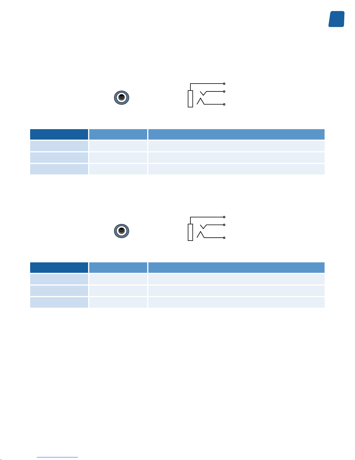
Audio Input 1 Connector
This connector is optional.

20
PC1656 Picolo.net HD4 Handbook Mechanical Specification
Sleeve
Tip
Ring
Black TRS 3.5mm jack socket connector
Pin
Signal Usage
Ring
- Unused
Tip
AUDIO IN1 Analog audio input 1
Sleeve
GND Chassis ground
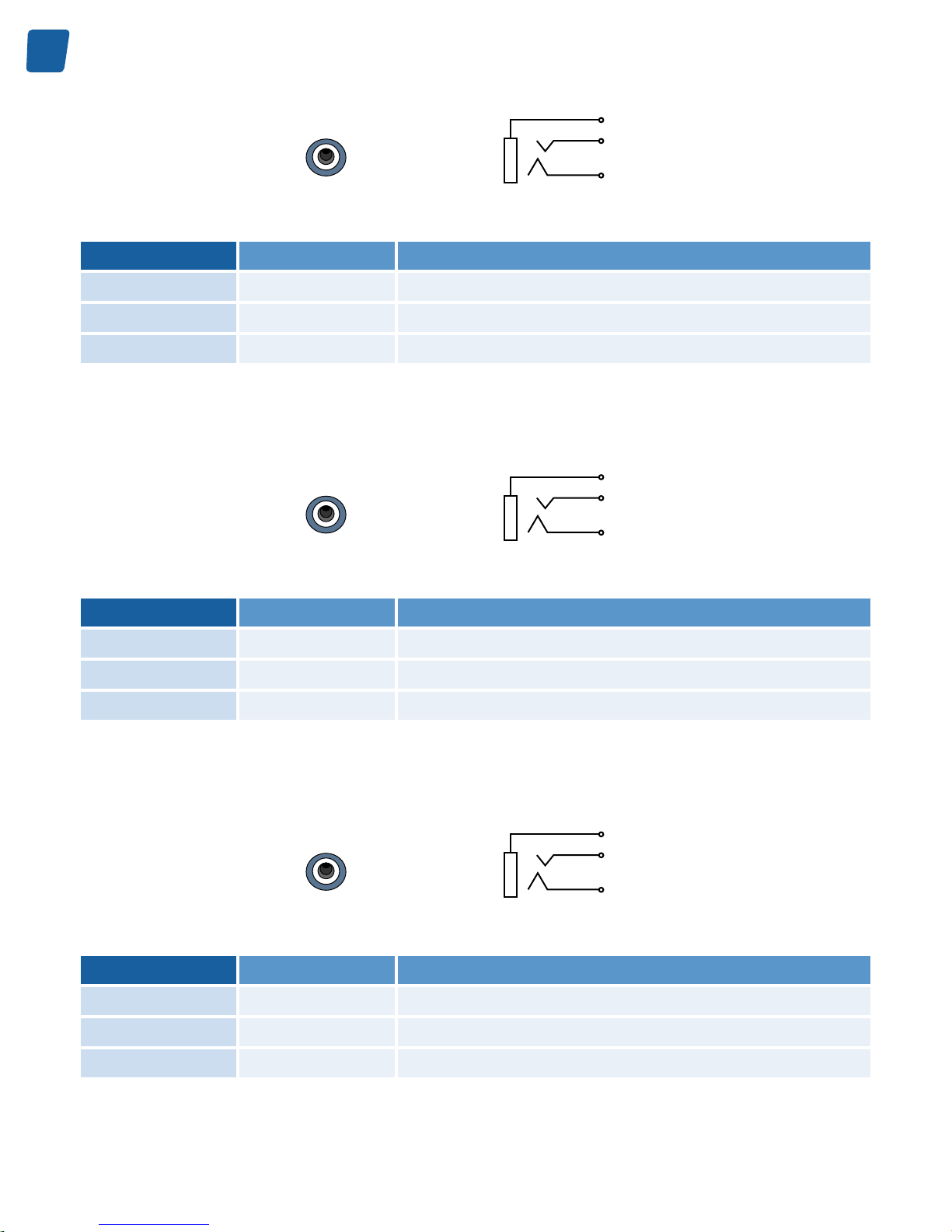
Audio Input 2 Connector
This connector is optional.
Sleeve
Tip
Ring
Black TRS 3.5mm jack socket connector
Pin
Signal Usage
Ring
- Unused
Tip
AUDIO IN2 Analog audio input 2
Sleeve
GND Chassis ground
Audio Input 3 Connector
This connector is optional.
Sleeve
Tip
Ring
Black TRS 3.5mm jack socket connector
Pin
Signal Usage
Ring
- Unused
Tip
AUDIO IN3 Analog audio input 3
Sleeve
GND Chassis ground
21
Mechanical Specification PC1656 Picolo.net HD4 Handbook
Audio Input 4 Connector
This connector is optional.
Sleeve
Tip
Ring
Black TRS 3.5mm jack socket connector
Pin
Signal Usage
Ring
- Unused
Tip
AUDIO IN4 Analog audio input 4
Sleeve
GND Chassis ground
Audio Output 1 Connector
This connector is optional.
Sleeve
Tip
Ring
Black TRS 3.5mm jack socket connector
Pin
Signal Usage
Ring
- Unused
Tip
AUDIO OUT1 Analog audio output 1
Sleeve
GND Chassis ground
Audio Output 2 Connector
This connector is optional.
22
PC1656 Picolo.net HD4 Handbook Mechanical Specification
Sleeve
Tip
Ring
Black TRS 3.5mm jack socket connector
Pin
Signal Usage
Ring
- Unused
Tip
AUDIO OUT2 Analog audio output 2
Sleeve
GND Chassis ground
Audio Output 3 Connector
This connector is optional.
Sleeve
Tip
Ring
Black TRS 3.5mm jack socket connector
Pin
Signal Usage
Ring
- Unused
Tip
AUDIO OUT3 Analog audio output 3
Sleeve
GND Chassis ground
Audio Output 4 Connector
This connector is optional.
Sleeve
Tip
Ring
Black TRS 3.5mm jack socket connector
Pin
Signal Usage
Ring
- Unused
Tip
AUDIO OUT4 Analog audio output 4
Sleeve
GND Chassis ground

23
Mechanical Specification PC1656 Picolo.net HD4 Handbook
LED Indicators and Switches
LED indicators
Picolo.net HD4 LED indicators
Location Type and Colour Marking Function
Front panel Circular green LED HDcctv Input 1 Present HDcctv/HD-SDI signal status
Front panel Circular green LED HDcctv Input 2 Present HDcctv/HD-SDI signal status
Front panel Circular green LED HDcctv Input 3 Present HDcctv/HD-SDI signal status
Front panel Circular green LED HDcctv Input 4 Present HDcctv/HD-SDI signal status
Rear panel Circular green LED Power Power status
Rear panel Circular green LED Ready Device status
Rear panel - LAN connector Rectangular green LED No marking Link activity
Rear panel - LAN connector Rectangular amber LED No marking Link status
HDcctv/HD-SDI Signal Status LED State Meaning
LED State Meaning
OFF No or invalid HDcctv / HD-SDI signal
ON Valid and supported HDcctv / HD-SDI signal
Blink 1Hz 90% ON time Valid but unsupported HDcctv / HD-SDI signal
Power Status LED State Meaning
LED State Meaning
OFF No power
ON Power OK

24
PC1656 Picolo.net HD4 Handbook Mechanical Specification
Device Status LED State Meaning
LED State Meaning
OFF Power OFF or Operating System kernel startup
Fast blink (10 Hz) 50% ON time Operating System Kernel startup completed, system boot in
progress
ON System is Ready
Slow blink (1 Hz) 10% ON time Firmware update in progress
Slow blink (1 Hz) 90% ON time System error
LAN Link Activity LED State Meaning
LED State Meaning
OFF No activity on the link
Blink Activity on the link
LAN Link Status LED State Meaning
LED State Meaning
OFF The link is not OK
Blink The link is OK and operating at the lowest speed
ON The link is OK and operating at the highest speed
Switches
Picolo.net HD4 Switches
Location Type Marking Function
Rear panel Recessed push-button No marking Device maintenance
Device Maintenance Switch Action Meaning
Switch Action Meaning
Short push (200 ms < t < 3 s) Reboot the device
Long push (t > 3 s) Restore the device factory settings including network settings
25
Electrical Specification PC1656 Picolo.net HD4 Handbook
Electrical Specification
Power Input
Picolo.net HD4 is powered from an external single voltage DC power source.
Operating characteristics
Operating characteristics
Min. Typ. Max. Unit
Voltage range (pre-series devices)
9.6 14.4 V
Voltage range (full-spec devices)
8 40 V
Power consumption – normal operation
15 W
Note. Pre-series products, SN00011 up to SN00070, are restricted for use with 12V DC supply!
Note. The input voltage range enables the usage of:
Unregulated 12V DC +/- 20 % supply sources on all devices including pre-series devices.
Unregulated 12V DC and 24V DC +/- 25 % supply source on full-spec devices.
Note. The Power input connector is labeled 12 V for pre-series devices and 12-24 V for full-spec devices.
Absolute maximum ratings
Absolute maximum ratings
Min. Typ. Max. Unit
Forward voltage
***TBD*** V
Reverse voltage
***TBD*** V
Note. The specification applies to the whole operating temperature range.
Note. Exceeding the above limits may irreversibly damage Picolo.net HD4.
HD-SDI / HDcctv 1.0 Inputs
Picolo.net HD4 has 4 identical HDcctv 1.0 compliant inputs. The inputs are also electrically compatible with HD-SDI
(high-definition serial digital interface) compliant video sources.
26
PC1656 Picolo.net HD4 Handbook Electrical Specification
Operating characteristics
Operating characteristics
Min. Typ. Max. Unit
Peak-to-peak signal amplitude (short cable)
720 800 950 mV
Serial data rate
1.485 Gbps
PLL loop filter bandwidth
1.5 MHz
Achievable cable length with Belden 1694 coaxial cable
100 m
Input impedance
75 Ω
Return loss measured over the 5MHz to 2.25GHz
frequency range
-15 dB
Absolute maximum ratings
Absolute maximum ratings
Min. Typ. Max. Unit
DC voltage
-2.0 +2.0 V
Note. Exceeding the above limits may irreversibly damage Picolo.net HD4. The usage of DC-coupled video sources
outside the above mentioned limits is strictly prohibited.
COM I/O
Picolo.net HD4 has 1 bi-directional RS-485 compatible COM port.
Operating Characteristics
Operating characteristics
Operating characteristics
Min. Typ. Max. Unit
Termination load impedance
120 Ω
Driver differential output voltage
1.5 V
ptp
Receiver common-mode voltage range
-7 +12 V
ESD voltage rating
15 kV
Condition: the RS-485 line is terminated at both ends with 120 ohms.
27
Electrical Specification PC1656 Picolo.net HD4 Handbook
Absolute Maximum Ratings
Absolute maximum ratings
Absolute maximum ratings
Min. Typ. Max. Unit
DC voltage
-8 +13 V
Driver output current
250 mA
Note. Exceeding the above limits may irreversibly damage Picolo.net HD4.
Alarm Inputs
Picolo.net HD4 has 4 identical Alarm Input ports.
Each of those digital non-isolated differential input ports exposes two pins named INxA and INxB respectively, where
x is a number ranging from 1 to 4.
The ports are insensitive to the polarity and support the direct connection of the following types of devices:
Potential-free contact closure (a.k.a. dry contacts)
Fixed potential contact closure (one pin of the contact at a fixed potential)
Digital Totem-Pole drivers operating at TTL, 3V CMOS, 5V CMOS, and 12V CMOS levels
Possible state values for contact closure devices:
State Description
OPEN The contact is open.
LOW The contact is closed.
Possible state values for logical devices:
State Description
OPEN Logical device is in High-Z.
LOW Logical device is driving LOW.
HIGH Logical device is driving HIGH.
Related Links
System Integration Specifications on page 44
ONVIF Device IO Service on page 56
The Device IO service offers commands to retrieve and configure the settings of physical inputs and outputs of a
device.
Proprietary Device IO service on page 57
The proprietary Device IO service extends the ONVIF Device IO service.
28
PC1656 Picolo.net HD4 Handbook Electrical Specification
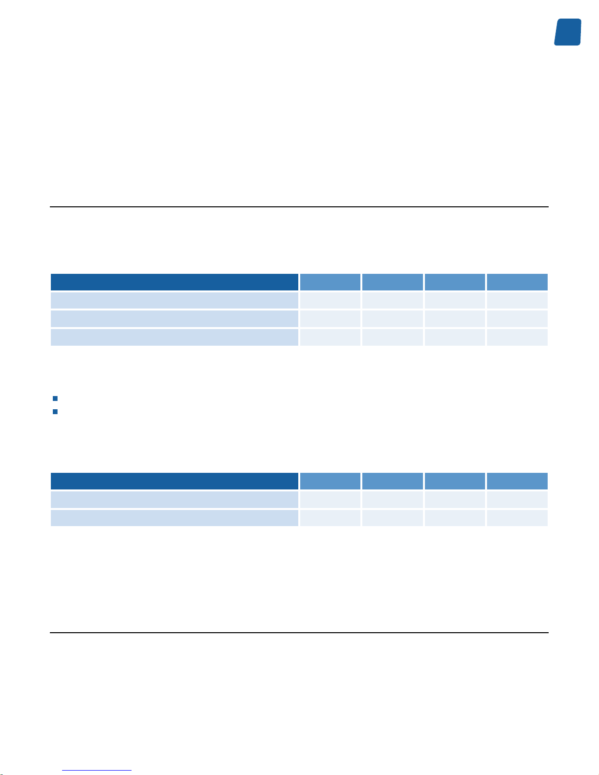
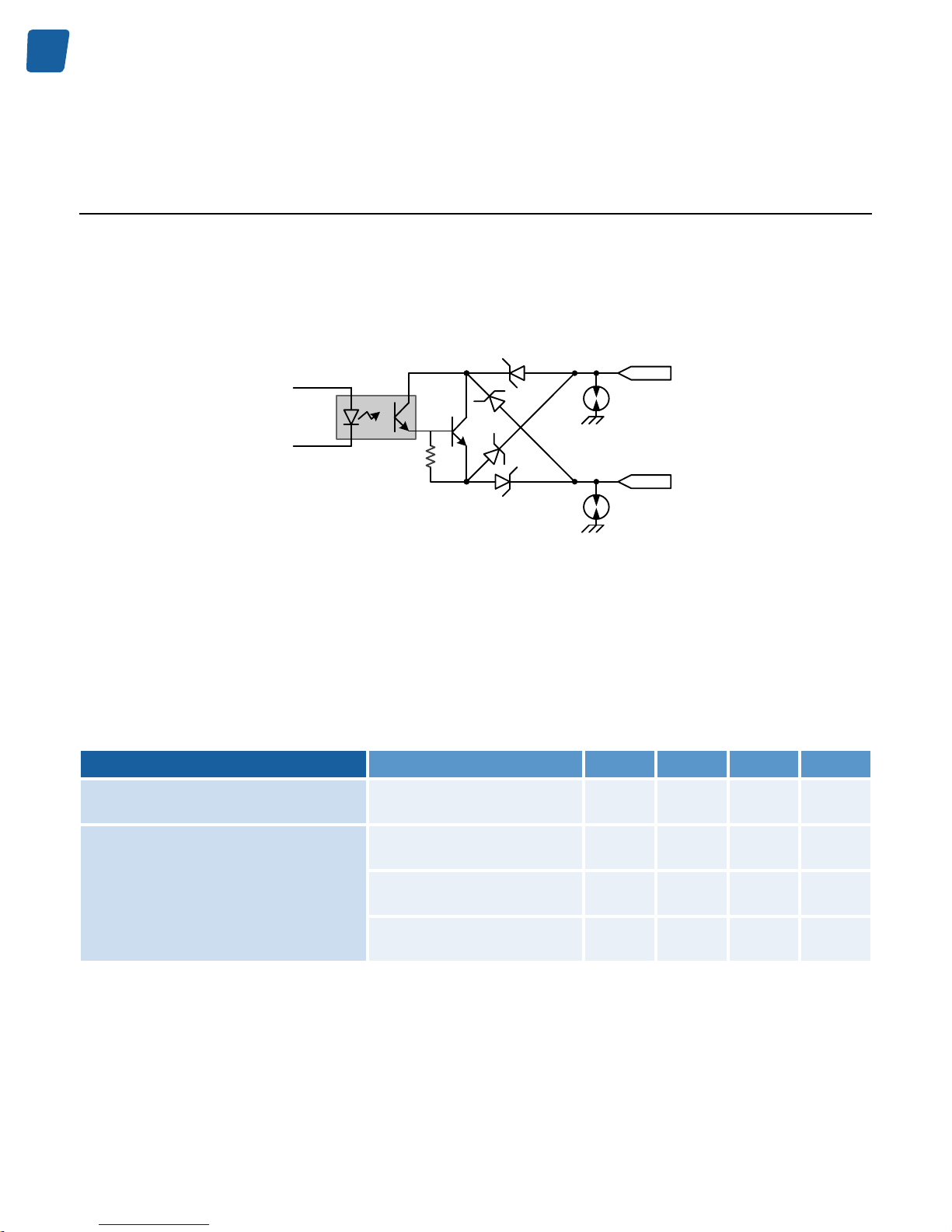
Relay Outputs
Picolo.net HD4 has 4 identical Relay Output ports.
Each port has two pins named RxA and RxB respectively, where x is a number ranging from 1 to 4.
This output port emulates a potential-free and polarity-free solid-state contact. It is capable of switching both AC- and
DC-powered resistive loads.
RxA
RxB
From I/O
controller
Opto
coupler
Relay Output port schematic
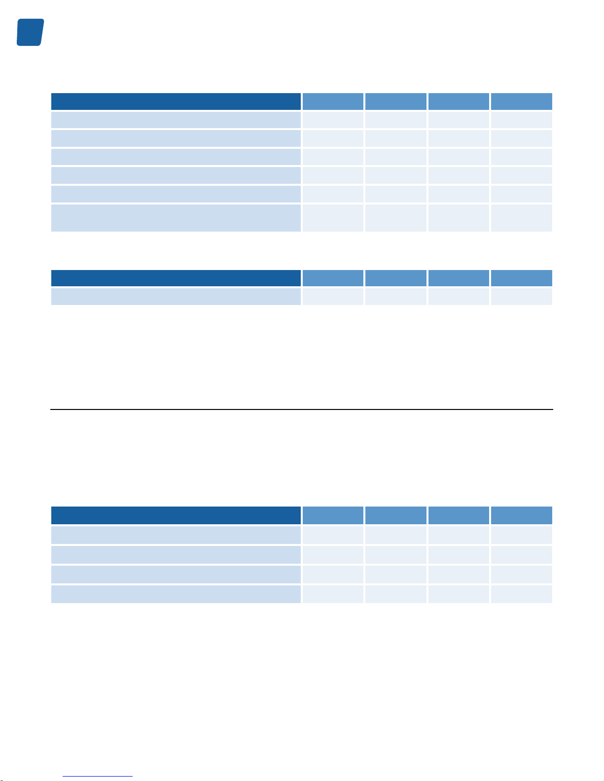
The contact remains in the OPEN state during the board initialization procedure.
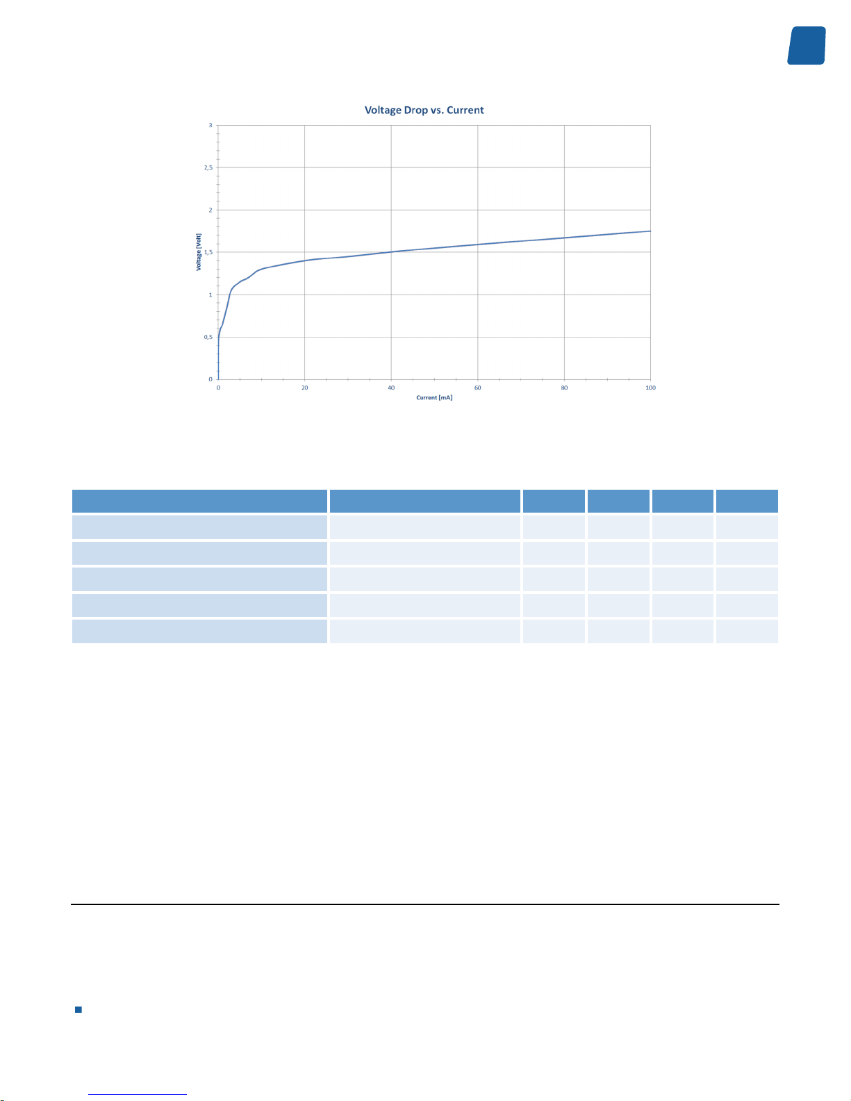
In the CLOSED state, the output port exhibit a voltage drop across its pins. Typical voltage drops for current values
of 1, 10 and 100 mA are shown in the following table:
Operating the relay output with load currents below 1 mA is not recommended since it exhibit a large equivalent
resistance!
Operating Characteristics
Operating Characteristics
Condition Min. Typ. Max. Unit
Load Current - Recommended range
Ambient temperature up to 55
°C
1 10 100 mA
1 mA; 25 °C ambient
temperature
0.65 V
10 mA; 25 °C ambient
temperature
1.3 V
Voltage across pins
100 mA; 25 °C ambient
temperature
1.75 V
29
Electrical Specification PC1656 Picolo.net HD4 Handbook
Relay Output port U-I diagram
Absolute Maximum Ratings
Absolute Maximum Ratings Test Condition Min. Typ. Max. Unit
Absolute maximum DC voltage
Contact open -30 +30 V
Absolute maximum AC voltage
Contact open 21 V
RMS
Absolute maximum DC current
Contact closed -100 +100 mA
Absolute maximum AC current
Contact closed 70 mA
RMS
Isolation voltage
500 V
RMS
Exceeding the absolute maximum ratings may irreversibly damage Picolo.net HD4.
Related Links
System Integration Specifications on page 44
ONVIF Device IO Service on page 56
The Device IO service offers commands to retrieve and configure the settings of physical inputs and outputs of a
device.
Proprietary Device IO service on page 57
The proprietary Device IO service extends the ONVIF Device IO service.
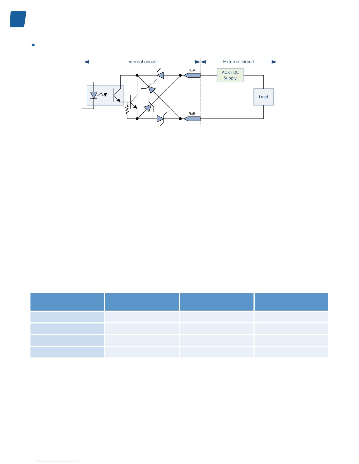
Using Relay Outputs
Circuit Diagram
The following drawing shows a diagram of an electrical circuit using one Picolo.net HD4 relay output. The left side
shows the simplified electric diagram of the relay output port; the right side shows the elements of the external circuit:
The power supply
30
PC1656 Picolo.net HD4 Handbook Electrical Specification
The load
Circuit Diagram
Power Supply
Operating the relay output circuit requires an external power source.
The power source can be either DC or AC since the relay output port is capable of switching current of both polarities.
The recommended voltage rating ranges from 5V up to 24V for DC supply and from 5V
RMS
up to 15V
RMS
for AC supply.
Load
The load impedance must be essentially resistive.
If the load is capacitive, it is necessary to insert a series resistor to prevent against excessive currents when the relay
output enters the CLOSED state.
If the load is inductive, it is necessary to insert a series resistor to prevent against excessive voltage spikes when
the relay output changes of state.
The recommended current rating ranges from 1 mA to 100 mA for the whole operating temperature range.
As shown on the following table, the range of allowed load resistance values depends on the selected supply voltage
and the load current limits.
Load Resistance Range vs. Supply voltage
Supply voltage Load Resistance - Bottom
Range @I = 100 mA
Load Resistance - Mid
Range @I = 10 mA
Load Resistance -
Top Range @I = 1 mA
5V DC or 5V
RMS
AC
33 Ohms 370 Ohms 4.35 kOhms
12V DC or 12V
RMS
AC
103 Ohms 1.07 kOhms 11.35 kOhms
15V DC or 15V
RMS
AC
133 Ohms 1.37 kOhms 14.35 kOhms
24VDC
223 Ohms 2.27 kOhms 23.35 kOhms
For instance, with a power supply of 12V DC or 12V
RMS
AC , the load resistance must be higher than 103 Ohms
and less than 11.35 kOhms.

31
Electrical Specification PC1656 Picolo.net HD4 Handbook
Audio Inputs
Audio Module for Picolo.net HD4 has 2 identical analog audio input ports.
Operating Characteristics
Operating characteristics
Min. Typ. Max. Unit
Full-scale input voltage
1.35 1.4 1.5 V
ptp
Input impedance (@ 1 kHz)
20 kΩ
Sampling frequency
48 kHz
Absolute Maximum Ratings
Absolute maximum ratings
Min. Typ. Max. Unit
DC voltage
-10 +10 V
Input signal level
2.0 V
ptp
Note. Exceeding the above limits may irreversibly damage Audio Module for Picolo.net HD4.

32
PC1656 Picolo.net HD4 Handbook Environmental Specification
Environmental Specification
Operating Conditions
The following requirements are applicable to Picolo.net HD4 during operating conditions:
Requirements
Requirement during operating conditions
Min. Max. Unit
0 +55 °C
Ambient air temperature range
+32 +131 °F
Ambient humidity range
10 90 % RH non-condensing
Dissipated power
Characteristic
Typ. Unit
51 BTU/h
Thermal value
15 W
Storage Conditions
The following requirements are applicable to Picolo.net HD4 during storage conditions when the product is not
operating:
Requirement during storage conditions
Requirement during storage conditions
Min. Max. Unit
-20 +70 °C
Temperature range
-4 +158 °F
Humidity range
10 90 % Relative Humidity
non-condensing

33
Environmental Specification PC1656 Picolo.net HD4 Handbook
Compliance
Electromagnetic
Picolo.net HD4 complies with:
The European Council EMC Directive 2004/108/EC
The Unites States FCC rule 47 CFR 15
It has been tested and found to comply with the following standards:
Radiated emission
Standard
Limit / Level
EN 55022
Class A
FCC 47 CFR 15 Sub-part A
Class A
Immunity
Standard
Description
EN 61000-4-3
Radiated, radio-frequency, electromagnetic field immunity test
EN 61000-4-4
Electrical fast transient/burst immunity test
EN 61000-4-5
Surge immunity test
EN 61000-4-6
Immunity to conducted disturbances, induced by radio-frequency fields
EN 61000-4-11
Voltage dips, short interruptions and voltage variations immunity tests
RoHS
Picolo.net HD4 is manufactured according to the European Union RoHS 2011/65/EU Directive.
WEEE
According the European 2002/96/EC Directive, Picolo.net HD4 must be disposed of separately from normal household
waste. It must be recycled according to the local regulations.

34
PC1656 Picolo.net HD4 Handbook Functional Specification
Functional Specification
Video Specifications
Video Processing Chain
The processing chain of Picolo.net HD4 is composed of the following elements:
4 video sources
4 scalers
12 H.264 encoders
The video source implements an HD-SDI receiver capable of automatically identifying and decoding 720p and 1080p
video signals at various frame rates. It delivers a full rate full resolution digital video stream to the source splitter.
The video splitter delivers up to 3 copies, possibly at a reduced frame rate, of the incoming digital video stream.
The scaler exclusively performs down-scaling of the video resolution.
The H.264 encoder performs the compression and delivers the encoded video stream.
Video Processing Capabilities
The capabilities of the video processing chain of Picolo.net HD4 are summarized as follows:
Up to 3 H.264 video streams per camera can be generated.
A total of up to 12 H.264 video streams can be generated per device.
The frame rate of all video streams is configurable individually.
The resolution of up to 4 video streams can be reduced.
The cumulated encoding power cannot exceed the equivalent of encoding 6 x 1080p30 video streams.
Programming Model
The application software manages the video processing resources using one ONVIF Media Profile for each encoded
video stream.
An ONVIF Media Profile associates one VideoSourceConfiguration and one VideoEncoderConfiguration.
The following simplified programming model applies to each video channel of Picolo.net HD4:

35
Functional Specification PC1656 Picolo.net HD4 Handbook
Video encoder #3
Encoded video bit stream #3
Video encoder #2
Encoded video bit stream #2
HD-SDI or
HDcctv 1.0 signal
Video source
Automatic format detection
Signal presence detection
Video encoder #1
Frame rate control
Encoded video bit stream #1
Resolution control
H.264 encoding
Programming model of a video channel of Picolo.net HD4
Video Source Specification
Picolo.net HD4 has 4 identical Video Sources.
Video Signal Requirement
The Video Source decodes the following high-definition video signals:
Video Signal Properties
Characteristics Description
Number and type
4 x HD-SDI (SMPTE 292M)
Data rate [Gbit/s]
1.485 and 1.485/1.001
Video standards
720p (SMPTE 296M) and 1080p (SMPTE 274M) progressive scan only
Native resolution
720p: 1280 x 720 lines; 1080p: 1920 x 1080 lines
Standard selection
Automatic
LED indicator
Video Presence
Status/Event reporting
Video Presence, Detected standard

36
PC1656 Picolo.net HD4 Handbook Functional Specification
720p Frame Rates
720p Frame Rate [fps] Data Rate [Gbit/s]
23.98 1.485/1.001
24 1.485
25 1.485
29.97 1.485/1.001
30 1.485
50 1.485
59.94 1.485/1.001
60 1.485
1080p Frame Rates
1080p Frame Rate [fps] Data Rate [Gbit/s]
23.98 1.485/1.001
24 1.485
25 1.485
29.97 1.485/1.001
30 1.485
Note. Picolo.net HD4 doesn't support interlaced formats.
Video Format Selection
The video format is automatically detected.
The actual frame rate and the resolution are reported into the FrameRate and Resolution properties of the ONVIF
VideoSource object.
Event Reporting
Video Signal Presence
Video Format Change Detected
Video Presence Detection
The presence of a valid Video Signal is reported by:
The "HDcctv Input Present" LED indicator
Generation of "Signal" event
A video signal is considered as valid when all the following conditions are met:
The signal timing complies with the above listed specification

37
Functional Specification PC1656 Picolo.net HD4 Handbook
No CRC errors are detected by the SDI receiver
Video Encoder Specification
Encoding Method
The following video encoding methods are available:
H.264
JPEG
H.264 Video Encoder Specification
Resolution
The H.264 encoder delivers images in one of the following resolutions:
H.264 Encoding Resolution
Width Height Short Name Image
Aspect Ratio
Remark
1920 1080 Full HD 16:9 Native for 1080p sources
1280 720 HD720 16:9 Native for 720p sources
960 540 qHD 16:9
640 360 16:9 Fits within a VGA display
480 270 16:9
320 240 QVGA 4:3 Available since version 4.x
320 180 16:9 Fits within a QVGA display
The default resolution setting is the native video source resolution:
1920 (H) x 1080 (V) for 1080p sources
1280 (H) x 720 (V) for 720p sources
Profile
The H.264 encoder supports the following H.264 encoding profiles:
H.264 Baseline profile
H.264 Main profile
H.264 High profile
The default encoding profile is the Baseline profile.

38
PC1656 Picolo.net HD4 Handbook Functional Specification
Rate Control - Frame Rate
The EncodingInterval and FrameRateLimit properties of the VideoEncoderConfiguration object determine the frame
rate of the encoded video stream:
FrameRateLimit is an integer value expressed in frames per second [fps] specifying the upper limit of the frame rate
of the encoded video stream.
On Picolo.net HD4, the FrameRateLimit property:
Is set, by default, to the actual frame rate of the video source.
Can be set to any integer value up to the frame rate of the video source.
Note. For video sources having a non-integer frame rate value, the default and maximum value of FrameRateLimit
is rounded up to the next integer value. For instance for 29.97 fps sources, FrameRateLimit is set to 30
Setting FrameRateLimit to 0 is equivalent to setting FrameRateLimit to its maximum value.
EncodingInterval specifies the interval between encoded frames. A value of 1 means that all frames are encoded;
a value of 2 means that 1 frame out of 2 are effectively encoded.
On Picolo.net HD4, the FrameRateLimit property:
Is set, by default, to 1.
Can be set to any integer value in the range [1, 150].
The frame rate of the encoded stream can be evaluated using the following formula:
Encoded Stream Frame Rate [fps] = FrameRateLimit / EncodingInterval
Rate Control - Bit Rate
The target bit rate is specified in kbps by the BitRateLimit property of the VideoEncoderConfiguration object.
On Picolo.net HD4, the BitRateLimit property:
Is set, by default, to 4000 kbps.
Can be set to any integer value up to 20000 kbps.
Note. Setting too low bit rates may result in lower fidelity, blocky or jerky video.
Picolo.net HD4 supports the following bit rate control methods:
CBR (Constant Bit Rate)
VBR (Variable Bit Rate)
The encoding quality is specified by the BitrateLimit property of the VideoEncoderConfiguration object.
GOP Size
The property GovLength specifies the total number of frames in a group of video pictures. Possible values are ranging
from 1 to 300; the default setting is 100.
In the H.264 Baseline profile, a Group of video is composed of one I(or IDR)-frame followed by (Govlength-1) P frames.
In the H.264 Main and High profiles, a Group of video is composed of one I(or IDR)-frame followed by (Govlength-1)
P or B frames.
Setting GovLength to 1 forces all pictures to be coded as I(or IDR)-frames.

39
Functional Specification PC1656 Picolo.net HD4 Handbook
JPEG Video Encoder Specification
Resolution
The JPEG encoder delivers images in one of the following resolutions:
JPEG Encoding Resolution
Width Height Short Name Image Aspect Ratio Remark
1920 1080 Full HD 16:9 Native for 1080p
sources
1280 720 HD720 16:9 Native for 720p
sources
960 540 qHD 16:9
640 360 16:9 Fits within a VGA
display
480 270 16:9
320 240 QVGA 4:3 Available since version
4.x
320 180 16:9 Fits within a QVGA
display
The default resolution setting is the native video source resolution:
1920 (H) x 1080 (V) for 1080p sources
1280 (H) x 720 (V) for 720p sources
Rate Control
The frame rate, bit rate and quality settings of MJPEG video encoders are ignored. The MJPEG video frame rate is low
(typically around 1 fps) and mainly depends on the amount of active JPEG encoders and their configured resolutions.
Audio Specifications
Picolo.net HD4 can be fitted with one or two Audio Module for Picolo.net HD4.
Each Audio Module for Picolo.net HD4 provides Picolo.net HD4 with the following capabilities:
Streaming encoded digital audio from each of the two analog audio input ports
Audio Inputs
Each audio input channel is composed of:

40
PC1656 Picolo.net HD4 Handbook Functional Specification
The audio source interface that digitizes the analog audio signal
The audio encoder that encodes the digital audio signal and performs the time-stamping
Source interface
Characteristics
Description
Number of analog audio input ports
2 single-channel
Type
Line-level analog inputs
Level control
Fixed
Sampling rate
Fixed: 48 kHz
Audio encoder
Characteristics
Description
Encoding standard
PCM G.711 µ-law
Bit rate
64 kbps (8-bit @ 8 kHz)
Time stamping resolution
11.1 microseconds (90 kHz time clock)
Audio streaming
One single-channel audio streams per audio input, individually configurable
Streaming Specifications
Media Transport Protocols
Media Transport Protocol
Picolo.net HD4 uses the Real-Time Transport Protocol - RTP - norm for streaming media data over the network. In
fact, the norm - RFC 3550 - describes two protocols:
The RTP protocol itself.
The Real-time Transport Control Protocol - RTCP.
The RTP protocol is a simple protocol which defines a standardized packet format for delivering audio and video
over IP networks.
The RTCP protocol provides statistics and control information over the RTP stream.
RTP is used extensively in communication and entertainment systems that involve streaming media.
RTP can be declined in various flavors, depending on the following choices:
The transport modality of the RTP stream over the network.
The type of media transported by the RTP stream.

41
Functional Specification PC1656 Picolo.net HD4 Handbook
Media Transport Control Protocol
Picolo.net HD4 uses the Real-time Streaming Protocol - RTSP - as the control protocol for all the flavors of RTP
streams.
RSTP is described by RFC 2326. It allows controlling another protocol (usually RTP), implementing commands such
as Play (start a stream), Pause (pause a stream) and Describe (describe the streams controlled by the current RTSP
session).
RTSP uses TCP as its transport protocol.
RTP Transport Modalities
Picolo.net HD4 implements the following modalities to transport the RTP stream over an IP network:
RTP over UDP Unicast
In this modality, the RTP stream is sent using the User Datagram Protocol - UDP - described in RFC 768.
The UDP protocol is a "fire and forget" protocol. The sender sends the data through the network and doesn't care
whether that data arrives to the client or not. The data is never resent, and thus can be lost if a problem happens
during the transport.
In the Unicast mode, the sender sends the data to a single receiver.
RTP over UDP MultiCast
This modality is almost identical to the "RTP over UDP Unicast" case. The only difference is that the data is sent to
multiple receivers instead of a single one using UDP multicasting.
UDP multicasting uses the "IP multicast" technique described in RFC 1112.
In this technique, the sender sends the data to a special multicast address. The data is then sent by the routing
protocols to receivers that previously informed the network that they are interested in the given multicast address. IP
multicast is thus a subscription-based technique.
RTP interleaved in RTSP over HTTP
This modality is almost identical to the "RTP interleaved in RTSP over TCP" modality. The only difference is that
instead of being directly sent on the TCP stream, the RTP and RTSP packets are first encapsulated in HTTP.
HTTP being a widely used protocol over the internet, encapsulating the data inside HTTP allows it to pass through
firewalls.
Since HTTP is based on TCP, this modality can also be categorized as reliable.
RTP Transport Media Types
RTP can transport different media types, each coming with a corresponding sub-norm of RTP.
Picolo.net HD4 implements the following sub-norms of RTP:
RTP Payload Format for H.264 Video
The RFC 3984 describes the methodology used to encapsulate H264 (MPEG-4 Part 10) data in a RTP stream.

42
PC1656 Picolo.net HD4 Handbook Functional Specification
RTP Payload Format for JPEG-compressed Video
The RFC 2435 describes the methodology used to encapsulate JPEG-compressed Video data in a RTP stream.
Network Specifications
Network
Characteristics
Description
LAN interface
1 x Ethernet 10BASE-T/100BASE-TX/1000BASE-T, automatic speed negotiation
LAN connector
1 x RJ45 with Link and Activity LED indicators
Application layer protocols
DHCP, DNS, HTTP, HTTPS, NTP,RTCP, RTP, RTSP, TLS 1.0
Transport layer protocols
TCP, UDP
Internet layer protocols
IPv4, ICMP, IGMPv2
IP Address Allocation Methods
Picolo.net HD4 provides the following methods to allocate the IP address to the LAN interface:
DHCP method - Automatic IPv4 address allocation using the Dynamic Host Configuration Protocol
LLA method - Automatic IPv4 address allocation using the Link Local Address method a.k.a. ZeroConfig method
Static IP method - Manual IPv4 address allocation
DHCP method
The DHCP method is an automatic IP address allocation method: the unique IP address is automatically assigned
by a DHCP Server.
At Power On, providing that the "DHCP method" is Enabled, the Picolo.net HD4 repeatedly attempts to contact the
DHCP Server.
This method requires a correctly configured and running DHCP Server on the same network. More specifically:
The DHCP Server must have sufficient IP addresses to deliver.
When the DHCP Server uses MAC address filtering, it is mandatory to add the MAC address of Picolo.net HD4
to the list of enabled MAC addresses on the DHCP Server.
The DHCP method is Enabled for an out-of-the-box product or after completion of the "Restore Factory Settings"
procedure.
If required, the DHCP method can be Disabled by changing the IP settings of Picolo.net HD4.
LLA method
The LLA method is an automatic IP address allocation method that doesn't require a DHCP Server providing that
all the peer device(s) are configured for LLA or ZeroConfig.
Note. LLA and ZeroConfig are widely supported by the Windows and Linux operating systems.

43
Functional Specification PC1656 Picolo.net HD4 Handbook
At Power On, providing that the "LLA method" is Enabled, the Picolo.net HD4 negotiates with the peer device(s) a
unique IP address in the 169.254.0.0/16 special block of IPv4 addresses reserved for that purpose.
The LLA method is Enabled for an out-of-the-box product or after completion of the "Restore Factory Settings"
procedure.
LLA and DHCP share a common enable/disable setting.
Static IP method
With the Static IP Method, the IP address is assigned by the user.
The Static IP method is Disabled for an out-of-the-box product or after completion of the "Restore Factory Settings"
procedure.
To manually assign a static IP address to Picolo.net HD4, the user must:
Establish a network session using any of the automatic IP address allocation method
Gain access to the device Web Pages, and select the Device Network tab of the Management page
Disable the automatic IP Address allocation by unchecking the "From DHCP" check-box in the IP Address panel
Fill-in the IP and Subnet Mask fields with the appropriate value
Apply the changes by clicking on the Apply button
Reboot the device
TLS Protocol
Picolo.net HD4 implements TLS 1.0 as described by RFC 2246.
The TLS protocol uses a hybrid encryption scheme, using a public-key algorithm to exchange securely between the
server and the client a session key. That key is then used by a symmetric key algorithm to encrypt and decrypt the
subsequent messages.
The combination of HTTP and TLS is more widely known as HTTPS.

44
PC1656 Picolo.net HD4 Handbook Functional Specification
System Integration Specifications
System integration
Characteristics Description
Application Programming Interface
ONVIF Profile S + Proprietary web services
Alarm inputs
4 x non-isolated polarity insensitive inputs for closing contacts or electronic sensor
with CMOS digital outputs
Alarm inputs connector
2 x removable plug with 4 push-in terminals
Relay outputs
4 x potential-free normally open contacts
Relay outputs connector
2 x removable plug with 4 push-in terminals
COM
1 x RS-485 bidirectional
COM connector
1 x removable plug with 4 push-in terminals
Pan/Tilt/Zoom protocol
Pelco D
Related Links
Alarm Inputs on page 27
ONVIF Device IO Service on page 56
The Device IO service offers commands to retrieve and configure the settings of physical inputs and outputs of a
device.
Proprietary Device IO service on page 57
The proprietary Device IO service extends the ONVIF Device IO service.
ONVIF PTZ service on page 54
The PTZ service is used to control NVT pan tilt and zoom.
Proprietary PTZ service on page 55
The proprietary PTZ service extends the ONVIF PTZ service.
Temperature Monitor
Picolo.net HD4 embeds a temperature sensor located inside the enclosure in the vicinity of the processor.
The temperature monitor circuit repeatedly measures the temperature and issues an alert when it exceeds 85 °C .
The measured temperature value is expressed in °C. It is available from:
The device Web Pages: inside the Device Information panel of the Home Page.
The Web Services: by means of the GetTemperature function of the Proprietary Device service.
The Event Service: by means of the "Temperature" item in the "Temperature" topic of the "Device" topic set.

45
Functional Specification PC1656 Picolo.net HD4 Handbook
The temperature alert is reported with the Event Service by means of the Alert item in the "Temperature" topic of
the "Device" topic set.
Note. When a temperature alert occurs, the user is invited to shut-down the device as soon as possible in order to
prevent permanent damages.
Auto Setup Profiles
Picolo.net HD4 implements a procedure called "Auto Setup Profiles" both in the proprietary API and in the device
web pages.
The Auto Setup Profiles procedure:
Erases all existing ONVIF Media Profiles.
Creates 1 ONVIF Media Profile for each currently connected camera.
It is executed:
When the user requires it, either by pressing the corresponding button in the Media Profiles web page, or by
calling the API function.
At boot time, if there is no workable ONVIF Media Profile, the Auto Setup Profile procedure is executed for these
cameras.
The generated ONVIF Media Profiles bind the corresponding Video Source object to a particular combination of Video
Source Configuration, Video Encoder Configuration, and PTZ Configuration objects.
Note. Euresys reserves the rights to modify the composition of the collection and/or the settings of the configuration
objects in future firmware upgrades.
Time and Date
Automatic Time and Date Synchronization Method
The automatic synchronization method keeps the device time and date in sync with the time and date of up to two
NTP servers.
This method requires to have access to at least one NTP server on the network.
The IP address of the NTP servers can be:
Obtained automatically using DHCP providing that the DHCP server on the network provides this service.
Manually configured.
An out-of-the-box device, or a device after a "restore factory settings" procedure, is configured for:
Automatic synchronization using NTP.
Obtain automatically DNS addresses using DHCP.
Manual Time and Date Synchronization Method
When configured in the manual method, the device date and time must be manually restored after each power-up
of the device.

46
PC1656 Picolo.net HD4 Handbook Functional Specification
Time Zones and Daylight Savings Time
Picolo.net HD4, supports time zone and daylight savings time settings. To configure the time zone, the user must
provide the appropriate POSIX.1 TZ string describing the UTC offset and, when applicable, the daylight saving rule.
The Daylight Savings Time (DST) can be enabled or disabled on request.
Sample Time Zone rules
Rule in POSIX.1 TZ string format Rule description
CET-1CEST,M3.5.0/2,M10.5.0/3 Applies to Central Europe including Belgium:
Local time: CET = UTC + 1 hour
Daylight Saving Time: CEST = CET + default DST offset of 1hour
DST starts on last Sunday of March at 02:00:00 CET
DST ends on last Sunday of October at 03:00:00 CEST
SGT-8 Applies to Singapore:
Local time: SGT = UTC + 8 hours
No DST
EST+5EDT,M3.2.0/2,M11.1.0/2 Applies to US Eastern Time Zone including New York City:
Local time: EST = UTC - 5 hours
Daylight Saving Time: EDT = EST + default DST offset of 1hour
DST starts on second Sunday of March at 02:00:00 EST
DST ends on first Sunday of November at 02:00:00 EDT
Note. For a description of the POSIX.1 TZ string syntax, refer to: http://www.gnu.org/software/libc/manual/html_node/
TZ-Variable.html
Access Control
Access Policy
Picolo.net HD4 implements the default access policy that is recommended by the ONVIF 2.2 Core Specification.
The policy implements four user levels Administrator, Operator, User, and Anonymous.
Administrator, Operator, and Operator levels requires the user to be registered in the device user database and to
authenticate before to gain access to protected device services. Non-authenticated users belongs to the Anonymouslevel.
Anonymous-level users have only access to the services belonging to the following service class:
"PRE_AUTH" class: a set of service functions not requiring user authentication, for instance:
Device:GetCapabilities, Device:GetServices...
In addition to the access rights of Anonymous-level users, User-level have access to the following service classes:
The "READ_SYSTEM" class: a set of service functions reading the system configuration from the device.
The "READ_MEDIA" class; a set of service functions reading the media configuration data.

47
Functional Specification PC1656 Picolo.net HD4 Handbook
In addition to the access rights of User-level users, Operator-level have access to the following service class:
The "ACTUATE" class: a set a service functions affecting the runtime behaviour.
An Administrator-level user has access to all function classes. It has an exclusive access to the following service
classes:
The "READ_SYSTEM_SECRET" class: a set of service functions reading confidential system configuration from
the device.
The "WRITE_SYSTEM" class: a set of service functions causing changes to the system configuration of the device.
The "UNRECOVERABLE" class: a set of service functions causing unrecoverable changes to the system
configuration of the device.
User Authentication
Picolo.net HD4 implements the following user authentication mechanisms to control the access to its resources:
HTTP and RTSP authentication using the "HTTP Digest Authentication" mechanism
WS authentication using the WS-Security “Username Token” mechanism, with the “Password Digest” password
type.
Web Pages through login/password dialog box.
Enabling/disabling access control
Access control is automatically enabled when at least one Administrator-level user exists in the user database.
An out-of-box Picolo.net HD4 is delivered with an empty user database. The access control remains disabled until
an Administrator-level user is created.
Access control can be disabled by deleting all the Administrator-level users of the user database.
Access control is also disabled after performing the "Reset to Factory Settings" procedure.
Related Links
Detailed Access Policy - Firmware version 5.0 on page 95

48
PC1656 Picolo.net HD4 Handbook Software Specification
Software Specification
Software Components
Picolo.net HD4 is a Network Video Transmitter (NVT) device as defined by ONVIF.
Components Overview

49
Software Specification PC1656 Picolo.net HD4 Handbook
ONVIF Media Profiles
The ONVIF Media Profile can be viewed as the object interconnecting the different types of configuration objects.
Each one may contain configuration for:
Up to one Video Source
Up to one Video Stream
Up to one Audio Stream
Up to one Metadata Stream
Up to one PTZ configuration
The user may create up to 99 ONVIF Media Profiles on each Picolo.net HD4.
Video Configuration Objects
Picolo.net HD4 has:
4 VideoSource objects
4 VideoSourceConfiguration objects
There is one VideoSourceConfiguration object and one VideoSource object for each of the 4 physical HD-SDI/HDcctv
inputs. Each video source configuration is associated to the corresponding video source, e.g.: VideoSource01 is
associated to VideoSourceConfiguration01. This association cannot be modified.
Encoder Configuration Objects
Picolo.net HD4 has 12 VideoEncoderConfiguration objects.
Each VideoEncoder object can be associated to any of the VideoSourceConfiguration, providing that following rules
are satisfied:
Once a VideoEncoderConfiguration object is associated to a VideoSourceConfiguration object inside an ONVIF
Media Profile, it cannot be associated to another VideoSourceConfiguration object.
A VideoSourceConfiguration object can be associated to at most 3 VideoEncoderConfiguration objects.
Metadata Configuration Objects
Picolo.net HD4 has 4 MetadataConfiguration objects.
PTZ Configuration Objects
Picolo.net HD4 has:
4 PTZNode objects
4 PTZConfiguration objects.
Each PTZNode object is associated with one PTZConfiguration object. The association cannot be modified. The
PTZConfiguration allows to address any RS-485 target device attached on the RS-485 COM port of Picolo.net HD4.
Streaming
Video, audio, and metadata are streamed using the RTP protocol family as defined by ONVIF.
Prior to streaming video, audio, and/or metadata, an ONVIF Media Profile must be created and configured in Picolo.net
HD4:

50
PC1656 Picolo.net HD4 Handbook Software Specification
To stream video, an ONVIF Media Profile must be associated to one VideoSourceConfiguration object and one
VideoEncoderConfiguration object.
To stream audio, an ONVIF Media Profile must be associated to one AudioSourceConfiguration object and one
AudioEncoderConfiguration object.
To stream metadata, an ONVIF Media Profile must be associated to one MetaDataConfiguration object.
An ONVIF Media Profile is associated to a unique stream URI. The URI remains valid as long as the ONVIF Media
Profile exists. The bit stream can be delivered to one (or more) clients using one RTSP session per client.
The number of RTSP sessions is not explicitly limited. Practically, the limit is determined by the aggregate bandwidth
over the Ethernet connection.
Client Interfaces
Picolo.net HD4 provides the following client interfaces:
Web Services
The "Web Services" client interface is a programmatic interface based on the W3C-standardized Web Services
technology intended to be used by programmers of Video Management Software.
It provides the following categories of services:
Configuration services
Maintenance services
Note.
Web Pages
The "Web Pages" client interface is a graphical user interface based on the HTTP Web Server technology.
It is intended for:
Out-of-the-box experience without programming
Demonstration
Diagnostic
Discovery Interface
This client interface allows a device to:
Announce its presence in the network. So, applications are aware and can access the device.
Scan the network for available devices. When an application starts, it knows what devices are there to be used.
RTSP Server
This client interface allows an application to query the device for available data streams and to control (start, stop,
pause...) data streaming.

51
Software Specification PC1656 Picolo.net HD4 Handbook
Web Services
ONVIF Web Services
The Web Services API of Picolo.net HD4 provides the following ONVIF web services:
ONVIF Device service
ONVIF Media service
ONVIF Event service
ONVIF PTZ service
ONVIF Device IO service
Proprietary Web Services
The Proprietary Web Services API of Picolo.net HD4 complements the Web Services API. It supports settings and
features not available in the ONVIF web services.
The Web Services API of Picolo.net HD4 provides the following Proprietary web services:
Proprietary Device service
Proprietary Media service
Proprietary PTZ service
Proprietary IO service
WSDL and XSD files
The WSDL and XSD files specifying the Web Services API are available on the on-board web server.
The ONVIF GetWsdlUrl function returns the URL of the on-board folder holding all WSDL and XSD files for the
Picolo.net HD4 device, namely: http://[device_ip_address]/wsdl
ONVIF Device Service
The ONVIF device service is the entry point to all other services provided by a device. It provides all the device
management functions.
The ONVIF device service provides a collection of functions allowing the client to:
Ask for the capabilities effectively provided by the device.
To configure the network settings.
To manage the system: get device info, backup, set/get date & time, firmware upgrade, ...
Manage the device security configurations: access policy, user credentials, certificates, ...
ONVIF Device Service - Mandatory Network Capabilities
The ONVIF Device Service provides the following mandatory network capabilities for an NVT device. Namely:
IPv4 with static IP configuration
IPv4 with dynamic IP configuration (DHCP)

52
PC1656 Picolo.net HD4 Handbook Software Specification
ONVIF Device Service - Mandatory Discovery Capabilities
The ONVIF Device Service provides the following mandatory discovery capabilities for an NVT device. Namely:
Target Service role (WS-Discovery) on port 80
Discoverable and non-discoverable modes
Hello, Status changes, Probe and Resolve, and Bye Messages
Scopes
ONVIF Device Service - Mandatory System Capabilities
The ONVIF Device Service provides the following mandatory system capabilities for an NVT device. Namely:
List of supported ONVIF versions: 1.0 and 1.02
System Support Information
ONVIF Device Service - Mandatory Security Capabilities
The ONVIF Device Service provides the following mandatory security capabilities for an NVT device. Namely:
Access security policy: Administrator, Operator, User, Anonymous.
Default access policy.
Related Links
Optional ONVIF Capabilities - Firmware version 5.0 on page 103
Proprietary Device Service
The proprietary device service extends the ONVIF Device service.
WSDL filename: hd4DeviceProprietary.wsdl
XML schema: hd4DeviceProprietary.xsd
The proprietary device service allows to:
Get the internal temperature of the device.
GetTemperature operation
This operation allows to readout the internal temperature of the device.
The request message GetTemperatureRequest has no content.
The response message GetTemperatureResponse contains in the element <temperature> the numerical value
of the temperature expressed in °C.
ONVIF Media Service
The ONVIF media service provides functions to configure the streaming properties of the media streams.
The ONVIF media service allows to:
Configure ONVIF Media Profiles
Configure video sources and video encoders

53
Software Specification PC1656 Picolo.net HD4 Handbook
Configure audio sources and audio encoders
Configure metadata streams
Request stream URI
ONVIF Media Service - Mandatory Codec Capabilities
The ONVIF Media Service provides the following mandatory codecs capabilities for an NVT device. Namely:
JPEG video encoding - QVGA resolution
G.711 µ-law audio encoding
The ONVIF Media Service provides the following optional codecs capabilities:
JPEG video encoding - Other than QVGA resolution
H.264 video encoding
ONVIF Media Service - Mandatory Streaming Capabilities
The ONVIF Media Service provides the following mandatory streaming capabilities for an NVT device. Namely:
RTP / RTCP
RTP over UDP - Unicast
RTP interleaved in RTSP over HTTP
RTP interleaved in RTSP over HTTPS
RTP payloads for the formats supported by the device
RTP metadata payload
RTSP Port 554 as default session description using SDP
RTSP Metadata Stream Description
Related Links
Optional ONVIF Capabilities - Firmware version 5.0 on page 103
Proprietary Media Service
The proprietary media service extends the ONVIF media service.
WSDL filename: hd4MediaProprietary.wsdl
XML schema: hd4MediaProprietary.xsd
The proprietary media service allows to:
Perform the auto setup of ONVIF Media Profiles.
AutoSetup operation
This operation allows to trigger the ONVIF Media Profiles auto-setup procedure.
The request message AutoSetupRequest has no content.
The response message AutoSetupResponse has no content.
ONVIF Event Service
The ONVIF event service provides functions to manage the events.

54
PC1656 Picolo.net HD4 Handbook Software Specification
The ONVIF event service allows to:
Find out what notifications a device support and what information they contain
Poll the device to check for the occurrence of events using the Real-time Pull-Point Notification Interface
To be notified by the device when selected events occur
ONVIF Event Service - Mandatory Capabilities
The ONVIF Event Service provides the following mandatory capabilities for an NVT device. Namely:
Basic notification interface as specified in WS-BaseNotification and WS-Topics specifications
Real-time Pull-Point Notification Interface
Notification Streaming Interface
Related Links
Optional ONVIF Capabilities - Firmware version 5.0 on page 103
ONVIF PTZ service
The PTZ service is used to control NVT pan tilt and zoom.
ONVIF PTZ service
WSDL filename: ptz.wsdl
The PTZ service provides the functions to:
Configure and control PTZ devices
ONVIF PTZ Service - Mandatory Capabilities
The ONVIF PTZ Service provides the following mandatory capabilities:
Get PTZ node properties
Get and set PTZ configurations
Get PTZ configurations options
Continuous pan/tilt/zoom movements
Stop movement
Get status
The ONVIF PTZ Service uses the following standard Pelco commands:
Zoom Wide
Zoom Tele
Down
Up
Left
Right
and the following extended Pelco commands:
Set Preset
Clear Preset
Go To Preset
Set Zoom Speed

55
Software Specification PC1656 Picolo.net HD4 Handbook
Proprietary PTZ service
The proprietary PTZ service extends the ONVIF PTZ service.
WSDL filename: hd4PTZProprietary.wsdl
XML schema: hd4PTZProprietary.xsd
The proprietary PTZ service extends the ONVIF PTZ service to manage up to 4 PTZ cameras sharing the COM IO
port of Picolo.net HD4.
The proprietary PTZ service allows to:
Set and get the serial port configuration of the COM IO device
Set and get the address configuration of each PTZ node
Get the address configurations of all the PTZ nodes
SetPelcoSerialPortConfiguration operation
This operation allows to configure the serial port.
The request message SetPelcoSerialPortRequest contains the configuration of the serial port device:
The element <Speed> specifies the numerical value of the baud rate. Allowed values: 1200, 2400, 4800, 9600
The element <DataBits> species the number of data bits. Allowed value range: [5:8]
The element <Parity> specifies the parity bit. Allowed values: None, Even, Odd
The element <StopBits> specifies the number of stop bits. Allowed values: 1, 2
The element <FlowControl> specifies the method to control the data flow. Allowed values: None
The response message SetPelcoSerialPortResponse has no content.
GetPelcoSerialPortConfiguration operation
This operation allows to retrieve the configuration of the serial port.
The request message GetPelcoSerialPortRequest has no content.
The response message GetPelcoSerialPortResponsecontains the actual configuration of the serial port device:
The element <Speed> reports the numerical value of the baud rate.
The element <DataBits> reports the number of data bits.
The element <Parity> reports the absence (0), or the presence (1) of a parity bit.
The element <StopBits> reports the number of stop bits.
The element <FlowControl> reports the method to control the data flow.
SetPelcoNodeAddressConfiguration operation
This operation allows to set a PTZ node configuration.
The request message SetPelcoNodeAddressConfigurationRequest contains the configuration of the PTZ
node in a XML data structure of type: eur:PelcoNodeAddressConfiguration.
The response message SetPelcoNodeAddressConfigurationResponse has no content.
GetPelcoNodeAddressConfiguration operation
This operation allows to retrieve a particular PTZ node configuration.

56
PC1656 Picolo.net HD4 Handbook Software Specification
The request message GetPelcoNodeAddressConfigurationRequest specifies the token of the PTZ node
configuration in a XML data structure of type ConfigurationToken
The response message GetPelcoNodeAddressConfigurationResponse returns the configuration of the PTZ
node in a XML data structure of type: eur:PelcoNodeAddressConfiguration.
GetPelcoNodeAddressConfigurations operation
This operation allows to retrieve the PTZ node configurations.
The request message GetPelcoNodeAddressConfigurationsRequest has no content.
The response message GetPelcoNodeAddressConfigurationsResponse returns all the PTZ node
configurations, each in a XML data structure of type: eur:PelcoNodeAddressConfiguration.
PelcoNodeAddressConfiguration type
This complex type is composed of:
Root element: <Configuration>
Root element attribute: @token
Child element: <NodeToken> of type xs:string
Child element: <Address> of type xs:unsignedByte
The attribute token is the unique identifier of the PTZ node assigned by the system.
The element <NodeToken> contains the token of the PTZ node configuration.
The element <Address> contains the numerical value of the physical address of the designated PTZ node. Allowed
values range: [0:255]
ConfigurationToken type
This simple type is composed of:
Root element: <ConfigurationToken> of type xs:string
The element <ConfigurationToken> contains the token of the PTZ node configuration.
The element <Address> contains the numerical value of the physical address of the designated PTZ node. Allowed
values range: [0:255].
ONVIF Device IO Service
The Device IO service offers commands to retrieve and configure the settings of physical inputs and outputs of a
device.
WSDL filename: deviceio.wsdl
The device IO service provides the functions to retrieve and configure the physical inputs and outputs of a device.
It allows to:
Retrieve and configure the video sources.
Retrieve and configure the audio sources.
Retrieve and configure the relay outputs.
ONVIF Device IO Service - Mandatory Capabilities
The ONVIF Device IO Service provides the following mandatory capabilities for an ONVIF 2.0 NVT device. Namely:

57
Software Specification PC1656 Picolo.net HD4 Handbook
Number of video sources: 4
Picolo.net HD4 supports the following Device IO features for relay outputs:
DeviceIORelayOutputs
DeviceIORelayOutputsMonostableClosed
DeviceIORelayOutputsMonostableOpen
DeviceIORelayOutputsMonostable
DeviceIORelayOutputsBistableClosed
DeviceIORelayOutputsBistableOpen
DeviceIORelayOutputsBistable
Proprietary Device IO service
The proprietary Device IO service extends the ONVIF Device IO service.
WSDL filename: hd4IOProprietary.wsdl
XML schema: hd4IOProprietary.xsd
The proprietary device IO service extends the ONVIF device IO service to manage up to 4 alarm inputs of Picolo.net
HD4.
The proprietary device IO service allows to:
Set and get the configuration of the alarm inputs
Get the state of the alarm inputs
SetDigitalInputConfiguration operation
This operation allows to configure an alarm input port.
The request message SetDigitalInputConfigurationRequest contains:
The token name of the alarm input port in an XML data structure of type string
The configuration of the alarm input in an XML data structure of type InputConfiguration.
The response message SetDigitalInputConfigurationResponse has no content.
GetDigitalInputConfiguration operation
This operation allows to retrieve the configuration of an alarm input port.
The request message GetDigitalInputConfigurationRequest contains:
The token name of the alarm input port in an XML data structure of type string
The response message GetDigitalInputConfigurationResponse contains:
The configuration of the alarm input in an XML data structure of type InputConfiguration.
GetDigitalInputState operation
This operation allows to retrieve the state of an alarm input port.
The request message GetDigitalInputStateRequest contains the index of the alarm input port.
The token name of the alarm input port in an XML data structure of type string
The response message GetDigitalInputStateResponse contains:
The state of the alarm inputs in an XML data structure of type State.

58
PC1656 Picolo.net HD4 Handbook Software Specification
State type
This type is composed of:
Element <State> of type eur:InputStateEnum
The element <State> specifies the state of the alarm input port. Possible values are:
OPEN: the alarm input port has detected an high-impedance. Possible causes are:result of an open contact or
an unused port.
HIGH: the alarm input port has detected a voltage above the voltage threshold.
LOW: the alarm input port has detected a closed contact or a logical low level, namely a voltage below the voltage
threshold.
InputConfiguration type
This type is composed of:
Element <VoltageThreshold> of type eur:VoltageThresholdEnum.
Element <TimingFilter> of type eur:TimingFilterEnum
Element <EnableEvents> of type xs:boolean
The element <VoltageThreshold> specifies the voltage threshold of the alarm input port. Possible values are:
TTL: The threshold voltage is 1.4 Volt . This is suitable for TTL devices,3 volt CMOS devices, or potential-free
contacts.
5V CMOS: The threshold voltage is 2.5 Volt. This is suitable for 5 volt CMOS devices.
12V: The threshold voltage is 6 Volt. This is suitable for 12 volt or higher CMOS devices.
The element <TimingFilter> specifies the strength (time constant) of the noise filter of the alarm input port. Possible
values are:
OFF: the noise filter is set to a minimal strength.
10ms: the noise filter is set to a medium strength. It filters out signal transients shorter than 10 milliseconds.
100ms: the noise filter is set to a maximal strength. It filters out signal transients shorter than 100 milliseconds.
Related Links
System Integration Specifications on page 44
Alarm Inputs on page 27

59
Web Pages Description PC1656 Picolo.net HD4 Handbook
Web Pages Description
Home Page
The Home Page of the Picolo.net HD4 Web Server is accessible at the following URL: http://[device_ip_address]/.
It appears as follows:
Picolo.net HD4 Web Server - Home Page
The Home Page provides:
General information about the device in the Device Information panel.
A mosaic display of all the video sources in the Sources panel.
Navigation links to the main Web Server pages.

60
PC1656 Picolo.net HD4 Handbook Web Pages Description
Device Information Panel
Device Information panel
The Device Information Panel provides the following device information:
Field name Field Description
Model Product code and product name of the device
Manufacturer Manufacturer name of the device
Serial Number Serial number of the device
Firmware Version Major and minor version numbers of the firmware that is currently on the device.
IP Address IPv4 address of the device currently assigned to the device
MAC Address MAC Address of the LAN port of the device
Sources Panel
Sources panel
The Sources Panel shows a mosaic of images from all the video sources of the device.
Each mosaic cell contains:
A title composed of the name, the native resolution, and the native frame rate of the video source.

61
Web Pages Description PC1656 Picolo.net HD4 Handbook
A a snapshot image providing that the source corresponding to that camera is referenced by a properly configured
ONVIF Media Profile. If this condition is missing, the image is replaced by a black background overlayed by a
crossed rectangle. If the source has no video, a blue image is displayed.
Navigation Links
Navigation Links panel
The panel on the left side provides navigation links giving a direct access to the main pages of the Web Server:
Picolo.net HD4 Home Page
Picolo.net HD4 Media Profiles
Picolo.net HD4 Configurations
Picolo.net HD4 Digital Inputs & Relay Outputs
Picolo.net HD4 PTZ
Picolo.net HD4 Device Management
Picolo.net HD4 Users Management
The navigation links panel is replicated on all the Web Server pages.
Home Page - Anonymous user
Once security is enabled, an anonymous user accessing the device Home page obtains the following page:

62
PC1656 Picolo.net HD4 Handbook Web Pages Description
Home Page - Anonymous user
Clicking on the [login] link opens the Login page.
Login Page
Login Page
Login panel
Field name Description
Username User name
Password User password
Use advanced options Cross the checkbox if specific password derivations are required.
When Use Advanced Options checkbox is unchecked:
The advanced options are not shown.
There is no password derivation.
When Use Advanced Options checkbox is checked:
The advanced options are shown.
The user may specify a password derivation.

63
Web Pages Description PC1656 Picolo.net HD4 Handbook
Possible Password Derivations values are:
Value Description
None No password derivation. Default setting.
Onvif 1.0 Password derivation according to ONVIF 1.0 specification.
Onvif 1.0+ Password derivation according to ONVIF 1.02 (or later)
specification.
Media Profiles Page
The Media Profiles page of the Picolo.net HD4 Web Server is intended for the management of the media profiles.
Media Profiles Panel
Media Profiles panel
The upper area of the Media Profiles panel lists all the existing ONVIF Media Profiles. Each list item contains:
A thumbnail image of the video source
The name of the profile e.g. Profile01
Between square brackets, a selection of profile properties including: name of the video source, resolution, frame
rate, encoding method, bit rate, and rate control method of the encoded stream.
A View/Edit button.
A Delete button.
Clicking on the View/Edit button opens the Media Profile page allowing the user to view or edit the profile properties.
Clicking on the Delete button deletes the profile.
The lower right area of the Media Profiles panel contains two buttons:
The Create New Profile button.
The Auto Setup Profiles button.
Clicking on the Create New Profile button starts the profile creation procedure. First of all, the procedure opens
a dialog box requiring the name of the new profile. Then it displays the Configurations page allowing the user to
configure the ONVIF Media Profile.
Clicking on the Auto Setup Profiles button initiates the auto setup procedure. Before proceeding, a dialog box opens
requiring to confirm the action.
Note. CAUTION: the auto setup procedure erases all the existing ONVIF Media Profiles.
Related Links

64
PC1656 Picolo.net HD4 Handbook Web Pages Description
Media Profile Page on page 64
Configurations Page on page 67
Media Profile Page
The Media Profile page of the Picolo.net HD4 Web Server is relative to a single ONVIF Media Profile. It allows the
user to:
View the encoded video stream in the Live Media panel
View the properties of the components of an ONVIF Media Profile using the configuration panels
Modify the composition of ONVIF Media Profiles using the Media Profile Configuration panels
The panels composing this page can be hidden or shown individually by clicking on the [Hide] or [Show] text. Initially,
only the Live Media panel is shown.
Live Media Panels
Live Media panel without PTZ controls
The Live Media panel provides a live display of the video source unicast stream using the VLC plug-in of the Web
Browser.
The panel title shows, between square brackets, the resolution and the frame rate of the encoded video stream.
In the bottom area, the panel provides:
The Unicast URL of the video stream
The Multicast URL of the video stream
The Use PTZ button

65
Web Pages Description PC1656 Picolo.net HD4 Handbook
The Play Fullscreen button allowing the user to display the live video on the entire screen
The Start Multicast button
Clicking on the Play Fullscreen button enlarges the live video on the entire screen.
Clicking on the Use PTZ button adds PTZ controls on the right side of the image as shown on the following image:
Live Media panel with PTZ controls
The Start Multicast button starts multicast streaming for the selected media profile. This is not necessary for clients
that connect to the stream via the RTSP link provided. Multicast streaming will continue until explicitly stopped (even
after a reboot of the device).
Media Profile Configuration Panels
Media Profile Video Source Configuration panel

66
PC1656 Picolo.net HD4 Handbook Web Pages Description
Media Profile Video Encoder Configuration panel
Audio Source Configuration panel
Audio Encoder Configuration panel
Media Profile PTZ Configuration panel
Media Profile Metadata Configuration panel

67
Web Pages Description PC1656 Picolo.net HD4 Handbook
The configuration panels of the Media profile page allow to:
View the composition of the profile and the characteristics their components
Modify the composition of the profile by addition or deletion of components.
To facilitate the modification of existing ONVIF Media Profiles, each panel shows simultaneously for each component:
On the left side: the characteristics of the configuration that is currently used by the ONVIF Media Profile
On the right side: the characteristics of any selectable configuration
The upper left quadrant shows, providing that the component is currently used in the profile:
The name of the current configuration
A Remove button
An Edit button (only on relevant panels)
Clicking on the Remove button removes the component from the profile.
Clicking on the Edit button opens the Configuration Edition panel of the component allowing the user to edit its
properties.
The upper right quadrant shows:
A drop-down box allowing the user to select a new configuration.
An Apply button.
Clicking on the Apply Button applies the new configuration to the profile.
Related Links
Configurations Page on page 67
Configurations Page
The Configurations page allows the user to view or edit the configurations of the software objects.
It provides a panel for each component.
The panels composing this pane can be hidden or shown individually by clicking on the [Hide] or [Show] text.
Video Source Configurations panel
Video Source Configurations panel
The drop-down box in the upper area allows to select one VideoSourceConfiguration object.

68
PC1656 Picolo.net HD4 Handbook Web Pages Description
The lower area of the panel shows the properties of the selected object:
Field name Description
Name The name of the VideoSourceConfiguration object
Video Source - Name The name of the video source
Video Source - Resolution The resolution [H x V] of the video source, e.g. 1920x1080
Video Source - Frame Rate The frame rate of the video source, expressed in fps, e.g. 25fps
Bounds - X, Y The position offset of the acquired image relative to the camera active area
Bounds - Width The number of columns of the acquired image
Bounds - Height The number of lines of the acquired image
Use Count The number of ONVIF Media Profiles using that VideoSourceConfiguration object
Note. None of the above properties is editable.
Video Encoder Configurations Panel
The drop-down box in the upper area allows to select one VideoEncoderConfiguration object.
Clicking the Edit button in the upper area of the panel opens the Video Encoder Configuration Edition page.
The layout of the Video Encoder Configurations Panel is specific to the video encoding method:
Video Encoder Configurations panel - H.264 encoding method

69
Web Pages Description PC1656 Picolo.net HD4 Handbook
Video Encoder Configurations panel - JPEG
The lower area of the panels shows the properties of the selected object.
Video Encoder Configurations panels - Common properties
Field name Description
Name The token name of the VideoEncoderConfiguration object, e.g. VideoEncoderConfiguration01
Encoding Used video codec.
Resolution - Width, Height The image size of the encoded stream
Rate Control - Frame Rate
Limit
Maximum output frame rate in fps.
Rate Control - Encoding
Interval
Interval at which images are encoded and transmitted.
Rate Control - Bitrate Limit The maximum output bit rate in kbps
Session Timeout The RTSP session timeout. The duration is expressed using the W3C lexical representation:
PnYn MnDTnH nMnS
Use Count The number of ONVIF Media Profiles using that Video Encoder Configuration.
Multicast - Enabled Indicates if the RTP multicast streaming of the encoded video is properly configured with a
non-zero IP address and port number.
Multicast - Address The IP address of the multicast group. In IPv4, addresses 224.0.0.0 through 239.255.255.255
are designated as multicast addresses.
Multicast - Port The port number of the multicast group.
Multicast - TTL The Time-To-Live of the multicast IP datagrams. Usually 1 since the datagrams stops after the
first router.
Multicast - AutoStart Indicates the persistence of multicast streaming. When true, the multicast streaming starts
automatically.

70
PC1656 Picolo.net HD4 Handbook Web Pages Description
Video Encoder Configurations panels - H.264 specific properties
Field name Description
H264 - GOP Size Group of Pictures (or Video frames) length.
H264 - H264 Profile The H.264 profile: baseline, main or high.
H.264 - Rate Control Method The rate control method of the H.264 method. Possible values:
VBR: Variable Bit Rate
CBR: Constant Bit Rate
Audio Source Configuration
Audio Source Configuration panel
The drop-down box in the upper area allows to select one AudioSourceConfiguration object.
The lower area of the panel shows the properties of the selected object:
Field name Description
Name The name of the AudioSourceConfiguration object
Audio Source - Name The name of the audio source
Audio Source - Channels The number of audio channels of the audio source
Use Count The number of ONVIF Media Profiles using that AudioSourceConfiguration object.
Audio Encoder Configuration
Audio Encoder Configuration panel
The drop-down box in the upper area allows to select one AudioEncoderConfiguration object.

71
Web Pages Description PC1656 Picolo.net HD4 Handbook
The lower area of the panel shows the properties of the selected object:
Field name Description
Name The name of the AudioEncoderConfiguration object
Encoding Used audio codec
Bitrate The bit rate of the encoded audio stream
Sample Rate The sampling rate of the encoded audio stream
Multicast - Enabled Indicates if the RTP multicast streaming of the encoded video is properly configured with a
non-zero IP address and port number.
Multicast - Address The IP address of the multicast group. In IPv4, addresses 224.0.0.0 through 239.255.255.255
are designated as multicast addresses.
Multicast - Port The port number of the multicast group.
Multicast - TTL The Time-To-Live of the multicast IP datagrams. Usually 1 since the datagrams stops after the
first router.
Multicast - AutoStart Indicates the persistence of multicast streaming. When true, the multicast streaming starts
automatically.
Use Count The number of ONVIF Media Profiles using that AudioEncoderConfiguration object.
PTZ Configurations Panel
PTZ Configurations panel
The drop-down box in the upper area allows to select one PTZConfiguration object.
The lower area of the panel shows the properties of the selected object :
Field name Description
Name The name of the PTZConfiguration object
Node - Name The name of the PTZ node, e.g. PTZNode01
Default PTZ Timeout The default timeout value for the continuous movements. The duration is expressed using the
W3C lexical representation: PnYn MnDTnH nMnS .
Use Count The number of ONVIF Media Profiles using that PTZConfiguration object.
Note. None of the above properties is editable.

72
PC1656 Picolo.net HD4 Handbook Web Pages Description
Metadata Configurations Panel
Metadata Configurations panel
The drop-down box in the upper area allows to select one MetadataConfiguration object.
Clicking the Edit button opens the Metadata Configuration Edition page.
The lower area of the panel shows the properties of the selected object:
Field name Description
Name The name of the MetadataConfiguration object
Events - Filter List of filtered event items. When empty: means that no events are filtered.
Session Timeout The RTSP session timeout. The duration is expressed using the W3C lexical representation:
PnYn MnDTnH nMnS
Use Count The number of ONVIF Media Profiles using that object
Multicast - Enabled Indicates if the RTP multicast streaming of the metadata is properly configured with a non-
zero IP address and port number.
Multicast - Address The IP address of the multicast group. In IPv4, addresses 224.0.0.0 through 239.255.255.255
are designated as multicast addresses.
Multicast - Port The port number of the multicast group.
Multicast - TTL The Time-To-Live of the multicast IP datagrams. Usually 1 since the datagrams stops after the
first router.
Multicast - AutoStart Indicates the persistence of multicast streaming. When true, the multicast streaming starts
automatically.
Related Links
Edit Video Encoder Configuration Page on page 73
Edit Metadata Configuration Page on page 75

73
Web Pages Description PC1656 Picolo.net HD4 Handbook
Edit Video Encoder Configuration Page
The Edit Video Encoder Configuration Page allows the edition of the properties of the Video Encoder Configuration
object.
It shows a single panel: the Video Encoder Configuration panel.
The layout of the Video Encoder Configurations Panel is specific to the video encoding method:
Video Encoder Configuration Edition panel - H.264 encoding method
Video Encoder Configuration Edition panel - JPEG encoding method

74
PC1656 Picolo.net HD4 Handbook Web Pages Description
Video Encoder Configurations panels - Common properties
Field name Description
Token The token name of the VideoEncoderConfiguration object, e.g. VideoEncoderConfiguration01.
This field cannot be edited.
Name A friendly name given to the configuration. Default value = token name
Encoding Video encoding method: H.264 or JPEG
Resolution The resolution of the encoded image, e.g. 1920x1080
Rate Control - Frame Rate
Limit
The maximum output frame rate of the encoded stream, in fps. If an EncodingInterval is
provided, the resulting encoded frame rate will be reduced by the given factor.
Rate Control - Encoding
Interval
The interval at which images are encoded and transmitted. A value of 1 means that every
frame is encoded, a value of 2 means that every 2nd frame is encoded,...
Rate Control - Bitrate Limit The maximum output bit rate in kbps. This field cannot be edited in case of JPEG encoding.
Multicast - Enable multicast Check the button to configure RTP multicast streaming.
Multicast - Multicast Address The IP address of the multicast group. In IPv4, addresses 224.0.0.0 through 239.255.255.255
are designated as multicast addresses.
Multicast - Multicast Port The port number of the multicast group.
Multicast - Multicast TTL The Time-To-Live of the multicast IP datagrams. Usually 1 since the datagrams stops after the
first router.
Multicast - Multicast AutoStart Indicates the persistence of multicast streaming. When true, the multicast streaming starts
automatically. This field cannot be edited. This is enabled/disabled by clicking on the Start/
Stop Multicast button (in the Live Media Panel).
Video Encoder Configurations panels - H.264 specific properties
Field name Description
GOP Size Length of the Group of Pictures (or Video frames). Determines typically the interval in which
the I-Frames will be coded. An entry of 1 indicates I-Frames are continuously generated. An
entry of 2 indicates that every 2nd image is an I-Frame, and 3 only every 3rd frame, etc. The
frames in between are coded as P or B Frames.
Profile The H.264 encoder profiles: baseline, main, or high.
Rate Control - Rate Control
Method
The rate control method of the H.264 encoder. Possible values:
VBR: Variable Bit Rate
CBR: Constant Bit Rate
Edit Audio Encoder Configuration Page
The Edit Audio Encoder Configuration Page allows the edition of the properties of the Audio Encoder Configuration
object.
It shows a single panel: the Audio Encoder Configuration panel.
The layout of the Audio Encoder Configurations Panel is specific to the audio encoding method:

75
Web Pages Description PC1656 Picolo.net HD4 Handbook
Audio Encoder Configuration Edition panel - H.264 encoding method
Audio Encoder Configurations panel
Field name Description
Token The token name of the AudioEncoderConfiguration object, e.g. AudioEncoderConfiguration01.
This field cannot be edited.
Name A friendly name given to the configuration. Default value = token name
Encoding Audio encoding method. G711: G.711 µ-Law encoding method
Bitrate The bitrate of the encoded audio stream expressed in kilobits per second
Sample Rate The sampling rate of the encoded audio stream expressed in kHz
Multicast - Enable multicast Check the button to configure RTP multicast streaming.
Multicast - Multicast Address The IP address of the multicast group. In IPv4, addresses 224.0.0.0 through 239.255.255.255
are designated as multicast addresses.
Multicast - Multicast Port The port number of the multicast group.
Multicast - Multicast TTL The Time-To-Live of the multicast IP datagrams. Usually 1 since the datagrams stops after the
first router.
Multicast - Multicast AutoStart Indicates the persistence of multicast streaming. When true, the multicast streaming starts
automatically. This field cannot be edited. This is enabled/disabled by clicking on the Start/
Stop Multicast button (in the Live Media Panel).
Edit Metadata Configuration Page
The Edit Metadata Configuration Page allows the edition of the properties of the Metadata Configuration object.
It shows a single panel: the Metadata Configuration panel.

76
PC1656 Picolo.net HD4 Handbook Web Pages Description
Metadata Configuration Edition panel
Metadata Configuration panel
Field name Description
Token The token name of the MetadataConfiguration object, e.g. MetdataConfiguration01. This field
cannot be edited.
Name A friendly name given to the configuration. Default value = token name
Events - Filter List of filtered event items. When empty: means that no events are filtered.
Session Timeout The RTSP session timeout. The duration is expressed using the W3C lexical representation:
PnYn MnDTnH nMnS
Multicast - Enable multicast Check the button to configure RTP multicast streaming.
Multicast - Multicast Address The IP address of the multicast group. In IPv4, addresses 224.0.0.0 through 239.255.255.255
are designated as multicast addresses.
Multicast - Multicast Port The port number of the multicast group.
Multicast - Multicast TTL The Time-To-Live of the multicast IP datagrams. Usually 1 since the datagrams stops after the
first router.
Multicast - Multicast AutoStart Indicates the persistence of multicast streaming. When true, the multicast streaming starts
automatically. This field cannot be edited.
Digital Inputs & Relay Outputs Page
The Digital Inputs & Relay Outputs page of the Picolo.net HD4 Web Server allows to view or edit the configuration
of DigitalInput and RelayOutput objects.
Each DigitalInput object represents one Alarm Input port.
Each RelayOutput object represents one Realy Output port.
The panels composing this pane can be hidden or shown individually by clicking on the [Hide] or [Show] text.

77
Web Pages Description PC1656 Picolo.net HD4 Handbook
Digital Inputs Panel
The Digital Inputs panel allows the user to view the configuration of DigitalInput objects.
Digital Inputs panel
The drop-down box in the upper area allows to select one DigitalInput object.
The lower area of the panel shows the properties of the selected object:
Field name Description
Voltage Threshold Type (amplitude) of signal. Possible values are:
TTL => threshold voltage = 1.5 V
5VCMOS => threshold voltage = 2.5 V
12V => threshold voltage = 6V
Timing Filter The strength (time constant) of the deglitching filter. Possible values are:
OFF => No filtering
10ms => Weak filtering: filters out transients shorter than 10 milliseconds
100ms =>Strongest filtering: filters out transients shorter than 100 milliseconds
Events Enabled When true, any valid (= not filtered out) transition on the input produces an event.
Clicking on the Edit button opens the Digital Input Properties Edition page.
Clicking on the Show Input States button opens the Digital Input States page.
Digital Inputs Properties Edition page
The Digital Inputs Properties Edition page displays a single panel allowing the user to edit the properties of the Digital
Input object.
Digital Input Properties Edition panel

78
PC1656 Picolo.net HD4 Handbook Web Pages Description
Checking the Enable Events check box enables the event generation for that input.
Digital Inputs States page
The Digital Inputs States page displays a single panel allowing the user to view the state of all DigitalInput objects.
Digital Inputs States panel
Possible state values for contact closure devices:
State Description
OPEN The contact is open.
LOW The contact is closed.
Possible state values for logical devices:
State Description
OPEN Logical device is in High-Z.
LOW Logical device is driving LOW.
HIGH Logical device is driving HIGH.
The Digital Inputs States panel is refreshed automatically.
Relay Outputs Panel
The Relay Outputs panel allows the user to view the configuration of the RelayOutput objects.
Relay Outputs panel
The upper area of the panel shows:
A drop-down box allowing the user to select one RelayOutput object
An Edit Button allowing the user to modify user-configurable settings

79
Web Pages Description PC1656 Picolo.net HD4 Handbook
The lower area of the panel shows the properties of the selected object:
Field name Description
Properties - Mode The operating mode of the relay output. Possible values are:
Monostable => After setting the state, the relay returns to its idle state after the specified
time.
Bistable => After setting the state, the relay remains in this state.
Properties - Delay Time Specifies the time after which the relay returns to its idle state if it is in monostable mode. If
the relay is set to bistable mode the value of the parameter shall be ignored. The duration is
expressed using the W3C lexical representation: PnYn MnDTnH nMnS
Properties - Idle State Position of the relay when the relay state is set to ‘inactive’ through the trigger command..
Possible values are:
Closed => The relay is closed.
Open=> The relay is open
Clicking on the Edit button opens the Relay Output Properties Edition page.
Relay Output Properties Edition page
The Relay Output Properties Edition page displays a single panel allowing the user to edit the properties of the Relay
Output object.
Relay Output Properties Edition panel
Related Links
System Integration Specifications on page 44
Alarm Inputs on page 27
Relay Outputs on page 28
PTZ Page
The PTZ Page allows to view or edit the configuration of the serial port and the PTZ nodes objects.

80
PC1656 Picolo.net HD4 Handbook Web Pages Description
Serial Port Configuration panel
Serial Port Configuration panel
The Serial Port Configuration panel shows the properties of the serial port:
Field name Description
Baud Rate The baud rate of the RS-485 asynchronous port
Character Length Number of bits per character
Parity Bit Presence and polarity of the parity bit
Stop Bit Number of stop bits
Clicking on the Edit button in the lower right area opens the Serial Port Configuration Edition page.
Serial Port Configuration Edition Page
The Serial Port Configuration Edition panel allows to modify the settings of the serial port used for PTZ.
Clicking on the Save Changes button in the lower right area saves the settings.
PTZNodexx panels
PTZNode02 panel

81
Web Pages Description PC1656 Picolo.net HD4 Handbook
The PTZNodexx panels show the properties of the corresponding PTZNode:
Field name Description
Maximum Number of Presets Indicates the maximum number of presets supported by the PTZ protocol. 20 for Pelco-D
protocol.
Home Supported Indicates if the home command is supported by the PTZ protocol. True for Pelco-D protocol.
Serial Address The address given to the PTZ node
Clicking on the "Change" button assigns the serial address to the PTZ node.
Clicking on the "Use PTZ" Button enables PTZ controls for this PTZ node.
Device Management Page - Network Tab
Device Management Network tab
The Network Tab of the Device Management Page allows to view or edit all the network related settings.
Device Host Name Panel
The Device Host Name panel allows to view and/or edit the device host name.
Clicking on the Apply button registers the change. It will be effective after a device reboot.

82
PC1656 Picolo.net HD4 Handbook Web Pages Description
IP Address Panel
The IP Address panel allows to view and/or edit the following network properties:
From DHCP: when checked, indicates that the IP address of Picolo.net HD4is obtained automatically using DHCP.
IP: IP address assigned to Picolo.net HD4.
Subnet Mask: IP address subnet mask assigned to Picolo.net HD4.
When the address is obtained from DHCP, the IP and Subnet Mask fields:
Are greyed, indicating that these settings cannot be modified.
Reflect the values assigned automatically by the DHCP server.
Clicking on the Apply button registers the change. It will be effective after a device reboot.
DNS Panel
The DNS panel allows to view and/or edit the following network properties:
From DHCP: when checked, indicates that the addresses of the DNS servers are obtained automatically using
DHCP.
Primary DNS: IP address of the primary DNS server.
Secondary DNS: IP address of the secondary DNS server.
When the addresses are obtained from DHCP, the Primary DNS and Secondary DNS fields:
Are greyed, indicating that these settings cannot be modified.
Reflect the values assigned automatically by the DHCP server.
Clicking on the Apply button applies registers the change. It will be effective after a device reboot.
Default Gateways Panel
The Default Gateways panel allows to view the default gateway IP address. When the IP address of the device is
statically assigned, default gateways can be added, edited, or deleted.
Protocols Panel
The Protocols panel allows the user to:
Individually enable/disable the HTTP, HTTPS, and RTSP protocols
Assign a port number to each protocol
Applying changes
Some of the settings will be effective only after rebooting the device.
This is indicated by a message panel such as:
IP Change Panel

83
Web Pages Description PC1656 Picolo.net HD4 Handbook
Clicking on the OK button returns to the last page. The following banner appears on top of it:
Must Reboot Banner
Device Management Page - Time Tab
Device Management Time tab
The Time Tab of the Device Management Page allows to view or edit all the time and date related settings.
Time and Date Panel
The Time and Date panel shows the following time and date settings:
Field name Description
UTC - Time The UTC (Coordinate Universal Time) time value. Expressed in HH:MM:SS format.
UTC - Date The UTC (Coordinate Universal Time) date value. Expressed in YYYY-MM-DD format.
Local - Time The local time value.Expressed in HH:MM:SS format.
Local - Date The local date value. Expressed in YYYY-MM-DD format.
Local - Time Zone The local time zone rule. Expressed in POSIX.1 TZ string format.
Local - Phrase
Clock automatically adjusted for Daylight Saving Time. indicates that the DST rule of the
POSIX.1 TZ string is effectively considered by the Operating Systems.
Clock not automatically adjusted for Daylight Saving Time. indicates that the DST rule of
the POSIX.1 TZ string is ignored by the Operating Systems.
Time Source The source used for time and date synchronization.

84
PC1656 Picolo.net HD4 Handbook Web Pages Description
Clicking on the Set Time and Date button opens the Date and Time Edition page.
Date and Time Edition panel
The Date and Time Edition panel allows the user to modify all the time and date settings.
The Time Source drop-down box selects the source of the time synchronization. Possibles values are:
NTP: selects the automatic synchronization method using NTP protocol.
Manual: selects the manual synchronization method.
When manual synchronization method is selected, the 6 UTC time fields must be properly filled with the actual values
of the UTC time.
The Time Zone field contains one drop-down box and one edit box.
The drop-down box provides a list of time zone sorted by increasing UTC offset values. Selecting an item automatically
fills the edit box with the corresponding POSIX.1 TZ string.
Note. The validity of the TZ rules is not guaranteed. Indeed, TZ rules are subject to modification by civil authorities.
The edit-box specifies the time zone rule expressed in POSIX.1 TZ string format. An empty field means that the local
time is equal to the UTC time.
The Automatically adjust clock for Daylight Saving Time check box controls the application of the DST (Daylight
Savings Time) rule embedded in the time zone string.
When checked, the device updates automatically the local time according to the DST rule.
When unchecked, the device ignores the DST rule.
Clicking on the Apply button immediately applies the settings.
NTP Panel
The NTP panel allows the user to view and/or edit the following network properties:
From DHCP: when checked, indicates that the addresses of the NTP servers are obtained automatically using
DHCP.
Primary NTP: IP address or URL of the primary NTP server.
Secondary NTP: IP address or URL of the secondary NTP server.
When the addresses are obtained from DHCP, the Primary NTP and Secondary NTP fields:
Are greyed, indicating that these settings cannot be modified.
Reflect the values assigned automatically by the DHCP server.
Clicking on the Apply button applies immediately the settings.

85
Web Pages Description PC1656 Picolo.net HD4 Handbook
Device Management Page - Discovery Tab
Device Management Discovery tab
The Discovery Tab of the Device Management Page allows to view and edit all the device discovery settings.
Discovery Panel
The "Device is discoverable" check box controls the ability to discover the device on the network using the discovery
functions of the ONVIF Device Web Service.
When checked, the device is discoverable.
When unchecked, the device don't reply to the discovery request messages.
Clicking on the Apply button applies immediately the settings.
Scopes Panel
The Scopes Panel allows the view/edit/delete create ONVIF device scopes.
Clicking on an Edit button opens a dialog box allowing to modify the scope.
Clicking on a Delete button opens a dialog box allowing to delete the scope.
Clicking on the Add Scope opens a dialog box allowing to create a new scope.
For the user editable scopes it provides an Edit button and a Delete button.

86
PC1656 Picolo.net HD4 Handbook Web Pages Description
Device Management Page - Maintenance Tab
Device Management Maintenance tab
The Maintenance Tab of the Device Management Page allows to perform maintenance tasks.
Device Information Panel
The Device Information Panel provides the following device information:
Field name Field Description
Model Product code and product name of the device
Manufacturer Manufacturer name of the device
Serial Number Serial number of the device
Firmware Version Major and minor firmware version numbers of the device
Installed Options Enumerated list of the options installed on the device. For each item: product code and
product designation
IP Address IPv4 address of the device currently assigned to the device
MAC Address MAC Address of the LAN port of the device
Hostname Host name currently assigned to the device
Temperature Internal temperature of the device, expressed in °C

87
Web Pages Description PC1656 Picolo.net HD4 Handbook
Get Device Logs Panel
The Get Device Logs panel allows to retrieve log files from the device.
Clicking on the Get Systems Logs button initiates the download of the system.logs.tar.gz file containing the
system logs data.
Clicking on the Get Access Logs button initiates the download of the access.logs.tar.gz file containing the
access logs data.
Note. In the log files, time is expressed in UTC time.
Reboot Device Panel
The Reboot Device panel allows to reboot the device.
Clicking on the Reboot Now button opens a dialog box allowing to initiate or cancel the task.
Revert Device to Factory Settings Panel
The Revert Device to Factory Settings panel allows to revert the device settings to their initial value at factory output.
Clicking on the Revert Now button opens a dialog box allowing to initiate or cancel the task.
The Reset network parameters checkbox controls the reverting of the network settings.
When checked, the network related settings are also reverted.
When unchecked, the network related settings are not reverted.
Firmware Upload Panel
The Firmware Upload panel allows to upload a firmware to the device.
Clicking on the Browse button opens the file browser e.g. Windows Explorer allowing to select the firmware image
file to upload.
Clicking on the Upload Firmware opens a dialog box allowing to initiate or cancel the task.
Users Management Page
The Users Management page allows to:
Create and delete users
View and edit user properties

88
PC1656 Picolo.net HD4 Handbook Web Pages Description
Users Management Page
The Users panel displays the list of users. Each list item contains:
User name
User level between square brackets
An Edit button
A Delete button
Clicking the Delete button deletes the user.
Clicking the Edit button or the Create New User button opens the User Edition page.
User Edition page
User panel on the User Edition page

89
Web Pages Description PC1656 Picolo.net HD4 Handbook
User Edition panel
Field name Description
Username User name
Password User password
Confirm password User password again
UserLevel User access level. Possible values:
Administrator
Operator
User
Use Advanced Options Enable/disable advanced options.
When Use Advanced Options checkbox is unchecked:
The advanced options are not shown.
There is no password derivation.
When Use Advanced Options checkbox is checked:
The advanced options are shown.
The user may specify a password derivation.
Possible Password Derivations values are:
Value Description
None No password derivation. Default setting.
Onvif 1.0 Password derivation according to ONVIF 1.0 specification.
Onvif 1.0+ Password derivation according to ONVIF 1.02 (or later)
specification.

90
PC1656 Picolo.net HD4 Handbook Web Pages Description
Hidden Pages
Check Status Page
Check Status Page
Web Services Status panel
The Web Services Status field OK indicates that all the web services are up.

91
Web Pages Description PC1656 Picolo.net HD4 Handbook
Open Source Licenses Page
Open Source Licenses page
Open Source Licenses page
The Open Source Licenses page lists all the open-source licensed software components, their version, and provides
a link to the license text.

92
PC1656 Picolo.net HD4 Handbook Web Pages Description
Video Status Page
Video Status page
Video Status panel
The Video Status panel shows for each video input:
The characteristics of the HD-SDI signal identified by the HD-SDI receiver device.
A snapshot image for each encoded video stream.
Bit Error Test panel
The Bit Error Test panel allows to perform the Bit Error Test required for the HDcctv compliance.
Clicking on the "Start Bit error test" initiates the BER measurement.
The test status is reported in the Status field.

93
Product Maintenance PC1656 Picolo.net HD4 Handbook
Product Maintenance
Firmware Upgrade
The user can upgrade, re-install, or downgrade the embedded Firmware of Picolo.net HD4 using one of the following
methods:
The "Firmware Upgrade" capability of the ONVIF API.
The "Firmware Upload" panel available on the Device Management Page of the built-in Web Server.
Note. Uploading Firmware don't explicitly erase the existing user configurations settings.
Note. The product is shipped with the latest version of the Firmware that was available at the product manufacturing
time.
Configuration Backup and Restore
The user can backup and restore the user-defined configurations of Picolo.net HD4 using the ONVIF Backup/Restore
capability.
The configuration backup data includes:
Network settings
ONVIF Media Profiles
Video Source Configurations
Encoder Configurations
Metadata Configurations
PTZ Configurations
The configuration backup data excludes user account settings:
User name
User passwords
User level

94
PC1656 Picolo.net HD4 Handbook Appendix
Appendix
About ONVIF
First steps with ONVIF
To get familiar with ONVIF concepts, read:
Chapter 4 - Overview of the core specifications: http://www.onvif.org/specs/core/ONVIF-Core-Specification-
v220.pdf
Chapter 4 - Media Profiles of the NVT media specifications: http://www.onvif.org/specs/srv/media/ONVIF-Media-
Service-Spec-v220.pdf
ONVIF uses WEB SERVICES. For an introduction, read:
http://en.wikipedia.org/wiki/Web_services
http://www.w3schools.com/webservices/default.asp
ONVIF streams data over the network using RTSP and RTP. For an introduction, read:
http://en.wikipedia.org/wiki/Rtsp
http://en.wikipedia.org/wiki/Real-time_Transport_Protocol
ONVIF programmer's guide:
http://www.onvif.org/Portals/0/documents/WhitePapers/ONVIF_WG-APG-Application_Programmer
%27s_Guide.pdf
Online resources:
ONVIF Device Manager is available for download from http://sourceforge.net/projects/onvifdm/
ONVIF Public Documents
Title URL
ONVIF Web Site http://www.onvif.org/
ONVIF Specification http://www.onvif.org/specs/DocMap.htm
ONVIF NVT Specification http://www.onvif.org/specs/td/nvt/ONVIF-NVT-Definition-v210.pdf
ONVIF Programmer's Guide http://www.onvif.org/Portals/0/documents/WhitePapers/ONVIF_WG-APG-
Application_Programmer%27s_Guide.pdf

95
Appendix PC1656 Picolo.net HD4 Handbook
Detailed Access Policy - Firmware version 5.0
This topic applies to product PC1656 - Picolo.net HD4 with firmware version 5.0.
It provides, for each service function, the minimal user level required to gain access to that function.
Note. The list of functions is sorted alphabetically by function name and categorized by service name.
Device Service Functions
Function Name Minimal User Level
AddIPAddressFilter Administrator
AddScopes Administrator
CreateCertificate Administrator
CreateDot1XConfiguration Administrator
CreateUsers Administrator
DeleteCertificates Administrator
DeleteDot1XConfigurations Administrator
DeleteUsers Administrator
GetAccessPolicy Administrator
GetCACertificates User
GetCapabilities Anonymous
GetCertificateInformation User
GetCertificates User
GetCertificatesStatus User
GetClientCertificateMode User
GetDNS User
GetDPAddresses User
GetDeviceInformation User
GetDiscoveryMode User
GetDot11Capabilities User
GetDot11Status User
GetDot1XConfiguration User
GetDot1XConfigurations User

96
PC1656 Picolo.net HD4 Handbook Appendix
Function Name Minimal User Level
GetDynamicDNS User
GetEndpointReference Anonymous
GetHostname Anonymous
GetIPAddressFilter User
GetNTP User
GetNetworkDefaultGateway User
GetNetworkInterfaces User
GetNetworkProtocols User
GetPkcs10Request User
GetRelayOutputs User
GetRemoteDiscoveryMode User
GetRemoteUser User
GetScopes User
GetServiceCapabilities Anonymous
GetServices Anonymous
GetSystemBackup Administrator
GetSystemDateAndTime Anonymous
GetSystemLog Administrator
GetSystemSupportInformation User
GetSystemUris User
GetUsers Administrator
GetWsdlUrl Anonymous
GetZeroConfiguration User
LoadCACertificates Administrator
LoadCertificateWithPrivateKey Administrator
LoadCertificates Administrator
RemoveIPAddressFilter Administrator
RemoveScopes Administrator
RestoreSystem Administrator
ScanAvailableDot11Networks User
SendAuxiliaryCommand Operator
SetAccessPolicy Administrator

97
Appendix PC1656 Picolo.net HD4 Handbook
Function Name Minimal User Level
SetCertificatesStatus Administrator
SetClientCertificateMode Administrator
SetDNS Administrator
SetDPAddresses Administrator
SetDiscoveryMode Administrator
SetDot1XConfiguration Administrator
SetDynamicDNS Administrator
SetHostname Administrator
SetHostnameFromDHCP User
SetIPAddressFilter Administrator
SetNTP Administrator
SetNetworkDefaultGateway Administrator
SetNetworkInterfaces Administrator
SetNetworkProtocols Administrator
SetRelayOutputSettings Operator
SetRelayOutputState Operator
SetRemoteDiscoveryMode Administrator
SetRemoteUser Administrator
SetScopes Administrator
SetSystemDateAndTime Administrator
SetSystemFactoryDefault Administrator
SetUser Administrator
SetZeroConfiguration Administrator
StartFirmwareUpgrade Administrator
StartSystemRestore Administrator
SystemReboot Operator
UpgradeSystemFirmware Administrator
ProprietaryDevice Service Functions
Function Name Minimal User Level
GetInstalledOptions User
GetTemperature User

98
PC1656 Picolo.net HD4 Handbook Appendix
DeviceIO Service Functions
Function Name Minimal User Level
GetAudioOutputConfiguration User
GetAudioOutputConfigurationOptions User
GetAudioOutputs User
GetAudioSourceConfiguration User
GetAudioSourceConfigurationOptions User
GetAudioSources User
GetDigitalInputs User
GetRelayOutputOptions Anonymous
GetRelayOutputs User
GetSerialPortConfiguration User
GetSerialPortConfigurationOptions User
GetSerialPorts User
GetServiceCapabilities Anonymous
GetVideoOutputConfiguration User
GetVideoOutputConfigurationOptions User
GetVideoOutputs User
GetVideoSourceConfiguration User
GetVideoSourceConfigurationOptions User
GetVideoSources User
SendReceiveSerialCommand Operator
SetAudioOutputConfiguration Operator
SetAudioSourceConfiguration Operator
SetRelayOutputSettings Operator
SetRelayOutputState Operator
SetSerialPortConfiguration Administrator
SetVideoOutputConfiguration Operator
SetVideoSourceConfiguration Operator

99
Appendix PC1656 Picolo.net HD4 Handbook
ProprietaryIO Service Functions
Function Name Minimal User Level
GetDigitalInputConfiguration User
GetDigitalInputState User
SetDigitalInputConfiguration Administrator
Event Service Functions
Function Name Minimal User Level
CreatePullPointSubscription User
GetCurrentMessage User
GetCurrentMessage User
GetEventProperties User
GetServiceCapabilities Anonymous
PullMessages User
Renew User
SetSynchronizationPoint User
Subscribe User
Unsubscribe User
Media Service Functions
Function Name Minimal User Level
AddAudioDecoderConfiguration Operator
AddAudioEncoderConfiguration Operator
AddAudioOutputConfiguration Operator
AddAudioSourceConfiguration Operator
AddMetadataConfiguration Operator
AddPTZConfiguration Operator
AddVideoAnalyticsConfiguration Operator
AddVideoEncoderConfiguration Operator
AddVideoSourceConfiguration Operator
CreateProfile Operator
DeleteProfile Operator

100
PC1656 Picolo.net HD4 Handbook Appendix
Function Name Minimal User Level
GetAudioDecoderConfiguration User
GetAudioDecoderConfigurationOptions User
GetAudioDecoderConfigurations User
GetAudioEncoderConfiguration User
GetAudioEncoderConfigurationOptions User
GetAudioEncoderConfigurations User
GetAudioOutputConfiguration User
GetAudioOutputConfigurationOptions User
GetAudioOutputConfigurations User
GetAudioOutputs User
GetAudioSourceConfiguration User
GetAudioSourceConfigurationOptions User
GetAudioSourceConfigurations User
GetAudioSources User
GetCompatibleAudioDecoderConfigurations User
GetCompatibleAudioEncoderConfigurations User
GetCompatibleAudioOutputConfigurations User
GetCompatibleAudioSourceConfigurations User
GetCompatibleMetadataConfigurations User
GetCompatibleVideoAnalyticsConfigurations User
GetCompatibleVideoEncoderConfigurations User
GetCompatibleVideoSourceConfigurations User
GetGuaranteedNumberOfVideoEncoderInstances User
GetMetadataConfiguration User
GetMetadataConfigurationOptions User
GetMetadataConfigurations User
GetProfile User
GetProfiles User
GetServiceCapabilities Anonymous
GetSnapshotUri User
GetStreamUri User
GetVideoAnalyticsConfiguration User
 Loading...