

USER GUIDE
Picolo.net
Picolo.net HD1
© EURESYS s.a. 2018 - Document D303ET-Using a Picolo.net HD1-2.2.0.3019 built on 2018-08-06

Picolo.net User Guide
Terms of Use
EURESYS s.a. shall retain all property rights, title and interest of the documentation of the hardware and the
software, and of the trademarks of EURESYS s.a.
All the names of companies and products mentioned in the documentation may be the trademarks of their
respective owners.
The licensing, use, leasing, loaning, translation, reproduction, copying or modification of the hardware or the
software, brands or documentation of EURESYS s.a. contained in this book, is not allowed without prior notice.
EURESYS s.a. may modify the product specification or change the information given in this documentation at any
time, at its discretion, and without prior notice.
EURESYS s.a. shall not be liable for any loss of or damage to revenues, profits, goodwill, data, information systems or
other special, incidental, indirect, consequential or punitive damages of any kind arising in connection with the use
of the hardware or the software of EURESYS s.a. or resulting of omissions or errors in this documentation.
This documentation is provided with Picolo.net 2.2.0 (doc build 3019).
© 2018 EURESYS s.a.
2

Picolo.net User Guide
Contents
1. Using the Web Interface 5
1.1. Introduction 5
1.2. Home Page 7
Login Page 10
1.3. Media Profiles Page 11
Media Profile Page 12
1.4. Configurations Page 17
Edit Video Encoder Configuration Page 26
Edit Audio Encoder Configuration Page 29
Edit Metadata Configuration Page 31
1.5. Digital Inputs & Relay Outputs Page 33
1.6. Audio Outputs Page 36
1.7. PTZ Page 37
1.8. Device Management Page 39
Network Tab 40
Time Tab 43
Discovery Tab 46
Maintenance Tab 47
1.9. Users Management Page 49
1.10. Storage Page 50
1.11. Layers Page 53
1.12. Hidden Pages 55
Check Status Page 55
2. Installing a Picolo.net 56
2.1. Declarations 56
CE Compliance (EMC Class A) 56
FCC Compliance (Class A) 56
KC Compliance 57
RoHS Compliance 57
WEEE 57
2.2. Precautions of Use 57
2.3. Installation 58
2.4. Connectors Location and Markings 59
2.5. Connections 60
2.6. Configuration 62
3

Picolo.net User Guide
2.7. Final Check 64
3. Maintaining the Product 65
3.1. Upgrading the Firmware 65
3.2. Configuring Backup and Restore 65
4. Application Notes 66
4.1. Encrypted Media Storage 66
Purpose 66
eCryptfs Encryption Layer 67
eCryptfs Header 68
Web Services 71
References 72
Appendix 73
4.2. [[[Missing Linked File System.LinkedHeader]]] 74
Coding Guidelines for VMS Application 74
Web Services 74
Encrypted Live Stream Support 76
Reference Documents 78
4
Picolo.net User Guide 1. Using the Web Interface
1. Using the Web Interface
1.1. Introduction
URL
The Home Page URL is: http://[device-ip-address]
The web pages of 1669 Picolo.net HD1 are available in English (default), Japanese, Chinese and
Korean. The selection is automatic based on the 'Accept-Language' HTTP header sent by your web
browser (it usually depends on your operating system localization).
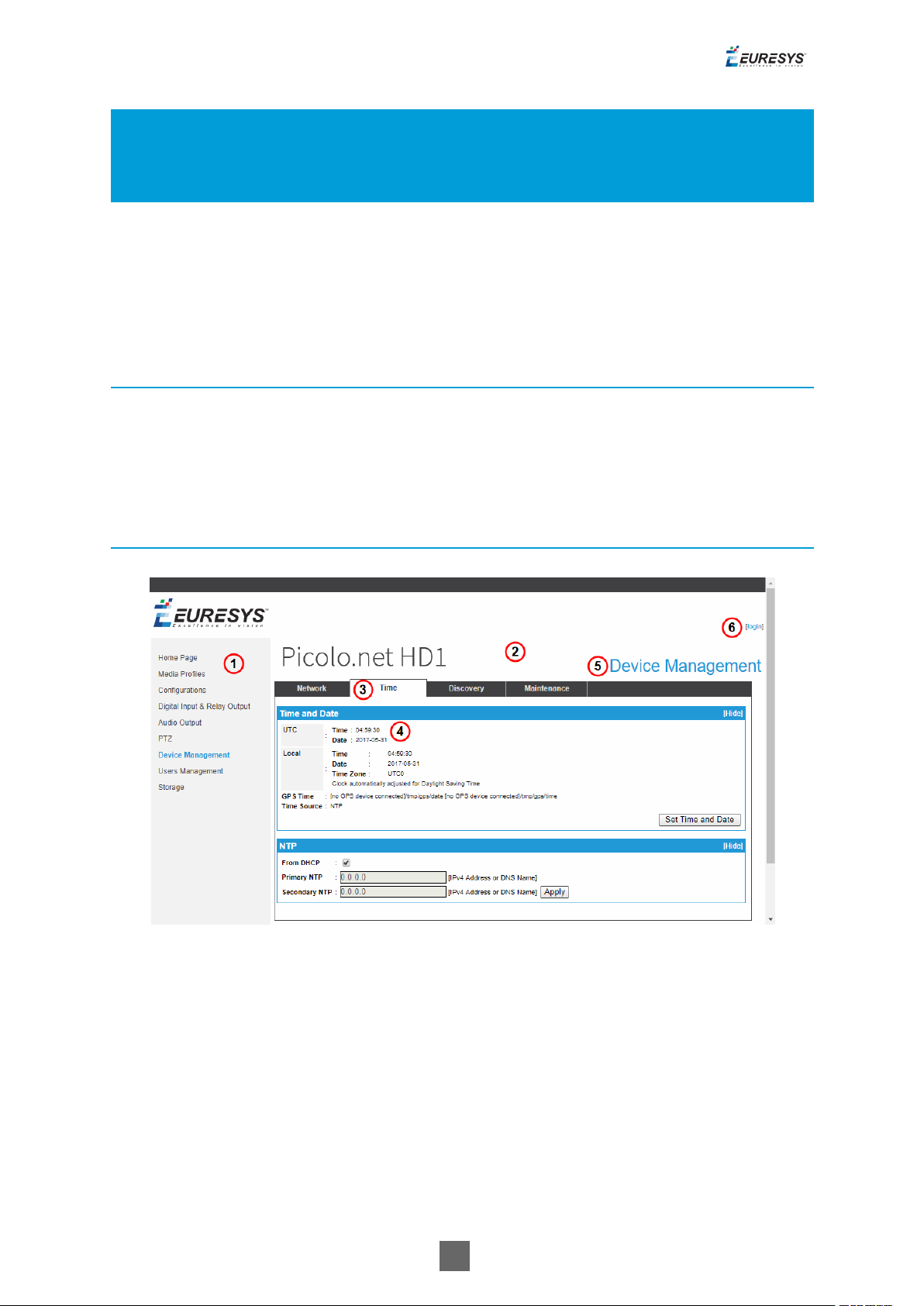
Page Layout
Page sample
1. Left panel: Navigation links
2. Main panel
3. Tab
4. Panel
5. Page title
6. Login
5
Picolo.net User Guide 1. Using the Web Interface
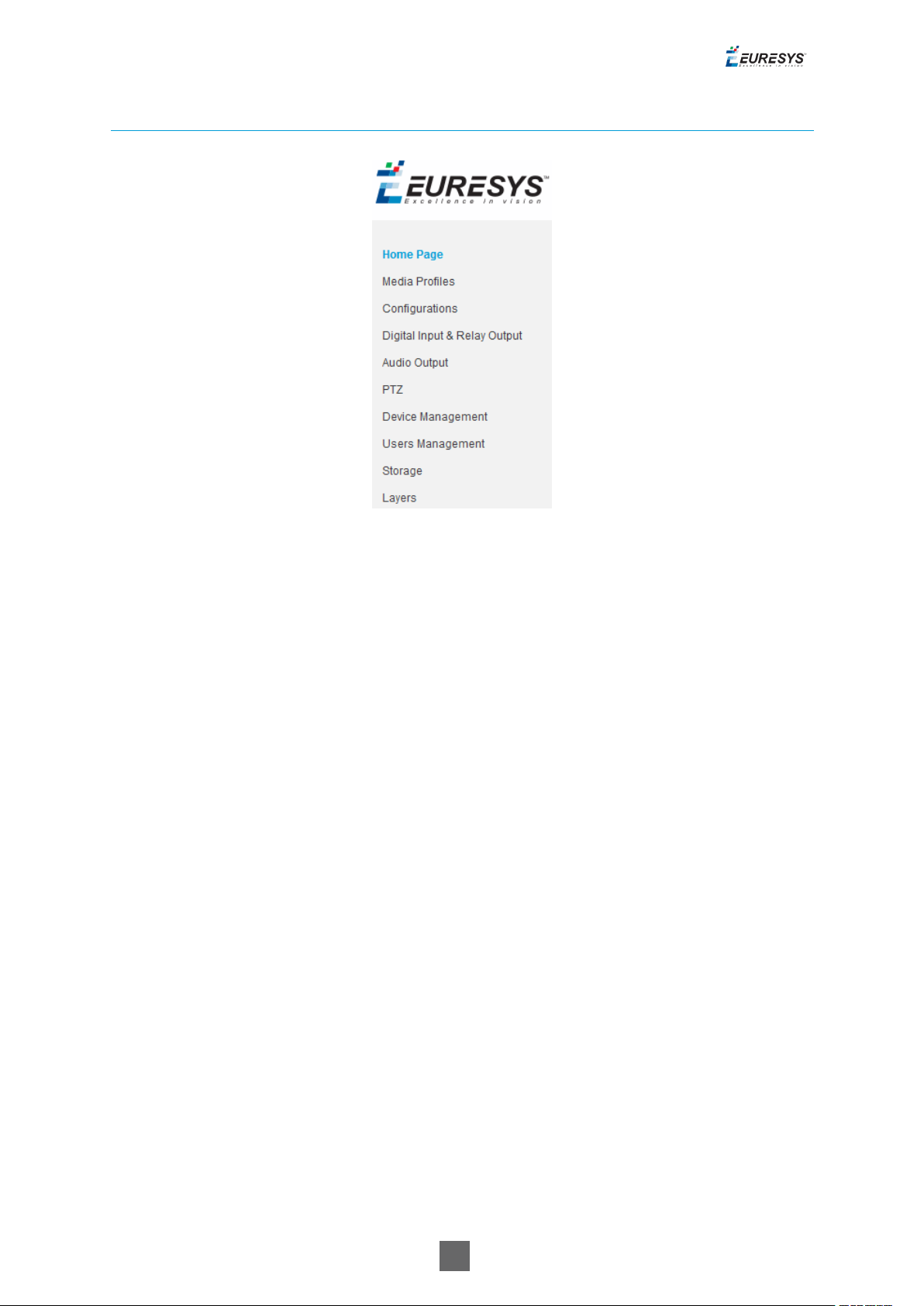
Navigation Links
Navigation Links
Navigation links provide a single-click access to the main page of each section
1. Select "Home Page" on the next page to view device information and display video source.
2. Select "Media Profiles Page" on page11 to view/edit/delete/create media profiles.
3. Select "Configurations Page" on page17 to view/edit configurations of video source, video
encoder, audio source, audio encoder, PTZ and metadata objects.
4. Select "Digital Inputs & Relay Outputs Page" on page33 to view/edit configuration of digital
input and relay output objects.
5. Select "Audio Outputs Page" on page36 to view/edit configuration of audio output object
6. Select "PTZ Page" on page37 to view/edit configuration of the serial port and the PTZNode
objects
7. Select "Device Management Page" on page39 to view/edit network, time and date and
discovery settings and perform maintenance tasks
8. Select "Users Management Page" on page49 to create/delete users and view/edit user
properties.
9. Select "Storage Page" on page50 to mount/unmount storage media,
enable/disable/start/stop recording and list/preview stored media files.
10.Select "Layers Page" on page53 to configure OSD (On Screen Display) location and content.
6
Picolo.net User Guide 1. Using the Web Interface
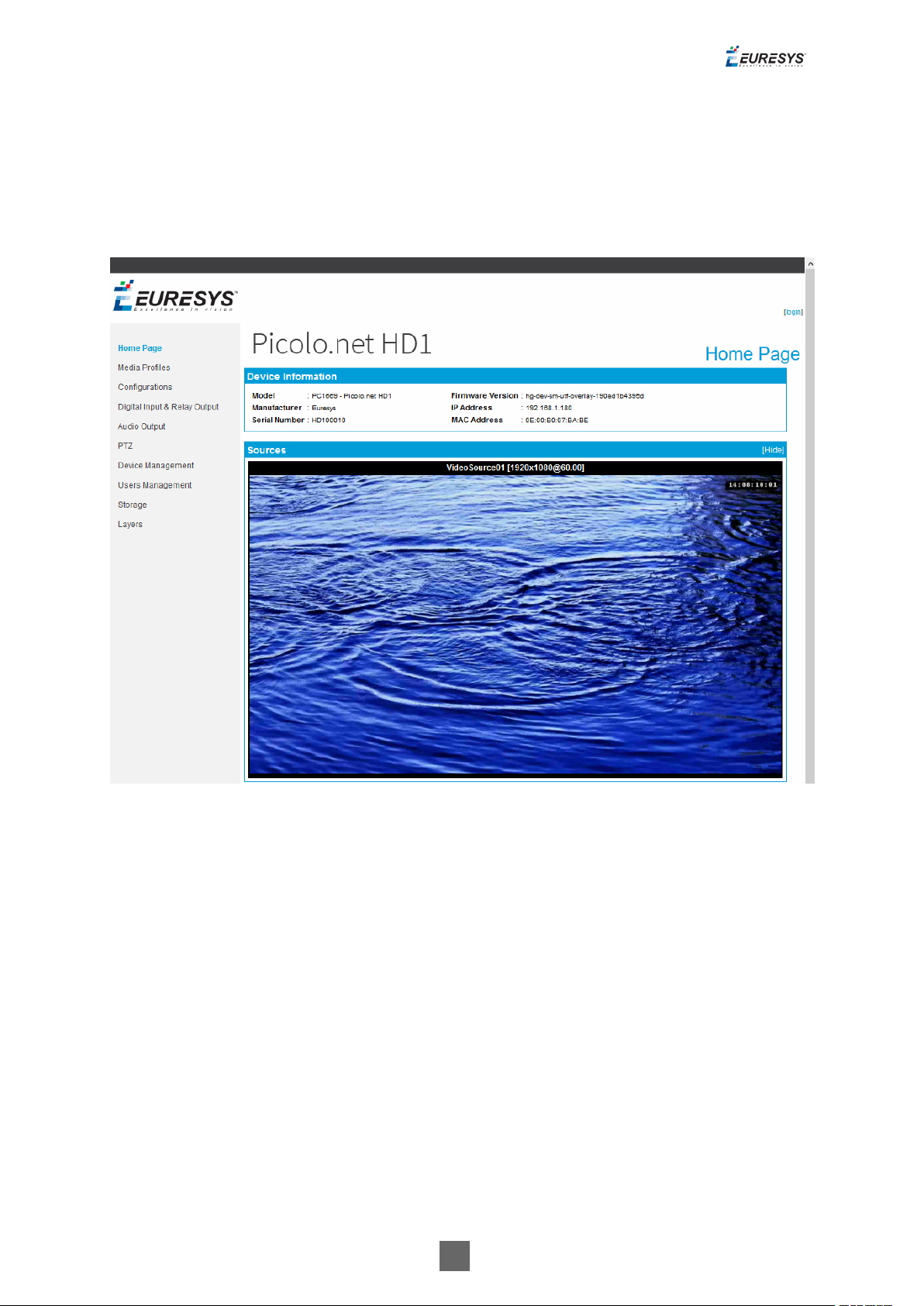
1.2. Home Page
View device information and display video source
Home page
The main pane of the Home page displays 2 panels:
□ A Device Information panel providing general information about the device
□ A Sources panel providing a mosaic display of all the video sources of the device
7
Picolo.net User Guide 1. Using the Web Interface
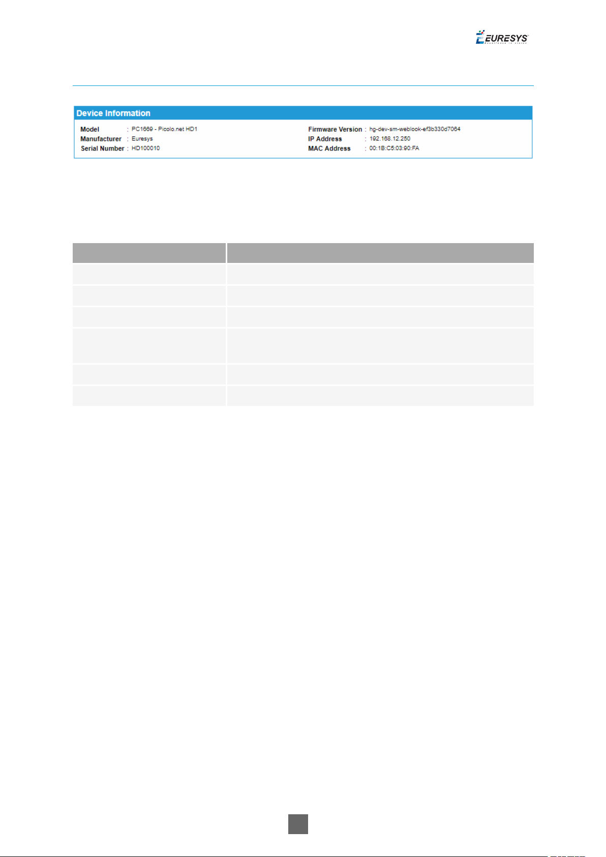
Device Information Panel
Device Information panel
Device Information panel fields description
Name Description
Model Product code and product name of the device
Manufacturer Manufacturer name of the device
Serial Number Serial number of the device
Firmware Version
Major and minor version numbers of the firmware that is
currently on the device.
IP Address IPv4 address of the device currently assigned to the device
MAC Address MAC Address of the LAN port of the device
8

Picolo.net User Guide 1. Using the Web Interface
Sources Panel
Sources panel
The Sources panel shows a rectangular area containing:
□ A title composed of the name, the native resolution, and the native frame rate of the
video source.
□ A snapshot image providing that the source is referenced by a properly configured ONVIF
Media Profile.
Note: If the ONVIF Media Profile is not properly configured, the image is replaced by a black
background overlayed by a crossed rectangle.
If the source has no video, a blue image is displayed.
Clicking on the image brings the browser to the View/Edit Profile page for the profile that
generated the snapshot.
9
Picolo.net User Guide 1. Using the Web Interface
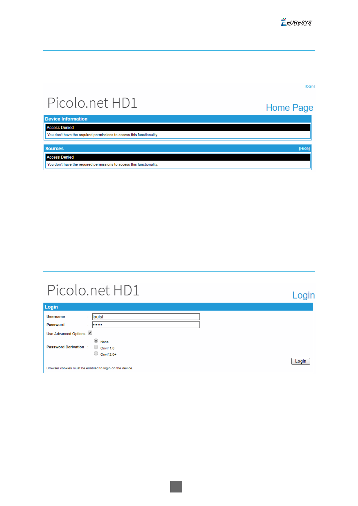
Access Denied Home Page
Once security is enabled, an anonymous user accessing the device Home page obtains the
following page:
Home page when access is denied
Clicking on the [login] hyperlink opens the Login page.
Login Page
The Login page displays the Login panel.
Login panel
Login panel
10
Picolo.net User Guide 1. Using the Web Interface
Login panel fields description
Name Description
Username User name
Password User password
Use Advanced Options Cross the checkbox if specific password derivations are required.
Password Derivation
Password derivation allows the user of multiple devices to type the same string when
authenticating on any device while the value stored on the device is actually different for each
device.
Value Description
None
Onvif
1.0
Onvif
2.0+
No password derivation, the device password is directly typed by the user. Default
setting.
The password is computed (derived) from the device identity and the user-typed
string according to ONVIF 1.0 specification.
The password is computed (derived) from the device identity and the user-typed
string according to ONVIF 2.0 (or later) specification.
1.3. Media Profiles Page
The Media Profiles page displays the Media Profiles panel.
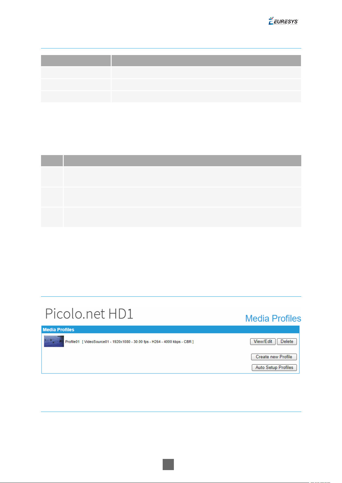
Media Profiles panel
Media Profiles panel
Profiles List
The Media Profiles panel lists all the existing ONVIF Media Profiles.
Each list item contains:
11

Picolo.net User Guide 1. Using the Web Interface
● A thumbnail image of the video source
● The name of the profile e.g. Profile01
● Between square brackets, a selection of profile properties including: name of the video
source, resolution, frame rate, encoding method, bit rate, and rate control method of the
encoded stream.
● A View/Edit button.
● A Delete button.
Clicking on the View/Edit button opens the Media Profile page allowing the user to view or edit
the profile properties.
Clicking on the Delete button deletes the profile.
Profile Creation & Auto Setup
The bottom right area of the Media Profiles panel contains two buttons:
● The Create New Profile button.
● The Auto Setup Profiles button.
Clicking on the Create New Profile button starts the profile creation procedure. First of all, the
procedure opens a dialog box requiring the name of the new profile. Then it displays the
Configurations page allowing the user to configure the ONVIF Media Profile.
Clicking on the Auto Setup Profiles button initiates the auto setup procedure. Before proceeding,
a dialog box opens requiring to confirm the action.
Warning: the auto setup procedure erases all the existing ONVIF Media Profiles!
Media Profile Page
The Media Profile page of the Web Server is relative to a single ONVIF Media Profile. It allows the
user to:
● View the encoded video stream in the Live Media panel
● View the properties of the components of an ONVIF Media Profile using the configuration
panels
● Modify the composition of ONVIF Media Profiles using the Media Profile Configuration panels
The panels composing this page can be hidden or shown individually by clicking on the [Hide]
or [Show] text. Initially, only the Live Media panel is shown.
12

Picolo.net User Guide 1. Using the Web Interface
Live Media Panel
Live Media panel
The Live Media panel provides a live display of the video source unicast stream using the VLC
plug-in of the Web Browser.
The panel title shows, between square brackets, the resolution and the frame rate of the
encoded video stream.
In the bottom area, the panel provides:
● The Unicast URL of the video stream
● The Multicast URL of the video stream
The Start Multicast button starts multicast streaming for the selected media profile.
□ This is not necessary for clients that connect to the stream via the RTSP link provided.
□ Multicast streaming continues until explicitly stopped (even after a reboot of the device).
13
Picolo.net User Guide 1. Using the Web Interface
□ This button also starts RFC2974 session announcement messages for the corresponding
media profile.
The Play Fullscreen button enlarges the live video on the entire screen.
The Use PTZ button adds PTZ controls on the right side of the image as shown on the following
image:
PTZ controls
Media Profile Configuration Panels
Video Source Configuration panel
14
Picolo.net User Guide 1. Using the Web Interface
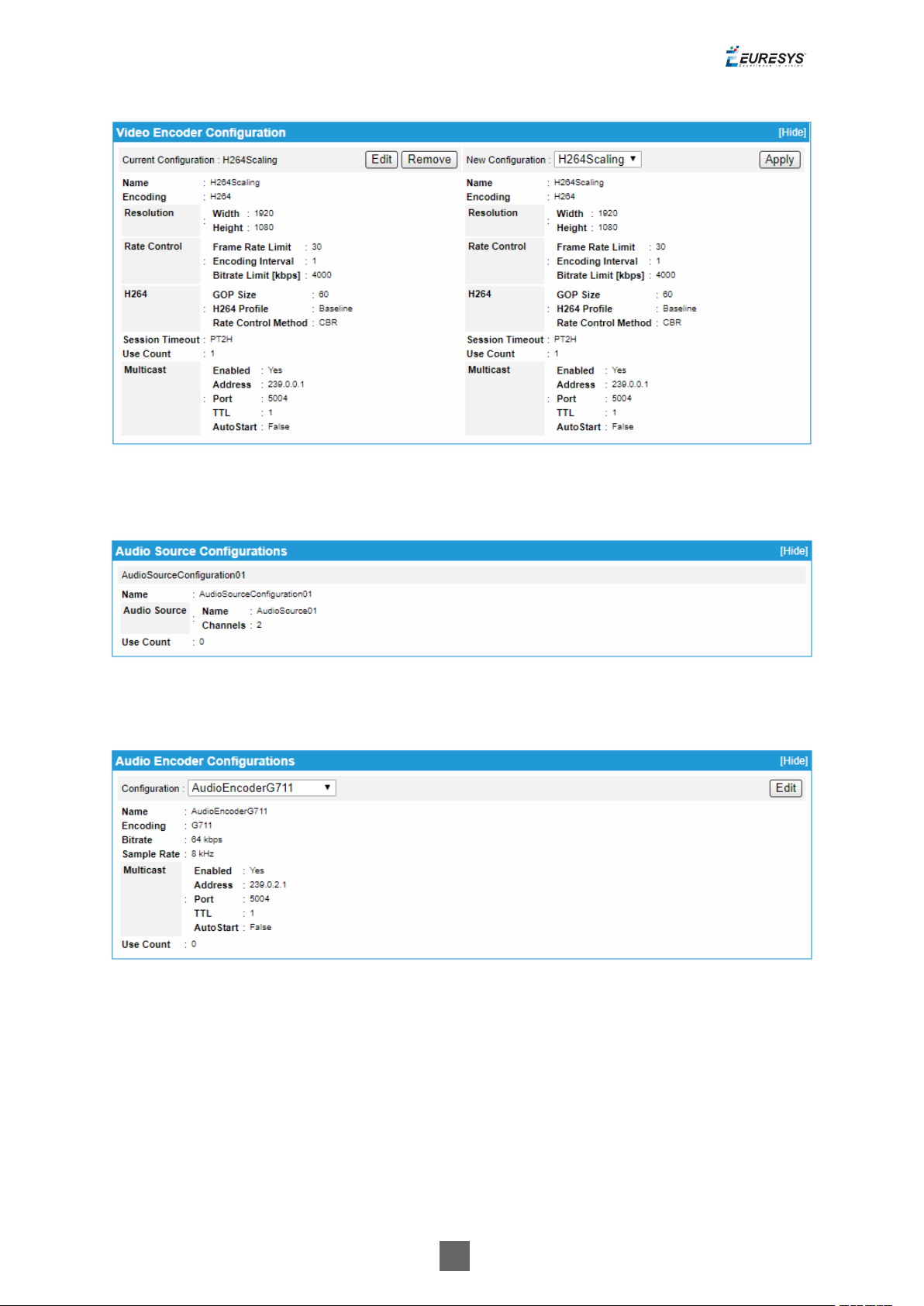
Video Encoder Configuration panel
Audio Source Configurations panel
Audio Encoder Configurations panel
15
Picolo.net User Guide 1. Using the Web Interface
PTZ Configuration panel
Metadata Configuration panel
● The configuration panels of the Media Profile page allow to:
□ View the composition of the profile and the characteristics their components
□ Modify the composition of the profile by addition or deletion of components.
● To facilitate the modification of existing ONVIF Media Profiles, each panel shows
simultaneously for each component:
□ On the left side: the characteristics of the configuration that is currently used by the
ONVIF Media Profile
□ On the right side: the characteristics of any selectable configuration
● Providing that the component is currently used in the profile, the upper left quadrant shows :
□ The name of the current configuration
□ A Remove button
□ An Edit button (only on relevant panels)
● Clicking on the Remove button removes the component from the profile.
● Clicking on the Edit button opens the Edit Configuration panel of the component allowing the
user to edit its properties.
● The upper right quadrant shows:
16

Picolo.net User Guide 1. Using the Web Interface
□ A drop-down box allowing the user to select a new configuration.
□ An Apply button.
● Clicking on the Apply button applies the new configuration to the profile.
1.4. Configurations Page
The Configurations page allows the user to view or edit the configurations of all the software
objects. It provides six panels, one for each component type of an ONVIF Media Profile:
□ "Configurations Page" above
□ "Configurations Page" above
□ "Configurations Page" above
□ "Configurations Page" above
□ "Configurations Page" above
□ "Configurations Page" above
Note: All panels composing this pane can be hidden or shown individually by clicking on the
[Hide] or [Show] text.
17
Picolo.net User Guide 1. Using the Web Interface
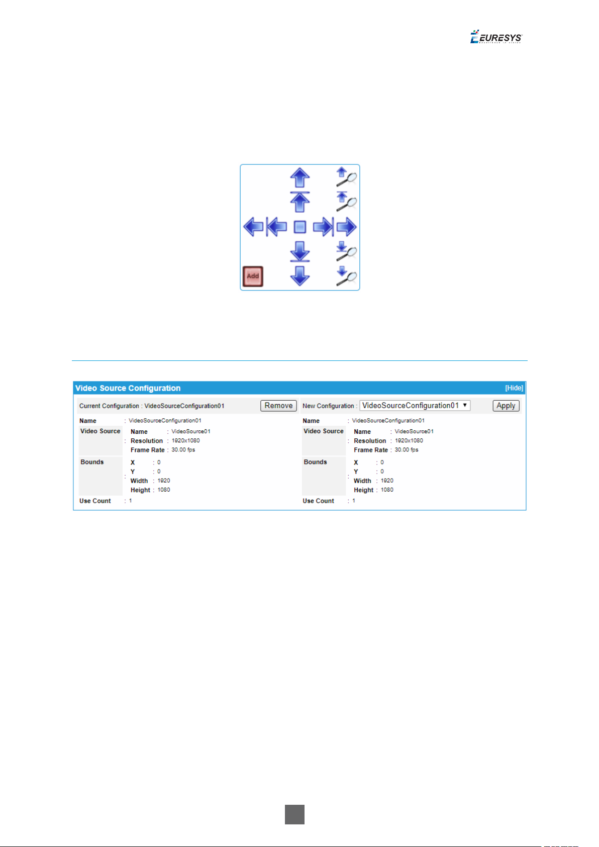
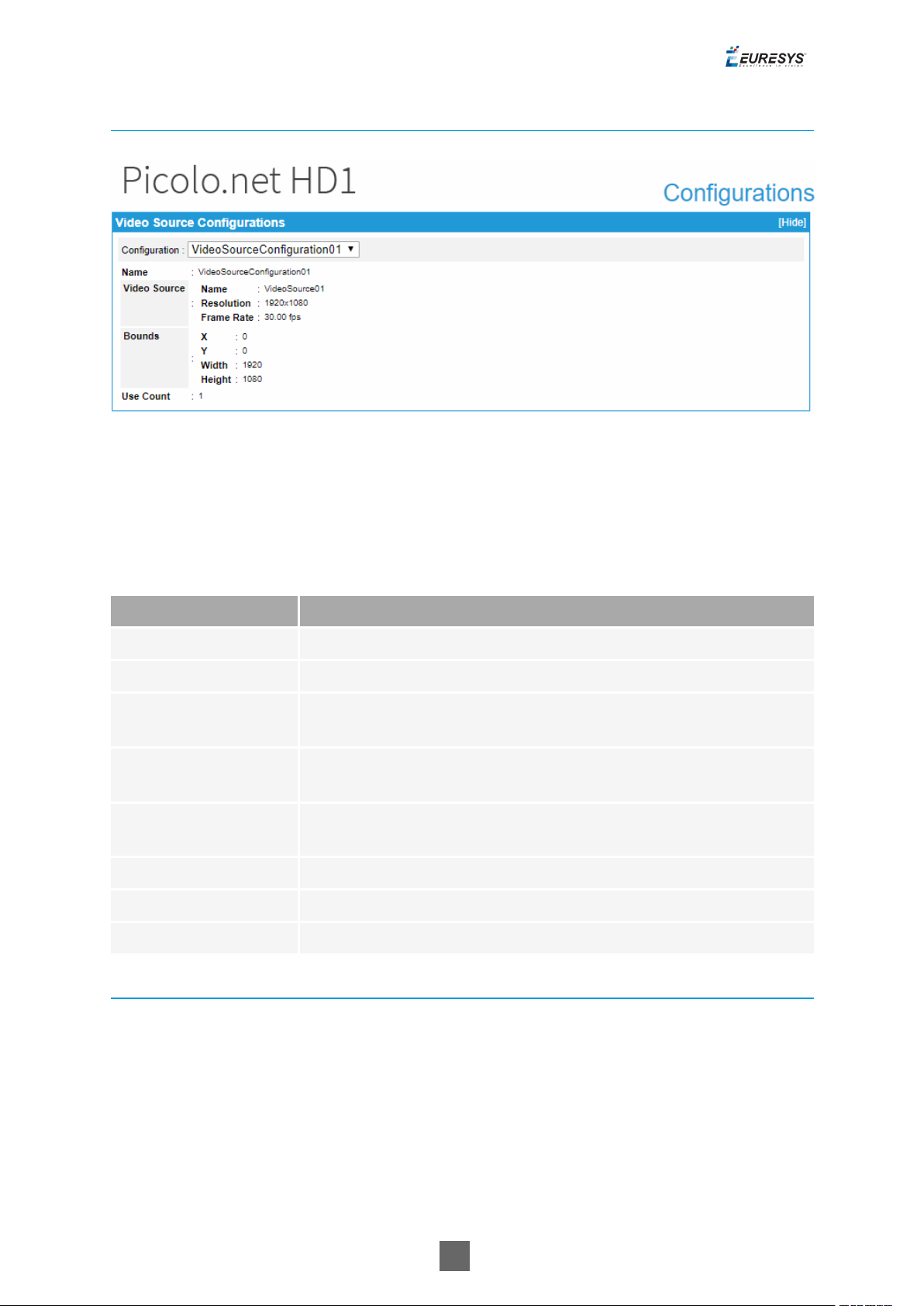
Video Source Configurations panel
Video Source Configurations panel
The drop-down box in the upper area allows to select one VideoSourceConfiguration
object.
Video Source Configurations panel fields description
Name Description
Name The name of the VideoSourceConfiguration object
Video Source - Name The name of the video source
Video Source Resolution
Video Source - Frame
Rate
Bounds - X, Y
The resolution [H x V] of the video source, e.g. 1920x1080
The frame rate of the video source, expressed in fps, e.g.30.00 fps
The position offset of the acquired image relative to the camera
active area
Bounds - Width The number of columns of the acquired image
Bounds - Height The number of lines of the acquired image
Use Count The number of ONVIF Media Profiles using this object
Video Encoder Configurations Panels
The layout of the Video Encoder Configurations panel is specific to the video encoding method:
H.264/ H.265 or JPEG.
18
Picolo.net User Guide 1. Using the Web Interface
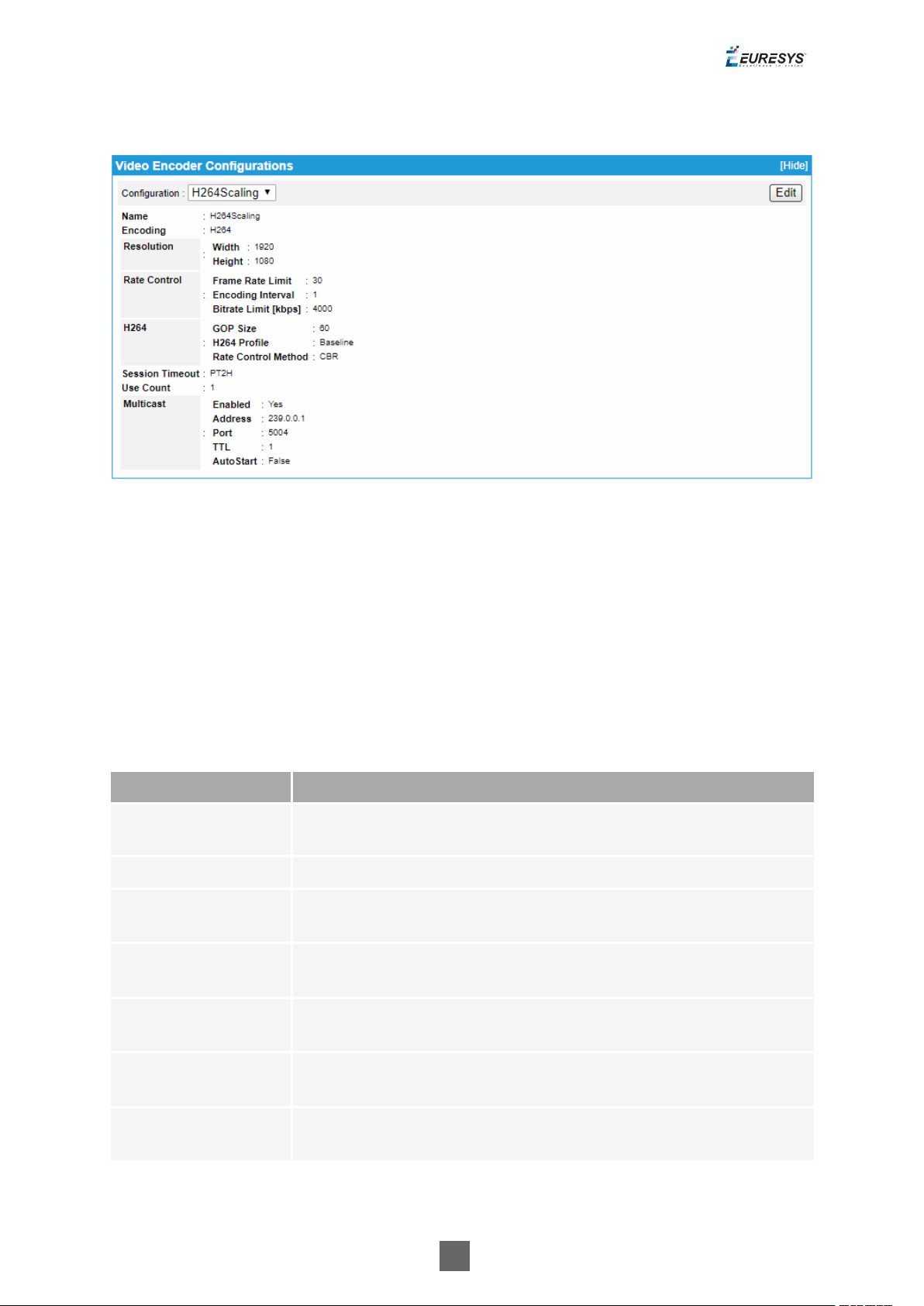
H.264/H.265 Video Encoder Configurations Panel
Video Encoder Configurations panel - H.264/H.265 case
● The drop-down box in the upper area allows to select one VideoEncoderConfiguration
object.
● Clicking the Edit button in the upper area of the panel opens the Video Encoder Configuration
Edition page.
● The lower area of the panel shows the properties of the selected object when it uses the
H.264 or the H.265 encoding method.
Video Source Configurations panel common fields description
Name Description
Name
The token name of the VideoEncoderConfiguration object, e.g.
VideoEncoderConfiguration01
Encoding Used video codec.
Resolution - Width,
Height
Rate Control - Frame
Rate Limit
The image size of the encoded stream
Maximum output frame rate in fps.
Rate Control Encoding Interval
Rate Control - Bitrate
Limit
Session Timeout
Interval at which images are encoded and transmitted.
The maximum output bit rate in kbps
The RTSP session timeout. The duration is expressed using the W3C
lexical representation: PnYn MnDTnH nMnS
19

Picolo.net User Guide 1. Using the Web Interface
Name Description
Use Count
Multicast - Enabled
Multicast - Address
The number of ONVIF Media Profiles using that Video Encoder
Configuration.
Indicates if the RTP multicast streaming of the encoded video is
properly configured with a non-zero IP address and port number.
The IP address of the multicast group. In IPv4, addresses 224.0.0.0
through 239.255.255.255 are designated as multicast addresses.
Multicast - Port The port number of the multicast group.
Multicast - TTL
Multicast - AutoStart
Video Source Configurations panel H.264/H.265 encoder specific fields description
The Time-To-Live of the multicast IP datagrams. Usually 1 since the
datagrams stops after the first router.
Indicates the persistence of multicast streaming. When true, the
multicast streaming starts automatically.
Name Description
H264 - GOP Size Group of Pictures (or Video frames) length.
H264 - H264 Profile The H.264 profile: baseline, main or high.
H.264 - Rate Control Method
The rate control method of the H.264 method:
● VBR: Variable Bit Rate
● CBR: Constant Bit Rate
20
Picolo.net User Guide 1. Using the Web Interface
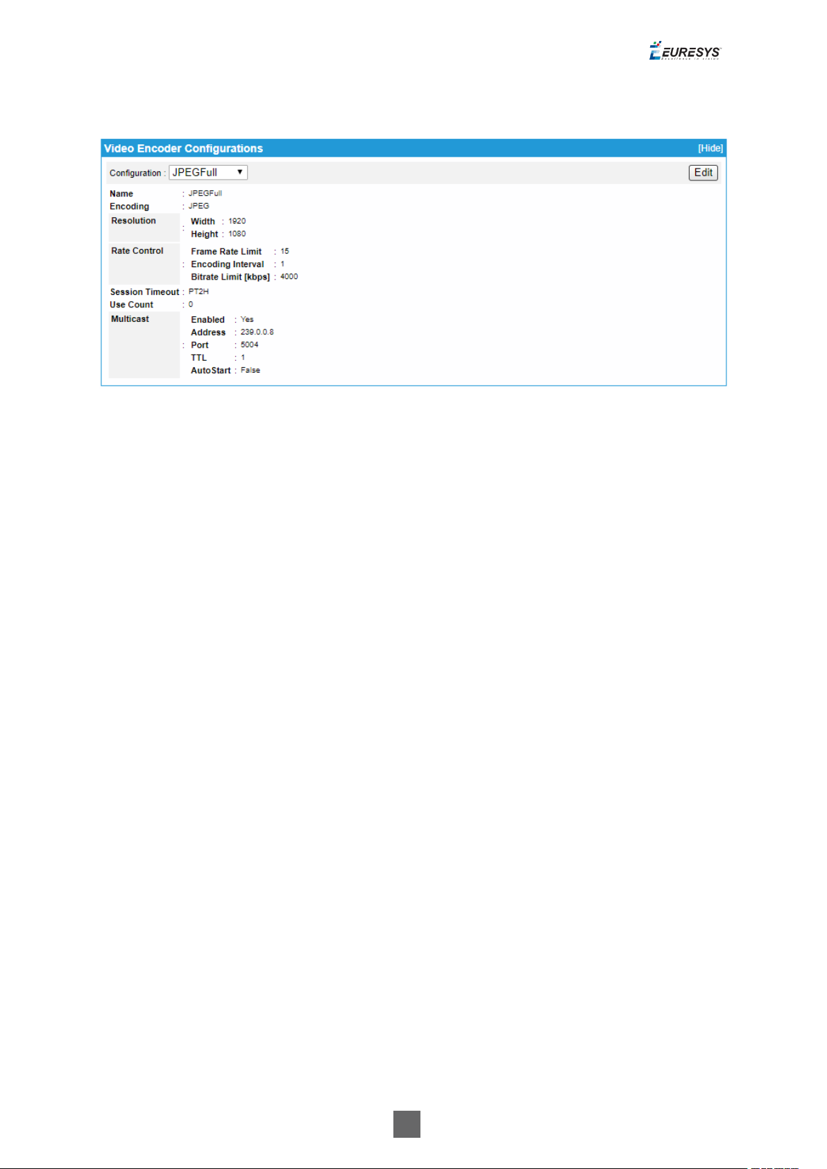
JPEG Video Encoder Configurations Panel
Video Encoder Configurations panel - JPEG case
The drop-down box in the upper area allows to select one VideoEncoderConfiguration
object.
Clicking the Edit button in the upper area of the panel opens the Video Encoder Configuration
Edition page.
The lower area of the panel shows the properties of the selected object when it uses the JPEG
encoding method.
21
Picolo.net User Guide 1. Using the Web Interface
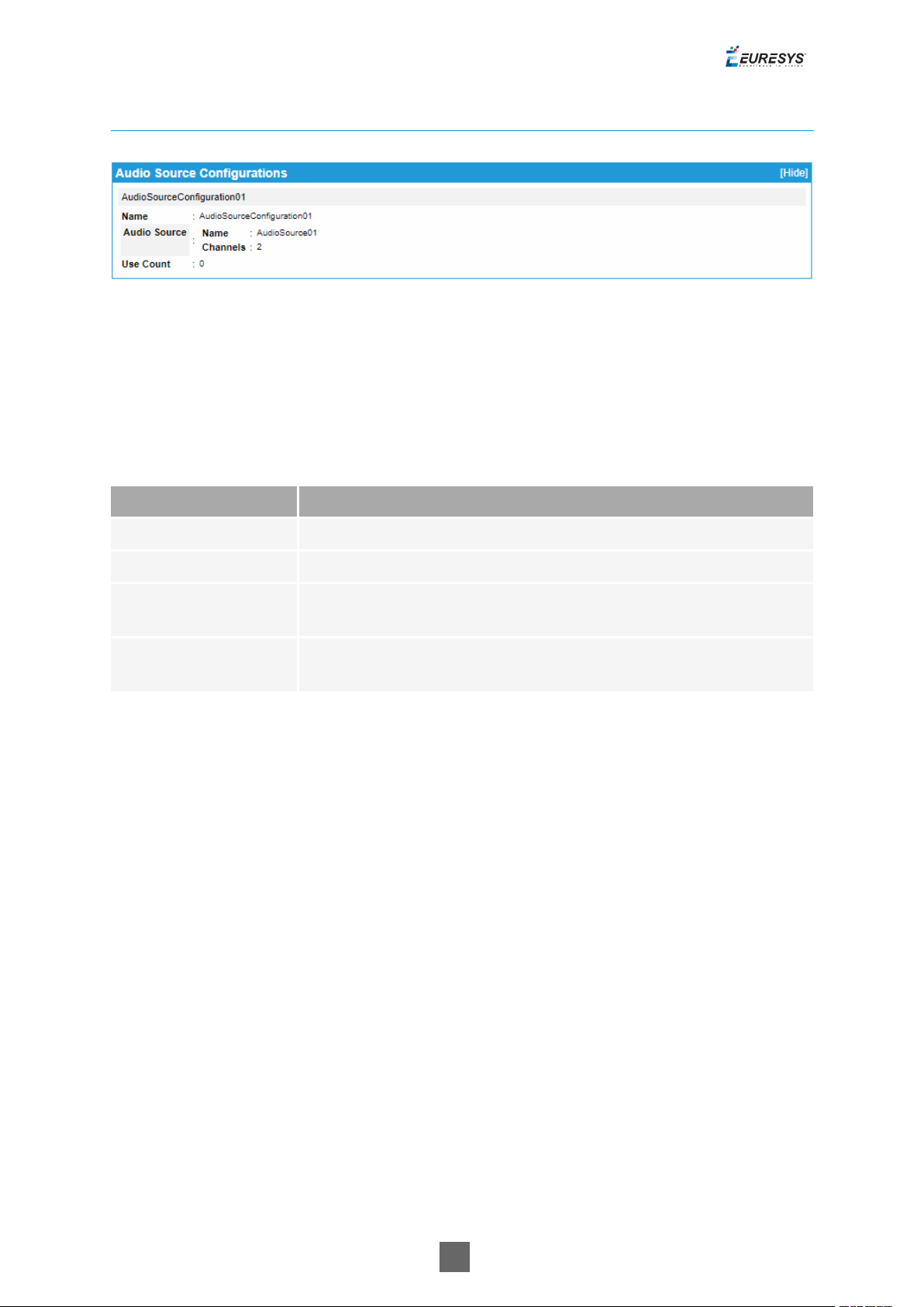
Audio Source Configurations Panel
Audio Source Configurations panel
The drop-down box in the upper area allows to select one AudioSourceConfiguration
object.
The lower area of the panel shows the properties of the selected object:
Audio Source Configurations panel fields description
Name Description
Name The name of the AudioSourceConfiguration object
Audio Source - Name The name of the audio source
Audio Source Channels
Use Count
The number of audio channels of the audio source
The number of ONVIF Media Profiles using that
AudioSourceConfiguration object.
22

Picolo.net User Guide 1. Using the Web Interface
Audio Encoder Configurations panel
Audio Encoder Configurations panel
The drop-down box in the upper area allows to select one AudioEncoderConfiguration
object.
Clicking the Edit button in the upper area of the panel opens the Audio Encoder Configuration
Edition page.
Audio Encoder Configurations panel fields description
Name Description
Name The name of the AudioEncoderConfiguration object
Encoding Used audio codec
Bitrate The bit rate of the encoded audio stream
Sample Rate The sampling rate of the encoded audio stream
Multicast - Enabled
Multicast - Address
Indicates if the RTP multicast streaming of the encoded video is
properly configured with a non-zero IP address and port number.
The IP address of the multicast group. In IPv4, addresses 224.0.0.0
through 239.255.255.255 are designated as multicast addresses.
Multicast - Port The port number of the multicast group.
Multicast - TTL
Multicast - AutoStart
The Time-To-Live of the multicast IP datagrams. Usually 1 since the
datagrams stops after the first router.
Indicates the persistence of multicast streaming. When true, the
multicast streaming starts automatically.
Use Count The number of ONVIF Media Profiles using this object.
23
Picolo.net User Guide 1. Using the Web Interface
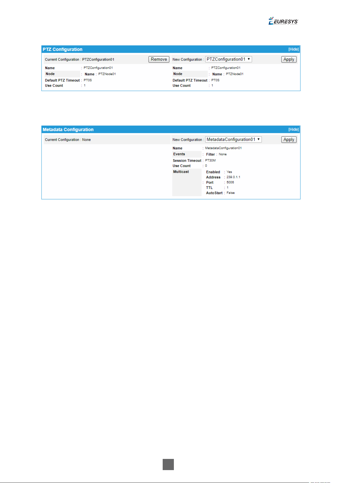
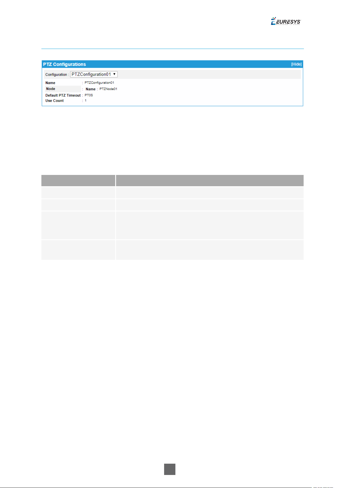
PTZ Configurations Panel
PTZ Configurations panel
The drop-down box in the upper area allows to select one PTZConfiguration object.
The lower area of the panel shows the properties of the selected object:
PTZ Configurations panel fields description
Name Description
Name The name of the PTZConfiguration object
Node - Name The name of the PTZ node, e.g. PTZNode01
The default timeout value for the continuous movements. The
Default PTZ Timeout
duration is expressed using the W3C lexical representation: PnYn
MnDTnH nMnS .
Use Count
The number of ONVIF Media Profiles using that PTZConfiguration
object.
24

Picolo.net User Guide 1. Using the Web Interface
Metadata Configurations Panel
Metadata Configurations panel
The drop-down box in the upper area allows to select one MetadataConfiguration object.
Clicking the Edit button in the upper area of the panel opens the Metadata Configuration Edition
page.
Metadata Configurations panel fields description
Name Description
Name The name of the MetadataConfiguration object
Events - Filter
Session Timeout
List of filtered event items. When empty: means that no events are
filtered.
The RTSP session timeout. The duration is expressed using the W3C
lexical representation: PnYn MnDTnH nMnS
Use Count The number of ONVIF Media Profiles using that object
Multicast - Enabled
Multicast - Address
Indicates if the RTP multicast streaming of the metadata is
properly configured with a non-zero IP address and port number.
The IP address of the multicast group. In IPv4, addresses 224.0.0.0
through 239.255.255.255 are designated as multicast addresses.
Multicast - Port The port number of the multicast group.
Multicast - TTL
Multicast - AutoStart
The Time-To-Live of the multicast IP datagrams. Usually 1 since the
datagrams stops after the first router.
Indicates the persistence of multicast streaming. When true, the
multicast streaming starts automatically.
25

Picolo.net User Guide 1. Using the Web Interface
Edit Video Encoder Configuration Page
The Edit Video Encoder Configuration page allows the edition of the properties of the
VideoEncoderConfiguration object.
It shows a single panel: the Video Encoder Configuration panel.
The layout of the Video Encoder Configurations panel is specific to the video encoding method.
Video Encoder Configuration Panel
H.264/H.265 VIDEO Encoder Configuration Panel
Edit Video Encoder Configuration panel - H.264/H.265 case
26

Picolo.net User Guide 1. Using the Web Interface
JPEG Video Encoder Configuration panel
Edit Video Encoder Configuration panel - JPEG case
Video Encoder Configuration panel common fields description
Name Description
Token
The token name of the VideoEncoderConfiguration object, e.g.
VideoEncoderConfiguration01. This field cannot be edited.
Name A friendly name given to the configuration. Default value = token name
Encoding Video encoding method: H.264 or JPEG
Resolution The resolution of the encoded image, e.g. 1920x1080
Rate
Control Frame
Rate Limit
The maximum output frame rate of the encoded stream, in fps. If an
EncodingInterval is provided, the resulting encoded frame rate will be reduced by
the given factor.
Rate
Control Encoding
The interval at which images are encoded and transmitted. A value of 1 means
that every frame is encoded, a value of 2 means that every 2nd frame is encoded,...
Interval
Rate
Control Bitrate
Limit
Multicast -
The maximum output bit rate in kbps. This field cannot be edited in case of JPEG
encoding.
Check the box to configure RTP multicast streaming.
27

Picolo.net User Guide 1. Using the Web Interface
Name Description
Enable
multicast
Multicast Multicast
Address
The IP address of the multicast group. In IPv4, addresses 224.0.0.0 through
239.255.255.255 are designated as multicast addresses.
Multicast Multicast
The port number of the multicast group.
Port
Multicast Multicast
TTL
Multicast Multicast
AutoStart
Video Encoder Configuration panel H.264/H.265 specific fields description
The Time-To-Live of the multicast IP datagrams. Usually 1 since the datagrams
stops after the first router.
Indicates the persistence of multicast streaming. When true, the multicast
streaming starts automatically. This field cannot be edited.This is enabled/disabled
by clicking on the Start/Stop Multicast button (in the Live Media Panel).
Name Description
Length of the Group of Pictures (or Video frames). Determines typically the interval
GOP
Size
in which the I-Frames will be coded. An entry of 1 indicates I-Frames are continuously
generated. An entry of 2 indicates that every 2nd image is an I-Frame, and 3 only every
3rd frame, etc. The frames in between are coded as P or B Frames.
Profile The H.264 encoder profiles: baseline, main, or high.
Rate
Control
- Rate
Control
Method
Low
Latency
The rate control method of the H.264 encoder. Possible values:
● VBR: Variable Bit Rate
● CBR: Constant Bit Rate
Check the box to configure the low-latency encoding method.
28

Picolo.net User Guide 1. Using the Web Interface
Edit Audio Encoder Configuration Page
The Edit AudioEncoder Configuration page allows the edition of the properties of the
AudioEncoderConfiguration object.
It shows a single panel: the Audio Encoder Configuration panel.
The layout of the Audio Encoder Configurations panel is specific to the audio encoding method.
Audio Encoder Configuration Panel
AAC Audio Encoder Configuration Panel
Edit Audio Encoder Configuration panel - AAC case
G.711 Audio Encoder Configuration Panel
Edit Audio Encoder Configuration panel - G.711 case
29

Picolo.net User Guide 1. Using the Web Interface
LPCM Audio Encoder Configuration Edition panel
Edit Audio Encoder Configuration panel - LPCM case
Audio Encoder Configuration panel fields description
Name Description
Token
The token name of the AudioEncoderConfiguration object, e.g.
AudioEncoderConfiguration01. This field cannot be edited.
Name A friendly name given to the configuration. Default value = token name
Audio encoding method:
● AAC: 1Advanced Audio Coding
Encoding
● G711: G.711 µ-Law
● L16: 16-bit linear PCM
The bitrate of the encoded audio stream expressed in kilobits per second.
● 128 kbps for the AAC encoding method
Bitrate
● 64 kbps for the G.711 encoding method
● 768 kbps for the L16 encoding method
The sampling rate of the encoded audio stream expressed in kHz.
Sample
Rate
Multicast
- Enable
multicast
● Select 48 kHz for the AAC encoding method
● Select 8 kHz for the G.711 encoding method (Default setting)
● Select 48 kHz for the L16 encoding method
Check the button to configure RTP multicast streaming.
30

Picolo.net User Guide 1. Using the Web Interface
Name Description
Multicast
Multicast
Address
Multicast
Multicast
Port
Multicast
Multicast
TTL
The IP address of the multicast group. In IPv4, addresses 224.0.0.0 through
239.255.255.255 are designated as multicast addresses.
The port number of the multicast group.
The Time-To-Live of the multicast IP datagrams. Usually 1 since the datagrams
stops after the first router.
Multicast
Multicast
AutoStart
Indicates the persistence of multicast streaming. When true, the multicast
streaming starts automatically. This field cannot be edited.This is enabled/disabled
by clicking on the Start/Stop Multicast button (in the Live Media Panel).
Edit Metadata Configuration Page
The Edit Metadata Configuration page allows the edition of the properties of the
MetadataConfiguration object.
It shows a single panel: the Metadata Configuration panel.
31

Picolo.net User Guide 1. Using the Web Interface
Metadata Configuration Edition panel
Edit Metadata Configuration panel
Metadata Configuration panel fields description
Name Description
Token
Name
Events - Filter
Session Timeout
Multicast - Enable
multicast
Multicast - Multicast
Address
The token name of the MetadataConfiguration object, e.g.
MetdataConfiguration01. This field cannot be edited.
A friendly name given to the configuration. Default value = token
name
List of filtered event items. When empty: means that no events are
filtered.
The RTSP session timeout. The duration is expressed using the W3C
lexical representation: PnYn MnDTnH nMnS
Check the button to configure RTP multicast streaming.
The IP address of the multicast group. In IPv4, addresses 224.0.0.0
through 239.255.255.255 are designated as multicast addresses.
Multicast - Multicast
Port
Multicast - Multicast
TTL
Multicast - Multicast
AutoStart
The port number of the multicast group.
The Time-To-Live of the multicast IP datagrams. Usually 1 since the
datagrams stops after the first router.
Indicates the persistence of multicast streaming. When true, the
multicast streaming starts automatically. This field cannot be edited.
32

Picolo.net User Guide 1. Using the Web Interface
1.5. Digital Inputs & Relay Outputs Page
The Digital Inputs & Relay Outputs page allows the user to view or edit the configuration of
DigitalInput and RelayOutput objects.
A DigitalInput object represents an Alarm Input port; a RelayOutput object represents one
Relay Output port.
Note: The panels composing this pane can be hidden or shown individually by clicking on the
[Hide] or [Show] text.
Digital Input Panel
Digital Input panel
The Digital Input panel allows the user to view the configuration of DigitalInput objects.
The drop-down box in the upper area allows to select one DigitalInput object.
Digital Input panel fields description
Name Description
Type (amplitude) of signal. Possible values are:
● TTL => threshold voltage = 1.5 V
Voltage Threshold
● 5VCMOS => threshold voltage = 2.5 V
● 12V => threshold voltage = 6V
The strength (time constant) of the deglitching filter. Possible
values are:
● OFF => No filtering
Timing Filter
● 10ms => Weak filtering: filters out transients shorter than 10
milliseconds
● 100ms =>Strongest filtering: filters out transients shorter than
100 milliseconds
33

Picolo.net User Guide 1. Using the Web Interface
Name Description
Events Enabled
When true, any valid (= not filtered out) transition on the input
produces an event.
Clicking on the Edit button opens the Edit Digital Input Configuration page.
Clicking on the Show Input States button opens the Digital Input States page.
EDIT Digital Input Configuration Page
Edit Digital Input panel
The Edit Digital Input Configuration page displays a single panel, named Digital Input, allowing
the user to edit the properties of the selected Digital Input object.
Checking the Enable Events check box enables the event generation for that input.
Digital Inputs States page
The Digital Inputs States page displays a single panel allowing the user to view the state of all
DigitalInput objects.
Digital Input States panel
The Digital Inputs States panel is refreshed automatically.
State values for contact closure devices
State Description
OPEN The contact is open
LOW The contact is closed
34

Picolo.net User Guide 1. Using the Web Interface
State values for logical devices
State Description
OPEN Logical device is in High-Z
LOW Logical device is driving LOW
HIGH Logical device is driving HIGH
Relay Output Panel
Relay Output panel
The Relay Output panel allows the user to view the configuration of RelayOutput objects.
The drop-down box in the upper area allows to select one RelayOutputobject.
The lower area of the panel shows the properties of the selected object:
Relay Outputs panel fields description
Name Description
The operating mode of the relay output. Possible values are:
Properties
- Mode
● Monostable => After setting the state, the relay returns to its idle state after
the specified time.
● Bistable => After setting the state, the relay remains in this state.
Properties
- Delay
Time
Specifies the time after which the relay returns to its idle state if it is in
monostable mode. If the relay is set to bistable mode the value of the parameter
shall be ignored. The duration is expressed using the W3C lexical representation:
PnYn MnDTnH nMnS
Position of the relay when the relay state is set to ‘inactive’ through the trigger
Properties
- Idle
State
command.. Possible values are:
● Closed => The relay is closed.
● Open=> The relay is open
Clicking on the Edit button opens the Edit Relay Output Configuration page.
35

Picolo.net User Guide 1. Using the Web Interface
Edit Relay Output Configuration Page
Edit Relay Output panel
The Edit Relay Output Configuration page displays a single panel, named Relay Output, allowing
the user to edit the properties of the selected RelayOutput object.
1.6. Audio Outputs Page
The Audio Outputs page allows the user to view or edit the configuration of Picolo
AudioOutput objects.
A Picolo AudioOutput object represents one Audio Output port.
Picolo Audio Output Panel
Picolo Audio Output Panel
The Picolo Audio Outputs panel allows the user to view the configuration of Picolo
AudioOutput objects.
The drop-down box in the upper area allows to select one Picolo AudioOutput object.
The lower area of the panel shows the properties of the selected object:
Picolo Audio Output panel fields description
Name Description
Source URI URI of an RTSP audio stream
Username User name on the RTSP server
36

Picolo.net User Guide 1. Using the Web Interface
Clicking on the Edit button opens the Edit Picolo Audio Output Configuration page.
Edit Picolo Audio Output Configuration page
The Edit Picolo Audio Output Configuration page displays a single panel allowing the user to edit
the properties of a Picolo AudioOutput object.
1.7. PTZ Page
The PTZ page allows the user to view or edit the configuration of the serial port and the
PTZNode objects.
Serial Port Configuration panel
Serial Port Configuration panel
The Serial Port Configuration panel allows the user to view the properties of the serial port.
Serial Port Configuration panel fields description
Name Description
Baud Rate The baud rate of the serial port
Character Length Number of bits per character
Parity Bit Presence and polarity of the parity bit
Stop Bit Number of stop bits
37

Picolo.net User Guide 1. Using the Web Interface
Clicking on the Edit button opens the Edit Serial Port Configuration page.
Edit Serial Port Configuration Page
Edit Serial Port Configuration panel
The Edit Serial Port Configuration page displays a single panel, named Serial Port Configuration,
allowing the user to edit the properties of the serial port.
Clicking on the Save Changes button in the lower right area saves the settings.
PTZNode panel
PTZNode panel
The PTZNode panel allows the user to view the properties of the corresponding PTZNode:
PTZNode panel fields description
Name Description
Maximum Number of
Presets
Indicates the maximum number of presets supported by the
PTZ protocol. 20 for Pelco-D protocol.
Home Supported
Indicates if the home command is supported by the PTZ
protocol. True for Pelco-D protocol.
Serial Address The address given to the PTZ node
Clicking on the Change button assigns the serial address to the PTZ node.
Clicking on the Use PTZ button adds PTZ controls for this PTZ node.
38

Picolo.net User Guide 1. Using the Web Interface
Live Stream panel with PTZ controls
The Add button in the PTZ controls allows the user to recording the current PTZ position as a
preset in the camera.
Note: A third-party software is still required to update or delete such presets.
1.8. Device Management Page
Network Tab 40
Time Tab 43
Discovery Tab 46
Maintenance Tab 47
39

Picolo.net User Guide 1. Using the Web Interface
Network Tab
The Network tab of the Device Management page allows the user to view or edit all the network
related settings.
Network tab
Device Host Name Panel
● The Device Hostname panel allows the user to view and/or edit the device host name.
● Clicking on the Apply button registers the change. It will be effective after a device reboot.
40

Picolo.net User Guide 1. Using the Web Interface
IP Address Panel
● The IP Address panel allows the user to view and/or edit the device IP address and the sub-
net mask.
● When the From DHCP check box is checked, the IP address is obtained automatically using
DHCP. The IP and Subnet Mask fields reflect the values assigned automatically by the DHCP
server. These values cannot be modified.
● When the From DHCP check box is unchecked, the user is allowed to change the IP and
Subnet Mask fields.
● Clicking on the Apply button registers the change. It will be effective after a device reboot.
DNS Panel
● The DNS panel allows the user to view and/or edit the IP address of the primary and
secondary DNS servers.
● When the From DHCP check box is checked, the IP addresses of the primary and secondary
DNSservers are obtained automatically using DHCP. The Primary DNS and Secondary DNS
fields reflect the values assigned automatically by the DHCP server. These values cannot be
modified.
● When the From DHCP check box is unchecked, the user is allowed to change the Primary DNS
and Secondary DNS fields.
● Clicking on the Apply button registers the change. It will be effective after a device reboot.
Default Gateways Panel
● The Default Gateways panel allows the user to view the IP address of the default gateways.
When the IP address of the device is statically assigned, default gateways can be added,
edited, or deleted.
Protocols Panel
● The Protocols panel allows the user to Individually enable/disable the HTTP, HTTPS, and
RTSP protocols and assign a port number to each.
41

Picolo.net User Guide 1. Using the Web Interface
IP Change Panel
● After a change of the IP Adress settings, the IPChange panel is displayed. It indicates that the
IPaddress change will be effective only after rebooting the device.
● Clicking on the OK button returns to the last page. The Must reboot banner appears on top of
it:
Must reboot banner
42

Picolo.net User Guide 1. Using the Web Interface
Time Tab
The Time tab of the Device Management page allows the user to view or edit all the time and
date related settings.
Time tab
Time and Date Panel
Name Description
UTC - Time The UTC (Coordinate Universal Time) time value.
UTC - Date The UTC (Coordinate Universal Time) date value.
Local - Time The local time value.
Local - Date The local date value. Expressed in YYYY-MM-DD format.
Local - Time Zone The local time zone rule. Expressed in POSIX.1 TZ string format.
GPS Time The UTC time provided by the GPS receiver device.
Time Source The source used for time and date synchronization.
● The Time and Date panel allows the user to view the time and date settings.
● The Time fields use the HH:MM:SS format. The Date fields use the YYYY-MM-DD format. The
Time Zone field use the POSIX.1 TZ string format.
43

Picolo.net User Guide 1. Using the Web Interface
● A Clock automatically adjusted for Daylight Saving Time message indicates that the DST rule
of the POSIX.1 TZ string is effectively considered by the Operating Systems.
● A Clock not automatically adjusted for Daylight Saving Time. message indicates that the DST
rule of the POSIX.1 TZ string is ignored by the Operating Systems.
● Clicking on the Set Time and Date button opens the Edit Date and Time page.
● When the automatic GPS with NTP method is used, Time Source reports either GPS or NTP
depending on whether a GPS device is actively providing time information.
Date and Time Panel
● The Date and Time panel of the Edit Date and Time page allows the user to modify all the time
and date settings.
● The Time Source drop-down box allows to select the source of the time synchronization.
□ NTP selects the automatic synchronization method using NTP protocol.
□ NTP + GPS enables USB GPS device to act as an NTP time source.
□ Manual selects the manual synchronization method.
Note: When manual synchronization method is selected, all the six fields of UTC Time area must
be properly filled with the actual values of the UTC time.
● The drop-down box in the Time Zone area provides a list of time zone sorted by increasing
UTC offset values. Selecting an item automatically fills the edit box with the corresponding
POSIX.1 TZ string.
Note: The validity of the TZ rules is not guaranteed. Indeed, TZ rules are subject to modification
by civil authorities.
● The edit-box in the Time Zone area specifies the time zone rule expressed in POSIX.1 TZ string
format. An empty field means that the local time is equal to the UTC time.
● The Automatically adjust clock for Daylight Saving Time check box controls the application of
the DST (Daylight Savings Time) rule embedded in the time zone string. When checked, the
device updates automatically the local time according to the DST rule. When unchecked, the
device ignores the DST rule.
● Clicking on the Apply button immediately applies the settings.
44

Picolo.net User Guide 1. Using the Web Interface
NTP Panel
● The NTP panel allows the user to view and/or edit the IP address of the primary and
secondary NTP servers.
● When the From DHCP check box is checked, the IP addresses of the primary and secondary
NTPservers are obtained automatically using DHCP. The Primary NTP and Secondary NTP
fields reflect the values assigned automatically by the DHCP server. These values cannot be
modified.
● When the From DHCP check box is unchecked, the user is allowed to change the Primary NTP
and Secondary NTP fields.
● Clicking on the Apply button registers the change.
45

Picolo.net User Guide 1. Using the Web Interface
Discovery Tab
The Discovery tab of the Device Management page allows the user to view or edit all the device
discovery settings.
Discovery tab
Discovery Panel
● The Device is discoverable check box controls the ability to discover the device on the
network using the discovery functions of the ONVIF Device Web Service. When checked, the
device is discoverable. When unchecked, the device don't reply to the discovery request
messages.
● Clicking on the Apply button applies immediately the settings.
Scopes Panel
● The Scopes panel allows the user to view and create ONVIF device scopes.
● Clicking on the Add Scope button opens a dialog box allowing to create a new scope.
● For user editable scopes, the panel provides an Edit button and a Delete button. Clicking on
an Edit button opens a dialog box allowing to modify the scope. Clicking on a Delete button
opens a dialog box allowing to delete the scope.
46

Picolo.net User Guide 1. Using the Web Interface
Maintenance Tab
The Maintenance tab of the Device Management page allows the user to perform maintenance
tasks.
Maintenance tab
Device Information Panel
Name Description
Model Product code and product name of the device
Manufacturer Manufacturer name of the device
Serial Number Serial number of the device
Firmware Version Major and minor firmware version numbers of the device
GPS Location GPS coordinates of the actual device location
IP Address IPv4 address of the device currently assigned to the device
MAC Address MAC Address of the LAN port of the device
47

Picolo.net User Guide 1. Using the Web Interface
Name Description
Hostname Host name currently assigned to the device
Internal Temperature Internal temperature of the device, expressed in °C
USB Storage
Indication of presence and capacity of an USB 2.0
compatible mass storage device (if any).
A [no GPS device connected] message indicates that there are no active GPS device attached to a
USB port.
A no device message indicates that there are no storage device attached to a USB port.
Get Device Logs Panel
● The Get Device Logs panel allows the user to retrieve log files from the device.
● Clicking on the Get Systems Logs button initiates the download of the system.logs.tar.gz
file containing the system logs data.
● Clicking on the Get Access Logs button initiates the download of the access.logs.tar.gz
file containing the access logs data.
Note: In the log files, time is expressed in UTC time.
Reboot Device Panel
● The Reboot Device panel allows the user to reboot the device.
● Clicking on the Reboot Now button opens a dialog box allowing to initiate or cancel the task.
Revert Device to Factory Settings Panel
● The Revert Device to Factory Settings panel allows the user to revert the device settings to
their initial value at factory output.
● Clicking on the Revert Now button opens a dialog box allowing to initiate or cancel the task.
● The Reset network parameters check box controls the reverting of the network settings and
the user database. When checked, the network related settings and the user database are
also reverted. When unchecked, the network related settings and the user database are not
reverted.
Firmware Upload Panel
● The Firmware Upload panel allows the user to upload a firmware to the device.
● Clicking on the Browse button opens the file browser for example Windows Explorer allowing
to select the firmware image file to upload.
● Clicking on the Upload Firmware opens a dialog box allowing to initiate or cancel the task.
48

Picolo.net User Guide 1. Using the Web Interface
1.9. Users Management Page
The Users Management page allows a user (with sufficient rights ) to create and delete users and
to view or edit user properties.
Users panel
● The Users panel of the Users Management page displays the list of users.
● Each list item contains the user name and the user level between square brackets, an Edit
and a Delete button.
● Clicking the Delete button deletes the user.
● Clicking the Edit button or the Create New User button opens the User Edition page.
49

Picolo.net User Guide 1. Using the Web Interface
User panel on the User Edition page
User panel
User panel fields description
Name Description
Username User name
Password User password
Confirm password User password again
Access Level User access level. Possible values: Administrator, Operator, User
Password Derivation Enable, disable and configure ONVIF password derivation.
Password Derivation
Password derivation allows the user of multiple devices to type the same string when
authenticating on any device while the value stored on the device is actually different for each
device.
Value Description
None
Onvif
1.0
No password derivation, the device password is directly typed by the user. Default
setting.
The password is computed (derived) from the device identity and the user-typed
string according to ONVIF 1.0 specification.
Onvif
2.0+
The password is computed (derived) from the device identity and the user-typed
string according to ONVIF 2.0 (or later) specification.
1.10. Storage Page
The Storage page allows the user to mount/unmount USB storage media,
50

Picolo.net User Guide 1. Using the Web Interface
enable/disable/start/stop recording and list/preview stored media files.
The Storage page displays three panels:
□ Media Control
□ Recording Control
□ Stored Media
Media Control Panel
Media Control panel
The Media Control panel allows to control the USB media.
● 1669 Picolo.net HD1 automatically detects USB mass storage devices as they are plugged in.
□ Devices with a FAT32, exFAT and EXT4 file system are automatically mounted when
plugged in.
□ If the device is not listed, press [Refresh] on the media control panel to update the page.
□ Click on the mount USBmedia button.
● When mounted, the status field turns reports a ready condition together with the remaining
and the total capacity of the USB media.
● If 1669 Picolo.net HD1 does not recognize the file system format or if the root / partition
information is corrupted on the device:
□ It reports a "bad disk" status.
□ It offers to format the first (or only) partition of the device in EXT4.
You can safely unplug a device with the "bad disk" status.
● To unmount a USBmedia:
□ Click on the unmount USBmedia button.
□ The recording job stops and all pending data are written.
□ The status turns to 'idle safe for removal' to confirm the operation.
□ Remove the device or manually mount the partition again.
51

Picolo.net User Guide 1. Using the Web Interface
Recording Control Panel
Recording Control panel
The Recording Control panel allows the user to control the recording .
● To enable recording:
□ Ensure that the USBmedia is correctly mounted.
□ Ensure that the selected media profile exists and uses codecs compatible with MP4 file
format (H.264 and AAC only).
□ Adjust the minimum file size if required (a new file is created every time a new group-of-
picture starts and the file is greater than this value).
□ Configure the amount of storage the 1669 Picolo.net HD1 is allowed on the device if
circular recording is used or use 'unlimited' in the 'circular storage size'.
□ Click on the enable button. This automatically starts the recording if a disk is connected.
● To disable recording:
□ Click on the disable button.
The recording enable/disable settings is persistent. It is not affected by device reboot or by a power
on/off/on cycle.
● To start recording:
□ The recording automatically starts when you enable the recording job.
● To stop recording:
□ Click on the stop button.
● To resume recording:
□ Ensure that the USBmedia is correctly mounted and the recording is enabled.
□ Click on the start button.
52

Picolo.net User Guide 1. Using the Web Interface
Stored Media Panel
Stored Media panel
The Stored Media panel lists the files recorded by the Picolo.net encoder on the USBmedia.
To download a file, click on the file name.
1.11. Layers Page
The Layers page allows the user to configure and position the OSD (On Screen Display) content.
The Storage page displays three panels:
□ TimeOSDConfiguration
□ UserOSDConfiguration (you can use any Chinese, Cyrillic, Greek, Japanese, Korean and
Latin characters).
□ AutoOSDConfiguration
Note:
- UserOSDConfiguration and AutoOSDConfiguration are not rendered on the HDMI output, but
only on the encoded bitstreams.
- TimeOSDConfiguration is rendered on both encoded bitstreams and HDMI output.
TimeOSDConfiguration Panel
TimeOSDConfiguration panel
53

Picolo.net User Guide 1. Using the Web Interface
The TimeOSDConfiguration panel controls a hardware time stamp incremented at every frame.
Use the following controls to define the text display:
□ Select the Position of the text.
□ Set the Size (pt) of the font used.
□ Click on the setup button to apply the changes if the layer is shown.
□ Click on the hide / show button to enable or disable the text display.
UserOSDConfiguration Panel
UserOSDConfiguration panel
The UserOSDConfiguration panel controls a hardware time stamp incremented at every frame.
Use the following controls to define the text display:
□ Select the Position of the text.
□ Set the Size (pt) of the font used.
□ Enter the Text you want to display on the screen.
□ Click on the setup button to apply the changes if the layer is shown.
□ Click on the hide / show button to enable or disable the text display.
AutoOSDConfiguration Panel
AutoOSDConfiguration panel
54

Picolo.net User Guide 1. Using the Web Interface
The AutoOSDConfiguration panel controls a hardware time stamp incremented at every frame.
Use the following controls to define the text display:
□ Select the Position of the text.
□ Set the Size (pt) of the font used.
□ Click on the setup button to apply the changes if the layer is shown.
□ Click on the hide / show button to enable or disable the text display.
1.12. Hidden Pages
Check Status Page
The Check Status page URL is: http://[device-ip-address]/check-status for instance :
http://192.168.12.217/check-status.
Web Services Status panel
The Web Services Status field OK indicates that all the web services are up.
55

Picolo.net User Guide 2. Installing a Picolo.net
2. Installing a Picolo.net
2.1. Declarations
Notice for Europe
This product is in conformity with the Council Directive 2014/30/EU
This equipment has been tested and found to comply with Class A EN55022/CISPR22 and Class A
EN55024/CISPR24.
This product has been tested in a typical class A compliant host system. It is assumed that this
product will also achieve compliance in any class A compliant unit.
To meet EC requirements, shielded cables must be used to connect a peripheral to the card.
Notice for USA
Compliance Information Statement (Declaration of Conformity Procedure) DoC FCC
Part 15
This equipment has been tested and found to comply with the limits for a Class A digital device,
pursuant to Part 15 of the FCC Rules.
These limits are designed to provide reasonable protection against harmful interference in a
residential installation or when the equipment is operated in a commercial environment.
This equipment generates, uses and can radiate radio frequency energy and, if not installed and
used in accordance with the instructions, may cause harmful interference to radio
communications. However, there is no guarantee that interference will not occur in a particular
installation.
If this equipment does cause harmful interference to radio or television reception, which can be
determined by turning the equipment off and on, the user is encouraged to try to correct the
interference by one or more of the following measures:
● Reorient or relocate the receiving antenna.
● Increase the separation between the equipment and receiver.
● Connect the equipment into an outlet on a circuit different from that to which the receiver is
connected.
● Consult the dealer or an experienced radio/TV technician for help.
56

Picolo.net User Guide 2. Installing a Picolo.net
Notice for Korea
The following products have been registered under the Clause 3, Article 58-2 of Radio
Wave Acts:
This product is in conformity with the European Union RoHS 2011/65/EU Directive,
that stands for "the restriction of the use of certain hazardous substances in
electrical and electronic equipment".
According the European directive 2012/19/EU, the product must be disposed of
separately from normal household waste. It must be recycled according to the local
regulations.
2.2. Precautions of Use
Damage caused by improper handling is not covered by the manufacturer warranty.
Risk of electrical shock
□ Do not operate the device with removed enclosure cover.
□ Use exclusively isolated DC power sources with the adequate voltage and power ratings.
□ Operate the device and its power supply only in a dry, weather-protected location.
Risk of permanent damage
□ Electronic devices can be damaged by electrostatic discharges.
□ Euresys devices are compliant with electrostatic discharges regulatory requirements.
However, it is required to apply any general procedure aimed at reducing the risk
associated to electrostatic discharge.
Risk of malfunction due to EMI
□ Electronic devices can be disturbed by electromagnetic interferences.
□ Euresys devices are compliant with electromagnetic susceptibility regulatory
requirements. However, it is required to apply any general procedure aimed at reducing
the risk associated to electromagnetic interferences.
Risks due to overheating
□ In case of inadequate cooling, the temperature of the device may become excessive,
leading to a device malfunction, permanent damage, and risk of fire.
□ The device is designed for fan-less operation and natural air convection cooling.
However, it is required to apply any general procedure aimed at facilitating the
circulation of the air flow around the enclosure.
Risks due to poor grounding protection
57

Picolo.net User Guide 2. Installing a Picolo.net
□ Poor ground interconnection, ground loop or ground fault may induce unwanted voltage
between equipments, causing excessive current in the interconnecting cables. This faulty
situation can damage the electronic devices and its peripherals.
□ The computer and the camera can be located in distant areas with distinct ground
connections.
□ The user must follow proper equipment grounding practices at all ends of the
interconnecting cables. In addition, it is recommended to use cable assemblies with
overall shield solidly connected to the conductive shell of all connectors. Besides the
beneficial effect of cable shielding on electromagnetic compatibility, the shield
connection can increase the protection level against grounding problems in temporarily
absorbing unwanted faulty current.
2.3. Installation
Box content
Quantity Items
1
1 8-pin (1x8) 3.81mm pitch terminal plug
1 4-pin (1x4) 3.81mm pitch terminal plug
1 2-pin (1x4) 3.81mm pitch terminal plug
1 1669 Picolo.net HD1 Installation Guide
DIN-rail mounting
The out-of-the box product is ready for installation on a DIN rail.
The DIN rail must be horizontal; two possible orientations are allowed: left facing connectors or
right facing connectors.
Wall mounting
1669-DR Picolo.net HD1 (DIN rail) or 1669-DW Picolo.net HD1 (Desktop/Wall)
enclosure
The out-of-the box product is ready for a desktop or a wall-mount usage. The enclosure is fitted
with 4 oblong holes, 2 on each side, that can be used to attach the product on any flat surface.
58

Picolo.net User Guide 2. Installing a Picolo.net
Drill and mounting template
2.4. Connectors Location and Markings
1669 Picolo.net HD1 front panel
1669 Picolo.net HD1 rear panel
59

Picolo.net User Guide 2. Installing a Picolo.net
2.5. Connections
Audio/Video Inputs
Select one of the following options:
● Connect a HD-SDI or a 3G-SDI audio/video source to the SDI AUDIO/VIDEO IN female
BNCconnector.
● Connect an HDMI HD audio/video source to the HDMI type A (full size) input.
Audio/Video Output
Connect an HDMI HD audio/video sink to the HDMI type A (full size) output.
Analog Audio Input
Using a 3.5mm jack, connect an analog stereo (or mono) line-level audio sources to the AUDIO
IN connector.
3.5 mm stereo jack
Analog Audio Output
Using a 3.5mm jack, connect an analog stereo (or mono) line-level audio sink to the AUDIO OUT
connector.
Network
Connect the device to the local area network by attaching a RJ-45 network cable into the LAN
connector.
USB External Storage
With a USBtype A (full size) connector, connects a USB storage device to any of the USB
connectors.
Note: Devices exceeding 2.5 Wmust be powered externally.
60

Picolo.net User Guide 2. Installing a Picolo.net
USB GPS
With a USBtype A (full size) connector, connects a USB GPS device to any of the USB
connectors.
Serial COM
Connect one serial device to the COMconnector via a 8-pin 3.81mm pitch terminal plug using
one of the following wiring options:
● For a full-duplex RS-422 device:
a. Connect the TxD- and the TxD+ output signals respectively to the RxD- (pin 1) and the
RxD+ (pin 2) inputs of the 8-pin terminal plug
b. Connect the RxD- and the RxD+ input signals respectively to the TxD- (pin 3) and the TxD+
(pin 4) outputs of the 8-pin terminal plug
c. Connect the GND signal and/or the cable shield to the GND (pin 5 and/or pin 6) of the 8-
pin terminal plug
● For a half-duplex RS-485 device:
a. Connect the Data- and the Data+ signals respectively to the Rx/TxD- (pin 3) and the
Rx/TxD+ (pin 4) outputs of the COM connector 8-pin terminal plug
b. Connect the GND signal and/or the cable shield to the GND (pin 5 and/or pin 6) of the 8-
pin terminal plug
● For a RS-232 device:
a. Connect the GND signal and/or the cable shield to the GND (pin 5 and/or pin 6) of the 8-
pin terminal plug
b. Connect the Tx output signal to the RxD input (pin 7) of the 8-pin terminal plug
c. Connect the Rx output signal to the TxD output (pin 8) of the COM 8-pin terminal plug
COM connector
General Purpose I/O
Connect one alarm sensor device and/or one relay-driven device to the GPIO connector via a 4pin 3.81mm pitch terminal plug:
● To connect one alarm sensor, insert the 2 wires into INA (pin 1) and INB (pin2) of the 4-pin
plug.
61

Picolo.net User Guide 2. Installing a Picolo.net
● To connect one relay-driven device, insert the 2 wires into OUTA (pin 3) and OUTB (pin4) of
the 4-pin plug.
GPIOconnector
Note: The wiring polarity is irrelevant.
Power Input
Risk of damage to the product
Turn off or disconnect the power source before proceeding.
Connect a 12V DC power source to the POWER IN connector via a 2-pin 3.81 mm pitch terminal
plug:
a. Connect the GNDto the GND input (pin 1) of the 2-pin terminal plug
b. Connect the +12V output to the +12V input (pin 2) of the 2-pin terminal plug
POWER INconnector
Note: 1675 Power Supply for Picolo.net HD1, a 12V DC 40 W universal power block is available as
accessory.
Risk of Permanent Damage
Electronic devices can be damaged by applying excessive or incorrectly polarized DC voltages.
Use exclusively 12-24V DC power sources. Check power supply wiring before applying power.
2.6. Configuration
First Boot
1. Apply power and check if the Power OK green LED turns on.
2. Wait about one minute until the completion of the boot procedure.
62

Picolo.net User Guide 2. Installing a Picolo.net
3. Check if the Video Present LED indicators of all inputs attached to a valid video source are
turned ON.
First Network Session
1. Install the Euresys ONVIF Device Scanner application software utility on a Windows or
Linux computer attached to the same LAN.
2. Ensure that at least one of the following conditions is satisfied on the LAN:
a. A DHCP server is active and authorized to deliver an IP address for the MAC address of the
LAN interface.
b. The computer TCP/IP stack is configured for dynamic IP allocation.
3. Run the Euresys ONVIF Device Scanner utility. At the completion of the scanning process,
all discovered ONVIF devices appear in the discovered ONVIF devices list.
4. Select a device in the list by clicking its [IP] field. The right pane displays the properties of
the selected device.
5. Open the device Home page by clicking the [Show] button.
Note: The ONVIF Device Manager application software utility can also be used. ONVIF Device
Manager is available on : http://sourceforge.net/projects/onvifdm/
Manage the Media Profiles (Optional)
The Profile Management page allows the user to view/edit/delete and create media profiles. An
auto-setup procedure that automatically creates media profiles suited to the connected
cameras is also available.
Manage the Configurations (Optional)
The Configuration Management page allows the user to:
● View the video source configurations,
63

Picolo.net User Guide 2. Installing a Picolo.net
● View and edit the video encoder configurations,
● View and edit the metadata configurations.
Manage the Device (Optional)
The Device Management page has four tabs:
● The Network tab allows the user to view/edit the device host name, the IP address, the DNS,
and the default gateway settings.
● The Time tab allows the user to view/edit the time and date, and NTP settings.
● The Discovery tab allows the user to enable/disable the device discovery, and to manage the
ONVIF scopes.
● The Maintenance tab allows the user to reboot the device, to revert the device to factory
settings, and to upload firmware.
2.7. Final Check
Video stream from all cameras
Repeat the procedure for all active video sources:
1. Open the Profile Management page.
2. Select a media profile corresponding to the targeted video source, and click the [View/Edit]
button.
3. Show the Live Media pane. The video stream is displayed inside a window.
Note: The VLC plug-in must be installed on your computer. The VLC plug-in is available for
download from http://www.videolan.org/vlc/.
64

Picolo.net User Guide 3. Maintaining the Product
3. Maintaining the Product
3.1. Upgrading the Firmware
Note: The product is shipped with the latest version of the firmware available at the product
manufacturing time.
● You can upgrade, re-install or downgrade the embedded firmware using one of the following
methods:
□ The "Firmware Upgrade" capability of the ONVIF API.
□ The "Firmware Upload" panel available on the Device Management Page of the built-in
Web Server.
● Uploading the firmware does not explicitly erase the existing user configurations settings.
● For additional upgrade and downgrade information and limitation, please refer to the
section "Important Notices" on page1.
3.2. Configuring Backup and Restore
The user can backup and restore the user-defined configurations using the ONVIF
Backup/Restore capability.
The configuration backup data includes:
● Network settings
● ONVIF Media Profiles
● Video Source Configurations
● Encoder Configurations
● Metadata Configurations
● PTZ Configurations
The configuration backup data excludes user account settings:
● User name
● User passwords
● User level
65

Picolo.net User Guide 4. Application Notes
4. Application Notes
4.1. Encrypted Media Storage
Describes structures and algorithms used to offer the AES-protected storage on USB media
feature of the 1669 Picolo.net HD1.
Purpose
This application note describes the cryptographic chain used by 1669 Picolo.net HD1 to protect
media content stored on external USB drives against content theft or forgery. In this early
release of the product firmware, the protection relies on the knowledge of a passphrase by the
operator of the HD1. Parties ignoring this passphrase will not be able to compute the
appropriate keys used to encrypt the files and can neither decrypt intercepted files, nor produce
alternate content and pretend it authentic, as the recipient will get garbage unless the expected
key was used to create the files.
Note that further releases of product firmware will extend on these algorithms and file
structures to use public/private keys cryptography to avoid having to re-enter the
passphrase every time the device reboots.
66

Picolo.net User Guide 4. Application Notes
eCryptfs Encryption Layer
1669 Picolo.net HD1 takes advantage of kernel-integrated cryptography to encrypt media onthe-fly as they are written on external USB storage by means of the eCryptfs1kernel module.
Files will then be encrypted with either AES-128 or AES-256, using Cipher Feedback mode (CFB),
each file with its own “session key” (known as the File Encryption Key or FEK in eCryptfs
codebase and documentation [1]).
One file, one key
Granting each file its own decryption key makes decryption of a new file hard even for an
attacker who has access to a large stock of previously encrypted files and their decrypted
counterpart. In order to keep the decryption manageable, eCryptfs does not presume that the
recipient of the files will know all those keys, but instead encrypts the key with a “master key”
(the File Encryption Keys Encryption Key – or FEKEK) according to the well-established PGP
algorithms [3] (as described in IETF RFC2440).
To break the master key (and be able to decrypt a new file), the attacker would now need a
large stock of session keys, both encrypted and decrypted.
Transparent File Management
Unlike many cryptography file-systems, which encrypt or decrypt blocks of the disk device,
eCryptfs is an overlay that can be applied on any file-system technology (preferably with long
file name support). This means files can still be moved, archived, organized, keeping their name
and timestamps, shared to other systems and still be decrypted because each file is an
autonomous container with the encrypted data and information on how to decrypt it for the
intended recipient.
While the decryption process appears as “mounting” a folder in the file system on Linux
platforms, it is perfectly possible for third-party applications to perform the same operations
using a PGP library and some knowledge about the layout of eCryptfs files.
Simple management with Passphrase Mode
The most convenient mode of operation of eCryptfs consists in producing the master key
internally from a character string known as the pass phrase. A passphrase being just a longer
version of a password. PGP algorithms feature string-to-key functions that will combine hashing
and cryptographic functions to produce a high-entropy, constant-sized key from that phrase,
and ensure that the reverse is impossible to get. To make brute force attacks harder, some steps
of that string-to-key are repeated multiple times.
1
www.ecryptfs.org
67

Picolo.net User Guide 4. Application Notes
eCryptfs Header
Byte address Content Usage
0-7 Unencrypted file size Generic management
8-15 eCryptfs special marker Identification
16-19 eCryptfs flags Identification
20-23 eCryptfs extent size Generic management
24-25 eCryptfs header extents count Generic management
26-(xx) RFC2440 authentication token packet set Cryptography
(xx)-(HS-1) Reserved
HS-eof Encrypted data Payload
The table above describes the layout of the information found in the eCryptfs header section,
providing cryptographic material and generic information about the file.
□ The payload of the file is divided into "extents" (blocks of fixed size that can be
individually encrypted or decrypted on demand).
□ The "extent size" indicates how large in byte extents are in this file.
□ The "header extents count" indicates how much extents containing header/padding
information there are before the encrypted data.
Below is a hexadecimal dump of an eCryptfs file:
00000000 00 00 00 00 00 00 00 12
/* unencrypted file size */
0d 8f e7 a8 31 0e 50 5d
/* eCryptfs special marker*/
00000010 03 00 00 02
/* flags */ -- file format version == 03
-- properties = IS_ENCRYPTED
00 00 10 00
/* H.E.S.*/ -- Extent Size (big-endian)
00 02 -- # of headers extents
RFC2440 authentication token packet set> 8c 1d 04 07 03 01
00000020 00 11 22 33 44 55 66 77 60 da 4c 8e f7 92 60 08
00000030 61 c3 9d 59 09 73 d9 83 c4
ed 16 62 08 5f 43 4f
00000040 4e 53 4f 4c 45 00 00 00 00 5a 4a 2d 2e 49 56 73
00000050 f1 /** key signature */
00 00 00 00 00 00 00 00 00 00 00 00 00 00 00
00000060 00 00 00 00 00 00 00 00 00 00 00 00 00 00 00 00
*
00002000 <encrypted data starts here: 2 * 0x1000>
68

Picolo.net User Guide 4. Application Notes
Is it an eCryptfs file ?
Read the special marker in the header extent. It contains two 32-bit, big-endian words w0 and
w1 such that XOR(w0, w1) == 0x3c81b7f5. This is the signature of an eCryptfs file. You can then
check the flags in bytes 16 (file format version, expected to be 3) and 19 (properties, bit 1 set
indicates an encrypted file).
Where does the encrypted payload start ?
The payload starts after <header extents count> blocks of <extent size> bytes. Here, this is 2 times
4096 (0x1000) bytes. We also know that the file will be only 18 bytes (<unencrypted file size>)
once decrypted. Because eCryptfs uses block cryptography, this can be smaller than the size of
the encrypted data section.
How to get the session key ?
The cryptography material is contained in the variable-sized authentication token packet set
chunk, starting at offset 26 in the header extent. Each packet in this set starts with a type byte
followed by one or more size byte(s) and finally some payload bytes, as defined in section 4.3 of
RFC2440.
The current firmware for 1669 Picolo.net HD1 only supports passphrases to authenticate users of
the encrypted storage, meaning that the only two packets expected in the set are:
● Symmetric key encrypted (packet tag 3), as defined in section 5.3 of the RFC
● eCryptfs key signature (packet type 0x2d) following the generic “literal data” structure
(packet tag 11) as described in section 5.9 of the RFC.
The key signature uniquely identifies the master key used to encrypt the session key contained
in the tag-3 packet. eCryptfs uses it to look up for the corresponding key in its internal keyring.
According to §5.3 of the RFC:
● If the encrypted session key is present, the result of applying the S2K [string to key] algorithm to
the passphrase is used to decrypt just that encrypted session key field, using CFB mode with an
IV [initialization vector] of all zeros.
● The decryption result consists of a one-octet algorithm identifier that specifies the symmetric-key
encryption algorithm used to encrypt the following Symmetrically Encrypted Data Packet,
followed by the session key octets themselves.
69

Picolo.net User Guide 4. Application Notes
On the sample encrypted file, we can tell from
the “string to key” specifier that we will have
to use “iterated and salted” algorithm
(specifier #3, described at section 3.6.1.3 of the
RFC) using the SHA-512 hash algorithm
(identifier #1), 65536 times.
Note: This is as currently used in the Linux
kernel implementation and it departs from
the RFC2440 specifications.
The first 128-bit of the resulting hash gives us
the “master key” required to decrypt the
session key as indicated above.
70

Picolo.net User Guide 4. Application Notes
Web Services
The 1669 Picolo.net HD1 device can have its media store either locked or unlocked. When the
store is locked, files previously written are not decrypted and newly recorded clips are stored as
plain MP4 files. When the store is unlocked, AES decryption is applied to previous files and AES
encryption is applied to incoming clips recorded by the device.
The LockAESStorage and UnlockAESStorage methods of the
HD1RecordingProprietaryService on the 1669 Picolo.net HD1 allow automation of the
switching between the two states of the media store.
Those services are complemented with a GetAESStorageStatus call that can be used to read
the current state of the media storage directory and its name on the USB media.
Relevant XSD elements
<xs:element name="UnlockAESStorageRequest">
<xs:complexType>
<xs:sequence>
<xs:element name="PassPhrase" type="xs:string"/>
<xs:element name="Directory" type="xs:string"/>
</xs:sequence>
</xs:complexType>
</xs:element>
The ‘unlock storage’ message provides the passphrase as plain string and the directory on the
USB media that should be mounted (normally <device-serial-number>.<encoder-identifier>).
NOTE: using the UnlockAESStorage method will transmit the passphrase in clear text on
the network unless the caller has established an https session to deliver its request.
NOTE: given the amount of computations needed to convert the passphrase into the
appropriate master key, receiving the UnlockAESStorageResponse doesn’t guarantee
that the directory is effectively protected. To confirm that the directory is protected, the
caller should invoke GetAESStorageStatus and test the ‘encryption’ field.
<xs:simpleType name="EncryptionEnum">
<xs:restriction base="xs:string">
<xs:enumeration value="None"/>
<xs:enumeration value="AES128"/>
</xs:restriction>
</xs:simpleType>
<xs:element name="GetAESStorageStatusResponse">
<xs:complexType>
<xs:sequence>
<xs:element name="Directory" type="xs:string"/>
<xs:element name="encryption" type="tns:EncryptionEnum"/>
</xs:sequence>
</xs:complexType>
</xs:element>
71

Picolo.net User Guide 4. Application Notes
References
1. https://www.kernel.org/doc/Documentation/security/keys-ecryptfs.txt
2. https://en.wikipedia.org/wiki/Block_cipher_mode_of_operation
3. https://www.ietf.org/rfc/rfc2440.txt
72

Picolo.net User Guide 4. Application Notes
Appendix
Cipher Feedback Mode for AES
Source: Wikipedia [2]
The cipher feedback mode - CFB - has the desirable properties that large, continuous blocks of
identical data cannot be easily recognized but still allows to decrypt at random locations in the
stream since only the previous ciphered text – not plain text – is required in addition to the key
to decrypt a given block.
73

Picolo.net User Guide 4. Application Notes
4.2. [[[Missing Linked File System.LinkedHeader]]]
Coding Guidelines for VMS Application
Web Services
Web services inherited from Picolo.net HD4
feature
device discovery W3C discovery 1.0
list optional capabilities onvif core 1.0
firmware upgrade -- -- 1.0 only through web pages
network configuration onvif device 1.0 static IPv4 / DHCP
configure discovery onvif device 1.0
get system logs onvif device 1.0
system information onvif device 1.0
security configuration onvif device TBD
get temperature picolo.net device TBD
configure media profiles onvif media 1.0
live media streaming onvif streaming 1.0
RTP UDP/UDP multicast ietf RFC3550 1.0
RTP/RTSP/HTTP QuickTime
standard
body
standard release comments
RTSP_
Over_
HTTP
1.0
RTP/RTSP/HTTPS - - 1.0
picolo.net 1.0 definition in this document
Auto-setup Profile picolo.net media 1.0
74
reference client
implementation:
gstreamer-1.0

Picolo.net User Guide 4. Application Notes
feature
Basic notification
interface
Real-time Pull-point
Notification Interface
Notification streaming
interface
standard
body
standard release comments
W3C wsn-b2 TBD
onvif events TBD
onvif events TBD
Configure PTZ nodes onvif ptz 1.0
Continuous Pan/tilt/zoom
movements
onvif ptz 1.0
Stop PTZ movement onvif ptz 1.0
PTZ Presets management onvif ptz 1.0
Configure COM port picolo.net ptz 1.0
Custom messages on RSxxx connectors
onvif deviceIO 1.2
Control relay output onvif deviceIO TBD
Configure alarm input onvif deviceIO TBD
Services new to Picolo.net HD1
feature
start/stop
recording
define
recorded
clip length
standard
body
service release comment
onvif recording 1.0
picolo.net recording 1.0
through the SetRecordingJobMode() call.
Recordings and RecordingJobs are statically
defined.
through SetExtendedRecordingConfiguration
() call, using the token matching the
Recording object you want to configure
75

Picolo.net User Guide 4. Application Notes
Encrypted Live Stream Support
An additional web service GetPicoloHttpsUri() allows a client to know which URI to use to
retrieve live captured media over TLS-protected connections.
The data stream carried over these HTTPS connections can be either MP4 file (containing H.264
video + AAC audio) or RTSP-tunnelled-over-HTTP, and is decided by the format argument
passed to the service. Once the URI is retrieved by the client, the client is then responsible of
setting up the proper protocol stack to communicate with the server located by the URI.
retrieving URI example (php)
// let $Addresses["Media"] correspond to Media->XAddr
// in the reply to onvif's GetCapabilities() core service.
$webServiceClients["MediaProprietary"] = new
OnvifWebServiceClient("wsdl/hd4MediaProprietaryService.wsdl",
$Addresses["Media"]);
$svc = $webServiceClients["MediaProprietary"]->GetInstance();
$tunparams = array('format' => 'application/x-rtsp-tunnelled',
'ProfileToken' => $pagetoken);
$uri = $svc->GetPicoloHttpsUri($tunparams);
The video/mp4 format can be passed as-is to an HTML5 compliant web browser for playback.
The x-rtsp-tunnelled format can be requested by gstreamer-1.0 and converted into raw
H.264 NALUs byte stream using the following components pipeline (tested on Ubuntu LTS 14.04):
gstreamer invocation
gst-launch-1.0 rtspsrc 'location=$uri' tls-validation-flags=generic-error \
!rtph264depay ! "video/x-h264,stream-format=byte-stream" \
! filesink location=/tmp/example.h264
where
● $uri is the result of above php example and will start with rtspsh:// to indicate the use of
RTSP-over-HTTP and secure TLS connections.
● tls-validation-flags=generic-error indicate to skip X.509 certificate chains
● rtph264depay extracts the H.264 payload out of RTP packets
● video/x-h264,stream-format=byte-stream forces a \x00\x00\x00\x01 marker
between H.264 NAL units
● filesink places the bitstream as is in a file.
relevant XSD elements
<xs:simpleType name="PicoloHttpsStreamMime">
<xs:restriction base="xs:string">
<xs:enumeration value="video/mp4"/>
<xs:enumeration value="application/x-rtsp-tunnelled"/>
</xs:restriction>
</xs:simpleType>
76

Picolo.net User Guide 4. Application Notes
<xs:element name="GetPicoloHttpsUriRequest">
<xs:complexType>
<xs:sequence>
<xs:element name="format" type="tns:PicoloHttpsStreamMime"/>
<xs:element name="ProfileToken" type="tt:ReferenceToken"/>
</xs:sequence>
</xs:complexType>
</xs:element>
<xs:element name="GetPicoloHttpsUriResponse">
<xs:complexType>
<xs:sequence>
<xs:element name="MediaUri" type="tt:MediaUri"/>
</xs:sequence>
</xs:complexType>
</xs:element>
WSDL additional definitions
<wsdl:message name="GetPicoloHttpsUriRequest">
<wsdl:part name="body" element="xsd:GetPicoloHttpsUriRequest"/>
</wsdl:message>
<wsdl:message name="GetPicoloHttpsUriResponse">
<wsdl:part name="body" element="xsd:GetPicoloHttpsUriResponse"/>
</wsdl:message>
<wsdl:portType name="PicoloMediaProprietaryPortType">
<!-- other operations definitions -->
<wsdl:operation name="GetPicoloHttpsUri">
<wsdl:input message="tns:GetPicoloHttpsUriRequest"/>
<wsdl:output message="tns:GetPicoloHttpsUriResponse"/>
</wsdl:operation>
</wsdl:portType>
77

Picolo.net User Guide 4. Application Notes
Reference Documents
● https://www.onvif.org/specs/DocMap-2.3.html
a. https://www.onvif.org/specs/core/ONVIF-Core-Specification-v230.pdf (device service,
event service)
b. https://www.onvif.org/specs/srv/io/ONVIF-DeviceIo-Service-Spec-v221.pdf
c. https://www.onvif.org/specs/stream/ONVIF-Streaming-Spec-v220.pdf
d. https://www.onvif.org/specs/srv/rec/ONVIF-RecordingControl-Service-Spec-v211.pdf
78
 Loading...