

Euresys EureCard Grablink, Grablink Value, Grablink Expert 2, Grablink Avenue, Grablink Value cPCI Series Manual
...
EureCard GRABLINK series
GRABLINK Value, GRABLINK Avenue,
GRABLINK Expert 2,
GRABLINK Value cPCI,
GRABLINK Expert 2 cPCI
Manual
Copyright © 2005 Euresys s.a.
Liège Science Park
Avenue du Pré-Aily, 14
Phone +32 4 367 72 88 • Fax +32 4 367 74 66
B-4031 Angleur Belgium
E-mail: info@euresys.com
Web site: www.euresys.com
This book is part of the documentation
provided with MultiCam.
For more information, refer to the
documentation provided in the latest
EureCard Grablink series Manual
MultiCam release.
January 2005

Copyright © 2005 Euresys s.a.
EURESYS S.A. shall retain all property rights,
title and interest in the hardware or the software,
documentation and trademarks of EURESYS S.A.
All the names of companies and products mentioned in the
documentation may be the trademarks of their respective owners.
The licensing, use, leasing, loaning, translation,
reproduction, copying or modification of the hardware
or the software, marks or documentation of EURESYS S.A.
contained in this book, is not allowed without prior notice.
EURESYS S.A. may modify the product specifications
or change the information given in this documentation
at any time, in its discretion, and without prior notice.
EURESYS S.A. shall not be liable for any loss of or damage
to revenues, profits, goodwill, data, information systems
or other special, incidental, indirect, consequential
or punitive damages of any kind arising in connection
with the use of the hardware or the software of EURESYS S.A.
or resulting of omissions or errors in this book.
Printed in Belgium.
WARNING

Thank you for buying a Euresys frame grabber.
All our boards come with the “Euresys Solutions CD”
including free drivers and software libraries.
By following this manual,
you will install properly the board and the driver.
Enjoy Euresys software and hardware
industrial vision products !


Table of Contents
Table of Contents
Precautions of Use..........................................................................................9
Standard Compliance ...................................................................................11
Camera Link Compliance .............................................................................13
GRABLINK Value Description......................................................................15
Product presentation ........................................................................................... 15
Block diagram...................................................................................................... 16
Board layout ........................................................................................................ 17
Bracket layout...................................................................................................... 18
Camera connector............................................................................................... 19
System connector................................................................................................ 20
PCI requirements ................................................................................................ 21
GRABLINK Avenue Description ..................................................................23
Product presentation ........................................................................................... 23
Block diagram...................................................................................................... 24
Board layout ........................................................................................................ 25
Bracket layout...................................................................................................... 26
Camera connector............................................................................................... 27
System connectors.............................................................................................. 28
PCI requirements ................................................................................................ 30
GRABLINK Expert 2 Description .................................................................31
Product presentation ........................................................................................... 31
Block diagram...................................................................................................... 32
Board layout ........................................................................................................ 33
Bracket layout...................................................................................................... 34
Camera connectors ............................................................................................. 35
System connectors.............................................................................................. 36
PCI requirements ................................................................................................ 38
GRABLINK Value cPCI Description.............................................................39
Product presentation ........................................................................................... 39
Block diagram...................................................................................................... 40
Board layout ........................................................................................................ 41
Bracket layout...................................................................................................... 42
Camera connector............................................................................................... 43
System connector................................................................................................ 44
PCI requirements ................................................................................................ 45
GRABLINK Expert 2 cPCI Description ........................................................47
Product presentation ........................................................................................... 47
Block diagram...................................................................................................... 48
Board layout ........................................................................................................ 49
Bracket layout...................................................................................................... 50
Camera connectors ............................................................................................. 51
System connectors.............................................................................................. 52
PCI requirements ................................................................................................ 54
5

Table of Contents
GRABLINK series Installation Instructions ................................................55
Hardware installation procedure for Grablink Value, Grablink Avenue
and Grablink Expert 2........................................................................................ 55
Auxiliary board installation................................................................................... 56
Hardware installation procedure for Grablink Value cPCI
and Grablink Expert 2 cPCI............................................................................... 57
Camera connection ............................................................................................. 58
Base configuration of Grablink Value, Grablink Avenue
and Grablink Value cPCI ................................................................................... 59
Base configurations of Grablink Expert 2 and Grablink Expert 2 cPCI ................ 60
Medium configuration of Grablink Expert 2 and Grablink Expert 2 cPCI ............. 61
MultiCam Installation Instructions ..............................................................63
Hardware requirements....................................................................................... 63
Windows installation............................................................................................ 63
Linux installation.................................................................................................. 64
Technical Specifications ..............................................................................65
Grablink Value technical specifications ............................................................... 65
Grablink Avenue technical specifications ............................................................ 67
Grablink Expert 2 technical specifications ........................................................... 69
Grablink Value cPCI technical specifications ...................................................... 71
Grablink Expert 2 cPCI technical specifications .................................................. 73
6

Contact Us
Contact Us
Euresys
General information: info@euresys.com
Web site: www.euresys.com
America Asia Japan Europe
Euresys inc. Euresys Pte. Ltd.
Euresys s.a. Japan Euresys s.a.
Representative office
Corporate
Headquarters
500 Park Boulevard
Suite 525
Itasca, Illinois 60143,
USA
627A Aljunied Road
#08-09 BizTech
Centre
Singapore 389842
America
Toll free:
Phone:
Fax:
1-866-EURESYS
+1 630-250-2300
+1 630-250-2301
Asia
Phone:
Fax:
+65 6748 0085
+65 6841 2137
Japan
Phone:
Fax:
+81 3 5447-1256
+81 3 5447-0529
Europe
Phone:
Fax:
+32 4 367 72 88
+32 4 367 74 66
AIOS Hiroo Building 8F,
Hiroo 1-11-2,
Shibuya-ku,
Tokyo 150-0012,
Japan
Avenue du Pré-Aily, 14
B-4031 Angleur,
Belgium
Technical support: support.usa@euresys.com
Technical support: support.asia@euresys.com
Technical support: support.asia@euresys.com
Technical support: support.europe@euresys.com
7


Precautions of Use
Precautions of Use
Warning:
Electrostatic sensitive device
Grablink boards may be damaged by electrostatic discharges. Follow the procedure
hereby described and apply any general procedure aimed at reducing the risk associated
to electrostatic discharge. Damage caused by improper handling is not covered by the
manufacturer warranty.
Warning:
Electrostatic compatibility
Grablink boards are compliant with electromagnetic compatibility regulatory
requirements. To ensure this compliance, it is mandatory to secure the card bracket with
the relevant screw according to the procedure hereby described.
Warning:
Risk of electrical shock
Do not operate the computer with any enclosure cover removed. During the hardware
installation, ensure the AC power cord is unplugged before touching any internal part of
the computer.
Warning:
Heating device
In operation, it is normal that a Grablink board dissipates some heat. To ensure the
adequate cooling effect of the fan equipping your computer, it is mandatory to correctly fit
all enclosure covers, including blank brackets.
Warning:
Hot plugging forbidden
Uncontrolled plugging and unplugging of equipment may damage a Grablink board.
Always switch-off the computer, the cameras and any relevant system device when
connecting or disconnecting a cable at the frame grabber or auxiliary board bracket.
Warning:
Poor grounding protection
The computer and the camera can be located in distant areas with distinct ground
connections. Poor ground interconnection, ground loop or ground fault may induce
unwanted voltage between equipments, causing excessive current in the interconnecting
cables. This faulty situation can damage the frame grabber or the camera electrical
interface.
The user must follow proper equipment grounding practices at all ends of the
interconnecting cables. In addition, it is recommended to use cable assemblies with
overall shield solidly connected to the conductive shell of all connectors. Besides the
beneficial effect of cable shielding on electromagnetic compatibility, the shield connection
can increase the protection level against grounding problems in temporarily absorbing
unwanted fault current.
9


Standard Compliance
Standard Compliance
Following notices apply to :
• GRABLINK Value
• GRABLINK Avenue
• GRABLINK Expert 2
• GRABLINK Value cPCI
• GRABLINK Expert 2 cPCI
Notice for USA
Compliance Information Statement (Declaration of Conformity
Procedure) DoC FCC Part 15
This equipment has been tested and found to comply with the limits for a Class B digital device,
pursuant to Part 15 of the FCC Rules.
These limits are designed to provide reasonable protection against harmful interference in a
residential installation or when the equipment is operated in a commercial environment.
This equipment generates, uses and can radiate radio frequency energy and, if not installed and
used in accordance with the instructions, may cause harmful interference to radio
communications. However, there is no guarantee that interference will not occur in a particular
installation.
If this equipment does cause harmful interference to radio or television reception, which can be
determined by turning the equipment off and on, the user is encouraged to try to correct the
interference by one or more of the following measures:
• Reorient or relocate the receiving antenna.
• Increase the separation between the equipment and receiver.
• Connect the equipment into an outlet on a circuit different from that to which the
receiver is connected.
• Consult the dealer or an experienced radio/TV technician for help.
Notice for Europe
This product is in conformity with the Council Directive
89/336/EEC amended by 92/31/EEC and 93/68/EEC
This equipment has been tested and found to comply with EN55022/CISPR22 and
EN55024/CISPR24. To meet EC requirements, shielded cables must be used to connect a
peripheral to the card. This product has been tested in a typical class B compliant host system. It
is assumed that this product will also achieve compliance in any class B compliant unit.
11


Camera Link Compliance
Camera Link Compliance
GRABLINK Value, GRABLINK Avenue and GRABLINK Value cPCI fully conform to the Base
configuration as defined by the Camera Link Standard.
GRABLINK Expert 2 and GRABLINK Expert 2 cPCI fully conform to the Base and Medium
configurations as defined by the Camera Link Standard.
13

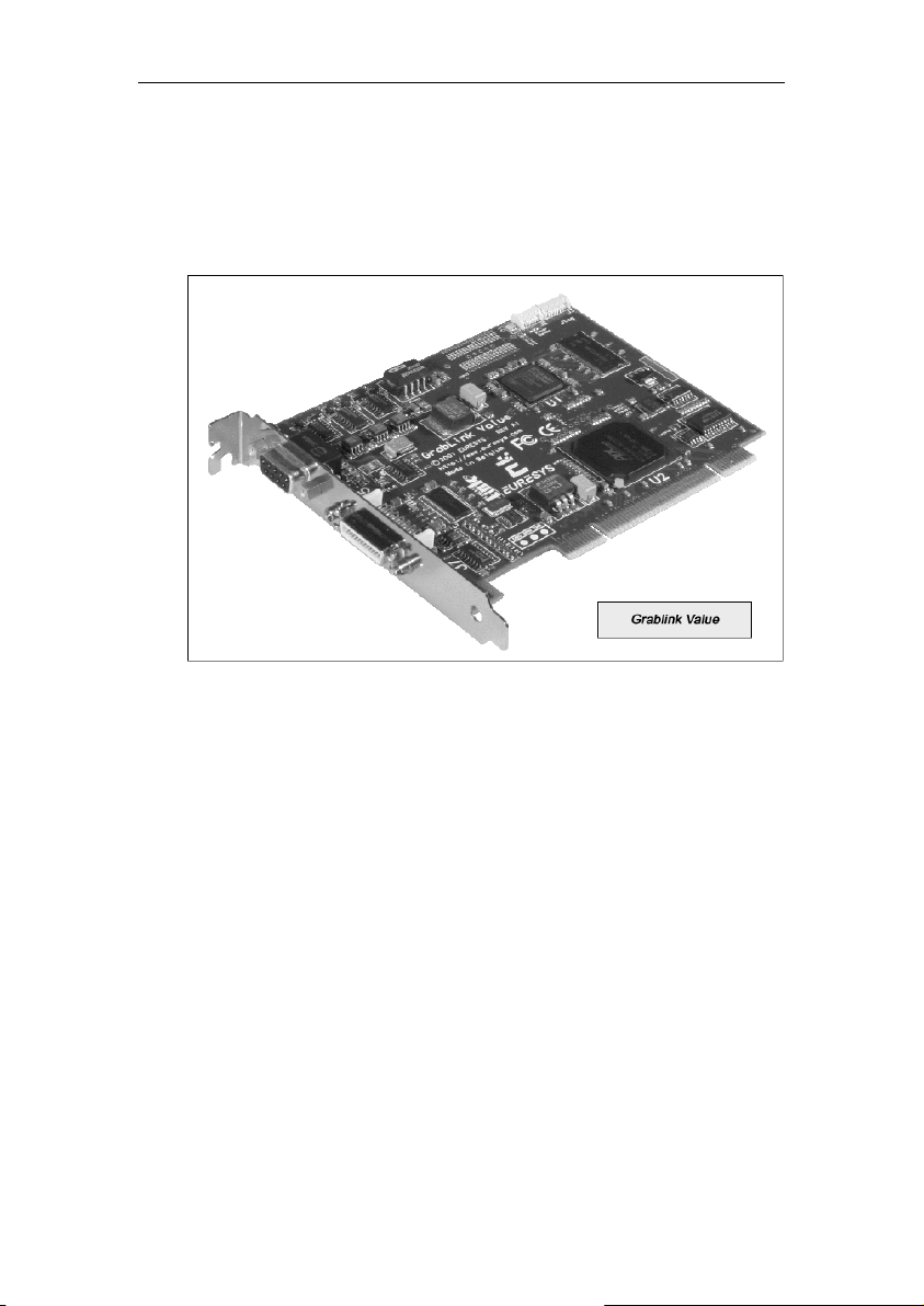
GRABLINK Value Description
GRABLINK Value Description
Product presentation
Grablink Value is an affordable Camera Link frame grabber for cost-effective industrial
applications. Grablink Value is recommended for single-camera systems. It acquires images at a
maximum camera speed of 60 MHz over the data path towards the on-board memory.
15
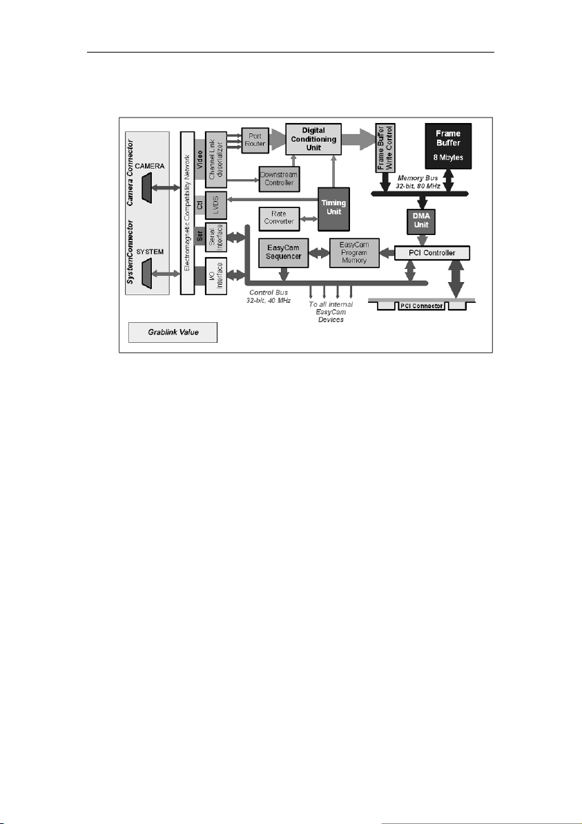
Block diagram
GRABLINK Value Description
16
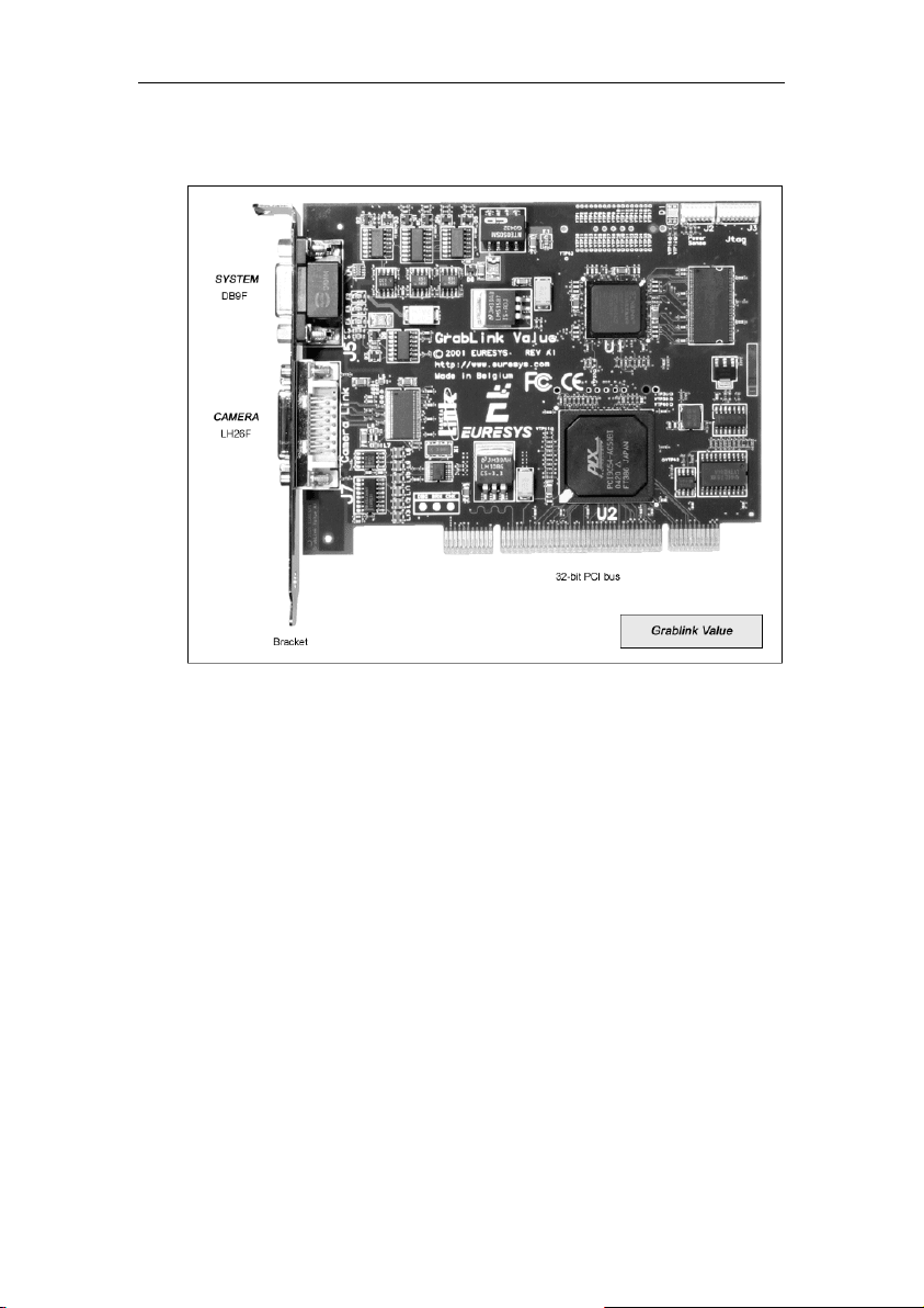
Board layout
GRABLINK Value Description
17
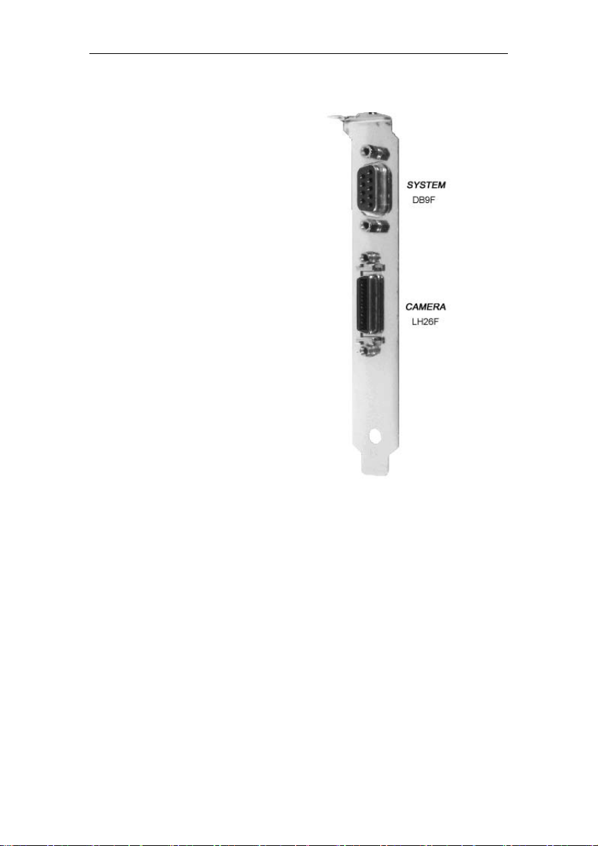
Bracket layout
The bracket attached to Grablink Value
provides two connectors.
The upper connector is for system connection,
such as external trigger, illumination control or
motion encoder. It is a sub-D 9-pin female
connector.
This connector is called SYSTEM.
The lower connector is for camera connection.
It is a blade contact high-density 26-pin female
connector. It complies with the Camera Link
standard. Grablink Value fully supports the
Base configuration as per the standard.
This connector is called CAMERA.
In depth information is available in the
electronic documentation coming with Euresys
products. Grablink manuals are parts of
Euresys MultiCam documentation.
GRABLINK Value Description
18
GRABLINK Value Description
Camera connector
Grablink Value offers an on-board high-density 26-pin female sub-D connector named CAMERA
for camera connection.
In depth information is available in the electronic documentation coming with Euresys products.
Grablink manuals are parts of Euresys MultiCam documentation.
19
GRABLINK Value Description
System connector
Grablink Value provides an on-board 9-pin female sub-D connector named SYSTEM for system
connection, including opto-isolated trigger and strobe lines.
Installing interconnection cables to this connector is highly system dependent.
In depth information is available in the electronic documentation coming with Euresys products.
Grablink manuals are parts of Euresys MultiCam documentation.
20

GRABLINK Value Description
PCI requirements
PCI stands for "Peripheral Component Interconnect" and refers to standardized means to install
an add-on board inside a computer.
Grablink Value is a short-size PCI card to be inserted in a standard PCI slot inside a PC. The
PCI edge connector is compliant with the official PCI specification, revision 2.2. It is 32-bit wide,
operates at 33 MHz maximum and supports both 3.3 V and 5 V signaling systems.
Grablink Value can be used in a 33 MHz or 66 MHz PCI slot like in a 66 MHz, 100 MHz or
133 MHz PCI-X slot. Installing the board on a 66 MHz or faster bus will restrict the bus to
conventional PCI at 33 MHz for all PCI agents installed on this bus.
For more information about PCI and PCI-X, refer to the Euresys application note entitled "PCI
Bus Variation".
Grablink Value uses the +5tV and +12tV power supply rails provided by the PCI bus. The +12tV
supply is only provided to outside devices through the SYSTEM connector. The power
consumption on this rail is therefore user dependent and is protected by a 0.5tA circuit breaker
with automatic reset. On the SYSTEM connector, a positive 5tV voltage is also borrowed from
the PC supply. A circuit breaker of 1tA with automatic reset protects the 5tV power supply. An
isolated +5tV supply delivering 150t mA maximum is available.
21

GRABLINK Avenue Description
GRABLINK Avenue Description
Product presentation
Grablink Avenue is an ultra-fast PCI frame grabber for line-scan or area-scan digital Camera
Link cameras. It is ideal for industrial applications such as high-speed moving objects, web
inspection or high-resolution acquisition.
Grablink Avenue is a high-performance 64-bit, 66 MHz PCI bus board acquiring images from
one camera in the Camera Link Base configuration. This board acquires the 24-bit data, with any
tap structure, at the maximum speed of 85 MHz.
With line-scan cameras, Grablink Avenue guarantees a constant sensitivity of the image
regardless of the web speed variation, thanks to ADR*, a unique patented downweb resampler.
Grablink Avenue is equipped with various I/O lines.
* Patent pending
23

Block diagram
GRABLINK Avenue Description
24

Board layout
GRABLINK Avenue Description
25

Bracket layout
The bracket attached to Grablink Avenue
provides two connectors.
The upper connector is for system
connection, such as external trigger,
illumination control or motion encoder. It
is a high density 26-pin connector.
This connector is called SYSTEM.
The lower connector is for camera
connection. It is a blade contact highdensity 26-pin female connector. It
complies with the Camera Link standard.
Grablink Avenue fully supports the Base
configuration as per the standard.
This connector is called CAMERA.
In depth information is available in the
electronic documentation coming with
Euresys products. Grablink manuals are
parts of Euresys MultiCam
documentation.
GRABLINK Avenue Description
26

GRABLINK Avenue Description
Camera connector
Grablink Avenue offers an on-board high-density 26-pin female sub-D connector named
CAMERA for camera connection.
In depth information is available in the electronic documentation coming with Euresys products.
Grablink manuals are parts of Euresys MultiCam documentation.
27

GRABLINK Avenue Description
System connectors
External system connector
Grablink Avenue provides an on-board 26-pin connector named SYSTEM for system
connection, including opto-isolated trigger and strobe lines.
Installing interconnection cables to this connector is highly system dependent.
28

GRABLINK Avenue Description
Internal system connector
Grablink Avenue also provides an internal 26-pin connector for system connections.
In depth information is available in the electronic documentation coming with Euresys products.
Grablink manuals are parts of Euresys MultiCam documentation.
29

GRABLINK Avenue Description
PCI requirements
PCI stands for "Peripheral Component Interconnect" and refers to standardized means to install
an add-on board inside a computer.
Grablink Avenue is a short-size PCI card to be inserted in a standard PCI slot inside a PC. The
PCI edge connector is compliant with the official PCI specification, revision 2.2. It is 64-bit wide,
operates at 66tMHz maximum and supports both 3.3tV and 5tV signaling systems.
Grablink Avenue can be used in a 33 MHz or 66 MHz PCI slot like in a 66 MHz, 100 MHz or
133 MHz PCI-X slot. Installing the board on a PCI-X bus will restrict the bus to conventional PCI
at 66 MHz for all PCI agents installed on this bus.
For more information about PCI and PCI-X, refer to the Euresys application note entitled "PCI
Bus Variation".
Grablink Avenue uses the +5tV and +12tV power supply rails provided by the PCI bus. The
+12tV supply is only provided to outside devices through the SYSTEM connector. The power
consumption on this rail is therefore user dependent and is protected by a 0.5tA circuit breaker
with automatic reset. On the SYSTEM connector, a positive 5tV voltage is also borrowed from
the PC supply. A circuit breaker of 1tA with automatic reset protects the 5tV power supply. An
isolated +5tV supply delivering 200tmA maximum is available.
30

GRABLINK Expert 2 Description
GRABLINK Expert 2 Description
Product presentation
Grablink Expert 2 is a Camera Link frame grabber for demanding industrial applications.
Supporting the Base or Medium configurations, it can be connected to one or two cameras.
Grablink Expert 2 is a 64-bit, 66 MHz PCI bus frame grabber. Each camera delivers images at a
maximum speed of 66 MHz over the data paths towards the on-board memory.
31

Block diagram
GRABLINK Expert 2 Description
32

Board layout
GRABLINK Expert 2 Description
33

GRABLINK Expert 2 Description
Bracket layout
The interconnection structure of Grablink
Expert 2 uses two brackets.
The bracket attached to Grablink Expert 2
provides two connectors.
They are both for camera connection. They are
blade contact high-density 26-pin female
connectors. They comply with the Camera Link
standard.
The upper connector is called CAMERAtB, while
the lower one is called CAMERAtA.
Grablink Expert 2 fully supports the Base and
Medium configurations as per the standard.
Refer to the following table:
Connector
Camera A
Camera B
Additional interconnection means are provided
on a separate card bracket. It is attached to an
auxiliary board linked to Grablink Expert 2 by a
26-wire ribbon cable.
The auxiliary bracket provides two connectors.
The upper connector is for general purpose
Input/Output connection. It is a sub-D 25-pin
female connector.
It is called I/O.
The lower connector is for system connection,
such as external trigger, illumination control or
motion encoder. It is a sub-D 9-pin female
connector.
This connector is called SYSTEM.
In depth information is available in the electronic
documentation coming with Euresys products.
Grablink manuals are parts of Euresys MultiCam
documentation.
Base
configuration
Used by first
camera
Used by
second
camera
configuration
Used
by
single
camera
Medium
Primary
Secondary
34

GRABLINK Expert 2 Description
Camera connectors
Grablink Expert 2 offers two on-board high-density 26-pin female sub-D connector for camera
connection. They are named CAMERA A and CAMERA B.
In depth information is available in the electronic documentation coming with Euresys products.
Grablink manuals are parts of Euresys MultiCam documentation.
35

GRABLINK Expert 2 Description
System connectors
Grablink Expert 2 provides two system connectors on a separate card bracket:
- A 9-pin female sub-D connector named SYSTEM for system connection, including optoisolated trigger and strobe lines.
- A 25-pin female sub-D connector named I/O for general purpose Input/Output connection.
36

GRABLINK Expert 2 Description
Installing interconnection cables to this connector is highly system dependent.
In depth information is available in the electronic documentation coming with Euresys products.
Grablink manuals are parts of Euresys MultiCam documentation.
37

GRABLINK Expert 2 Description
PCI requirements
PCI stands for "Peripheral Component Interconnect" and refers to standardized means to install
an add-on board inside a computer.
Grablink Expert 2 is a medium-size PCI card to be inserted in a standard PCI slot inside a PC.
The PCI edge connector is compliant with the official PCI specification, revision 2.2. It is 64-bit
wide, operates at 66 MHz maximum and supports both 3.3 V or 5 V signaling systems.
Grablink Expert 2 can be used in a 33 MHz or 66-MHz PCI slot like in a 66 MHz, 100 MHz or
133 MHz PCI-X slot. Installing the board on a PCI-X bus will restrict the bus to conventional PCI
at 66 MHz for all PCI agents installed on this bus.
For more information about PCI and PCI-X, refer to the Euresys application note entitled "PCI
Bus Variation".
Grablink Expert 2 uses the +5tV and +12tV power supply rails provided by the PCI bus. The
+12tV supply is only provided to outside devices through the SYSTEM connector. The power
consumption on this rail is therefore user dependent and is protected by a 0.5tA circuit breaker
with automatic reset. On the SYSTEM connector, a positive 5tV voltage is also borrowed from
the PC supply. A circuit breaker of 1tA with automatic reset protects the 5tV power supply. An
isolated +5tV supply delivering 200tmA maximum is available.
38

GRABLINK Value cPCI Description
GRABLINK Value cPCI Description
Product presentation
Grablink Value cPCI is an affordable Camera Link frame grabber for cost-effective industrial
applications. Grablink Value cPCI is recommended for single-camera systems. It acquires
images at a maximum camera speed of 60 MHz over the data path towards the on-board
memory.
Grablink Value cPCI is a 6U, 4HP CompactPCI card to be inserted in a standard CompactPCI
slot inside an industrial PC.
Grablink Value cPCI versus Grablink Value
Grablink Value cPCI and Grablink Value have basically identical characteristics. The physical
dimensions of the respective boards are obviously different.
The standard 32-bit, 33 MHz PCI connector of Grablink Value is replaced by a 64-bit, 66 MHz
CompactPCI connector on Grablink Value cPCI. Other connectors are identical.
Four LEDs are present only on Grablink Value cPCI. Their meaning is explained in the bracket
description chapter (see following pages).
All other characteristics are identical.
39

Block diagram
GRABLINK Value cPCI Description
40

Board layout
GRABLINK Value cPCI Description
41

GRABLINK Value cPCI Description
Bracket layout
The bracket attached to Grablink Value cPCI
provides two connectors.
The upper connector is for system connection,
such as external trigger, illumination control or
motion encoder. It is a sub-D 9-pin female
connector.
This connector is called SYSTEM.
A red/green pair of LEDs called Status LEDs
shows the global status of the frame grabber.
When the green LED is lighting (ON), MultiCam
is correctly started. If the red LED is lighting
(ON), that is a board-wide error has appeared.
A second red/green pair of LEDs called LEDs
for CAMERA gives information about each
camera acquisition. The green LED is lighting
(ON) during expose and readout phases of a
sequence. If the red LED is lighting (ON), that
is a channel acquisition error has appeared
during the sequence.
The lower connector is for camera connection.
It is a blade contact high-density 26-pin female
connector. It complies with the Camera Link
standard. Grablink Value cPCI fully supports
the Base configuration as per the standard.
This connector is called CAMERA.
In depth information is available in the
electronic documentation coming with Euresys
products. Grablink manuals are parts of
Euresys MultiCam documentation.
42

GRABLINK Value cPCI Description
Camera connector
Grablink Value cPCI offers an on-board high-density 26-pin female sub-D connector named
CAMERA for camera connection.
This connector is identical to the camera connector of Grablink Value.
In depth information is available in the electronic documentation coming with Euresys products.
Grablink manuals are parts of Euresys MultiCam documentation.
43

GRABLINK Value cPCI Description
System connector
Grablink Value cPCI provides an on-board 9-pin female sub-D connector named SYSTEM for
system connection, including opto-isolated trigger and strobe lines.
This connector is identical to the system connector of Grablink Value.
Installing interconnection cables to this connector is highly system dependent.
In depth information is available in the electronic documentation coming with Euresys products.
Grablink manuals are parts of Euresys MultiCam documentation.
44

GRABLINK Value cPCI Description
PCI requirements
PCI stands for "Peripheral Component Interconnect" and refers to standardized means to install
an add-on board inside a computer.
Grablink Value cPCI is a 6U, 4HP CompactPCI card to be inserted in a standard CompactPCI
slot inside an industrial PC. The CompactPCI connector is compliant with the official
CompactPCI specification PICMG 2.0 R3.0 dated October 1, 1999. It is 64-bit wide, operates at
66 MHz maximum and supports both 3.3 V and 5 V signaling systems.
Grablink Value cPCI can be used in a 33 MHz or 66 MHz CompactPCI slot and used in a
CompactPCI slot with either 32-bit or 64-bit.
For more information about PCI and PCI-X, refer to the Euresys application note entitled "PCI
Bus Variation".
Grablink Value cPCI uses the +3.3tV, +5tV and +12tV power supply rails provided by the
CompactPCI bus. The +12tV supply is only provided to outside devices through the SYSTEM
connector. The power consumption on this rail is therefore user dependent and is protected by a
0.5tA circuit breaker with automatic reset. On the SYSTEM connector, a positive 5tV voltage is
also borrowed from the PC supply. A circuit breaker of 1tA with automatic reset protects the 5tV
power supply. An isolated +5tV supply delivering 150tmA maximum is available.
45


GRABLINK Expert 2 cPCI Description
GRABLINK Expert 2 cPCI Description
Product presentation
Grablink Expert 2 cPCI is a Camera Link frame grabber for demanding industrial applications.
Supporting the Base or Medium configurations, it can be connected to one or two cameras.
Grablink Expert 2 cPCI is a 64-bit, 66 MHz PCI bus frame grabber. Each camera delivers
images at a maximum speed of 66 MHz over the data paths towards the on-board memory.
Grablink Expert 2 cPCI is a 6U, 4HP CompactPCI card to be inserted in a standard CompactPCI
slot inside an industrial PC.
Grablink Expert 2 cPCI versus Grablink Expert 2
Grablink Expert 2 cPCI has basically the same characteristics than Grablink Expert 2 and its
auxiliary board. The physical dimensions of the respective boards are obviously different.
The standard 64-bit, 66 MHz PCI connector of Grablink Expert 2 is replaced by a 64-bit, 66 MHz
CompactPCI connector on Grablink Expert 2 cPCI. Other connectors are identical. Therefore,
Grablink Expert 2 cPCI includes I/O and SYSTEM connectors.
Six LEDs are present only on Grablink Expert 2 cPCI. Their meaning is explained in the bracket
description chapter (see following pages).
All other characteristics are identical.
47

Block diagram
GRABLINK Expert 2 cPCI Description
48

Board layout
GRABLINK Expert 2 cPCI Description
49

GRABLINK Expert 2 cPCI Description
Bracket layout
The bracket attached to Grablink Expert 2 cPCI
provides four connectors.
The upper connector is for system connection, such as
external trigger, illumination control or motion encoder.
It is a sub-D 9-pin female connector.
This connector is called SYSTEM.
A red/green pair of LEDs called Status LEDs shows
the global status of the frame grabber. When the
green LED is lighting (ON), MultiCam is correctly
started. If the red LED is lighting (ON), that is a boardwide error has appeared.
The second connector is for general purpose
Input/Output connection. It is a sub-D 25-pin female
connector.
It is called I/O.
The two bottom connectors are for camera connection.
They are blade contact high-density 26-pin female
connectors. They comply with the Camera Link
standard.
The upper connector is called CAMERAtB, while the
lower one is called CAMERAtA.
Grablink Expert 2 cPCI fully supports the Base and
Medium configurations as per the standard. Refer to
the following table:
Connector
Camera A
Camera B
Two red/green pairs of LEDs called LEDs for
CAMERA B and LEDs for CAMERA A, placed above
the concerned connector, give information about each
camera acquisition. The green LED is lighting (ON)
during expose and readout phases of a sequence. If
the red LED is lighting (ON), that is a channel
acquisition error has appeared during the sequence.
In depth information is available in the electronic
documentation coming with Euresys products.
Grablink manuals are parts of Euresys MultiCam
documentation.
Base
configuration
Used by first
camera
Used by
second camera
Medium configuration
Used by
single
camera
Primary
Secondary
50

GRABLINK Expert 2 cPCI Description
Camera connectors
Grablink Expert 2 cPCI offers two on-board high-density 26-pin female sub-D connector for
camera connection. They are named CAMERA A and CAMERA B.
These connectors are identical to the camera connectors of Grablink Expert 2.
In depth information is available in the electronic documentation coming with Euresys products.
Grablink manuals are parts of Euresys MultiCam documentation.
51

GRABLINK Expert 2 cPCI Description
System connectors
Grablink Expert 2 cPCI provides two system connectors :
- A 9-pin female sub-D connector named SYSTEM for system connection, including optoisolated trigger and strobe lines.
- A 25-pin female sub-D connector named I/O for general purpose Input/Output connection.
These connectors are identical to the system connectors of Grablink Expert 2.
52

GRABLINK Expert 2 cPCI Description
Installing interconnection cables to this connector is highly system dependent.
In depth information is available in the electronic documentation coming with Euresys products.
Grablink manuals are parts of Euresys MultiCam documentation.
53

GRABLINK Expert 2 cPCI Description
PCI requirements
PCI stands for "Peripheral Component Interconnect" and refers to standardized means to install
an add-on board inside a computer.
Grablink Expert 2 cPCI is a 6U, 4HP CompactPCI card to be inserted in a standard CompactPCI
slot inside an industrial PC. The CompactPCI connector is compliant with the official
CompactPCI specification PICMG 2.0 R3.0 dated October 1, 1999. It is 64-bit wide, operates at
66 MHz maximum and supports both 3.3 V and 5 V signaling systems.
Grablink Expert 2 cPCI can be used in a 33 MHz or 66 MHz CompactPCI slot and used in a
CompactPCI slot with either 32-bit or 64-bit.
For more information about PCI and PCI-X, refer to the Euresys application note entitled "PCI
Bus Variation".
Grablink Expert 2 cPCI uses the +3.3tV, +5tV and +12tV power supply rails provided by the
CompactPCI bus. The +12tV supply is only provided to outside devices through the SYSTEM
connector. The power consumption on this rail is therefore user dependent and is protected by a
0.5tA circuit breaker with automatic reset. On the SYSTEM connector, a positive 5tV voltage is
also borrowed from the PC supply. A circuit breaker of 1tA with automatic reset protects the 5tV
power supply. An isolated +5tV supply delivering 200tmA maximum is available.
54

GRABLINK series Installation Instructions
GRABLINK series Installation Instructions
Hardware installation procedure for Grablink Value,
Grablink Avenue and Grablink Expert 2
Grablink Value, Grablink Avenue and Grablink Expert 2 are PCI add-on boards. Before
operation, they must be physically inserted in an available PCI slot of your computer.
Grablink Value, Grablink Avenue and Grablink Expert 2 need no hardware setup adjustment
(switch or jumper).
Multiple Euresys boards can be hosted in the same computer, as long as slots are available.
Recommended installation procedure:
1. Switch-off the computer and all connected peripherals (monitor, printer...).
2. Discharge any static electricity that could be accumulated on your body. You can
achieve this by touching an unpainted metal part of the enclosure of your computer with
a bare hand. Make sure that the computer is linked to the AC power outlet with proper
earth connection.
3. Disconnect all cables from your computer, including AC power.
4. Open the computer enclosure to gain access to the PCI slots according to the
manufacturer instructions.
5. Locate an available PCI slot and remove the blank bracket associated with this location.
To achieve this, remove the securing screw and keep it aside for later use in the
procedure. Keep the blank bracket in a known place for possible re-use.
6. Unwrap the Grablink packing, take the board and carefully hold it. Avoid any contact of
the board with unnecessary items, including your clothes.
7. Gently insert the board in the targeted PCI slot, taking care to push it down fully into the
slot. If you experience some resistance, remove the board and repeat the operation.
You should attempt to make a perfect board-to-slot mechanical alignment for best
results. Ensure that the lower part of the bracket is inserted into the corresponding
enclosure fastening.
8. Secure the board with the saved screw.
9. For Grablink Expert 2, optionally install the auxiliary board (see following pages).
10. Close the computer enclosure according to the manufacturer instructions.
11. Establish the camera connection (see following pages).
55

GRABLINK series Installation Instructions
Auxiliary board installation
Grablink Expert 2 comes with an auxiliary board that includes an additional card bracket. It
provides highly convenient means for system connection not directly related to camera. Installing
this board is optional.
The auxiliary board needs no hardware setup adjustment (switch or jumper).
The auxiliary board must be installed in a free PC bracket location, as depicted in the drawing,
taking into account the length of the provided interconnecting ribbon cable.
Note. Install the bracket after installing Grablink Expert 2, with the same precautions.
Auxiliary board recommended installation procedure:
1. Choose an available location and remove the associated blank bracket. To achieve
this, remove the securing screw and keep it aside for later use in the procedure. Keep
the blank bracket in a known place for possible re-use.
2. Place the auxiliary board in the targeted location. Ensure that the lower part of the
bracket is inserting into the corresponding enclosure fastening.
3. Secure the auxiliary board with the saved screw.
4. Fasten the interconnecting ribbon cable on both sides. If necessary, bend this cable.
56

GRABLINK series Installation Instructions
Hardware installation procedure for Grablink Value cPCI
and Grablink Expert 2 cPCI
Grablink Value cPCI and Grablink Expert 2 cPCI are CompactPCI add-on boards. Before
operation, they must be physically inserted in an available CompactPCI slot of the industrial PC.
Multiple Euresys boards can be hosted in the same industrial PC, as long as slots are available.
Grablink Value cPCI and Grablink Expert 2 cPCI need no hardware setup adjustment (switch or
jumper).
Recommended installation procedure:
1. Switch-off the industrial PC and all connected peripherals (monitor, printer...).
2. Discharge any static electricity that could be accumulated on your body. You can
achieve this by touching an unpainted metal part of the enclosure of your industrial PC
with a bare hand. Make sure that the industrial PC is linked to the AC power outlet with
proper earth connection.
3. Locate an available CompactPCI slot and remove the blank front plate associated with
this location. Keep the blank front plate in a known place for possible re-use.
4. Unwrap the Grablink packing, take the board and carefully hold it. Avoid any contact of
the board with unnecessary items, including your clothes.
5. Prior to the installation of the board, disengage the insertion/extraction handles by first
unlocking the handles and pressing them down.
6. Gently insert the board in the chosen CompactPCI slot and, using the
insertion/extraction handles, ensure that it is properly seated in the backplane. The front
panel should be flush with the rack front and the insertion/extraction handles should be
locked.
7. Fasten the front panel retaining screws.
8. Establish the camera connection.
Recommended removal procedure:
1. Disconnect all cables that are connected to the board.
2. Loosen both of the front panel retaining screws.
3. Unlock the insertion/extraction handles.
4. Gently disengage the board from the backplane by pressing down on the
insertion/extraction handles and pull the board out of the CompactPCI slot ensuring that
the board does not make any contact with adjacent boards. If the insertion/extraction
handles do not move, it is that they are not unlock; unlock them and try again.
57

GRABLINK series Installation Instructions
Camera connection
Linking a camera to a Camera Link compliant frame grabber is very straightforward. Use a
Camera Link compliant cable and connect each end to the camera and the frame grabber.
Secure the connectors with provided screws.
Camera Link cable connectors are identical on both ends. The cable can be installed in either
direction. However, the cable does not exhibit a pin-to-pin parallel connecting scheme.
The maximum cable length is system dependent. The cable performance as well as the
transmission frequency may affect the maximum cable length. Refer to cable and camera
characteristics. A cable length of 5 meters (16.4 feet) can be reached in all situations.
Power supply should be provided externally in full accordance with the camera manufacturer
instructions.
In the Euresys proprietary cable designation system, the required cable is the following:
Cable Name Cable Designation
CameraLink Standard CL-C01-xx
"xx" is a two-digit number expressing the length of the cable in meters.
Always switch-off power to all pieces of equipment before connecting or disconnecting a camera
cable. Failing to do so may result in damage to the board and/or to the camera.
Refer to the following drawings to clarify the camera connection structure according to the
camera configuration.
58

GRABLINK series Installation Instructions
Base configuration of Grablink Value, Grablink Avenue
and Grablink Value cPCI
In accordance with the Camera Link standard, the Base configuration defines a camera linked to
the frame grabber with one standard cable.
59

GRABLINK series Installation Instructions
Base configurations of Grablink Expert 2 and Grablink
Expert 2 cPCI
In accordance with the Camera Link standard, the Base configuration defines a camera linked to
the frame grabber with one standard cable.
In this case, the Grablink Expert 2 board operates in the DuoCam mode, as two cameras are
handled simultaneously and independently.
60

GRABLINK series Installation Instructions
Medium configuration of Grablink Expert 2 and Grablink
Expert 2 cPCI
In accordance with the Camera Link standard, the Medium configuration defines a camera linked
to the frame grabber with two standard cables.
In this case, Grablink Expert 2 and Grablink Expert 2 cPCI operate in the MonoCam mode, as
only one camera is handled.
61


MultiCam Installation Instructions
MultiCam Installation Instructions
Hardware requirements
Following features are recommended to operate MultiCam:
CPU Pentium III Class or above
System memory Minimum 128 MB
Hard disk drive Minimum 150 MB free
Windows installation
Software requirements
MultiCam and Grablink boards can be operated on the following Microsoft Windows operating
systems.
OS version Additional information
Windows Server 2003 -
Windows XP Embedded -
Windows XP -
Windows 2000 Service Pack 2 or later
The development tools are C, C++, ActiveX and .NET* based. Thus all popular development
environments can be used to develop applications using Grablink boards and MultiCam.
Moreover, sample programs are provided for various development environments.
* Check the electronic documentation for details.
IDE version
In depth information about the supported development environment versions is
available in the electronic documentation coming with Euresys products.
The electronic documentation coming with Euresys products is provided in Microsoft standard
CHM format. Additional information can be provided as Adobe Acrobat PDF files.
Utilities File format
Internet Explorer 4 or later * For CHM files.
Adobe Acrobat Reader 4 or later * For PDF files.
* For your convenience, a version is provided on most Euresys CD-ROM.
Installation instructions
1. Switch-on your computer and start Windows. Log in with administrative rights.
2. If a Grablink board was newly added in the system, Windows "Hardware Installation
Wizard" will detect the board and possibly prompt for user action. Don't care about this
wizard.
63

MultiCam Installation Instructions
3. Place Euresys CD-ROM in the drive. The setup application starts automatically. If this is
not the case, run 'setup.exe' directly from the CD-ROM.
4. Select the option to install MultiCam.
5. Depending on the operating system, the installation procedure may differ. Follow
carefully the setup program instructions.
6. Check for proper installation: connect a camera to the Grablink board and run eVision
Evaluator.
Linux installation
Software requirements
MultiCam and Grablink boards can be operated on the following Linux operating systems.
OS version Additional information
RedHat 7.3 Kernel 2.4.18-3
RedHat 8.0 Kernel 2.4.18-14
The development tools are C or C++ based. Thus all popular development environments can be
used to develop applications using Grablink boards and MultiCam.
Moreover, sample programs are provided for various development environments.
IDE version
In depth information about the supported development environment versions is
available in the electronic documentation coming with Euresys products.
The electronic documentation coming with Euresys products is provided in standard CHM
format. Additional information can be provided as Adobe Acrobat PDF files.
Utilities File format
xchm For CHM files.
xpdf or Adobe Acrobat Reader 4 (or
later)
For PDF files.
Installation instructions
1. Switch-on your computer and start Linux.
2. Place Euresys CD-ROM in the drive and mount it.
3. Copy multicam-x.y.tar.gz on hard disk drive where x.y is the release version of
MultiCam.
Example: multicam-4.5.tar.gz
4. Extract the archive: # tar -xzvf multicam-x.y.tar.gz
5. Go into the MultiCam directory: # cd multicam-x.y
6. Log in as root.
7. Execute the installation script: # ./install
8. Check for proper installation: connect a camera to the Grablink board and run eVision
Evaluator.
64

Technical Specifications
Technical Specifications
Grablink Value technical specifications
Characteristics
Dimensions 132 mm x 103 mm
Power consumption 3.5 W
PCI capability 32-bit, 33 MHz, 3.3 V or 5 V signaling
Certification FCC class B and CE
Video connections
Operating conditions
Parameter Symbol Min Typ Max Units
Power supply +5V V
Ambient operating temperature TA 0 50 °C
Relative humidity 10 90 %
TTL input/output characteristics
Parameter Min Max Units
High level output voltage 4 5 V
High level output current 15 mA
Low level output voltage 0 600 mV
Low level output current 10 mA
Input current with TRa = +5V, if configured in
TTL input, high level (*)
Input current with TRa = GND, if configured in
TTL input, low level (*)
(*) The letter "a" is G, X, Y or Z.
Isolated input/output characteristics
1 Camera Link camera in Base
configuration
4.75 5.00 5.25 V
+5V
-1 mA
±1
µA
Parameter Min Max Units
High level output voltage 4.5 5.2 V
High level output current 8 mA
Low level output voltage 0 600 mV
Low level output current 100 mA
Input current if configured in 12V input, high level 5 mA
Input current if configured in 12V input, low level 50 mA
Input current if configured in TTL input, high level 200 mA
Input current if configured in TTL input, low level 2 mA
65

Technical Specifications
Power supply current requirements
Parameter Fuse Max Units
Frame grabber
consumption
Alimentation of
outside devices
Supply current for
+5V
Supply current for
+5V
Supply current for
isolated +5V
Supply current for
+12V
700 mA
1 A
150 mA
500 mA
66

Technical Specifications
Grablink Avenue technical specifications
Characteristics
Dimensions 168 mm x 107 mm
Power consumption tbd
PCI capability 64-bit, 66 MHz, 3.3 V or 5 V signaling
Certification FCC class B and CE
Video connections
Operating conditions
Parameter Symbol Min Typ Max Units
Power supply +5V V
Ambient operating temperature TA 0 50 °C
Relative humidity 10 90 %
TTL input/output characteristics
Parameter Min Max Units
High level output voltage 4 5 V
High level output current 15 mA
Low level output voltage 0 600 mV
Low level output current 10 mA
Input current with TRa = +5V, if configured in
TTL input, high level (*)
Input current with TRa = GND, if configured in
TTL input, low level (*)
(*) The letter "a" is G, X, Y or Z.
Isolated input/output characteristics
1 Camera Link camera in Base
configuration
4.75 5.00 5.25 V
+5V
-1 mA
±1
µA
Parameter Min Max Units
High level output voltage 4.5 5.2 V
High level output current 8 mA
Low level output voltage 0 600 mV
Low level output current 100 mA
Input current if configured in 12V input, high level 5 mA
Input current if configured in 12V input, low level 50 mA
Input current if configured in TTL input, high level 200 mA
Input current if configured in TTL input, low level 2 mA
67

Technical Specifications
Power supply current requirements
Parameter Fuse Max Units
Frame grabber
consumption
Alimentation of
outside devices
Supply current for
+5V
Supply current for
+5V
Supply current for
isolated +5V
Supply current for
+12V
700 mA
1 A
150 mA
500 mA
68

Technical Specifications
Grablink Expert 2 technical specifications
Characteristics
Dimensions 210 mm x 107 mm
Power consumption 6 W
PCI capability 64-bit, 66 MHz, 3.3 V or 5 V signaling
Certification FCC class B and CE
Video connections
The auxilliary board that can be connected to Grablink Expert 2 has following characteristics:
1 Camera Link camera in Medium
configuration or 2 Camera Link cameras in
Base configuration
Dimensions 32 mm x 107 mm
Power consumption 2 mW
Certification FCC class B and CE
Auxiliary board
Operating conditions
Parameter Symbol Min Typ Max Units
Power supply +5V V
Ambient operating temperature TA 0 50 °C
Relative humidity 10 90 %
TTL input/output characteristics
Parameter Min Max Units
High level output voltage 4 5 V
High level output current 15 mA
Low level output voltage 0 600 mV
Low level output current 10 mA
Input current with TRa = +5V or IOn, if configured
in TTL input, high level (*)
Input current with TRa = GND or IOn, if
configured in TTL input, low level (*)
(*) The letter "a" is G, X, Y or Z; the letter "n" is 1 to 16.
4.75 5.00 5.25 V
+5V
-1 mA
±1
µA
69

Technical Specifications
Isolated input/output characteristics
Parameter Min Max Units
High level output voltage 4.5 5.2 V
High level output current 8 mA
Low level output voltage 0 600 mV
Low level output current 100 mA
Input current if configured in 12V input, high level 5 mA
Input current if configured in 12V input, low level 50 mA
Input current if configured in TTL input, high level 200 mA
Input current if configured in TTL input, low level 2 mA
Power supply current requirements
Parameter Fuse Max Units
Frame grabber
consumption
Alimentation of
outside devices
Supply current for
+5V
Supply current for
+5V
Supply current for
isolated +5V
Supply current for
+12V
1.2 A
1 A
150 mA
500 mA
70

Technical Specifications
Grablink Value cPCI technical specifications
Characteristics
Dimensions 160 mm x 233 mm
Power consumption 4 W
PCI capability 64-bit, 66 MHz, 3.3 V or 5 V signaling
Certification FCC class B and CE
Video connections
Operating conditions
Parameter Symbol Min Typ Max Units
Power supply +5V V
Power supply +3.3V V
Ambient operating temperature TA 0 50 °C
Relative humidity 10 90 %
TTL input/output characteristics
Parameter Min Max Units
High level output voltage 4 5 V
High level output current 15 mA
Low level output voltage 0 600 mV
Low level output current 10 mA
Input current with TRa = +5V, if configured in
TTL input, high level (*)
Input current with TRa = GND, if configured in
TTL input, low level (*)
(*) The letter "a" is G, X, Y or Z.
Isolated input/output characteristics
1 Camera Link camera in Base
configuration
4.75 5.00 5.25 V
+5V
3.15 3.30 3.45 V
+3.3V
±1
-1 mA
µA
Parameter Min Max Units
High level output voltage 4.5 5.2 V
High level output current 8 mA
Low level output voltage 0 600 mV
Low level output current 100 mA
Input current if configured in 12V input, high level 5 mA
Input current if configured in 12V input, low level 50 mA
Input current if configured in TTL input, high level 200 mA
Input current if configured in TTL input, low level 2 mA
71

Technical Specifications
Power supply current requirements
Parameter Fuse Max Units
Frame grabber
consumption
Alimentation of
outside devices
Supply current for
+5V
Supply current for
+3.3V
Supply current for
+5V
Supply current for
isolated +5V
Supply current for
+12V
tbd A
tbd mA
1 A
150 mA
500 mA
72

Technical Specifications
Grablink Expert 2 cPCI technical specifications
Characteristics
Dimensions 160 mm x 233 mm
Power consumption 7 W
PCI capability 64-bit, 66 MHz, 3.3 V or 5 V signaling
Certification FCC class B and CE
Video connections
Operating conditions
Parameter Symbol Min Typ Max Units
Power supply +5V V
Power supply +3.3V V
Ambient operating temperature TA 0 50 °C
Relative humidity 10 90 %
TTL input/output characteristics
Parameter Min Max Units
High level output voltage 4 5 V
High level output current 15 mA
Low level output voltage 0 600 mV
Low level output current 10 mA
Input current with TRa = +5V or IOn, if configured
in TTL input, high level (*)
Input current with TRa = GND or IOn, if
configured in TTL input, low level (*)
(*) The letter "a" is G, X, Y or Z; the letter "n" is 1 to 16.
Isolated input/output characteristics
1 Camera Link camera in Medium
configuration or 2 Camera Link cameras in
Base configuration
4.75 5.00 5.25 V
+5V
3.15 3.30 3.45 V
+3.3V
±1
-1 mA
µA
Parameter Min Max Units
High level output voltage 4.5 5.2 V
High level output current 8 mA
Low level output voltage 0 600 mV
Low level output current 100 mA
Input current if configured in 12V input, high level 5 mA
Input current if configured in 12V input, low level 50 mA
Input current if configured in TTL input, high level 200 mA
Input current if configured in TTL input, low level 2 mA
73

Technical Specifications
Power supply current requirements
Parameter Fuse Max Units
Frame grabber
consumption
Alimentation of
outside devices
Supply current for
+5V
Supply current for
+3.3V
Supply current for
+5V
Supply current for
isolated +5V
Supply current for
+12V
tbd A
tbd mA
1 A
150 mA
500 mA
74
 Loading...