


Picolo.net
1669-DR Picolo.net HD1 (DIN rail)
1669-DW Picolo.net HD1 (Desktop/Wall)
HANDBOOK
© EURESYS s.a. 2017 - Document version 1.0.3002 built on 2017-10-03

Picolo.net Handbook
Terms of Use
EURESYS s.a. shall retain all property rights, title and interest of the documentation of the hardware and the
software, and of the trademarks of EURESYS s.a.
All the names of companies and products mentioned in the documentation may be the trademarks of their
respective owners.
The licensing, use, leasing, loaning, translation, reproduction, copying or modification of the hardware or the
software, brands or documentation of EURESYS s.a. contained in this book, is not allowed without prior notice.
EURESYS s.a. may modify the product specification or change the information given in this documentation at any
time, at its discretion, and without prior notice.
EURESYS s.a. shall not be liable for any loss of or damage to revenues, profits, goodwill, data, information systems or
other special, incidental, indirect, consequential or punitive damages of any kind arising in connection with the use
of the hardware or the software of EURESYS s.a. or resulting of omissions or errors in this documentation.
This documentation is provided with Picolo.net 1.0 (doc build 2017-10-03).
© 2017 EURESYS s.a.
2

Picolo.net Handbook
Contents
About This Document 6
Document Scope 6
Document Revision History 7
Short Description 8
Mechanical Specification 11
Product Pictures 12
Dimensions and Weight 13
Mounting Methods 14
Connectors Location and Markings 15
Connectors 18
SDI AUDIO/VIDEO IN Connector 19
HDMI AUDIO/VIDEO IN Connector 20
HDMI AUDIO/VIDEO OUT Connector 22
AUDIO IN Connector 24
AUDIO OUT Connector 25
LAN Connector 26
USB 1 Connector 27
USB 2 Connector 28
COM Connector 29
GPIO Connector 30
POWER IN Connector 31
LED Indicators 32
Switches 34
Electrical Specifications 35
Power Input 36
SDI Input Port 37
HDMI Input Port 38
HDMI Output Port 39
Analog Audio Input Port 40
Analog Audio Output Port 41
Alarm Input Port 42
Relay Output Port 43
3

Picolo.net Handbook
RS-232 COM Port 45
RS-422/RS-485 COM Port 46
USB Port 47
Environmental Specifications 48
Operating Conditions 49
Storage Conditions 50
Compliance 51
Functional Specifications 52
Video Specifications 53
Video Source Specification 56
Video Encoders Specification 58
Audio Specifications 61
Streaming Specifications 64
Network Specifications 67
System Integration Specifications 69
Temperature Monitor 70
Auto Setup Profiles 71
Time and Date 72
Access Control 74
Software Specifications 76
Software Components 77
Client Interfaces 80
Web Services 81
ONVIF Device Service 82
Proprietary Device Service 83
ONVIF Media Service 84
Proprietary Media Service 85
ONVIF Event Service 87
ONVIF PTZ Service 88
Proprietary PTZ Service 89
ONVIF Device IO Service 91
Proprietary Device IO Service 92
Web Pages 94
Home Page 95
Login Page 99
Media Profiles Page 100
Media Profile Page 101
4

Picolo.net Handbook
Configurations Page 106
Edit Video Encoder Configuration Page 114
Edit Audio Encoder Configuration Page 117
Edit Metadata Configuration Page 120
Digital Inputs & Relay Outputs Page 121
Audio Outputs Page 124
PTZ Page 125
Device Management Page 127
Network Tab 127
Time Tab 130
Discovery Tab 133
Maintenance Tab 134
Users Management Page 136
Hidden Pages 138
Check Status Page 138
Product Maintenance 139
Firmware Upgrade 139
Configuration Backup and Restore 139
Application Notes 140
Encrypted Media Storage 141
Purpose 141
eCryptfs Encryption Layer 142
eCryptfs Header Extent 143
Web Services 145
References 146
Appendix 147
Appendix 148
About ONVIF 148
Open Source Software 149
Precautions of Use 149
Firmware Naming Conventions 150
5

Picolo.net Handbook About This Document
About This Document
Document Scope
This document describes and explains how to use the functions of the following Picolo.net
products, product options and accessories when operated with firmware version 1.0
Picolo.net Products
Product S/N Prefix Icon
1669-DW Picolo.net HD1 (Desktop/Wall) HD1
1669-DR Picolo.net HD1 (DIN rail) HD1
Related Accessories
Product S/N Prefix Icon
1675 Power Supply for Picolo.net HD1
6

About This Document Picolo.net Handbook
Document Revision History
Date Version Description
2017-10-03 1.0.3002 1669 Picolo.net HD1 Handbook initial release
7

Picolo.net Handbook Short Description
Short Description
KEY FEATURES
1669 Picolo.net HD1 provides the following key features:
n High-quality HEVC (H.265) / AVC (H.264) encoder, up to 9 encoded streams
n Video streaming from one full HD (up to 1080p60/1080i60) HDMI or SDI source
n ONVIF Profile S and Profile T interface
n Video encryption
n Hi-Fi AAC or uncompressed audio
n USB edge storage / USB GPS support
n Serial connection for PTZ cameras
n PoE+ Power over Ethernet
n Fanless aluminum housing
VIDEO FEATURES
1669 Picolo.net HD1 acquires high-definition video from one of HDMI or SDI video sources.
It supports progressive-scan formats up to 1080p60 and interlaced formats up to 1080i60 with a
large set of frame rates for both 50Hz and 60Hz regions. The source selection and the format
selection are automatic.
Interlaced-scan video streams are converted to progressive-scan with motion-compensation.
Two scalers provide two additional video stream sources at lower (or higher) resolutions :
n The scaler #1 scales the source resolution to 1280 x 720 (720p) (or lower).
n The scaler #2 scales the source resolution to 640 x 360 (360p) (or lower).
The three streams can be encoded concurrently with any of the following encoding methods:
n HEVC (H.265) main profile,
n AVC (H.264) baseline, main, or high profiles,
n MJPEG.
The high-quality HEVC (H.265) / AVC (H.264) hardware encoder engine is capable of encoding
multiple streams with an aggregate pixel rate up to 160,000,000 pixels per second (equivalent to
1080p77).
The MJPEG encoder is capable of encoding multiple streams with an aggregate pixel rate up to
62,208,000 pixels per second (equivalent to 1080p30).
8

Short Description Picolo.net Handbook
AUDIO FEATURES
1669 Picolo.net HD1 acquires 2-channel audio from one of HDMI, SDI or analog audio sources.
The source selector provides three options:
n HDMI: two digital audio channels embedded in the HDMI audio/video signal,
n SDI: two digital audio channels are embedded in the SDI audio/video signal,
n Analog: two digital audio channels delivered by the 48 kHz 16-bit analog-to-digital converter
in the analog audio input interface.
The sample rate converter allows to change the sample rate of the selected audio stream. The
resulting audio stream can be delivered in the uncompressed format (e.g. 16-bit LPCM), in the
AAC-LC compressed format or in the G.711 format.
IO FEATURES
1669 Picolo.net HD1 provides the following I/O features:
n 2 USB 2.0 ports for external storage device and GPS receiver,
n 2 serial COM ports for the control of PTZ cameras: one with a full-duplex RS-422/half-duplex
RS-485 interface using the Pelco-D protocol and one with a full-duplex RS-232 interface using
the VISTA protocol.
n 1 alarm input port,
n 1 relay output port.
NETWORK FEATURES
1669 Picolo.net HD1 provides a gigabit capable RJ-45 Ethernet port for connection to an IP
network.
STREAMING FEATURES
1669 Picolo.net HD1 uses the Real-time Transport Protocol - RTP - to stream audio, video and
metadata over the IP network. The following RTP transport modalities are supported:
n RTP over UDP Unicast
n RTP over UDP Multicast
n RTP interleaved in RTSP over HTTP or HTTPS
The streaming is controlled by means of the RTSP protocol. Each RTSP session may include:
n One encoded video stream
n One encoded audio stream
n One metadata stream
9

Picolo.net Handbook Short Description
USER AUTHENTICATION AND ACCESS POLICY
1669 Picolo.net HD1 implements the following user authentication mechanisms to control the
access to its resources:
n HTTP and RTSP authentication using the "HTTP Digest Authentication" mechanism
n WS authentication using the WS-Security “Username Token” mechanism, with the “Password
Digest” password type.
n Web Pages through login/password dialog box.
ENCRYPTION
1669 Picolo.net HD1 implements the following encryption mechanisms:
n Web Service messages encryption using TLS 1.0
n HTTPS Web Pages encrypted access using TLS 1.0
COMPLIANCE
1669 Picolo.net HD1 is an encoder device complying with the version 1.0 of the ONVIF Profile S
Specification.
PHYSICAL
1669-DR Picolo.net HD1 (DIN rail) is packaged in an aluminum enclosure that can be fitted on a
DIN-rail.
1669-DW Picolo.net HD1 (Desktop/Wall) is packaged in an aluminum enclosure that can be
installed on a desktop or attached to any flat surface such as a wall.
1669 Picolo.net HD1 products are:
n intended for indoor use exclusively,
n fan-less devices that support ambient temperatures up to 50°C or 122°F,
n powered from an external 12V DC power source or from a PoE+ network device.
10

Mechanical Specification Picolo.net Handbook
Mechanical Specification
Product Pictures 12
Dimensions and Weight 13
Mounting Methods 14
Connectors Location and Markings 15
Connectors 18
LED Indicators 32
Switches 34
11
Picolo.net Handbook Mechanical Specification
Product Pictures
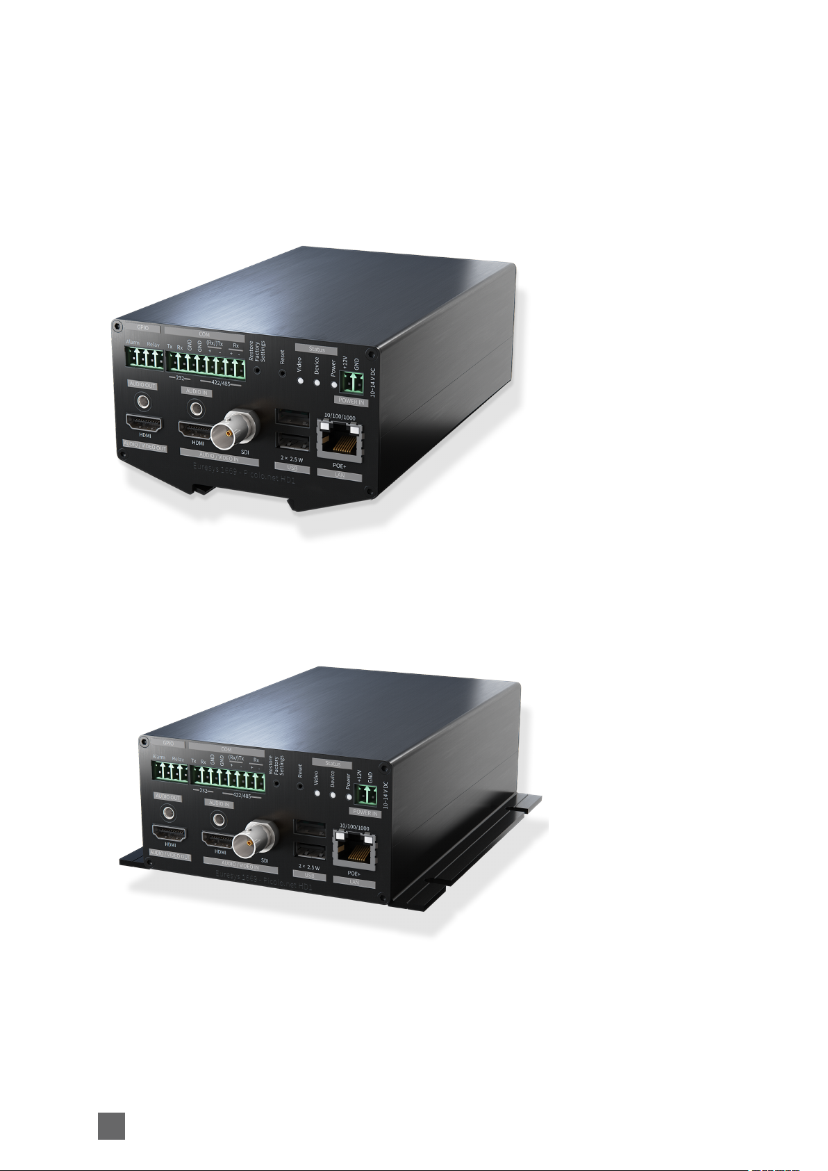
1669-DR PICOLO.NET HD1 (DIN RAIL)
Front panel perspective view
1669-DW PICOLO.NET HD1 (DESKTOP/WALL)
Front panel perspective view
12

Mechanical Specification Picolo.net Handbook
Dimensions and Weight
1669-DR PICOLO.NET HD1 (DIN RAIL)
Dimensions
Characteristic Value [mm] Value [inch]
Width 105 4.13
Height 63.9 2.52
Depth 185 7.28
Weight
Characteristic Value [g] Value [lb]
Weight 760 1.68
1669-DW PICOLO.NET HD1 (DESKTOP/WALL)
Dimensions
Characteristic Value [mm] Value [inch]
Width 130.4 5.13
Height 55.3 2.18
Depth 185 7.28
Weight
Characteristic Value [g] Value [lb]
Weight 800 1.76
13

Picolo.net Handbook Mechanical Specification
Mounting Methods
1669-DR PICOLO.NET HD1 (DIN RAIL)
The out-of-the box product is ready for installation on a DIN rail.
DIN-Rail Mount
The DIN rail must be horizontal. Two possible orientations are allowed: left facing connectors or
right facing connectors.
1669-DW PICOLO.NET HD1 (DESKTOP/WALL)
The out-of-the box product is ready for a desktop or a wall-mount usage. The enclosure is fitted
with 4 oblong holes, 2 on each side, that can be used to attach the product on any flat surface.
14

Mechanical Specification Picolo.net Handbook
Connectors Location and Markings
15
Picolo.net Handbook Mechanical Specification
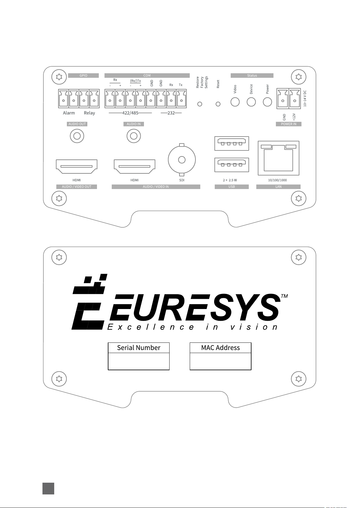
1669-DR PICOLO.NET HD1 (DIN RAIL)
Front panel
Rear panel
16
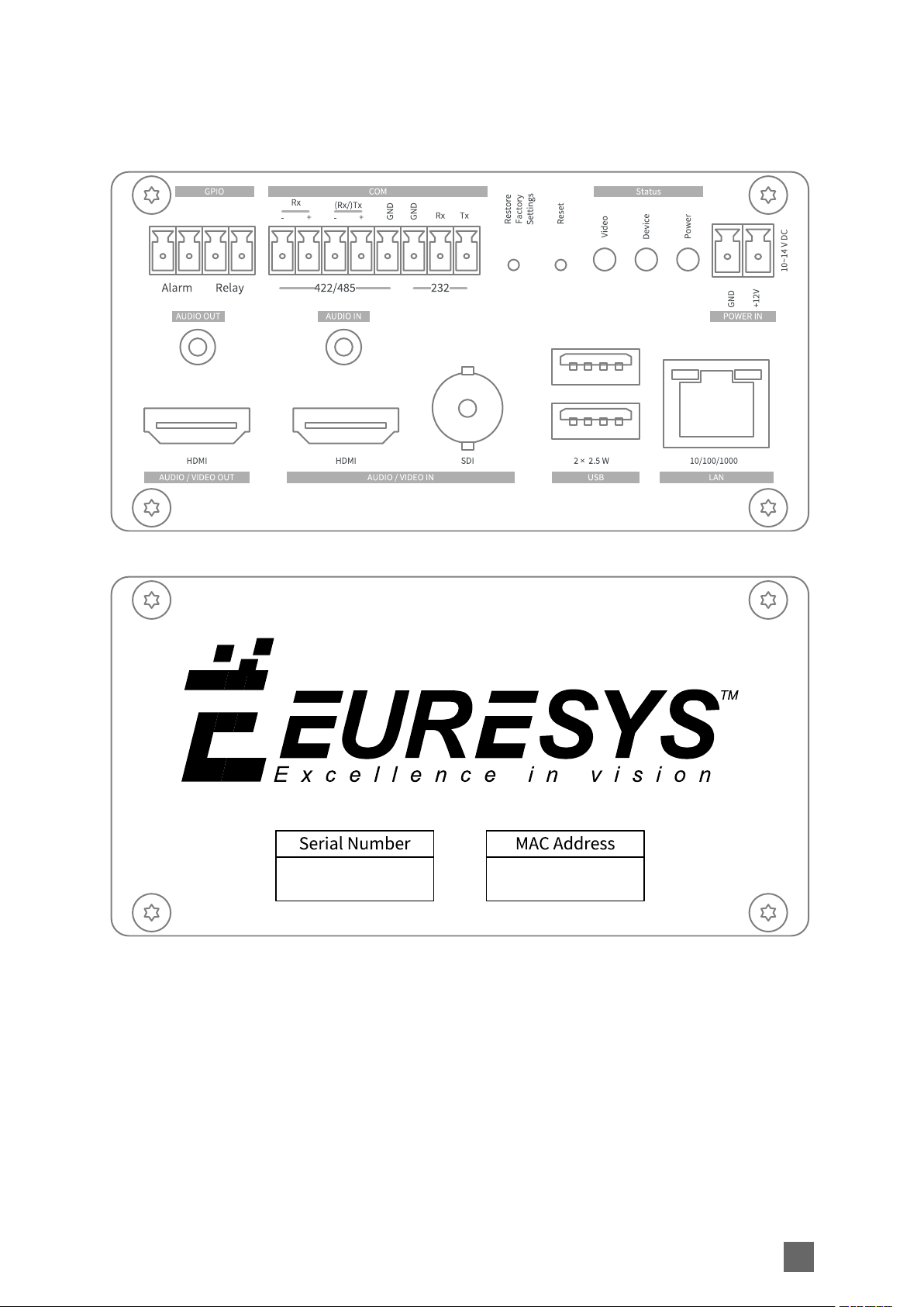
1669-DW PICOLO.NET HD1 (DESKTOP/WALL)
Front panel
Mechanical Specification Picolo.net Handbook
Rear panel
17

Picolo.net Handbook Mechanical Specification
Connectors
SDI AUDIO/VIDEO IN Connector 19
HDMI AUDIO/VIDEO IN Connector 20
HDMI AUDIO/VIDEO OUT Connector 22
AUDIO IN Connector 24
AUDIO OUT Connector 25
LAN Connector 26
USB 1 Connector 27
USB 2 Connector 28
COM Connector 29
GPIO Connector 30
POWER IN Connector 31
18
Mechanical Specification Picolo.net Handbook
SDI AUDIO/VIDEO IN Connector
Applies to:
Connector description
Property Value
Name SDI AUDIO/VIDEO IN
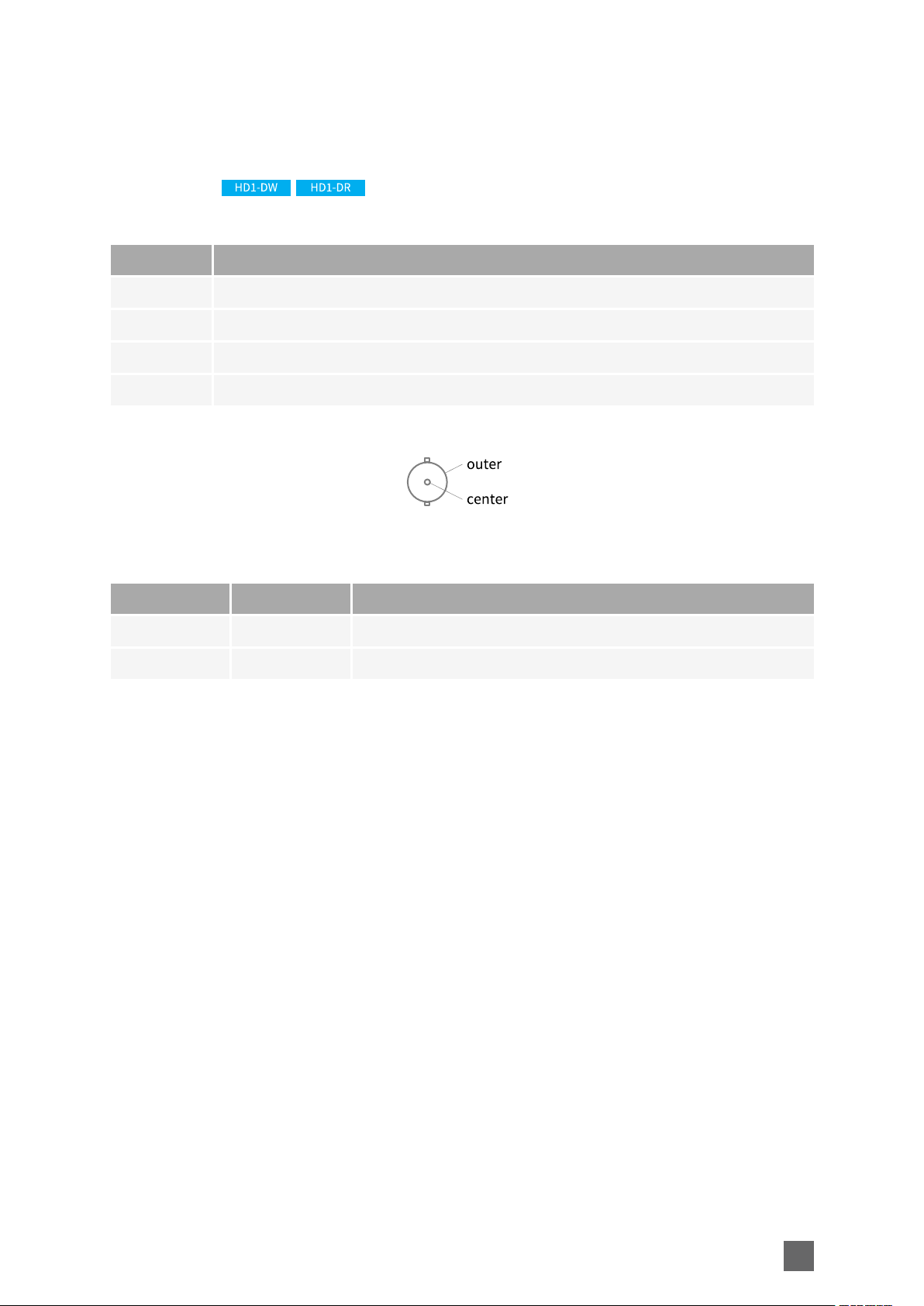
Type 2-pin female receptacle, right-angled PCB-mount, BNC connector
Location Front panel
Usage HD/3G-SDI audio/video input
Pin assignments
Pin Signal Usage
Center SDI IN SD/HD/3G-SDI Audio/Video Input
Outer GND Ground
19

Picolo.net Handbook Mechanical Specification
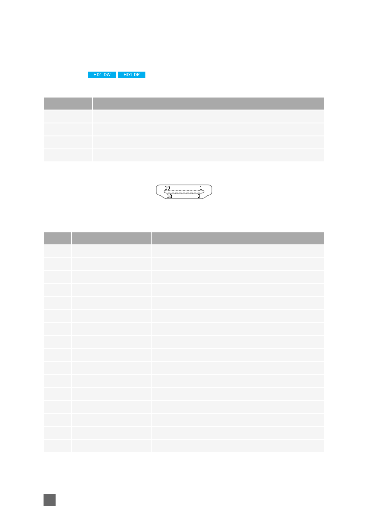
HDMI AUDIO/VIDEO IN Connector
Applies to:
Connector description
Property Value
Name HDMI AUDIO/VIDEO IN
Type HDMI type A (full size) receptacle (female) connector
Location Front panel
Usage HDMI audio/video input
Pin assignments
Pin Signal Usage
1 TMDS Data2 + Digital audio/video input TMDS data lane 2
2 TMDS Data2 Shield Shield
3 TMDS Data2- Digital audio/video input TMDS data lane 2
4 TMDS Data1+ Digital audio/video input TMDS data lane 1
5 TMDS Data1 Shield Shield
6 TMDS Data1- Digital audio/video input TMDS data lane 1
7 TMDS Data0+ Digital audio/video input TMDS data lane 0
8 TMDS Data0 Shield Shield
9 TMDS Data0- Digital audio/video input TMDS data lane 0
10 TMDS Clock+ Digital audio/video input TMDS clock lane
11 TMDS Clock Shield Shield
12 TMDS Clock- Digital audio/video input TMDS clock lane
13 -
14 -
15 SCL DDC serial clock
16 SDA DDC serial data
20

Pin Signal Usage
17 Ground DDC Ground
18 +5V
19 HPD Hot Plug Detect
Shell Chassis ground Shield
Mechanical Specification Picolo.net Handbook
21
Picolo.net Handbook Mechanical Specification
HDMI AUDIO/VIDEO OUT Connector
Applies to:
Connector description
Property Value
Name HDMI AUDIO/VIDEO OUT
Type HDMI type A (full size) receptacle (female) connector
Location Front panel
Usage HDMI audio/video output
Pin assignments
Pin Signal Usage
1 TMDS Data2 + Digital audio/video output TMDS data lane 2
2 TMDS Data2 Shield Shield
3 TMDS Data2- Digital audio/video output TMDS data lane 2
4 TMDS Data1+ Digital audio/video output TMDS data lane 1
5 TMDS Data1 Shield Shield
6 TMDS Data1- Digital audio/video output TMDS data lane 1
7 TMDS Data0+ Digital audio/video output TMDS data lane 0
8 TMDS Data0 Shield Shield
9 TMDS Data0- Digital audio/video output TMDS data lane 0
10 TMDS Clock+ Digital audio/video output TMDS clock lane
11 TMDS Clock Shield Shield
12 TMDS Clock- Digital audio/video output TMDS clock lane
13 -
14 -
15 SCL DDC serial clock
16 SDA DDC serial data
22

Pin Signal Usage
17 Ground DDC Ground
18 +5V
19 HPD Hot Plug Detect
Shell Chassis ground Shield
Mechanical Specification Picolo.net Handbook
23
Picolo.net Handbook Mechanical Specification
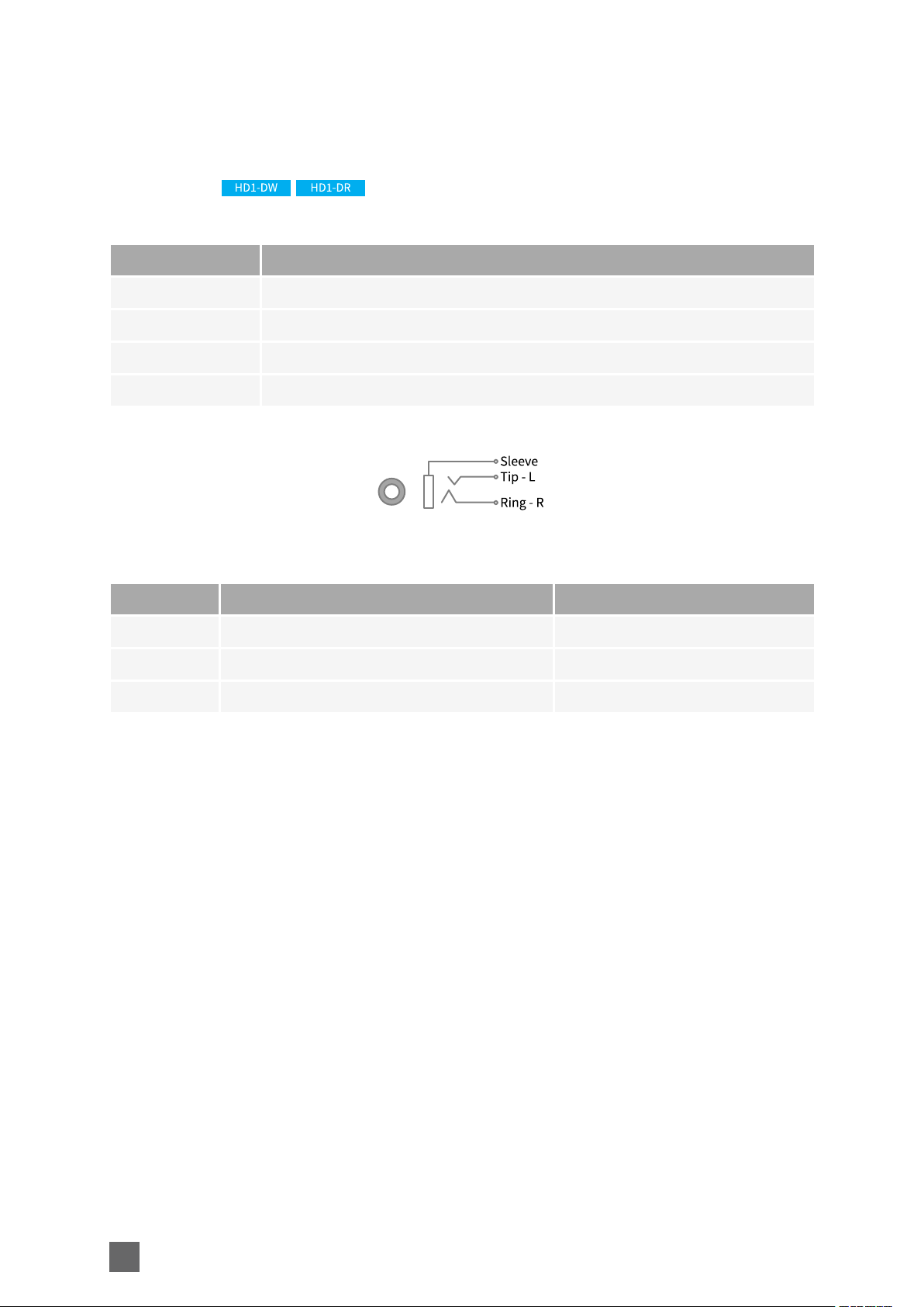
AUDIO IN Connector
Applies to:
Connector description
Property Value
Name AUDIO IN
Type Black TRS 3.5mm jack socket connector
Location Front panel
Usage Analog audio input
Pin assignments
Pin Signal Usage
Ring AUDIO IN - Right channel Unused
Tip AUDIO IN - Left channel Analog audio input
Sleeve GND Chassis ground
24
Mechanical Specification Picolo.net Handbook
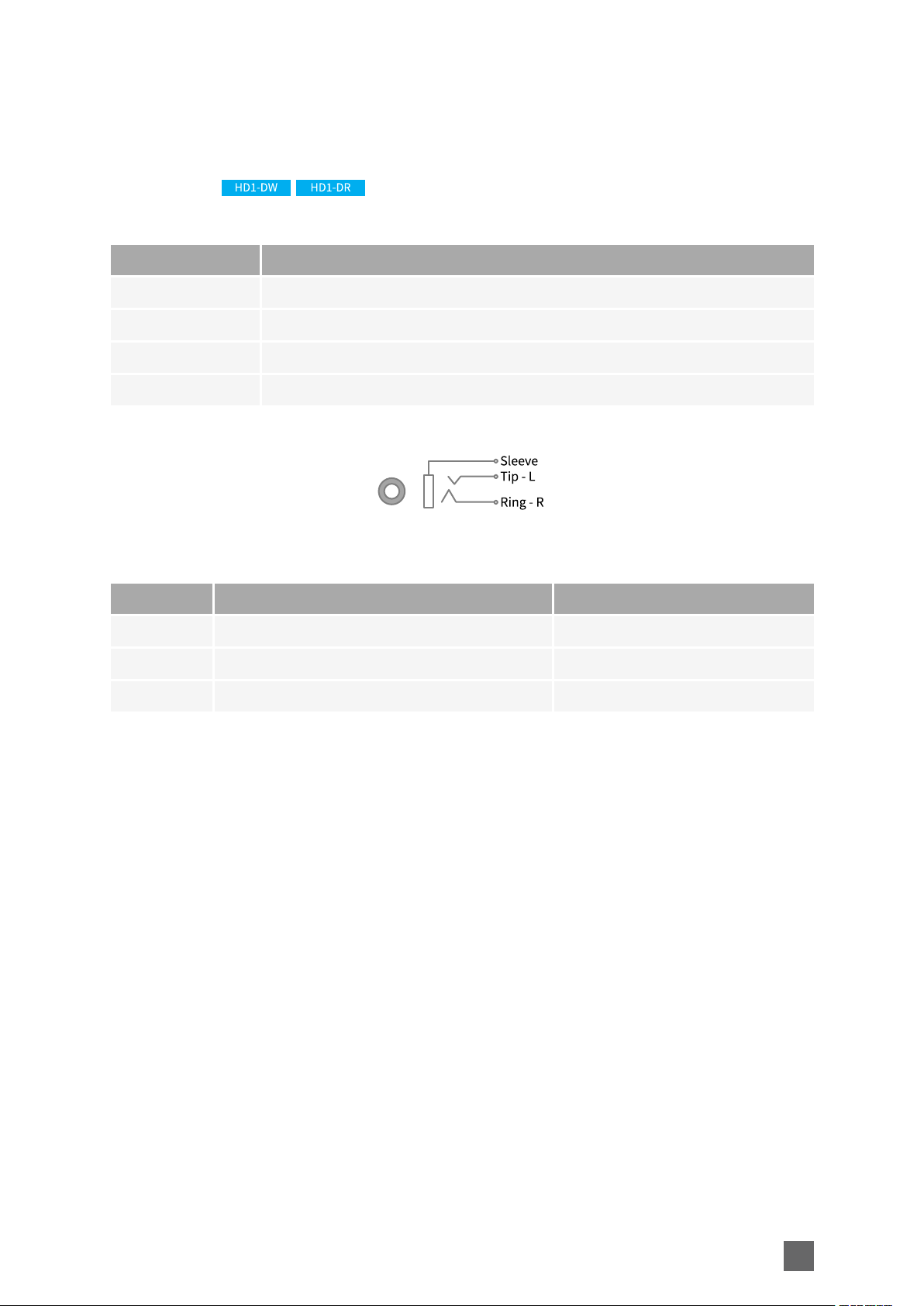
AUDIO OUT Connector
Applies to:
Connector description
Property Value
Name AUDIO OUT
Type Black TRS 3.5mm jack socket connector
Location Front panel
Usage Analog audio output
Pin assignments
Pin Signal Usage
Ring AUDIO OUT - Right channel Unused
Tip AUDIO OUT - Left channel Analog audio output
Sleeve GND Chassis ground
25
Picolo.net Handbook Mechanical Specification
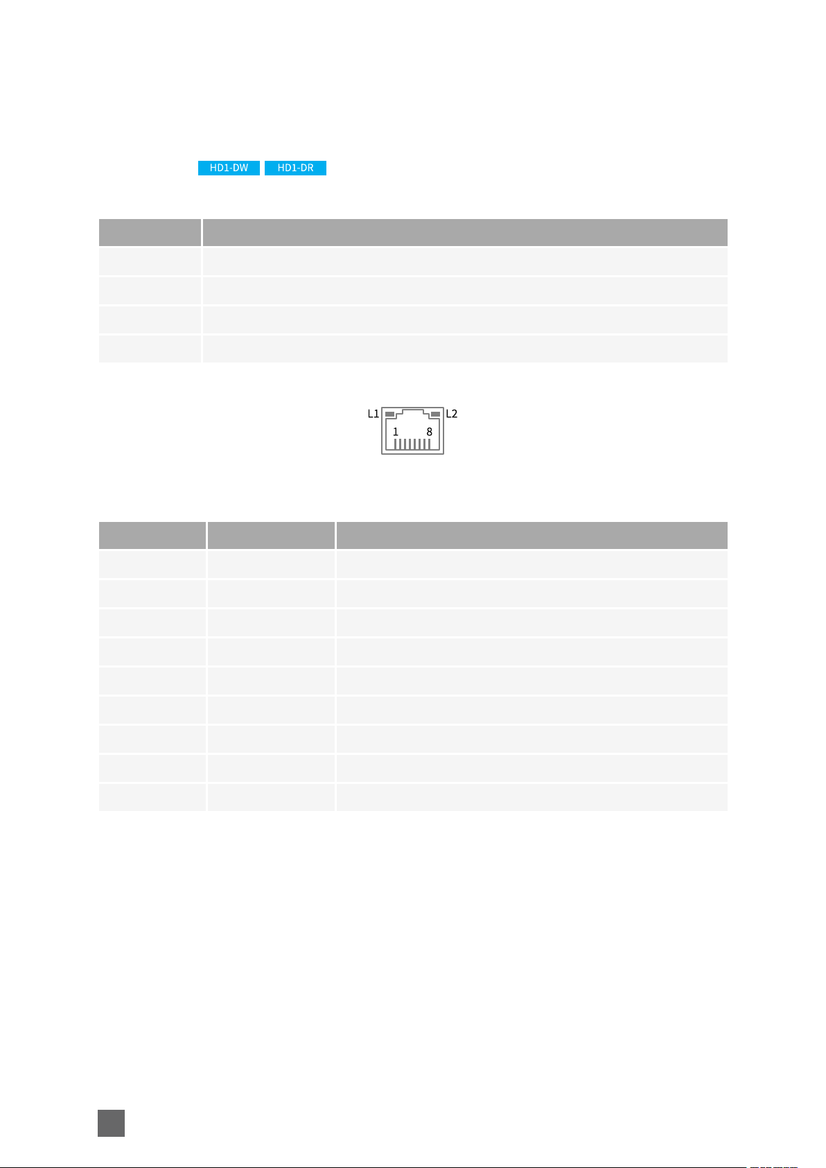
LAN Connector
Applies to:
Connector description
Property Value
Name LAN
Type 8-pin RJ45 jack connector with 2 built-in LED indicators
Location Front panel
Usage 10/100/1000 local area network
Pin assignments
Pin Signal Usage
1 TRP1+ Transmit/Receive Pair 1 +
2 TRP1- Transmit/Receive Pair 1 -
3 TRP2+ Transmit/Receive Pair 2 +
4 TRP3+ Transmit/Receive Pair 3 +
5 TRP3- Transmit/Receive Pair 3 -
6 TRP2- Transmit/Receive Pair 2 -
7 TRP4+ Transmit/Receive Pair 4 +
8 TRP4- Transmit/Receive Pair 4 -
Shell GND Ground
26
Mechanical Specification Picolo.net Handbook
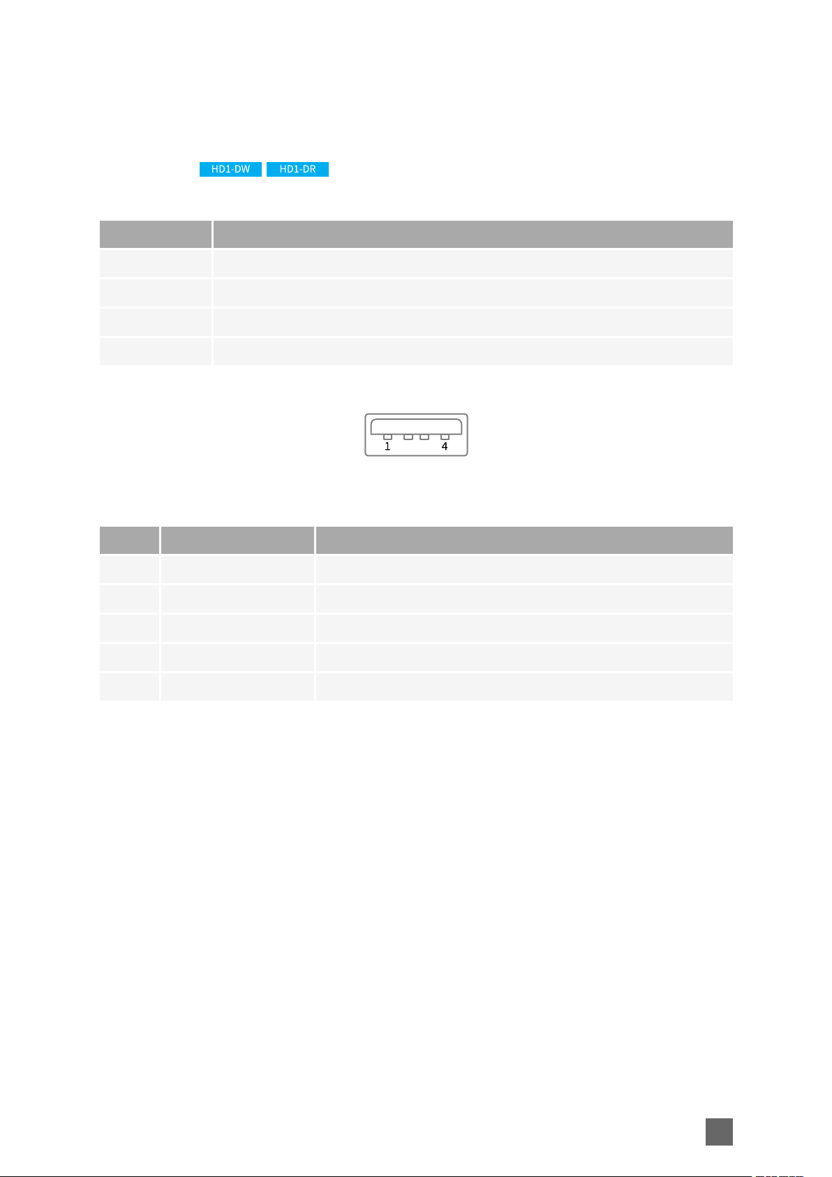
USB 1 Connector
Applies to:
Connector description
Property Value
Name USB 1
Type USB type A (full size) receptacle (female) connector
Location Front panel
Usage External storage, GPS, ...
Pin assignments
Pin Signal Usage
1 VCC +5V output
2 DATA- Data input/output – Negative terminal
3 DATA+ Data input/output – Positive terminal
4 GND Ground
5 Chassis GND Cable shield
27
Picolo.net Handbook Mechanical Specification
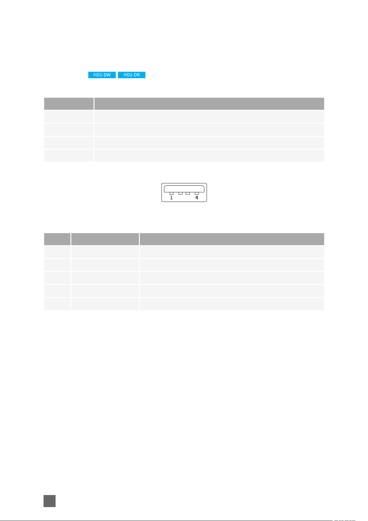
USB 2 Connector
Applies to:
Connector description
Property Value
Name USB 2
Type USB type A (full size) receptacle (female) connector
Location Front panel
Usage External storage, GPS, ...
Pin assignments
Pin Signal Usage
1 VCC +5V output
2 DATA- Data input/output – Negative terminal
3 DATA+ Data input/output – Positive terminal
4 GND Ground
5 Chassis GND Cable shield
28
Mechanical Specification Picolo.net Handbook
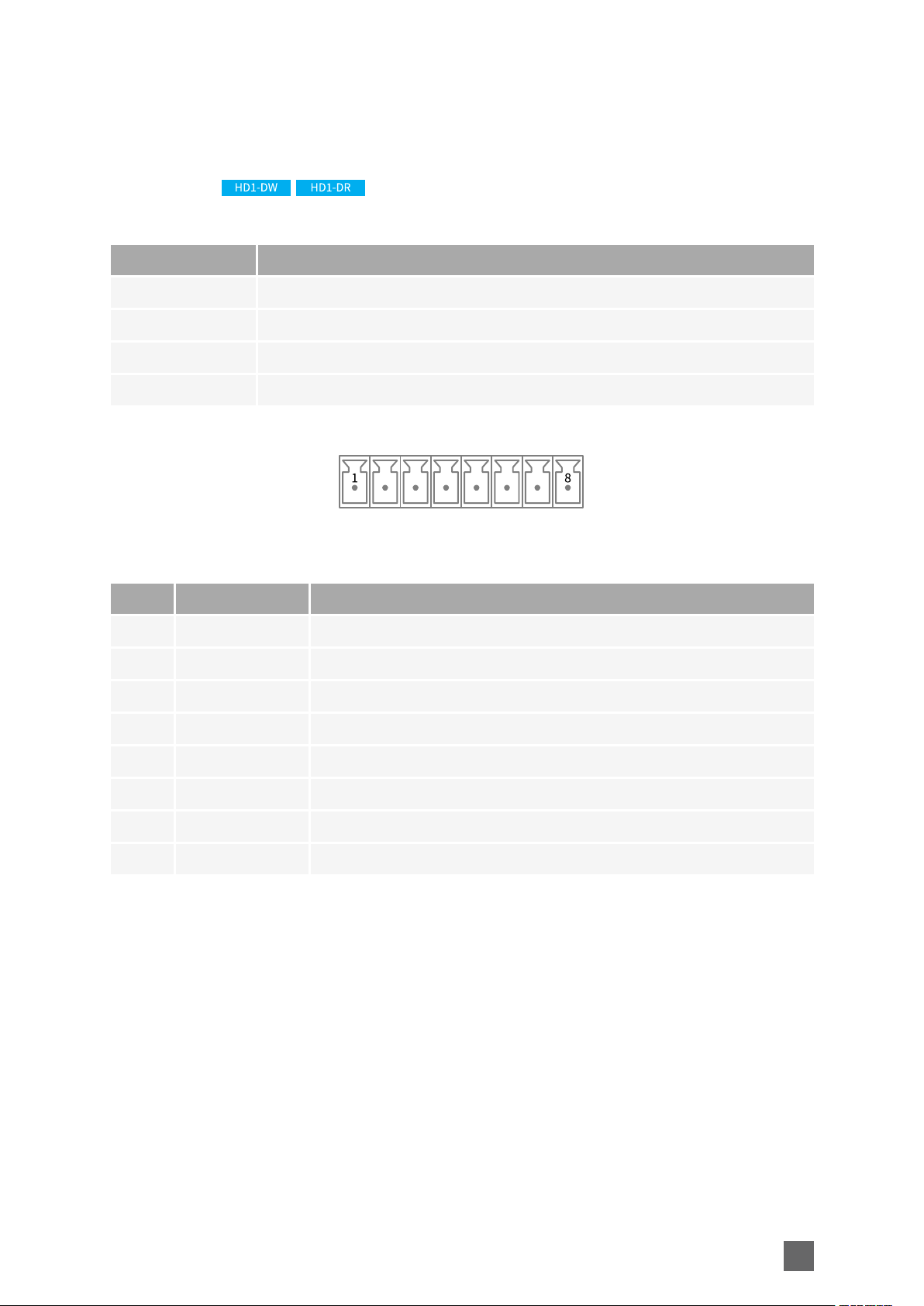
COM Connector
Applies to:
Connector description
Property Value
Name COM
Type 8-pin (1x8) 3.81mm pitch terminal socket
Location Front panel
Usage RS-232/RS-422/RS-485 serial COM port
Pin assignments
Pin Signal Usage
1 RxD- 422:RxD-(A)input
2 RxD+ 422:RxD+(B) input
3 (Rx/)TxD- 485:Data-(A) input/output 422:TxD-(A)output
4 (Rx/)TxD+ 485:Data+(B)input/output 422:TxD-(B)output
5 GND Cable shield
6 GND Cable shield
7 RxD 232:RxD input
8 TxD 232:TxD output
29
Picolo.net Handbook Mechanical Specification
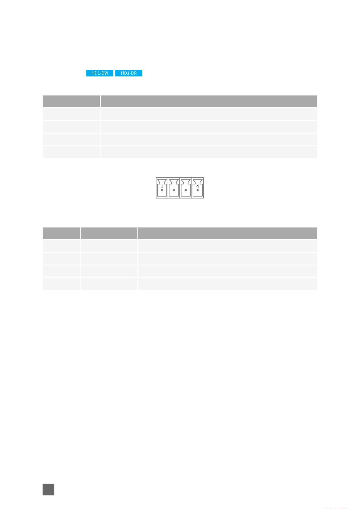
GPIO Connector
Applies to:
Connector description
Property Value
Name GPIO
Type 4-pin (1x4) 3.81mm pitch terminal socket
Location Front panel
Usage Alarm input and relay ouput
Pin assignments
Pin Signal Usage
1 INA Alarm Input - Terminal A
2 INB Alarm Input - Terminal B
3 OUTA Relay Output - Terminal A
4 OUTB Relay Output - Terminal B
30

Mechanical Specification Picolo.net Handbook
POWER IN Connector
Applies to:
Connector description
Property Value
Name POWER IN
Type 2-pin 3.81mm pitch terminal socket
Location Front panel
Usage DC power input
Pin assignments
Pin Signal Usage
1 GND DC Power Input - Ground terminal
2 + DC Power Input - Positive terminal
31

Picolo.net Handbook Mechanical Specification
LED Indicators
Applies to:
Front panel
Indicator Type and Colour Marking
Video Status Circular green LED Video
Device Status Circular bi-color red & green LED Device
Power Status Circular green LED Power
Link Activity
Link Status
Video Status states
State Meaning
OFF No or invalid video signal
ON Valid and supported video signal
Power Status states
State Meaning
OFF No power
ON Power OK
Rectangular amber LED (LAN
connector)
Rectangular green LED (LAN
connector)
No marking
No marking
Device Status states
State Meaning
OFF Power OFF or Operating System kernel startup
Green color, fast blink (10
Hz) 50% ON time
32
Operating System Kernel startup completed, system boot in
progress

State Meaning
Green color, ON System is Ready
Mechanical Specification Picolo.net Handbook
Orange color, slow blink
(1 Hz) 10% ON time
Orange color, fast blink
(10 Hz) 50% ON time
Red color, slow blink (1
Hz) 90% ON time
Red color, , fast blink (10
Hz) 50% ON time
LAN Link Activity states
Firmware update in progress
USB Service needed
System error
USB device with wrong power requirements detected or with
unknown class detected
State Meaning
OFF No activity on the link
Blink Activity on the link
LAN Link Status states
State Meaning
OFF The link is not OK
Blink The link is OK and operating at the lowest speed
ON The link is OK and operating at the highest speed
33

Picolo.net Handbook Mechanical Specification
Switches
Applies to:
Front panel
Switch Type Marking
Device Maintenance Recessed push-button Restore Factory Settings
Device Reset Recessed push-button Reset
Device Maintenance Switch action
Switch Action Meaning
Long push (t > 3 s after
the Device Status
indicator turns to the
orange state)
Device Reset Switch action
Switch Action Meaning
Push Reboot the device
Restore the device factory settings including network settings
34

Electrical Specifications Picolo.net Handbook
Electrical Specifications
Power Input 36
SDI Input Port 37
HDMI Input Port 38
HDMI Output Port 39
Analog Audio Input Port 40
Analog Audio Output Port 41
Alarm Input Port 42
Relay Output Port 43
RS-232 COM Port 45
RS-422/RS-485 COM Port 46
USB Port 47
35

Picolo.net Handbook Electrical Specifications
Power Input
Applies to:
DUAL POWER SOURCE
The device can be powered from 1 or 2 external power sources:
n A +12 V DC power source attached to the POWER IN connector and/or ...
n ... through the LAN connector and the network cable from a PoE+ (IEEE 802.3at-2009) capable
network switch.
Having two power sources ensures power supply redundancy: if one source fails, the device
automatically switches to the remaining source without any impact on the device
operation.
POWER REQUIREMENTS
Property Min. Typ. Max. Unit
POWER IN: DC voltage range 9 14 V
POWER IN: DC power consumption
(when no power is delivered to the LAN
connector)
POWER IN: Power supply ratings 20 W
LAN: PoE+ power consumption
(when no power is delivered to the POWER
IN connector)
The specification applies to the whole operating temperature range when the device
encodes audio and video at full encoding power.
10.5 W
10.5 W
36

Electrical Specifications Picolo.net Handbook
SDI Input Port
Applies to:
The SDI input port implements a single-link SDI sink interface for 3G-SDI and HD-SDI devices.
OPERATING CHARACTERISTICS
Property Min. Typ. Max. Unit
Peak-to-peak signal amplitude (short cable) 720 800 950 mV
Serial data rate 1.485 2.970 Gbps
Achievable cable length with Belden 1694
coaxial cable @1.485 Gbps
Achievable cable length with Belden 1694
coaxial cable @2.970 Gbps
Input impedance 75 Ω
ABSOLUTE MAXIMUM RATINGS
Property Min. Typ. Max. Unit
DC voltage -2.0 +2.0 V
Exceeding the above limits may irreversibly damage the product.
The usage of DC-coupled video sources outside the above mentioned limits is strictly
prohibited.
100 m
***TBD*** m
37

Picolo.net Handbook Electrical Specifications
HDMI Input Port
Applies to:
The HDMI input port implements a single TMDS link complying with the electrical specifications
of the High Definition Multimedia Interface 1.3 for HDMI Sink.
OPERATING CHARACTERISTICS
Property Min. Typ. Max. Unit
TMDS Clock Rate 25.175 165 MHz
ABSOLUTE MAXIMUM RATINGS
Property Min. Typ. Max. Unit
DC voltage -2.0 +2.0 V
Exceeding the above limits may irreversibly damage the product.
38

Electrical Specifications Picolo.net Handbook
HDMI Output Port
Applies to:
The HDMI output port implements a single TMDS link complying with the electrical
specifications of the High Definition Multimedia Interface 1.3 for HDMI Source.
OPERATING CHARACTERISTICS
Property Min. Typ. Max. Unit
TMDS Clock Rate 25.175 165 MHz
ABSOLUTE MAXIMUM RATINGS
Property Min. Typ. Max. Unit
DC voltage -2.0 +2.0 V
Exceeding the above limits may irreversibly damage the product.
39

Picolo.net Handbook Electrical Specifications
Analog Audio Input Port
Applies to:
The analog audio input port implements a high-impedance 2-channel line-level audio input
interface.
OPERATING CHARACTERISTICS
Property Min. Typ. Max. Unit
Full-scale input voltage 1.35 1.4 1.5 V
Input impedance (@ 1 kHz) 100 kΩ
Sampling frequency 48 kHz
ABSOLUTE MAXIMUM RATINGS
Property Min. Typ. Max. Unit
DC voltage -10 +10 V
Input signal level 2.0 V
Exceeding the above limits may irreversibly damage the product.
ptp
ptp
40

Electrical Specifications Picolo.net Handbook
Analog Audio Output Port
Applies to:
The analog audio output port implements a high-impedance 2-channel line-level audio output
interface.
OPERATING CHARACTERISTICS
Property Test condition Min. Typ. Max. Unit
Full-scale output voltage 10 kΩ load, default gain 1.41 1.48 1.55 V
Output impedance 1 kHz 470 Ω
ABSOLUTE MAXIMUM RATINGS
Property Min. Typ. Max. Unit
DC voltage -10 +10 V
Exceeding the above limits may irreversibly damage the product.
ptp
41

Picolo.net Handbook Electrical Specifications
Alarm Input Port
Applies to:
The alarm input port implements a digital polarity-free non-isolated interface.
It supports the direct connection of single-ended digital drivers operating at TTL, 3V CMOS, 5V
CMOS, and 12V CMOS levels
OPERATING CHARACTERISTICS
Property Min. Typ. Max. Unit
Voltage threshold 1.5 V
ABSOLUTE MAXIMUM RATINGS
Property Min. Typ. Max. Unit
DC voltage 0 20 V
Exceeding the above limits may irreversibly damage the device.
42

Electrical Specifications Picolo.net Handbook
Relay Output Port
Applies to:
FUNCTIONAL DESCRIPTION
The relay output implements a potential-free and polarity-free solid-state contact. It is capable
of switching both AC- and DC-powered resistive loads.
The contact remains in the OPEN state during the board initialization procedure.
In the CLOSED state, the output port exhibit a voltage drop across its pins. Typical voltage
drops for current values of 1, 10 and 100 mA are shown in the following table:
Operating the relay output with load currents below 1 mA is not recommended since it exhibits
a large equivalent resistance!
OPERATING CHARACTERISTICS
Property Condition Min. Typ. Max. Unit
Load Current - Recommended range (1) 1 10 50 mA
1 mA; (2) 0.65 V
Voltage across pins
Condition (1):Ambient temperature up to 55 °C
Condition (2): 25 °C ambient temperature
10 mA; (2) 1.3 V
50 mA; (2) 1.75 V
43

Picolo.net Handbook Electrical Specifications
ABSOLUTE MAXIMUM RATINGS
Property Test Condition Min. Typ. Max. Unit
Voltage Contact open -30 +30 V
AC voltage Contact open 21 V
RMS
DC current Contact closed -100 +100 mA
AC current Contact closed 70 mA
Isolation voltage 500 V
RMS
RMS
Exceeding the absolute maximum ratings may irreversibly damage the device.
44

Electrical Specifications Picolo.net Handbook
RS-232 COM Port
Applies to:
The RS-232 communication port implements a full-duplex single-ended serial communication
interface complying with the TIA/EIA-232-F standard.
OPERATING CHARACTERISTICS
Property Min. Typ. Max. Unit
Data rate 250 kbits/s
Driver output voltage (3 kOhms to GND load) -5 +5 V
Receiver voltage threshold 1.5 V
Receiver common-mode voltage range -25 +25 V
ESD voltage rating -15 +15 kV
ABSOLUTE MAXIMUM RATINGS
Property Min. Typ. Max. Unit
DC voltage -30V +30V
Exceeding the above limits may irreversibly damage the product.
45

Picolo.net Handbook Electrical Specifications
RS-422/RS-485 COM Port
Applies to:
The RS-422/RS-485 communication port implements a differential serial communication
interface.
The interface supports two wiring methods selectable by software:
n RS-422 full-duplex using two pair of pins: Rx and Tx,
n RS-485 half-duplex using only the Tx pair for both Rx and Tx functions.
OPERATING CHARACTERISTICS
Property Min. Typ. Max. Unit
Full-duplex receiver termination load
impedance
Half-duplex receiver termination load
impedance
Driver differential output voltage -1.5 +1.5 V
Receiver common-mode voltage range -7 +12 V
ESD voltage rating -15 +15 kV
ABSOLUTE MAXIMUM RATINGS
Property Min. Typ. Max. Unit
DC voltage -8 +12.5 V
Exceeding the above limits may irreversibly damage the product.
100 Ω
100 Ω
46

Electrical Specifications Picolo.net Handbook
USB Port
Applies to:
The USB ports implement USB 2.0 compliant interface.
OPERATING CHARACTERISTICS
Property Min. Typ. Max. Unit
Data rate 480 Mbps
Output power 2.5 W
47

Picolo.net Handbook Environmental Specifications
Environmental Specifications
Operating Conditions 49
Storage Conditions 50
Compliance 51
48

Environmental Specifications Picolo.net Handbook
Operating Conditions
REQUIREMENTS
Property Min. Max. Unit
0 50 °C
Ambient air temperature range
32 122 °F
85 °C
FPGA die temperature
185 °F
105 °C
Processor die temperature
221 °F
Ambient humidity range (1) 10 90 % RH
Condition (1): non-condensing
DISSIPATED POWER
Property Typ. Unit
Thermal value (2)
Condition (2): operating temperature range, full encoding workload
35.8 BTU/h
10.5 W
49

Picolo.net Handbook Environmental Specifications
Storage Conditions
The following requirements are applicable during storage conditions when the product is not
operating:
REQUIREMENTS
Property Min. Max. Unit
-20 +75 °C
Temperature range
-4 +158 °F
Humidity range 10 90 % RH
Condition (1): non-condensing
50

Environmental Specifications Picolo.net Handbook
Compliance
ELECTROMAGNETIC
The product complies with:
n The European Council EMC Directive 2004/108/EC
n The Unites States FCC rule 47 CFR 15
It has been tested and found to comply with the following standards:
Radiated emission
Standard Limit / Level
EN 55022 Class A
FCC 47 CFR 15 Sub-part A Class A
Immunity
Standard Description
EN 61000-4-3 Radiated, radio-frequency, electromagnetic field immunity test
EN 61000-4-4 Electrical fast transient/burst immunity test
EN 61000-4-5 Surge immunity test
EN 61000-4-6 Immunity to conducted disturbances, induced by radio-frequency fields
EN 61000-4-11 Voltage dips, short interruptions and voltage variations immunity tests
ROHS
The product is manufactured according to the European Union RoHS 2011/65/EU Directive.
WEEE
According the European 2002/96/EC Directive, the product must be disposed of separately from
normal household waste. It must be recycled according to the local regulations.
51

Picolo.net Handbook Functional Specifications
Functional Specifications
Video Specifications 53
Video Source Specification 56
Video Encoders Specification 58
Audio Specifications 61
Streaming Specifications 64
Network Specifications 67
System Integration Specifications 69
Temperature Monitor 70
Auto Setup Profiles 71
Time and Date 72
Access Control 74
52

Video Specifications
VIDEO PROCESSING CHAIN
Functional Specifications Picolo.net Handbook
The video processing chain is composed of the following elements:
n One video front end including 2 video interfaces, 1 video source multiplexer, 1 video de-
interlacer,
n Two video scalers,
n Three video encoders.
Video front end
The video multiplexer selects the SDI source or the HDMI source. The SDI interface implements a
3G-SDI receiver capable of automatically identifying and decoding HD-SDI and 3G-SDI
audio/video signals up to 1080p60. The HDMI interface implements a single-link HDMI 1.4
receiver capable of automatically identifying and decoding audio/video signals up to 1080p30.
The de-interlacer converts interlaced-scan video streams to progressive-scan video streams
keeping the native resolution and the native frame rate of the video
The progressive scan video stream is fed to the three encoders and to the two scalers.
53

Picolo.net Handbook Functional Specifications
Video scalers
The two video scalers scale down (or up) the full resolution progressive scan video stream:
The video scaler #1 delivers a video data stream having a resolution up to 1280 pixels wide
(720p).
The video scaler #2 deliver a video data stream having a resolution up to 640 pixels wide (480p).
The video scalers are exposed to the user as additional encoders that have access to a
restricted set of resolutions.
Video encoders
There are three video encoders: one AVC (H.264), one HEVC (H.265) and one MJPEG encoder.
Multiple video encoders can be instantiated, processing either unscaled video streams, or one of
the video scalers output.
Free mixing of AVC (H.264) and HEVC (H.265) encoding is allowed as long as the total amount of
data to encode does not exceed 160 Mega-pixels per second.
Note: Version 1.0 of the firmware does not allow using the HEVC (H.265) and the MJPEG
encoders with the scaled video streams.
VIDEO PROCESSING CAPABILITIES
Property Value Note
AVC (H.264) encoded streams count 3
HEVC (H.265) encoded streams
count [v1.0]
MJPEG encoded streams count
[v1.0]
1 0 or 1 stream at full resolution
1 0 or 1 stream at full resolution
0 or 1 stream for each available resolution
(full, scaler #1, scaler #2)
Frame rate control Yes
Total H.264/H.265 encoding power
[Mpixels/second]
H.264/H.265 encoding power requirements for some stream combinations
160
Equivalent to 77 frames of 1920 x 1080 pixels
per second
54

Functional Specifications Picolo.net Handbook
PROGRAMMING MODEL
The application software manages the video processing resources using one ONVIF Media Profile
for each encoded video stream.
An ONVIF Media Profile associates one VideoSourceConfiguration and one
VideoEncoderConfiguration.
55

Picolo.net Handbook Functional Specifications
Video Source Specification
VIDEO SOURCE REQUIREMENTS
SDI Video Input
Characteristics Description
Number 1
SDI standards and bit
rates
HD-SDI (SMPTE 292M) @ 1.485 and 1.485/1.001 Gbit/s
3G-SDI (SMPTE 424M) @ 2.970 and 2.970/1.001 Gbit/s
1080p @ 23.98, 24, 25, 29.97, 30, 50, 59.94 and 60 frames per
Video formats
second
1080i @ 50, 59.94 and 60 fields per second
720p @ 50, 59.94 and 60 frames per second
HDMI Video Input
Characteristics Description
Number 1
HDMI standards HDMI 1.2
1080p @ 23.98, 24, 25, 29.97, 30, 50, 59.94 and 60 frames per
second
1080i @ 50, 59.94 and 60 fields per second
Video formats
720p @ 50, 59.94 and 60 frames per second
576p @ 50 frames per second
576i @ 50 fields per second
480p @ 59.94 and 60 fields per second
480i @ 59.94 and 60 fields per second
VIDEO FORMAT SELECTION
The video format is automatically detected.
The actual frame rate and the resolution are reported into the FrameRate and Resolution
properties of the ONVIF VideoSource object.
The native resolution is:
n For 720p video formats: 1280 (H)x 720 (V)
n For 1080i and 1080p video formats: 1920 (H) x 1080 (V)
56

Functional Specifications Picolo.net Handbook
VIDEO PRESENCE DETECTION
The presence of a valid Video Signal is reported by the Video LED indicator.
A video signal is considered as valid when all the following conditions are met:
n The signal timing complies with the above listed specification
n No CRC errors are detected by the SDI receiver
57

Picolo.net Handbook Functional Specifications
Video Encoders Specification
AVC (H.264) AND HEVC (H.265) VIDEO ENCODERS SPECIFICATION
RESOLUTION
The AVC (H.264) encoder supports the following resolutions:
Image
Name Width Height
1080p 1920 1080 16:9 Native for 1080p sources
720p 1280 720 16:9 Native for 720p sources
540p 960 540 16:9
360p 640 360 16:9 1080p scaled down by 3, 720p scaled down by 2
Aspect
Ratio
Note
270p 480 270 16:9
240p 320 240 4:3
180p 320 180 16:9 Fits within a QVGA display
The default resolution setting is the native video source resolution.
PROFILE
The AVC (H.264) encoder supports the following encoding profiles:
n Baseline profile (default)
n Main profile
n High profile
The HEVC (H.265) encoder supports the following encoding profile:
n Main profile
FRAME RATE CONTROL
The EncodingInterval and FrameRateLimit properties of the
VideoEncoderConfiguration object determine the frame rate of the encoded video stream.
FrameRateLimit is an integer value expressed in frames per second [fps] specifying the upper
limit of the frame rate of the encoded video stream.
By default, FrameRateLimit is set to the actual frame rate of the video source. It can be set to
any integer value up to the frame rate of the video source.
58

Functional Specifications Picolo.net Handbook
For video sources having a non-integer frame rate value, the default and maximum value of
FrameRateLimit is rounded up to the next integer value. For instance for 29.97 fps sources,
FrameRateLimit is set to 30.
Setting FrameRateLimit to 0 is equivalent to setting FrameRateLimit to its maximum value.
EncodingInterval specifies the interval between encoded frames. A value of 1 means that all
frames are encoded; a value of 2 means that 1 frame out of 2 are effectively encoded.
By default, the EncodingInterval property is set to 1. It can be set to any integer value in the
range [1, 150].
The frame rate of the encoded stream can be evaluated using the following formula:
Encoded Stream Frame Rate [fps] = FrameRateLimit / EncodingInterval
RATE CONTROL - BIT RATE
The target bit rate is specified in kbps by the BitRateLimit property of the
VideoEncoderConfiguration object.
By default, the BitRateLimit property is set to 4,000 kbps. It can be set to any integer value up
to 20,000 kbps.
Setting too low bit rates may result in lower fidelity, blocky or jerky video.
The AVC (H.264) encoder supports the following bit rate control methods:
n CBR (Constant Bit Rate)
n VBR (Variable Bit Rate)
The encoding quality is specified by the BitrateLimit property of the
VideoEncoderConfiguration object.
GOP SIZE
The property GovLength specifies the total number of frames in a Group Of video Pictures
(GOP). Possible values range from 1 to 300; the default setting is 100.
In the H.264 Baseline profile, a GOP is composed of one I(or IDR)-frame followed by
(Govlength-1) P frames.
In the H.264 Main and High profiles, a GOP is composed of one I(or IDR)-frame followed by
(Govlength-1) P or B frames.
Setting GovLength to 1 forces all pictures to be coded as I(or IDR)-frames.
59

Picolo.net Handbook Functional Specifications
MJPEG VIDEO ENCODER SPECIFICATION
RESOLUTION
The MJPEG encoder supports the following resolutions:
Image
Name Width Height
Aspect
Remark
Ratio
1080p 1920 1080 16:9 Native for 1080p sources
720p 1280 720 16:9 Native for 720p sources
540p 960 540 16:9
360p 640 360 16:9 1080p scaled down by 3 or 720p scaled down by 2
270p 480 270 16:9
240p 320 240 4:3
180p 320 180 16:9 Fits within a QVGA display
The default resolution setting is the native video source resolution.
RATE CONTROL
***TBD***
60

Audio Specifications
AUDIO PROCESSING CHAIN
Functional Specifications Picolo.net Handbook
The audio processing chain is composed of the following elements:
n One audio input front-end including one analog two digital embedded audio sources and oe
audio multiplexer
n One sample rate converter
n Three encoders
n One set of audio outputs
Audio inputs front-end
The audio multiplexer selects a digital audio stream from one of the following three audio
sources:
n Analog audio source
n SDI audio source
n HDMI audio source
The analog audio interface digitizes the analog audio stereo signal at 48 kHz.
The HDMI and SDI interfaces extract up to two audio channels of the embedded audio/video
signal. The sampling rate for such audio signal is determined by the HDMI/HD-SDI source.
Sampling rate converter
The sample rate converter adapts the sample rate of the audio stream to the desired rate.
Note: The sample rate is defined once for all the encoded audio streams and the audio
outputs. If e.g. we want to use G.711 encoder (8kHz), simultaneous output as linear PCM or
AAC is only possible at 8kHz!
61

Picolo.net Handbook Functional Specifications
Audio encoders
There are 3 audio encoders: one G.7xx encoder, one AAC encoder and one Linear PCM encoder.
Up to 3 encoders can be used providing that they are requiring the same sampling rate. This is
tested and enforced by the web service layer, that will not allow simultaneous use of two
encoders requiring conflicting sampling rates.
WARNING: important side-effect: producing G.711 out of de-embedded audio might thus be
available only when embedded audio is sampled by the source at 8kHz.
Audio outputs set
The audio stream can feed:
n Two digital audio channels of the HDMI Output
n Left and Right channels of the analog audio output through a stereo DAC converter.
Note: HDMI audio output is not available in firmware version 1.0
AUDIO INPUTS
Analog Audio Input Port
Characteristics Description
Type Stereo line-level analog input
Level control Fixed
Sampling rate Fixed: 48 kHz
G.711 encoder
Characteristics Description
Encoding standard PCM G.711 µ-law
Sampling rate 8 kHz
Bit rate 64 kbps
AAC encoder
Characteristics Description
Encoding standards AAC-LC
Sampling rate selectable: ***TBD***
Bit rate 140 kbps
62

Functional Specifications Picolo.net Handbook
LPCM encoder
Characteristics Description
Encoding standards 16-bit Linear PCM
Sampling rate selectable: ***TBD***
Bit rate 16x sampling rate
63

Picolo.net Handbook Functional Specifications
Streaming Specifications
MEDIA TRANSPORT PROTOCOLS
MEDIA TRANSPORT PROTOCOL
Picolo.net products use the Real-Time Transport Protocol - RTP - standard for streaming media
data over the network.
In fact, the standard - RFC 3550 - describes two protocols:
n The RTP protocol itself.
n The Real-time Transport Control Protocol - RTCP.
The RTP protocol is a simple protocol which defines a standardized packet format for delivering
audio and video over IP networks.
The RTCP protocol provides statistics and control information over the RTP stream.
RTP is used extensively in communication and entertainment systems that involve streaming
media.
RTP comes in various flavors, depending on the following choices:
n The transport modality of the RTP stream over the network.
n The type of media transported by the RTP stream.
MEDIA TRANSPORT CONTROL PROTOCOL
Picolo.net products use the Real-time Streaming Protocol - RTSP - as the control protocol for all
the flavors of RTP streams.
RSTP is described by RFC 2326. It allows controlling another protocol (usually RTP),
implementing commands such as Play (start a stream), Pause (pause a stream) and Describe
(describe the streams controlled by the current RTSP session).
RTSP uses TCP as its transport protocol.
MEDIA TRANSPORT SECURITY PROTOCOL
1669 Picolo.net HD1 uses the Transport Layer Security - TLS - to encrypt, when required, the
media stream.
The TLS Protocol encrypts an HTTP stream using various cryptographic algorithms. As such,
only the "RTP interleaved in RTSP over HTTP" transport modality is applicable for media stream
encryption purposes.
64

Functional Specifications Picolo.net Handbook
RTP TRANSPORT MODALITIES
The following modalities are available to transport the RTP stream over an IP network:
RTP OVER UDP UNICAST
In this modality, the RTP stream is sent using the User Datagram Protocol - UDP - described in
RFC 768.
The UDP protocol is a "fire and forget" protocol. The sender sends the data through the network
and doesn't care whether that data arrives to the client or not. The data is never resent, and
thus can be lost if a problem happens during the transport.
In the Unicast mode, the sender sends the data to a single receiver.
RTP OVER UDP MULTICAST
This modality is almost identical to the "RTP over UDP Unicast" case. The only difference is that
the data is sent to multiple receivers instead of a single one using UDP multicasting.
UDP multicasting uses the "IP multicast" technique described in RFC 1112.
In this technique, the sender sends the data to a special multicast address. The data is then
sent by the routing protocols to receivers that previously informed the network that they are
interested in the given multicast address. IP multicast is thus a subscription-based technique.
RTP INTERLEAVED IN RTSP OVER HTTP
This modality is almost identical to the "RTP interleaved in RTSP over TCP" modality. The only
difference is that instead of being directly sent on the TCP stream, the RTP and RTSP packets
are first encapsulated in HTTP.
HTTP being a widely used protocol over the internet, encapsulating the data inside HTTP allows
it to pass through firewalls.
Moreover, encapsulating the data inside HTTP allows taking advantage of the TLS Protocol to
secure the media stream.
Since HTTP is based on TCP, this modality can also be categorized as reliable.
RTP TRANSPORT MEDIA TYPES
RTP can transport different media types, each coming with a corresponding sub-norm of RTP.
Picolo.net products implement the following sub-norms of RTP:
65

Picolo.net Handbook Functional Specifications
RTP PAYLOAD FORMAT FOR H.264 VIDEO
The RFC 3984 describes the methodology used to encapsulate H264 (MPEG-4 Part 10) data in a
RTP stream.
RTP PAYLOAD FORMAT FOR JPEG-COMPRESSED VIDEO
The RFC 2435 describes the methodology used to encapsulate JPEG-compressed Video data in a
RTP stream.
66

Functional Specifications Picolo.net Handbook
Network Specifications
LANinterface characteristics and Network protocols
Characteristics Description
LAN interface
1 x Ethernet 10BASE-T/100BASE-TX/1000BASE-T,
automatic speed negotiation
LAN connector 1 x RJ45 with Link and Activity LED indicators
Application layer protocols
DHCP, DNS, HTTP, HTTPS, NTP,RTCP, RTP, RTSP, TLS
1.0
Transport layer protocols TCP, UDP
Internet layer protocols IPv4, ICMP, IGMPv2, IPV6, ICMPv6, IGMPv3
IP ADDRESS ALLOCATION METHODS
An IP address must be allocated to the LAN interface using one of the following methods:
n DHCP method: Automatic IP address allocation using the Dynamic Host Configuration
Protocol
n Static IP method: Manual IP address allocation
The following IP address allocation methods are available:
DHCP METHOD
The DHCP method is an automatic IP address allocation method: the unique IP address is
automatically assigned by a DHCP Server.
At Power On, providing that the LLA/DHCP setting is enabled in the IP settings of the LAN
interface, the device repeatedly attempts to contact the DHCP Server.
This method requires a correctly configured and running DHCP Server on the same network.
More specifically:
n The DHCP Server must have sufficient IP addresses to deliver.
n When the DHCP Server uses MAC address filtering, it is mandatory to add the MAC address of
the LAN interface to the list of enabled MAC addresses on the DHCP Server.
Note: The LLA and DHCP methods are enabled for an out-of-the-box product or after
completion of the "Restore Factory Settings" procedure. If required, the LLA and DHCP
methods can be disabled by changing the IP settings of the LAN interface.
67

Picolo.net Handbook Functional Specifications
THE STATIC IP METHOD
With the static IP method, the IP address is assigned by the user.
Note: The static IP method is disabled for an out-of-the-box product or after completion of
the "Restore Factory Settings" procedure. If required, the static IP method can be enabled
by changing the IP settings of the LAN interface.
To manually assign a static IP address to the LAN interface, the user must proceed as follows:
1. Establish a network session using any of the automatic IP address allocation method
2. Gain access to the device Web Pages, and select the Device Network tab of the Management
page
3. Disable the automatic IP Address allocation by unchecking the "From DHCP" check-box in
the IP Address panel
4. Fill-in the IP and Subnet Mask fields with the appropriate value
5. Apply the changes by clicking on the Apply button
6. Reboot the device
HTTPS PROTOCOL
Picolo.net products implement the following TLS protocols:
n TLS 1.0 as described by RFC 2246
n TLS 1.1 as described by RFC 4346
n TLS 1.2 as described by RFC 5246
The TLS protocol uses a hybrid encryption scheme, using a public-key algorithm to exchange
securely between the server and the client a session key. That key is then used by a symmetric
key algorithm to encrypt and decrypt the subsequent messages.
The combination of HTTP and TLS is more widely known as HTTPS.
68

Functional Specifications Picolo.net Handbook
System Integration Specifications
SYSTEM INTEGRATION
Characteristics Description
1 non-isolated polarity insensitive input for closing
Alarm inputs
contacts or electronic sensor with CMOS digital
outputs
Alarm inputs connector
Relay outputs 1 potential-free normally open contacts
Relay outputs connector
COM
COM connector
PTZ COMProtocols Pelco-D, Sony VISCA
Watchdog Yes
GPIO: 4-pin 3.81 mm pluggable terminal block socket &
plug with screw, rising cage clamp, cable termination.
GPIO: 4-pin 3.81 mm pluggable terminal block socket &
plug with screw, rising cage clamp, cable termination
2 serial COM ports:
n 1 with RS-232 full-duplex interface
n 1 with a combined RS-422 full duplex/ RS-485 half
duplex interface
COM: 8-pin 3.81 mm pluggable terminal block socket &
plug with screw, rising cage clamp, cable termination
69

Picolo.net Handbook Functional Specifications
Temperature Monitor
Picolo.net products embed a temperature sensor located inside the enclosure in the vicinity of
the processor.
The temperature monitor circuit repeatedly measures the temperature and issues an alert when
it exceeds the upper limit.
The measured temperature value is expressed in °C. It is available from:
n The device Web Pages: inside the Device Information panel of the Home Page.
n The Web Services: by means of the GetTemperature function of the Proprietary Device
service.
n The Event Service: by means of the Temperature item in the Temperature topic of the
Device topic set.
When a temperature alert occurs, the user is invited to shut-down the device as soon as
possible in order to prevent permanent damages.
70

Functional Specifications Picolo.net Handbook
Auto Setup Profiles
Picolo.net products implements a procedure called "Auto Setup Profiles" both in the proprietary
API and in the device web pages.
The Auto Setup Profiles procedure:
n Erases all existing ONVIF Media Profiles.
n Creates 1 ONVIF Media Profile for each currently connected camera.
It is executed:
n When the user requires it, either by pressing the corresponding button in the Media Profiles
web page, or by calling the API function.
n At boot time, if there is no workable ONVIF Media Profile, the Auto Setup Profile procedure is
executed for these cameras.
The generated ONVIF Media Profiles bind the corresponding Video Source object to a particular
combination of Video Source Configuration, Video Encoder Configuration, and PTZ
Configuration objects.
Euresys reserves the rights to modify the composition of the collection and/or the settings of
the configuration objects in future firmware upgrades.
71

Picolo.net Handbook Functional Specifications
Time and Date
AUTOMATIC TIME AND DATE SYNCHRONIZATION METHOD
The automatic synchronization method keeps the device time and date in sync with the time
and date of up to two NTP servers.
This method requires to have access to at least one NTP server on the network.
The IP address of the NTP servers can be:
n Obtained automatically using DHCP providing that the DHCP server on the network provides
this service.
n Manually configured.
An out-of-the-box device, or a device after a "restore factory settings" procedure, is configured
for:
n Automatic synchronization using NTP.
n Obtain automatically DNS addresses using DHCP.
GPS TIME AND DATE SYNCHRONIZATION METHOD
By plugging in a GPS device, the user automatically switch the device into GPS time
synchronization mode. Time and date are then obtained from the GPS device, overriding known
NTP servers and the internal clock.
MANUAL TIME AND DATE SYNCHRONIZATION METHOD
When the device is configured in the manual method, the date and time may have to be
manually restored at the next power-up after a long power-off time. The super-cap protecting
the real-time clock device has an autonomy of at least 48 hours.
TIME ZONES AND DAYLIGHT SAVINGS TIME
Picolo.net products support time zone and daylight savings time settings. To configure the time
zone, the user must provide the appropriate POSIX.1 TZ string describing the UTC offset and,
when applicable, the daylight saving rule.
The Daylight Savings Time (DST) can be enabled or disabled on request.
Sample Time Zone rules in POSIX.1 TZ string format
CET-1CEST,M3.5.0/2,M10.5.0/3 applies to Central Europe including Belgium:
n Local time: CET = UTC + 1 hour
n Daylight Saving Time: CEST = CET + default DST offset of 1 hour
n DST starts on last Sunday of March at 02:00:00 CET
n DST ends on last Sunday of October at 03:00:00 CEST
72

Functional Specifications Picolo.net Handbook
SGT-8 applies to Singapore:
n Local time: SGT = UTC + 8 hours
n No DST
EST+5EDT,M3.2.0/2,M11.1.0/2 applies to US Eastern Time Zone including New York City:
n Local time: EST = UTC - 5 hours
n Daylight Saving Time: EDT = EST + default DST offset of 1hour
n DST starts on second Sunday of March at 02:00:00 EST
n DST ends on first Sunday of November at 02:00:00 EDT
For a description of the POSIX.1 TZ string syntax, refer to:
http://www.gnu.org/software/libc/manual/html_node/TZ-Variable.html
73

Picolo.net Handbook Functional Specifications
Access Control
ACCESS POLICY
Picolo.net products implement the default access policy that is recommended by the ONVIF 2.2
Core Specification.
The policy implements four user levels Administrator, Operator, User, and Anonymous.
Administrator, Operator, and Operator levels requires the user to be registered in the device user
database and to authenticate before to gain access to protected device services. Nonauthenticated users belongs to the Anonymous-level.
Anonymous-level users have only access to the services belonging to the following service class:
n "PRE_AUTH" class: a set of service functions not requiring user authentication, for instance:
Device:GetCapabilities, Device:GetServices...
In addition to the access rights of Anonymous-level users, User-level have access to the
following service classes:
n The "READ_SYSTEM" class: a set of service functions reading the system configuration from
the device.
n The "READ_MEDIA" class; a set of service functions reading the media configuration data.
In addition to the access rights of User-level users, Operator-level have access to the following
service class:
n The "ACTUATE" class: a set a service functions affecting the runtime behaviour.
An Administrator-level user has access to all function classes. It has an exclusive access to the
following service classes:
n The "READ_SYSTEM_SECRET" class: a set of service functions reading confidential system
configuration from the device.
n The "WRITE_SYSTEM" class: a set of service functions causing changes to the system
configuration of the device.
n The "UNRECOVERABLE" class: a set of service functions causing unrecoverable changes to
the system configuration of the device.
USER AUTHENTICATION
Picolo.net products implement the following user authentication mechanisms to control the
access to its resources:
n HTTP and RTSP authentication using the "HTTP Digest Authentication" mechanism
n WS authentication using the WS-Security “Username Token” mechanism, with the “Password
Digest” password type.
n Web Pages through login/password dialog box.
74

Functional Specifications Picolo.net Handbook
ENABLING/DISABLING ACCESS CONTROL
Access control is automatically enabled when at least one Administrator-level user exists in the
user database.
An out-of-box Picolo.net product is delivered with an empty user database. The access control
remains disabled until an Administrator-level user is created.
Access control can be disabled by deleting all the Administrator-level users of the user
database.
Access control is also disabled after performing the "Reset to Factory Settings" procedure.
75

Picolo.net Handbook Software Specifications
Software Specifications
Software Components 77
Client Interfaces 80
Web Services 81
ONVIF Device Service 82
Proprietary Device Service 83
ONVIF Media Service 84
Proprietary Media Service 85
ONVIF Event Service 87
ONVIF PTZ Service 88
Proprietary PTZ Service 89
ONVIF Device IO Service 91
Proprietary Device IO Service 92
76

Software Specifications Picolo.net Handbook
Software Components
ONVIF DEVICE
1669-DR Picolo.net HD1 (DIN rail) and 1669-DW Picolo.net HD1 (Desktop/Wall) are Network Video
Transmitter (NVT) devices as defined by ONVIF.
COMPONENTS OVERVIEW
77

Picolo.net Handbook Software Specifications
ONVIF MEDIA PROFILES
The ONVIF Media Profile can be viewed as the object interconnecting the different types of
configuration objects. Each one may contain configuration for:
n Up to one Video Source
n Up to one Video Stream
n Up to one Audio Stream
n Up to one Metadata Stream
n Up to one PTZ configuration
The user may create up to 99 ONVIF Media Profiles.
VIDEO CONFIGURATION OBJECTS
1669-DR Picolo.net HD1 (DIN rail) and 1669-DW Picolo.net HD1 (Desktop/Wall) have:
n One VideoSource object
n One VideoSourceConfiguration object
VIDEO ENCODER CONFIGURATION OBJECTS
1669-DR Picolo.net HD1 (DIN rail) and 1669-DW Picolo.net HD1 (Desktop/Wall) have 9
VideoEncoderConfiguration objects.
Each VideoEncoderConfiguration object is automatically associated to the
VideoSourceConfiguration. The codec used is implied by the
VideoEncoderConfiguration.
AUDIO INPUT CONFIGURATION OBJECT
1669-DR Picolo.net HD1 (DIN rail) and 1669-DW Picolo.net HD1 (Desktop/Wall)have:
n One AudioSource object
n One AudioSourceConfiguration object
The AudioSource object is associated with the AudioSourceConfiguration object. The
association cannot be modified.
AUDIO ENCODER CONFIGURATION OBJECTS
1669-DR Picolo.net HD1 (DIN rail) and 1669-DW Picolo.net HD1 (Desktop/Wall) have three
AudioEncoderConfiguration objects, one per encoding technology: G.711, PCM or AAC.
Each AudioEncoderConfiguration object is associated with one
AudioSourceConfiguration object and one codec type. The associations cannot be modified.
METADATA CONFIGURATION OBJECT
1669-DR Picolo.net HD1 (DIN rail) and 1669-DW Picolo.net HD1 (Desktop/Wall) have one
MetadataConfiguration object
78

Software Specifications Picolo.net Handbook
PICOLO AUDIO OUTPUT CONFIGURATION OBJECT
1669-DR Picolo.net HD1 (DIN rail) and 1669-DW Picolo.net HD1 (Desktop/Wall) have:
n One PicoloAudioOutput object
n One PicoloAudioOutputConfiguration object
The PicoloAudioOutput object is associated with the PicoloAudioOutputConfiguration
object. The association cannot be modified.
PTZ CONFIGURATION OBJECT
1669-DR Picolo.net HD1 (DIN rail) and 1669-DW Picolo.net HD1 (Desktop/Wall) have:
n One PTZNode object
n One PTZConfiguration object
The PTZConfiguration allows to address any RS-485 target device attached on the COM port.
ThePTZNode object is associated with the PTZConfiguration object. The association cannot
be modified.
STREAMING
Video, audio and metadata are streamed using the RTP protocol family as defined by ONVIF.
Prior to streaming video, audio, and/or metadata, an ONVIF Media Profile must be created and
configured.
To stream video, an ONVIF Media Profile must be associated to one
VideoSourceConfiguration object and one VideoEncoderConfiguration object.
To stream audio, an ONVIF Media Profile must be associated to one
AudioSourceConfiguration object and one AudioEncoderConfiguration object.
To stream metadata, an ONVIF Media Profile must be associated to one
MetaDataConfiguration object.
An ONVIF Media Profile is associated to a unique stream URI. The URI remains valid as long as
the ONVIF Media Profile exists. The bit stream can be delivered to one (or more) clients using
one RTSP session per client.
The number of RTSP sessions is not explicitly limited.
79

Picolo.net Handbook Software Specifications
Client Interfaces
CLIENT INTERFACES
Picolo.net products provide the following client interfaces:
WEB SERVICES
The "Web Services" client interface is a programmatic interface based on the W3C-standardized
Web Services technology intended to be used by programmers of Video Management Software.
It provides the following categories of services:
n Configuration services
n Maintenance and diagnostic services
WEB PAGES
The "Web Pages" client interface is a graphical user interface based on the HTTP Web Server
technology.
It is intended for:
n Out-of-the-box experience without programming
n Demonstration
n Diagnostic
DISCOVERY INTERFACE
This client interface allows a device to:
n Announce its presence in the network. So, applications are aware and can access the device.
n Scan the network for available devices. When an application starts, it knows what devices
are there to be used.
RTSP SERVER
This client interface allows an application to query the device for available data streams and to
control (start, stop, pause...) data streaming.
80

Software Specifications Picolo.net Handbook
Web Services
ONVIF Device Service 82
Proprietary Device Service 83
ONVIF Media Service 84
Proprietary Media Service 85
ONVIF Event Service 87
ONVIF PTZ Service 88
Proprietary PTZ Service 89
ONVIF Device IO Service 91
Proprietary Device IO Service 92
The product provides ONVIF standard and proprietary web services.
The WSDL and XSD files specifying the Web Services API are available on the on-board web
server.
The ONVIF GetWsdlUrl function returns the URL of the on-board folder holding all WSDL and
XSD files for the device.
81

Picolo.net Handbook Software Specifications
ONVIF Device Service
The ONVIF device service is the entry point to all other services provided by a device.
It provides a collection of functions allowing the client to:
n Ask for the capabilities effectively provided by the device.
n To configure the network settings.
n To manage the system: get device info, backup, set/get date & time, ...
n Manage the device security configurations: access policy, user credentials, certificates, ...
ONVIF Device Service - Mandatory Network Capabilities
The ONVIF Device Service provides:
n IPv4 with static IP configuration
n IPv4 with dynamic IP configuration (DHCP)
ONVIF Device Service - Mandatory Discovery Capabilities
The ONVIF Device Service provides:
n Target Service role (WS-Discovery) on port 80
n Discoverable and non-discoverable modes
n Hello, Status changes, Probe and Resolve, and Bye Messages
n Scopes
ONVIF Device Service - Mandatory System Capabilities
The ONVIF Device Service provides:
n List of supported ONVIF versions: 1.0 and 1.02
n System Support Information
ONVIF Device Service - Mandatory Security Capabilities
The ONVIF Device Service provides:
n Access security policy: Administrator, Operator, User, Anonymous.
n Default access policy.
82

Software Specifications Picolo.net Handbook
Proprietary Device Service
This proprietary device service extends the ONVIF Device service. It allows to:
n Get the internal temperature of the device.
WSDL filename: hd4DeviceProprietary.wsdl
XML schema: hd4DeviceProprietary.xsd
GetTemperature operation
This operation allows to readout the internal temperature of the device.
The request message GetTemperatureRequest has no content.
The response message GetTemperatureResponse contains in the element <temperature> the
numerical value of the temperature expressed in °C.
83

Picolo.net Handbook Software Specifications
ONVIF Media Service
The ONVIF media service provides functions to configure the streaming properties of the media
streams. It allows to:
n Configure ONVIF Media Profiles
n Configure video sources and video encoders
n Configure audio sources and audio encoders
n Configure metadata streams
n Request stream URI
ONVIF Media Service - Mandatory Codec Capabilities
The ONVIF Media Service provides:
n JPEG video encoding - QVGA resolution
n G.711 µ-law audio encoding
The ONVIF Media Service provides:
n JPEG video encoding - Other than QVGA resolution
n H.264 video encoding
ONVIF Media Service - Mandatory Streaming Capabilities
The ONVIF Media Service provides:
n RTP / RTCP
n RTP over UDP - Unicast
n RTP interleaved in RTSP over HTTP
n RTP interleaved in RTSP over HTTPS
n RTP payloads for the formats supported by the device
n RTP metadata payload
n RTSP Port 554 as default session description using SDP
n RTSP Metadata Stream Description
84

Software Specifications Picolo.net Handbook
Proprietary Media Service
The proprietary media service extends the ONVIF media service. It allows to:
n Perform the auto setup of ONVIF Media Profiles.
n Manage the audio outputs.
WSDL filename: hd4MediaProprietary.wsdl
XML schema: hd4MediaProprietary.xsd
AutoSetup operation
This operation allows to trigger the ONVIF Media Profiles auto-setup procedure.
The request message AutoSetupRequest has no content.
The response message AutoSetupResponse has no content.
Get Picolo Audio Outputs operation
This operation allows to enumerate the audio output devices in the device.
The request message GetPicoloAudioOutputsRequest has no content.
The response message GetPicoloAudioOutputs contains:
n Zero or more PicoloAudioOutputs elements of type PicoloAudioOutput: one per
available audio outputs in the device.
Get Picolo Audio Output Configuration operation
This operation allows to retrieve the configuration of an audio output port.
The request message GetPicoloAudioOutputConfigurationRequest contains:
n The token name of the audio output port in an XML data structure of type string
The response message GetPicoloAudioOutputConfigurationResponse contains:
n The configuration of the audio output port in an XML data structure of type
PicoloAudioOutputConfiguration.
Set Picolo Audio Output Configuration operation
This operation allows to configure an audio output port.
The request message SetPicoloAudioOutputConfigurationRequest contains:
n The token name of the audio output port in an XML data structure of type string
n The configuration of the audio output port in an XML data structure of type
PicoloAudioOutputConfiguration.
The response message SetPicoloAudioOutputConfigurationResponse has no content.
85

Picolo.net Handbook Software Specifications
The configurations are persistent. The audio outputs reconnect automatically during the
boot of the device.
PicoloAudioOutput type
An extension of the DeviceEntity type, a base class for physical entities like inputs and
outputs.
The element attribute @token contains the token name, a unique identifier referencing the
audio output.
PicoloAudioOutputConfiguration type
This type is an extension of the ConfigurationEntity type composed of:
n Element <SourceURI> of type anyURI
n Optional element <UserName> of type string
n Optional element <Passwoord> of type string
The <SourceURI> element contains the URI of an RTSP audio stream. An empty <SourceURI>
disables a currently configured PicoloAudioOutput.
The <UserName> and <Password> elements contain the credentials for authentication on the
RTSP server.
PicoloAudioOutput event message
This event reports change of states related to the audio outputs:
n Invalid UserName/Password for RTSP authentication
n Stream issues
n Network issues
GetPicoloHttpsUri() service
This service allows a client to know which URI to use to retrieve live captured media over TLSprotected connections.
86

Software Specifications Picolo.net Handbook
ONVIF Event Service
The ONVIF event service provides functions to manage the events.
The ONVIF event service allows to:
n Find out what notifications a device support and what information they contain
n Poll the device to check for the occurrence of events using the Real-time Pull-Point
Notification Interface
n To be notified by the device when selected events occur
ONVIF Event Service - Mandatory Capabilities
The ONVIF Event Service provides:
n Basic notification interface as specified in WS-BaseNotification and WS-Topics specifications
n Real-time Pull-Point Notification Interface
n Notification Streaming Interface
87

Picolo.net Handbook Software Specifications
ONVIF PTZ Service
The PTZ service is used to control NVT pan tilt and zoom.
WSDL filename: ptz.wsdl
ONVIF PTZ Service - Mandatory Capabilities
The ONVIF PTZ Service provides:
n Get PTZ node properties
n Get and set PTZ configurations
n Get PTZ configurations options
n Continuous pan/tilt/zoom movements
n Stop movement
n Get status
The ONVIF PTZ Service uses the following standard Pelco commands:
n Zoom Wide
n Zoom Tele
n Down
n Up
n Left
n Right
The ONVIF PTZ Service uses the following extended Pelco commands:
n Set Preset
n Clear Preset
n Go To Preset
n Set Zoom Speed
n Recording PTZ presets
88

Software Specifications Picolo.net Handbook
Proprietary PTZ Service
The proprietary PTZ service extends the ONVIF PTZ service to manage up to 4 PTZ cameras
sharing the same COM IO port. It allows to:
n Set and get the serial port configuration of the COM IO device
n Set and get the address configuration of each PTZ node
n Get the address configurations of all the PTZ nodes
WSDL filename: hd4PTZProprietary.wsdl
XML schema: hd4PTZProprietary.xsd
SetPelcoSerialPortConfiguration operation
This operation allows to configure the serial port.
The request message SetPelcoSerialPortRequest contains the configuration of the serial
port device:
n The element <Speed> specifies the numerical value of the baud rate. Allowed values: 1200,
2400, 4800, 9600
n The element <DataBits> species the number of data bits. Allowed value range: [5:8]
n The element <Parity> specifies the parity bit. Allowed values: None, Even, Odd
n The element <StopBits> specifies the number of stop bits. Allowed values: 1, 2
n The element <FlowControl> specifies the method to control the data flow. Allowed values:
None
The response message SetPelcoSerialPortResponse has no content.
GetPelcoSerialPortConfiguration operation
This operation allows to retrieve the configuration of the serial port.
The request message GetPelcoSerialPortRequest has no content.
The response message GetPelcoSerialPortResponsecontains the actual configuration of the
serial port device:
n The element <Speed> reports the numerical value of the baud rate.
n The element <DataBits> reports the number of data bits.
n The element <Parity> reports the absence (0), or the presence (1) of a parity bit.
n The element <StopBits> reports the number of stop bits.
n The element <FlowControl> reports the method to control the data flow.
SetPelcoNodeAddressConfiguration operation
This operation allows to set a PTZ node configuration.
89

Picolo.net Handbook Software Specifications
The request message SetPelcoNodeAddressConfigurationRequest contains the
configuration of the PTZ node in a XML data structure of type:
eur:PelcoNodeAddressConfiguration.
The response message SetPelcoNodeAddressConfigurationResponse has no content.
GetPelcoNodeAddressConfiguration operation
This operation allows to retrieve a particular PTZ node configuration.
The request message GetPelcoNodeAddressConfigurationRequest specifies the token of
the PTZ node configuration in a XML data structure of type ConfigurationToken
The response message GetPelcoNodeAddressConfigurationResponse returns the
configuration of the PTZ node in a XML data structure of type:
eur:PelcoNodeAddressConfiguration.
GetPelcoNodeAddressConfigurations operation
This operation allows to retrieve the PTZ node configurations.
The request message GetPelcoNodeAddressConfigurationsRequest has no content.
The response message GetPelcoNodeAddressConfigurationsResponse returns all the PTZ
node configurations, each in a XML data structure of type:
eur:PelcoNodeAddressConfiguration.
PelcoNodeAddressConfiguration type
This complex type is composed of:
n Root element: <Configuration>
n Root element attribute: @token
n Child element: <NodeToken> of type xs:string
n Child element: <Address> of type xs:unsignedByte
The attribute token is the unique identifier of the PTZ node assigned by the system.
The element <NodeToken> contains the token of the PTZ node configuration.
The element <Address> contains the numerical value of the physical address of the designated
PTZ node. Allowed values range: [0:255]
ConfigurationToken type
This simple type is composed of:
n Root element: <ConfigurationToken> of type xs:string
The element <ConfigurationToken> contains the token of the PTZ node configuration.
The element <Address> contains the numerical value of the physical address of the designated
PTZ node. Allowed values range: [0:255].
90

Software Specifications Picolo.net Handbook
ONVIF Device IO Service
The device IO service provides the functions to retrieve and configure the physical inputs and
outputs of a device. It allows to:
n Retrieve and configure the video sources.
n Retrieve and configure the audio sources.
n Retrieve and configure the relay outputs.
WSDL filename: deviceio.wsdl
ONVIF Device IO Service - Mandatory Capabilities
The ONVIF Device IO Service provides the following mandatory capabilities for an ONVIF 2.0 NVT
device. Namely:
n Number of video sources
It supports the following Device IO features for relay outputs:
n DeviceIORelayOutputs
n DeviceIORelayOutputsMonostableClosed
n DeviceIORelayOutputsMonostableOpen
n DeviceIORelayOutputsMonostable
n DeviceIORelayOutputsBistableClosed
n DeviceIORelayOutputsBistableOpen
n DeviceIORelayOutputsBistable
91

Picolo.net Handbook Software Specifications
Proprietary Device IO Service
The proprietary device IO service extends the ONVIF device IO service to manage up to 4 alarm
inputs. It allows to:
n Set and get the configuration of the alarm inputs
n Get the state of the alarm inputs
WSDL filename: hd4IOProprietary.wsdl
XML schema: hd4IOProprietary.xsd
SetDigitalInputConfiguration operation
This operation allows to configure an alarm input port.
The request message SetDigitalInputConfigurationRequest contains:
n The token name of the alarm input port in an XML data structure of type string
n The configuration of the alarm input in an XML data structure of type InputConfiguration.
The response message SetDigitalInputConfigurationResponse has no content.
GetDigitalInputConfiguration operation
This operation allows to retrieve the configuration of an alarm input port.
The request message GetDigitalInputConfigurationRequest contains:
n The token name of the alarm input port in an XML data structure of type string
The response message GetDigitalInputConfigurationResponse contains:
n The configuration of the alarm input in an XML data structure of type InputConfiguration.
GetDigitalInputState operation
This operation allows to retrieve the state of an alarm input port.
The request message GetDigitalInputStateRequest contains the index of the alarm input
port.
n The token name of the alarm input port in an XML data structure of type string
The response message GetDigitalInputStateResponse contains:
n The state of the alarm inputs in an XML data structure of type State.
State type
This type is composed of:
n Element <State> of type eur:InputStateEnum
92

Software Specifications Picolo.net Handbook
The element <State> specifies the state of the alarm input port. Possible values are:
n OPEN: the alarm input port has detected an high-impedance. Possible causes are:result of an
open contact or an unused port.
n HIGH: the alarm input port has detected a voltage above the voltage threshold.
n LOW: the alarm input port has detected a closed contact or a logical low level, namely a
voltage below the voltage threshold.
InputConfiguration type
This type is composed of:
n Element <VoltageThreshold> of type eur:VoltageThresholdEnum.
n Element <TimingFilter> of type eur:TimingFilterEnum
n Element <EnableEvents> of type xs:boolean
The element <VoltageThreshold> specifies the voltage threshold of the alarm input port. Possible
values are:
n TTL: The threshold voltage is 1.4 Volt . This is suitable for TTL devices,3 volt CMOS devices,
or potential-free contacts.
n 5V CMOS: The threshold voltage is 2.5 Volt. This is suitable for 5 volt CMOS devices.
n 12V: The threshold voltage is 6 Volt. This is suitable for 12 volt or higher CMOS devices.
The element <TimingFilter> specifies the strength (time constant) of the noise filter of the alarm
input port. Possible values are:
n OFF: the noise filter is set to a minimal strength.
n 10ms: the noise filter is set to a medium strength. It filters out signal transients shorter than
10 milliseconds.
n 100ms: the noise filter is set to a maximal strength. It filters out signal transients shorter
than 100 milliseconds.
93

Picolo.net Handbook Web Pages
Web Pages
Home Page 95
Login Page 99
Media Profiles Page 100
Media Profile Page 101
Configurations Page 106
Edit Video Encoder Configuration Page 114
Edit Audio Encoder Configuration Page 117
Edit Metadata Configuration Page 120
Digital Inputs & Relay Outputs Page 121
Audio Outputs Page 124
PTZ Page 125
Device Management Page 127
Network Tab 127
Time Tab 130
Discovery Tab 133
Maintenance Tab 134
Users Management Page 136
Hidden Pages 138
Check Status Page 138
94

Home Page
The Home page URL is: http://[device-ip-address]
Web Pages Picolo.net Handbook
95

Picolo.net Handbook Web Pages
LEFT PANE
On the left side of each page, navigation links gives a direct access to the main pages.
MAIN PANE
The main pane of the Home page displays 2 panels:
n A Device Information panel providing general information about the device
n A Sources panel providing a mosaic display of all the video sources of the device
DEVICE INFORMATION PANEL
Field name Field Description
Model Product code and product name of the device
Manufacturer Manufacturer name of the device
Serial Number Serial number of the device
Firmware Version
Major and minor version numbers of the firmware that is
currently on the device.
IP Address IPv4 address of the device currently assigned to the device
MAC Address MAC Address of the LAN port of the device
96

SOURCES PANEL
Web Pages Picolo.net Handbook
The Sources panel shows a rectangular area containing:
n A title composed of the name, the native resolution, and the native frame rate of the video
source.
n A snapshot image providing that the source is referenced by a properly configured ONVIF
Media Profile.
If the ONVIF Media Profile is not properly configured,the image is replaced by a black
background overlayed by a crossed rectangle.
If the source has no video, a blue image is displayed.
Clicking on the image brings the browser to the View/Edit Profile page for the profile that
generated the snapshot.
97

Picolo.net Handbook Web Pages
ACCESS DENIED HOME PAGE
Once security is enabled, an anonymous user accessing the device Home page obtains the
following page:
Clicking on the [login] hyperlink opens the Login page.
98

Login Page
The Login page displays the Login panel.
LOGIN PANEL
Field name Description
Web Pages Picolo.net Handbook
Username User name
Password User password
Use Advanced Options Cross the checkbox if specific password derivations are required.
When Use Advanced Options check-box is unchecked, the advanced options are not shown and
there is no password derivation.
When Use Advanced Options check-box is checked, the advanced options are shown and the user
may specify a Password Derivation.
Password Derivations
Value Description
None No password derivation. Default setting.
Onvif 1.0 Password derivation according to ONVIF 1.0 specification.
Onvif 2.0+ Password derivation according to ONVIF 2.0 (or later) specification.
s
99

Picolo.net Handbook Web Pages
Media Profiles Page
The Media Profiles page displays the Media Profiles panel.
MEDIA PROFILES PANEL
Profiles List
The Media Profiles panel lists all the existing ONVIF Media Profiles.
Each list item contains:
n A thumbnail image of the video source
n The name of the profile e.g. Profile01
n Between square brackets, a selection of profile properties including: name of the video
source, resolution, frame rate, encoding method, bit rate, and rate control method of the
encoded stream. A "-LL" suffix is appended when the Low Latency mode is enabled.
n A View/Edit button.
n A Delete button.
Clicking on the View/Edit button opens the Media Profile page allowing the user to view or edit
the profile properties.
Clicking on the Delete button deletes the profile.
Profile Creation & Auto Setup
The bottom right area of the Media Profiles panel contains two buttons:
n The Create New Profile button.
n The Auto Setup Profiles button.
Clicking on the Create New Profile button starts the profile creation procedure. First of all, the
procedure opens a dialog box requiring the name of the new profile. Then it displays the
Configurations page allowing the user to configure the ONVIF Media Profile.
Clicking on the Auto Setup Profiles button initiates the auto setup procedure. Before proceeding,
a dialog box opens requiring to confirm the action.
CAUTION: the auto setup procedure erases all the existing ONVIF Media Profiles!
100
 Loading...