

Euresys 1630 Coaxlink Mono, 1631 Coaxlink Duo, 1632 Coaxlink Quad, 1633 Coaxlink Quad G3, 1635 Coaxlink Quad G3 DF Hardware Manual
...
Coaxlink
HARDWARE MANUAL
1630 Coaxlink Mono
1631 Coaxlink Duo
1632 Coaxlink Quad
1633 Coaxlink Quad G3
1635 Coaxlink Quad G3 DF
1637 Coaxlink Quad 3D-LLE
1638 Coaxlink Quad CXP-3
© EURESYS s.a. 2017 - Document version 9.1.0.2006 built on 2017-10-30

Coaxlink Hardware Manual
Terms of Use
EURESYS s.a. shall retain all property rights, title and interest of the documentation of the hardware and the
software, and of the trademarks of EURESYS s.a.
All the names of companies and products mentioned in the documentation may be the trademarks of their
respective owners.
The licensing, use, leasing, loaning, translation, reproduction, copying or modification of the hardware or the
software, brands or documentation of EURESYS s.a. contained in this book, is not allowed without prior notice.
EURESYS s.a. may modify the product specification or change the information given in this documentation at any
time, at its discretion, and without prior notice.
EURESYS s.a. shall not be liable for any loss of or damage to revenues, profits, goodwill, data, information systems or
other special, incidental, indirect, consequential or punitive damages of any kind arising in connection with the use
of the hardware or the software of EURESYS s.a. or resulting of omissions or errors in this documentation.
This documentation is provided with Coaxlink 9.3 (doc build 2017-10-30).
© 2017 EURESYS s.a.
2
Coaxlink Hardware Manual
Contents
About This Document 5
Document Scope 5
Document Revision History 6
Document Structure 7
Mechanical Specification 8
Product Pictures 9
Physical Characteristics 13
Components Location 14
Connectors 18
CoaXPress Host Connector 19
CoaXPress Host Connector 20
CoaXPress Host Connector 21
CoaXPress Data Forwarding Connector 22
External I/O Connector 23
Internal I/O 1 Connector 25
Internal I/O 2 Connector 27
C2C-Link Connector 29
Auxiliary Power Input Connector 30
CoaXPress Lamps 31
Board Status Lamp 32
FPGA Status Lamp 33
Firmware Recovery Switch 34
Electrical Specification 35
CoaXPress Host Interface 36
PCI Express Interface 39
Power Distribution 42
PCI Express Power 47
Auxiliary Power 50
I/O Power Output 51
Differential Input 52
TTL Input/Output 54
Isolated Input 56
Isolated Output 58
3

Coaxlink Hardware Manual
Environmental Specification 60
Environmental Conditions 61
Thermal Data 62
Compliances 63
Related Products & Accessories 65
1636 InterPC C2C-Link Adapter 66
Product Pictures 66
Hardware Description 67
C2C-Link Extender 68
Adapter Powering 68
InterPC Interconnect 69
Lamps 70
HD26F I/O Adapter 72
3303 C2C-Link Ribbon Cable 73
Custom C2C-Link Ribbon Cable Assembly 74
3304 HD26F I/O Adapter Cable 75
1625 DB25F I/O Adapter Cable 80
4
About This Document Coaxlink Hardware Manual
About This Document
Document Scope 5
Document Revision History 6
Document Structure 7
Document Scope
This document describes the hardware specifications of all the PCI Express products of the
Coaxlink series together with their related products.
Coaxlink Products
Product S/N Prefix Icon
1630 Coaxlink Mono KMO
1631 Coaxlink Duo KDU
1632 Coaxlink Quad KQU
1633 Coaxlink Quad G3 KQG
1635 Coaxlink Quad G3 DF KDF
1637 Coaxlink Quad 3D-LLE KQE
1638 Coaxlink Quad CXP-3 KQL
RELATED ACCESSORIES
Product S/N Prefix Icon
1625 DB25F I/O Adapter Cable
1636 InterPC C2C-Link Adapter KCC
3303 C2C-Link Ribbon Cable
3304 HD26F I/O Adapter Cable
The S/N prefix is a 3-letter string at the beginning of the card serial number.
Icons are used in this document for tagging titles of card-specific content.
5
Coaxlink Hardware Manual About This Document
Document Revision History
Date
2015-01-08 4.0
2015-04-02 4.1
2015-08-14 4.2
2016-06-09 5.0
Document
Version
Description
New product:
▶ Coaxlink Quad G3
For delivery with Coaxlink Driver version 4.0 (or
higher)
Add "Custom C2C-Link Ribbon Cable Assembly"
on page74
Add "1625 DB25F I/O Adapter Cable" on
page80
New products:
▶ 1635 Coaxlink Quad G3 DF
▶ 3303 C2C-Link Ribbon Cable
▶ 3304 HD26F I/O Adapter Cable
For delivery with Coaxlink Driver version 5.0 (or
higher)
Specification update:
▶ "PCI Express Power" on page47: Add power
2016-07-13 5.1
2016-08-12 6.1
2016-09-26 6.2
2017-02-17 7.0
2017-05-24 8.0 Add 1638 Coaxlink Quad CXP-3
specification to 1635 Coaxlink Quad G3 DF.
▶ "Auxiliary Power" on page50: Add min/max
voltage output specification for 12V to 24V
Power Converter.
New product:
▶ "1636 InterPC C2C-Link Adapter" on page66
"Lamps" on page70: Swap LED lamps of 1636
InterPC C2C-Link Adapter
Add 1629 Coaxlink Duo PCIe/104-EMB and 1634
Coaxlink Duo PCIe/104-MIL
6

About This Document Coaxlink Hardware Manual
Date
2017-06-08 9.0 Add 1637 Coaxlink Quad 3D-LLE
2017-10-27 9.1.0
Document
Version
Description
Specification updates:
▶ "TTL Input/Output" on page54: revised
DCand AC electrical specifications of TTL
I/O ports
▶ "Environmental Conditions" on page61:
extend the operating temperature range to
+ 55 °C
Document Structure
This document is composed of 4 main sections:
▶ "Mechanical Specification" on the next page provides the product pictures, the physical
dimensions, the connectors description and the pin assignments, the lamps description, etc.
▶ "Electrical Specification" on page35 provides the electrical characteristics of all
input/output ports, a description of the power distribution, power requirements, etc.
▶ "Environmental Specification" on page60 provides the climatic requirements and
CE/FCC/RoHS/WEEE compliance statements.
▶ "Related Products & Accessories" on page65 provides a description of related products and
accessories such as adapters, cables …
7

Coaxlink Hardware Manual Mechanical Specification
Mechanical Specification
Mechanical specifications of the product(s) including: product pictures, physical dimensions,
connectors description and pin assignments, lamps description, switches description, etc.
Product Pictures 9
Physical Characteristics 13
Components Location 14
Connectors 18
CoaXPress Host Connector 19
CoaXPress Host Connector 20
CoaXPress Host Connector 21
CoaXPress Data Forwarding Connector 22
External I/O Connector 23
Internal I/O 1 Connector 25
Internal I/O 2 Connector 27
C2C-Link Connector 29
Auxiliary Power Input Connector 30
CoaXPress Lamps 31
Board Status Lamp 32
FPGA Status Lamp 33
Firmware Recovery Switch 34
8
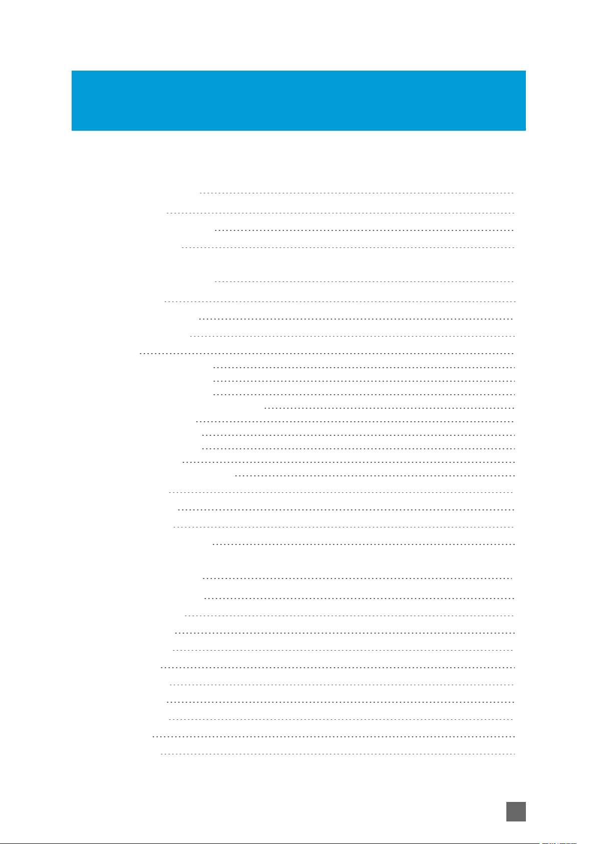
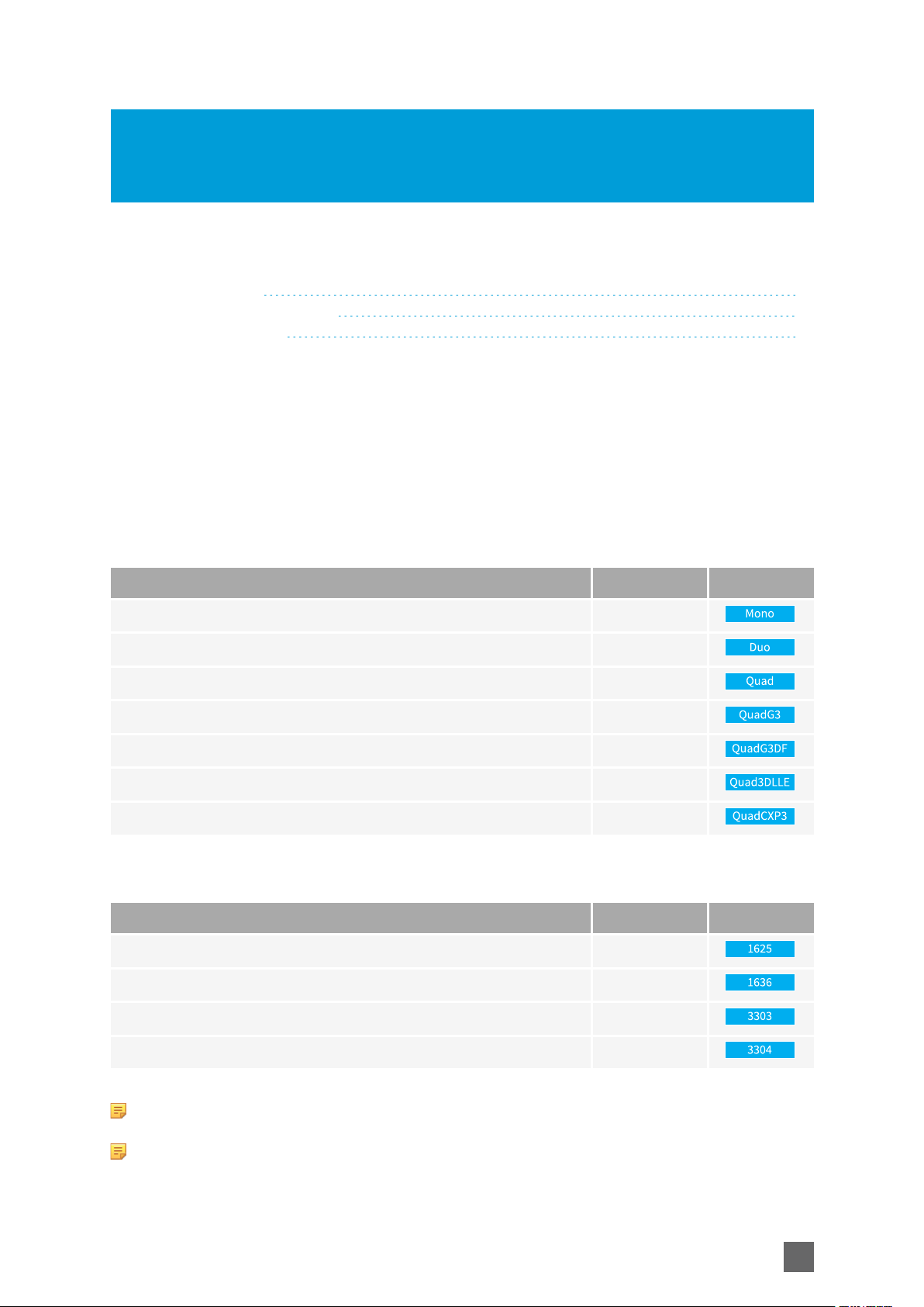
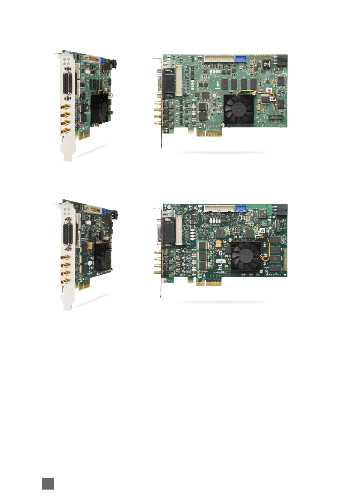
Product Pictures
Mechanical Specification Coaxlink Hardware Manual
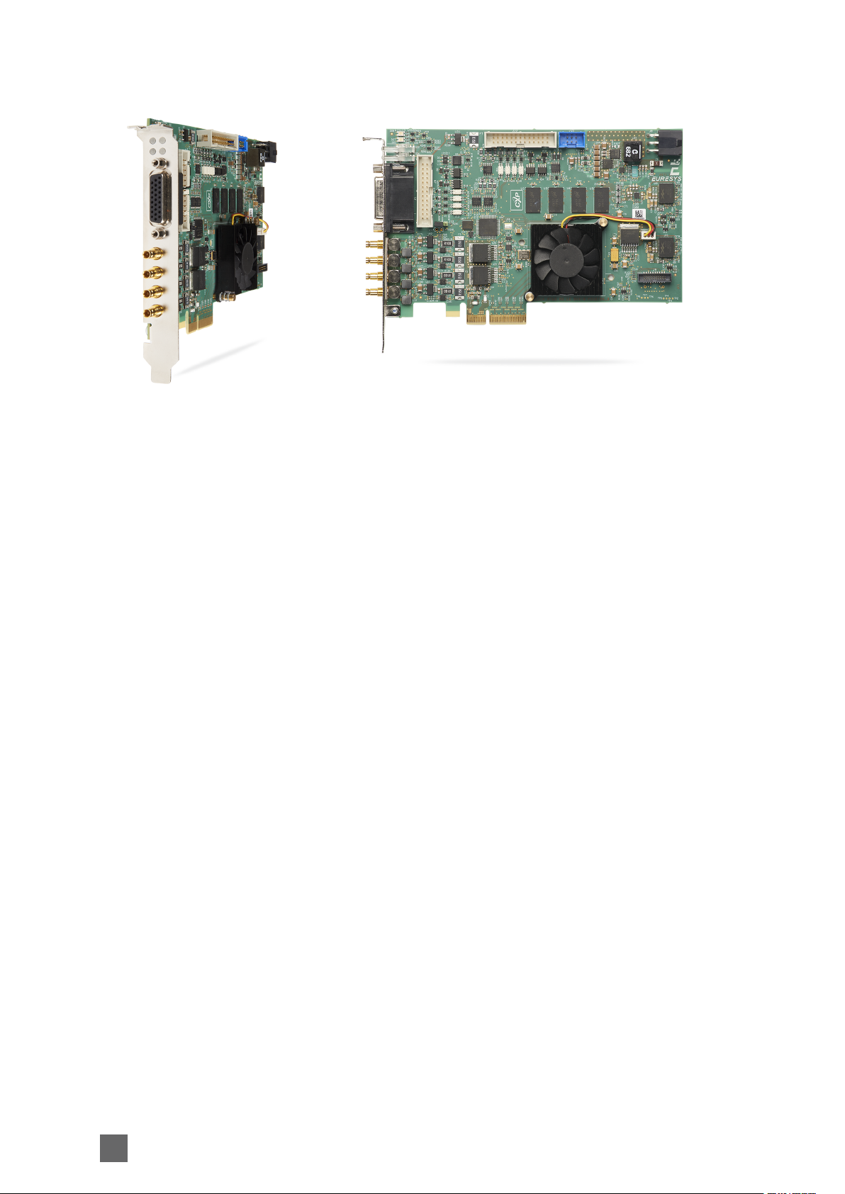
1630 Coaxlink Mono
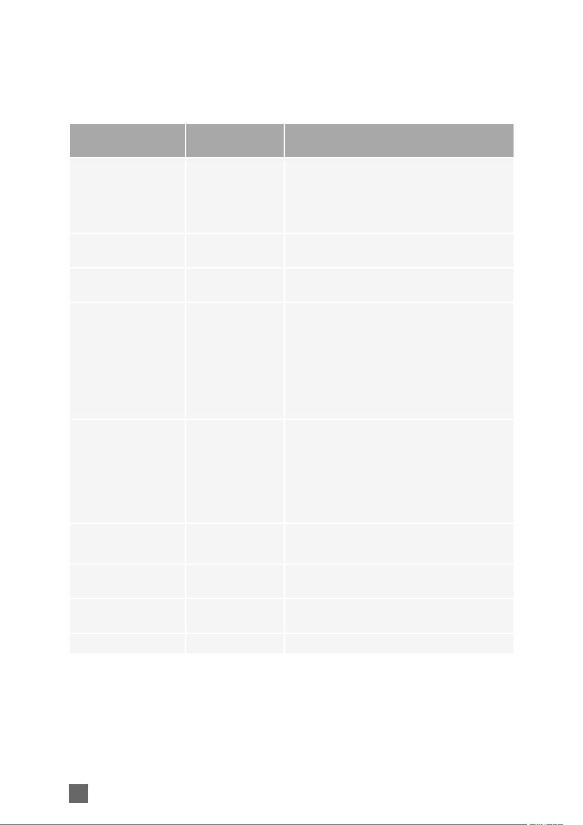
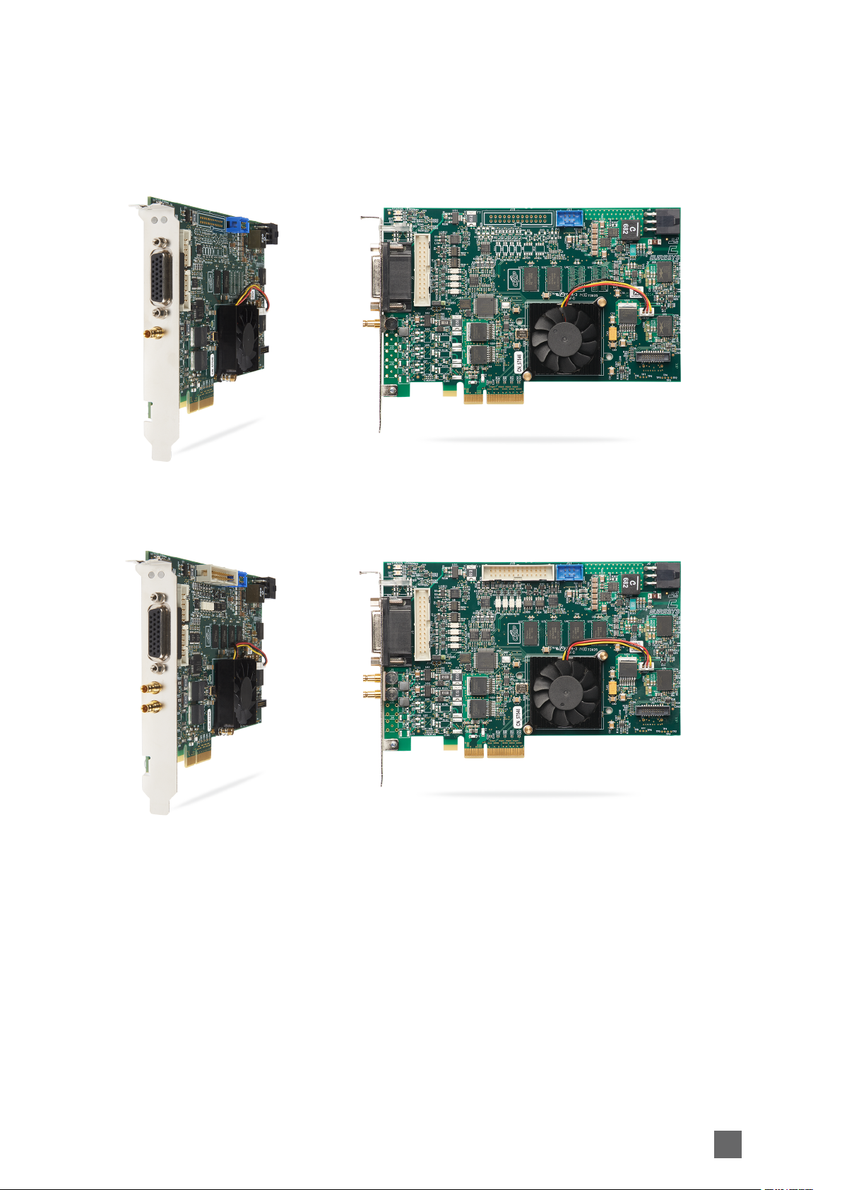
1631 Coaxlink Duo
9
Coaxlink Hardware Manual Mechanical Specification
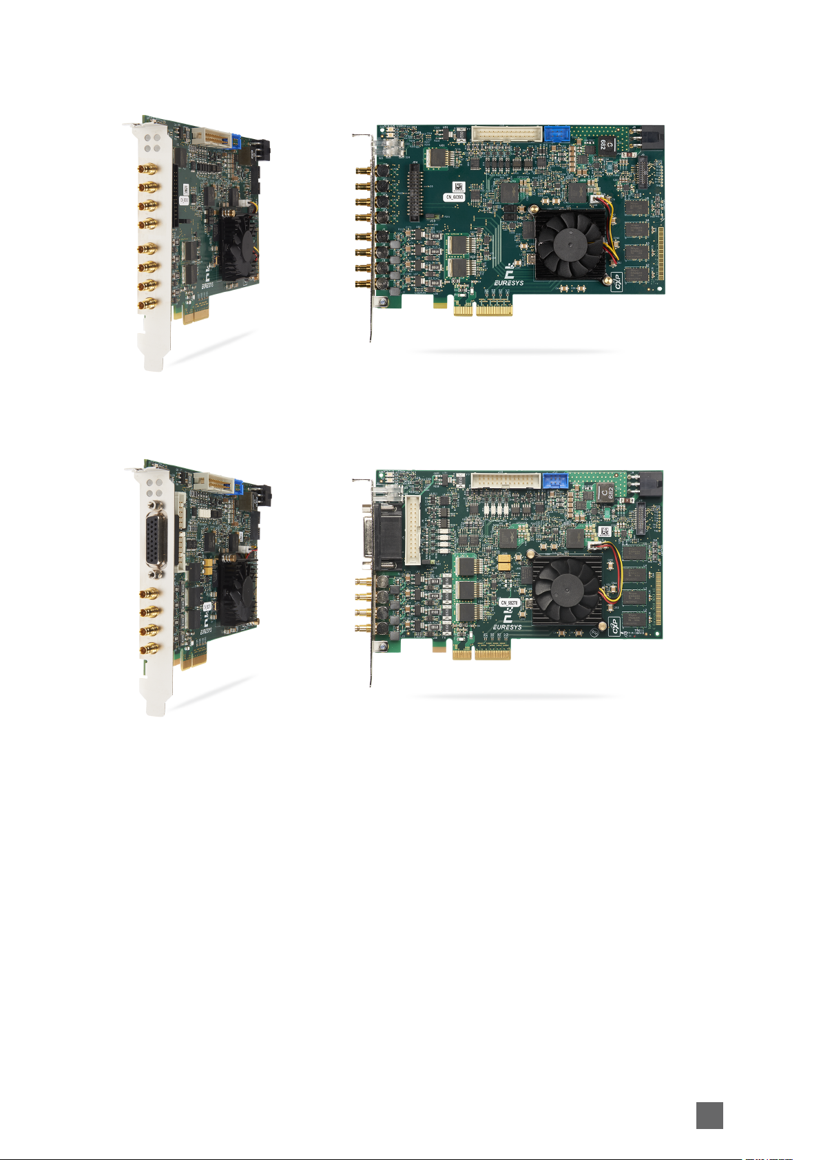
1632 Coaxlink Quad
10
1633 Coaxlink Quad G3
Mechanical Specification Coaxlink Hardware Manual
1635 Coaxlink Quad G3 DF
1637 Coaxlink Quad 3D-LLE
11
Coaxlink Hardware Manual Mechanical Specification
1638 Coaxlink Quad CXP-3
12
Mechanical Specification Coaxlink Hardware Manual
Physical Characteristics
Dimensions and weight
Product Length Height Weight
1630 Coaxlink Mono 167.65 mm, 6.6 in 111.15 mm, 4.38 in 150 g, 5.29 oz
1631 Coaxlink Duo 167.65 mm, 6.6 in 111.15 mm, 4.38 in 160 g, 5.64 oz
1632 Coaxlink Quad 167.65 mm, 6.6 in 111.15 mm, 4.38 in 170 g, 6.00 oz
1633 Coaxlink Quad G3 167.65 mm, 6.6 in 111.15 mm, 4.38 in 180 g, 6.35 oz
1635 Coaxlink Quad G3 DF 167.65 mm, 6.6 in 111.15 mm, 4.38 in 186 g, 6.56 oz
1637 Coaxlink Quad 3D-LLE 167.65 mm, 6.6 in 111.15 mm, 4.38 in 180 g, 6.35 oz
1638 Coaxlink Quad CXP-3 167.65 mm, 6.6 in 111.15 mm, 4.38 in 170 g, 6.00 oz
13
Coaxlink Hardware Manual Mechanical Specification
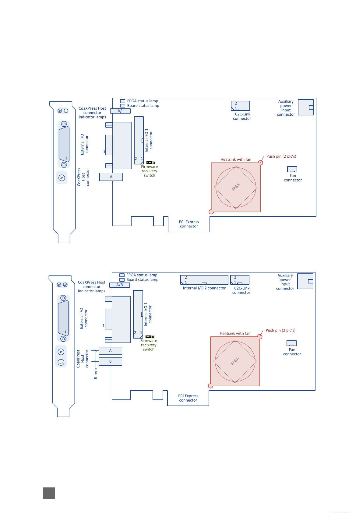
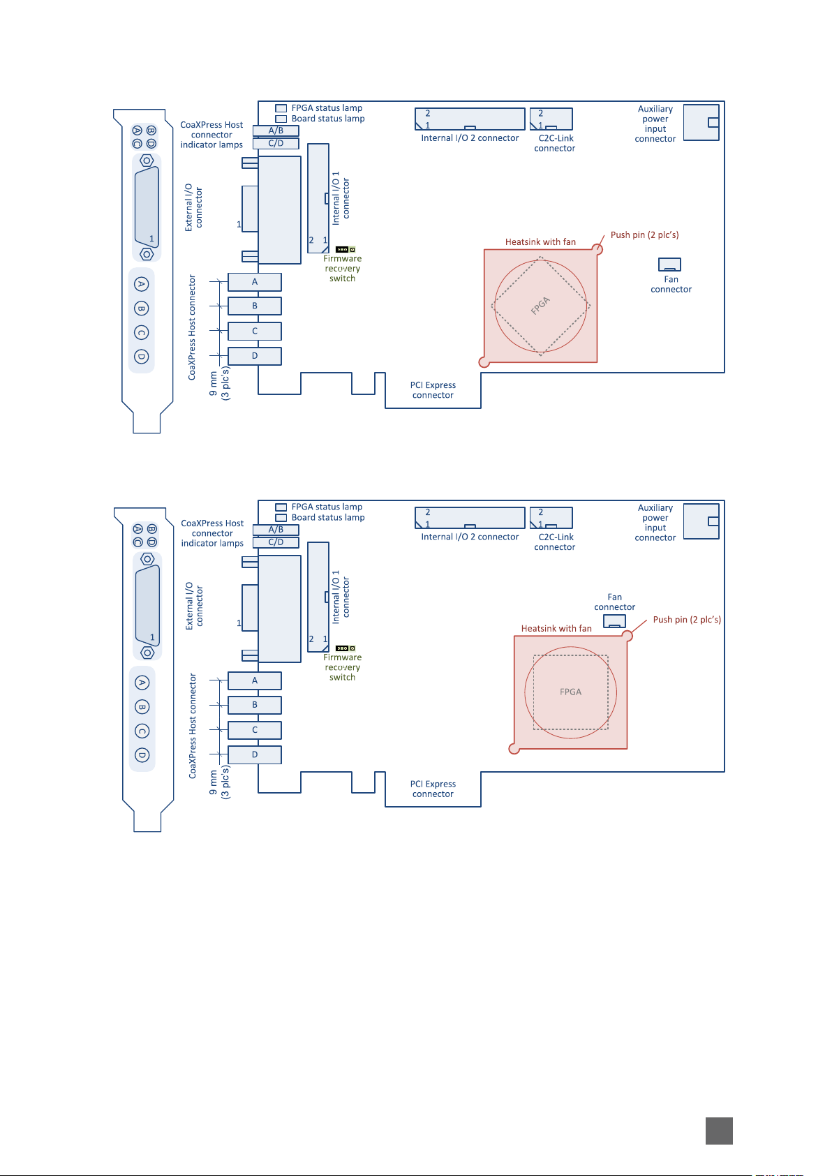
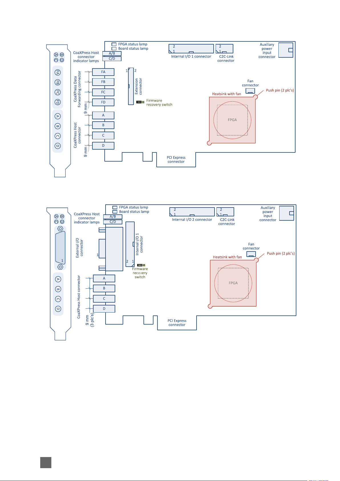
Components Location
Location drawings of connectors, lamps, switches and main components
1630 Coaxlink Mono
1631 Coaxlink Duo
14
Mechanical Specification Coaxlink Hardware Manual
1632 Coaxlink Quad
1633 Coaxlink Quad G3
15
Coaxlink Hardware Manual Mechanical Specification
1635 Coaxlink Quad G3 DF
1637 Coaxlink Quad 3D-LLE
16
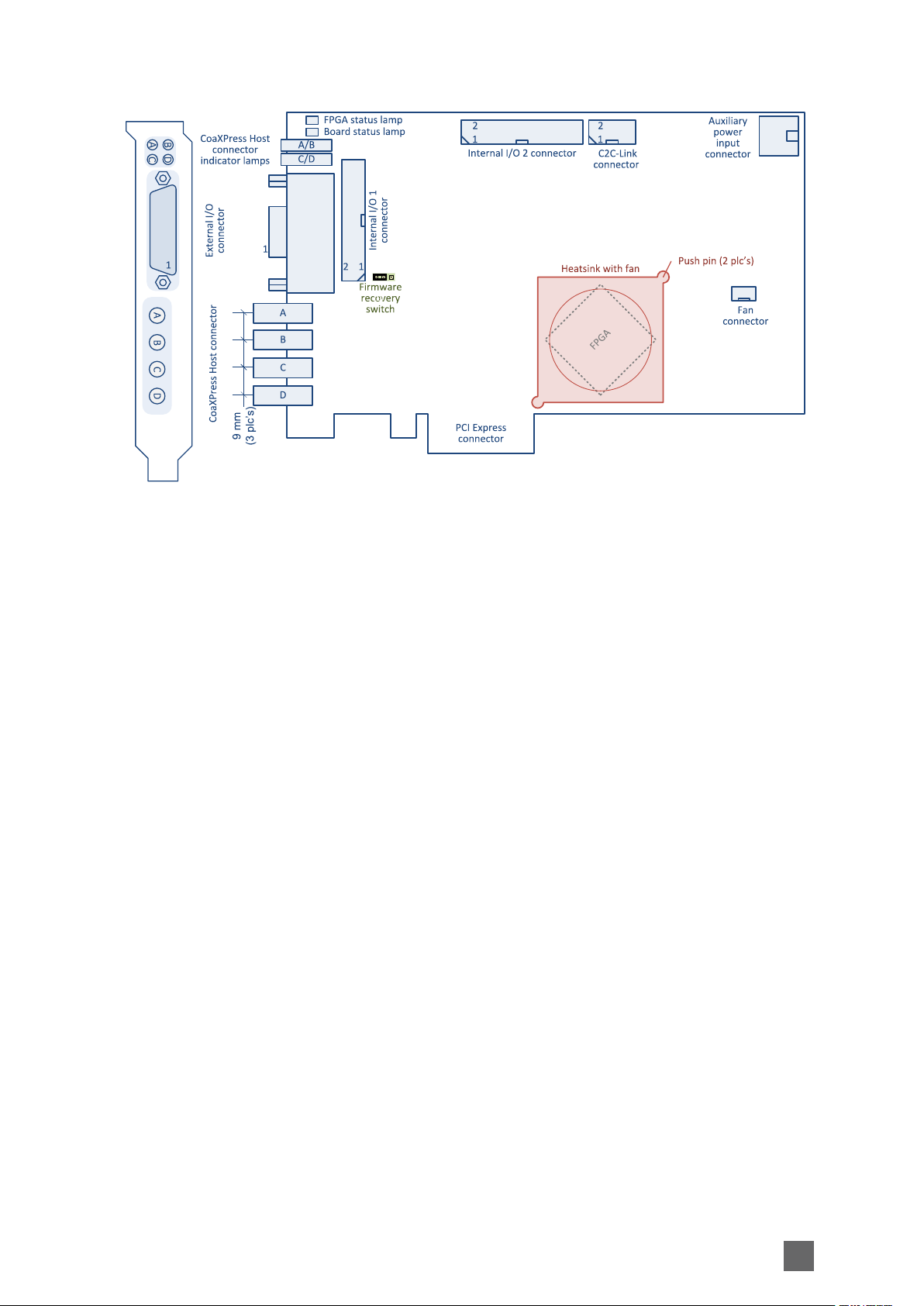
Mechanical Specification Coaxlink Hardware Manual
1638 Coaxlink Quad CXP-3
17

Coaxlink Hardware Manual Mechanical Specification
Connectors
CoaXPress Host Connector 19
CoaXPress Host Connector 20
CoaXPress Host Connector 21
CoaXPress Data Forwarding Connector 22
External I/O Connector 23
Internal I/O 1 Connector 25
Internal I/O 2 Connector 27
C2C-Link Connector 29
Auxiliary Power Input Connector 30
18
Mechanical Specification Coaxlink Hardware Manual
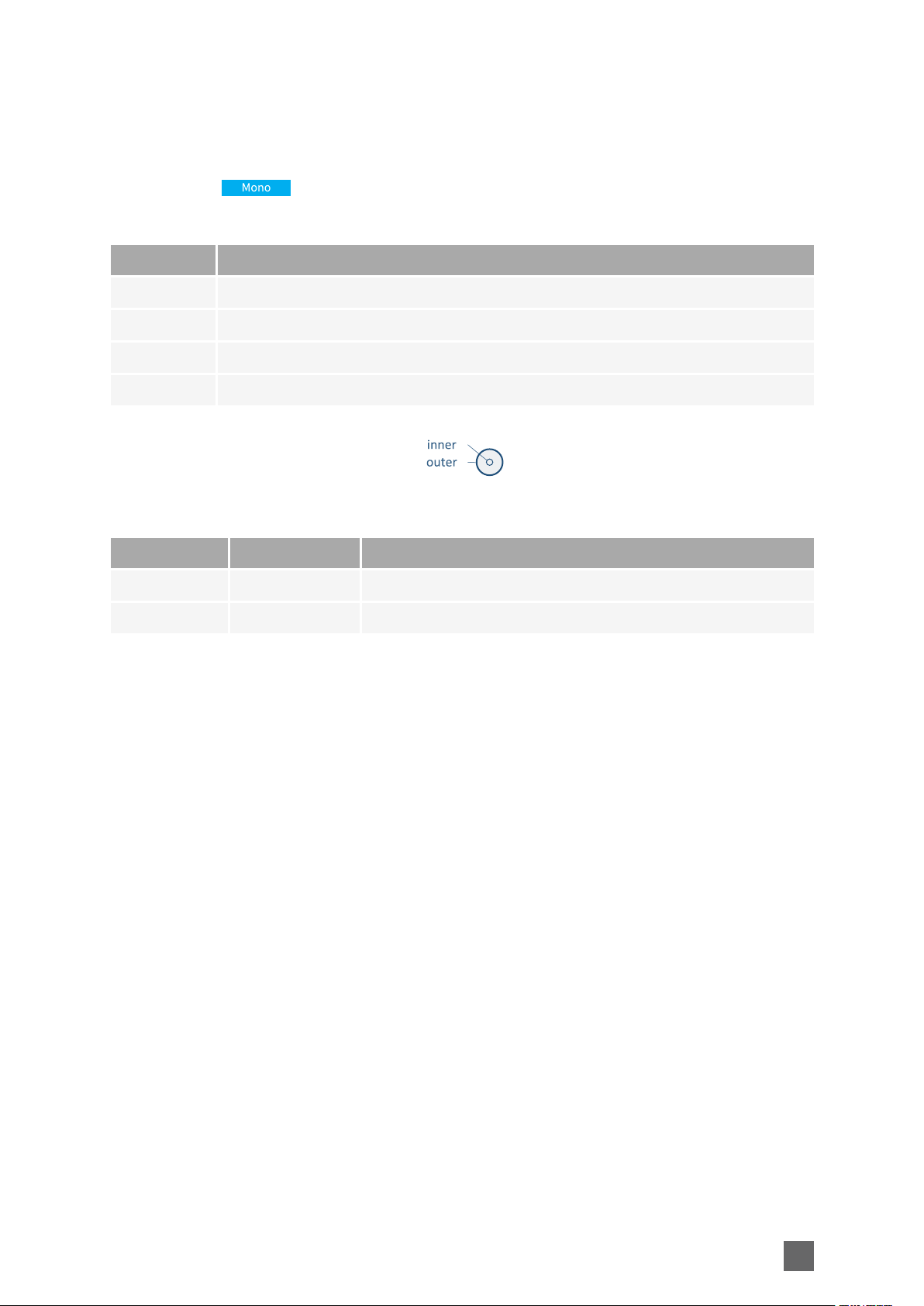
CoaXPress Host Connector
Applies to:
Connector description
Property Value
Name CoaXPress Host
Type DIN 1.0/2.3 75 Ohms coaxial female receptacle
Location Card bracket
Usage CoaXPress Host Interface CoaXPress Data Forwarding Interface
Pin assignments
Pin Signal Usage
Inner CXP_A CoaXPress Host Connection A
Outer GND Ground
19
Coaxlink Hardware Manual Mechanical Specification
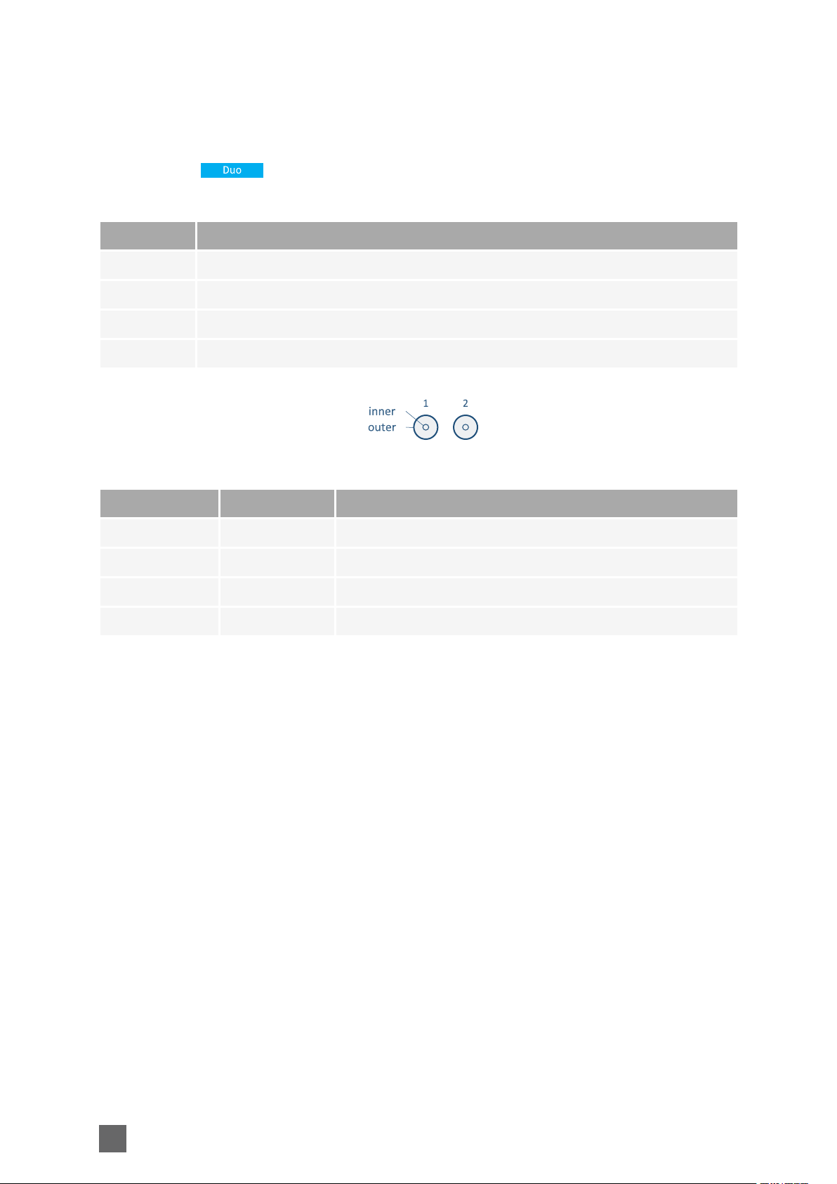
CoaXPress Host Connector
Applies to:
Connector description
Property Value
Name CoaXPress Host
Type 2 x DIN 1.0/2.3 75 Ohms coaxial receptacles
Location Card bracket
Usage CoaXPress Host Interface CoaXPress Data Forwarding Interface
Pin assignments
Pin Signal Usage
Inner1 CXP_A CoaXPress Host Connection A
Outer1 GND Ground
Inner2 CXP_B CoaXPress Host Connection B
Outer2 GND Ground
20
Mechanical Specification Coaxlink Hardware Manual
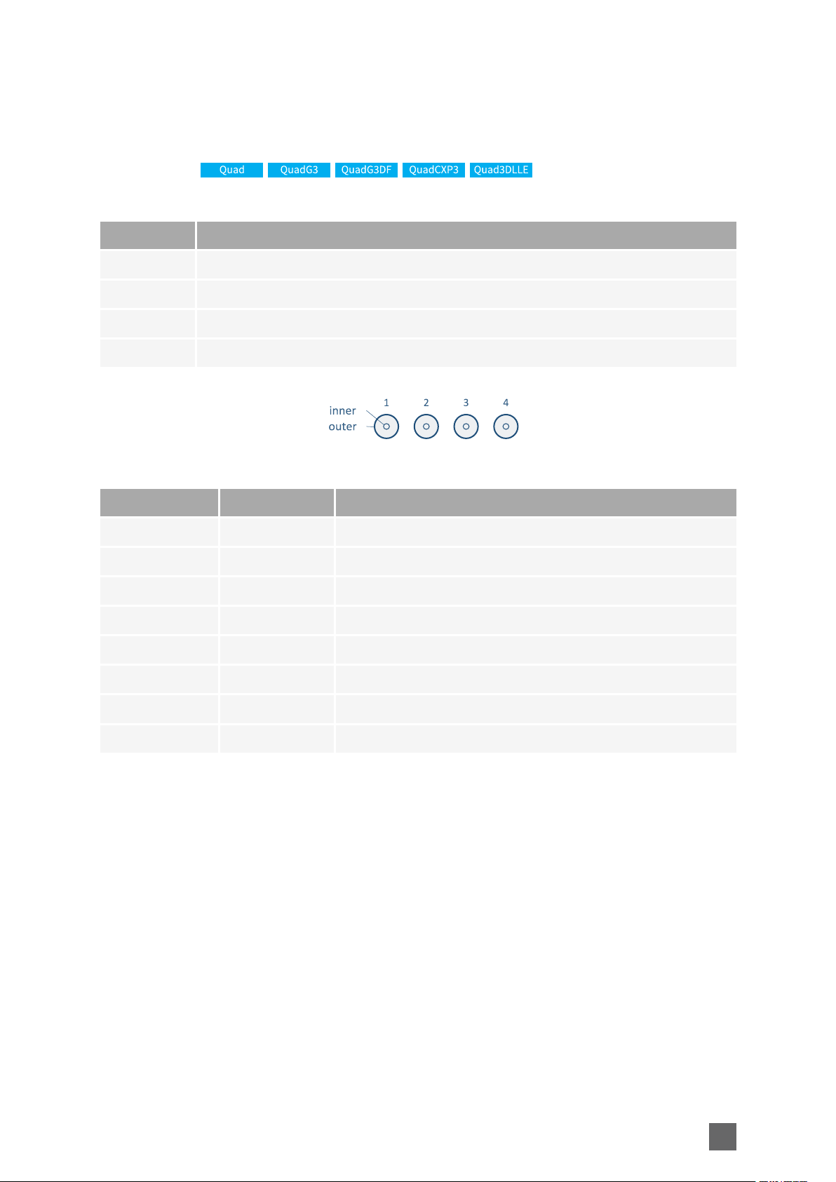
CoaXPress Host Connector
Applies to:
Connector description
Property Value
Name CoaXPress Host
Type 4 x DIN 1.0/2.3 75 Ohms coaxial receptacles
Location Card bracket
Usage CoaXPress Host Interface CoaXPress Data Forwarding Interface
Pin assignments
Pin Signal Usage
Inner1 CXP_A CoaXPress Host Connection A
Outer1 GND Ground
Inner2 CXP_B CoaXPress Host Connection B
Outer2 GND Ground
Inner3 CXP_C CoaXPress Host Connection C
Outer3 GND Ground
Inner4 CXP_D CoaXPress Host Connection D
Outer4 GND Ground
21
Coaxlink Hardware Manual Mechanical Specification
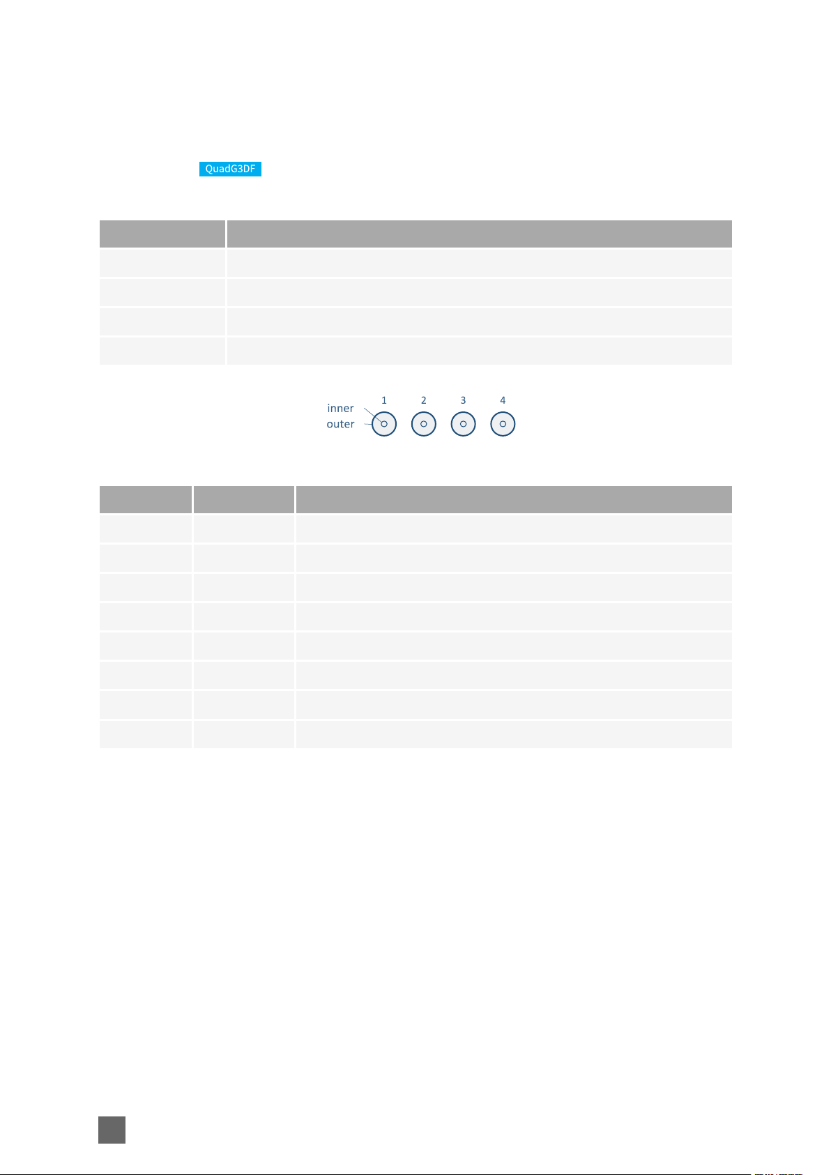
CoaXPress Data Forwarding Connector
Applies to:
Connector description
Property Value
Name CoaXPress Data Forwarding
Type 4 x DIN 1.0/2.3 75 Ohms coaxial receptacles
Location Card bracket
Usage
Pin assignments
Pin Signal Usage
Inner1 CXP_FA CoaXPress Data Forwarding Connection A
Outer1 GND Ground
Inner2 CXP_FB CoaXPress Data Forwarding Connection B
Outer2 GND Ground
Inner3 CXP_FC CoaXPress Data Forwarding Connection C
Outer3 GND Ground
Inner4 CXP_FD CoaXPress Data Forwarding Connection D
Outer4 GND Ground
22
Mechanical Specification Coaxlink Hardware Manual
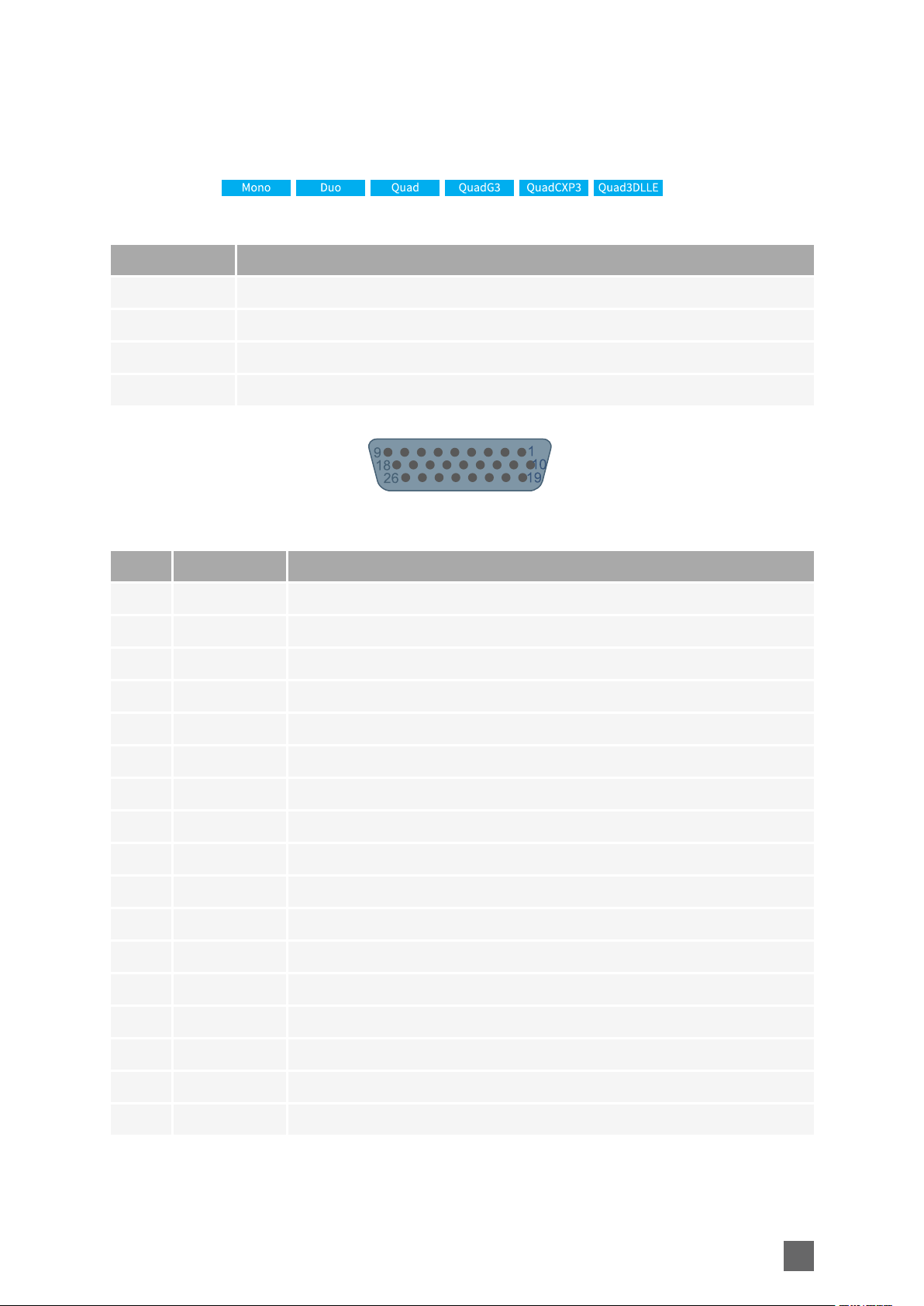
External I/O Connector
Applies to:
Connector description
Property Value
Name External I/O
Type 26-pin 3-row high-density female sub-D connector
Location Card bracket
Usage General purpose I/O and power output
Pin assignments
Pin Signal Usage
1 GND Ground
2 DIN12+ High-speed differential input #12 – Positive pole
3 IIN11+ Isolated input #11 – Positive pole
4 IIN13- Isolated input #13 – Negative pole
5 IIN14- Isolated input #14 – Negative pole
6 IOUT12- Isolated contact output #12 – Negative pole
7 GND Ground
8 Not connected
9 GND Ground
10 GND Ground
11 DIN12- High-speed differential input #12 – Negative pole
12 IIN11- Isolated input #11 – Negative pole
13 IIN12+ Isolated input #12 – Positive pole
14 IIN13+ Isolated input #13 – Positive pole
15 IIN14+ Isolated input #14 – Positive pole
16 IOUT12+ Isolated contact output #12 – Positive pole
17 TTLIO12 TTL input/output #12
23
Coaxlink Hardware Manual Mechanical Specification
Pin Signal Usage
18 GND Ground
19 DIN11- High-speed differential input #11 – Negative pole
20 DIN11+ High-speed differential input #11 – Positive pole
21 IIN12- Isolated input #12 – Negative pole
22 IOUT11- Isolated contact output #11 – Negative pole
23 IOUT11+ Isolated contact output #11 – Positive pole
24 GND Ground
25 TTLIO11 TTL input/output #11
26 +12V +12 V Power output
24
Mechanical Specification Coaxlink Hardware Manual
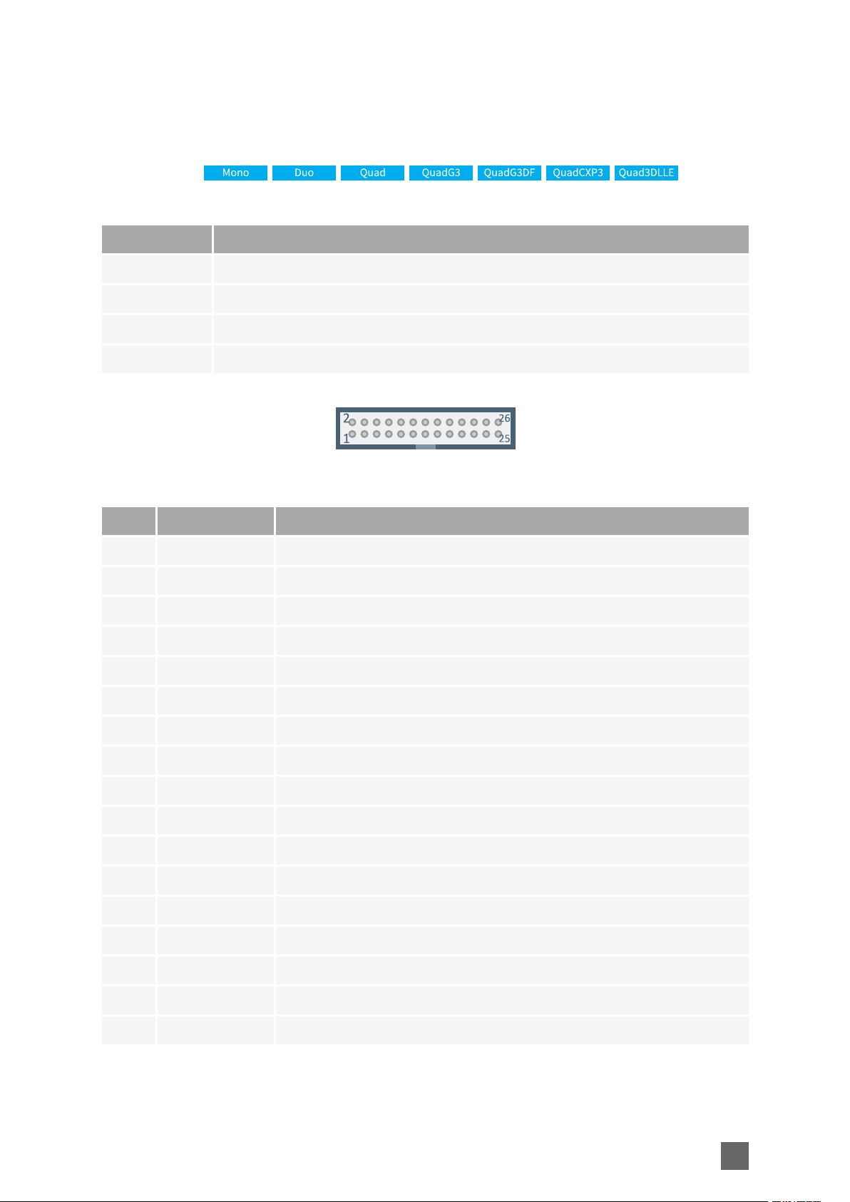
Internal I/O 1 Connector
Applies to:
Connector description
Property Value
Name Internal I/O 1
Type 26-pin dual-row 0.1" pitch pin header with shrouding
Location Printed circuit board
Usage General purpose I/O and power output
Pin assignments
Pin Signal Usage
1 GND Ground
2 GND Ground
3 DIN11+ High-speed differential input #11 – Positive pole
4 DIN11- High-speed differential input #11 – Negative pole
5 DIN12+ High-speed differential input #12 – Positive pole
6 DIN12- High-speed differential input #12 – Negative pole
7 IIN11+ Isolated input #11 – Positive pole
8 IIN11- Isolated input #11 – Negative pole
9 IIN12+ Isolated input #12 – Positive pole
10 IIN12- Isolated input #12 – Negative pole
11 IIN13+ Isolated input #13 – Positive pole
12 IIN13- Isolated input #13 – Negative pole
13 IIN14+ Isolated input #14 – Positive pole
14 IIN14- Isolated input #14 – Negative pole
15 IOUT11+ Isolated contact output #11 – Positive pole
16 IOUT11- Isolated contact output #11 – Negative pole
17 IOUT12+ Isolated contact output #12 – Positive pole
25

Coaxlink Hardware Manual Mechanical Specification
Pin Signal Usage
18 IOUT12- Isolated contact output #12 – Negative pole
19 TTLIO11 TTL input/output #11
20 GND Ground
21 TTLIO12 TTL input/output #12
22 GND Ground
23 Not connected
24 GND Ground
25 +12V +12 V Power output
26 +12V_RTN Ground
26

Mechanical Specification Coaxlink Hardware Manual
Internal I/O 2 Connector
Applies to:
Connector description
Property Value
Name Internal I/O 2
Type 26-pin dual-row 0.1" pitch pin header with shrouding
Location Printed circuit board
Usage General purpose I/O and power output
Pin assignments
Pin Signal Usage
1 GND Ground
2 GND Ground
3 DIN21+ High-speed differential input #21 – Positive pole
4 DIN21- High-speed differential input #21 – Negative pole
5 DIN22+ High-speed differential input #22 – Positive pole
6 DIN22- High-speed differential input #22 – Negative pole
7 IIN21+ Isolated input #21 – Positive pole
8 IIN21- Isolated input #21 – Negative pole
9 IIN22+ Isolated input #22 – Positive pole
10 IIN22- Isolated input #22 – Negative pole
11 IIN23+ Isolated input #23 – Positive pole
12 IIN23- Isolated input #23 – Negative pole
13 IIN24+ Isolated input #24 – Positive pole
14 IIN24- Isolated input #24 – Negative pole
15 IOUT21+ Isolated contact output #21 – Positive pole
16 IOUT21- Isolated contact output #21 – Negative pole
17 IOUT22+ Isolated contact output #22 – Positive pole
27

Coaxlink Hardware Manual Mechanical Specification
Pin Signal Usage
18 IOUT22- Isolated contact output #22 – Negative pole
19 TTLIO21 TTL input/output #21
20 GND Ground
21 TTLIO22 TTL input/output #22
22 GND Ground
23 Not connected
24 GND Ground
25 +12V +12 V Power output
26 +12V_RTN Ground
28

Mechanical Specification Coaxlink Hardware Manual
C2C-Link Connector
Applies to:
Connector description
Property Value
Name C2C-Link
Type 6-pin dual-row 0.1" pitch pin header with shrouding
Location Printed circuit board
Usage Card-to-card link
Pin assignments
Pin Signal Usage
1 GND Ground
2 CSync1 Card-to-card synchronization bus – Signal 1
3 GND Ground
4 CSync2 Card-to-card synchronization bus – Signal 2
5 GND Ground
6 CSync3 Card-to-card synchronization bus – Signal 3
29

Coaxlink Hardware Manual Mechanical Specification
Auxiliary Power Input Connector
Applies to:
Connector description
Property Value
Name Auxiliary Power Input
Type 6-pin PCI Express x16 Graphics 150W ATX power socket connector
Location Printed circuit board
Usage DC power input for PoCXP and GPIO power output
Pin assignments
Pin Signal Usage
1 +12VIN Auxiliary +12 V input
2 +12VIN Auxiliary +12 V input
3 +12VIN Auxiliary +12 V input
4 GND Ground
5 SenseIN Power source presence detection
6 GND Ground
30

Mechanical Specification Coaxlink Hardware Manual
CoaXPress Lamps
Each connector of the CoaXPress Host Interface is associated with a CoaXPress Host Indicator
Lamp that indicates the state of the CoaXPress Link connection.
CoaXPress Host Connector Indicator Lamps State
Symbol Lamp State Meaning
Off The Coaxlink card is not powered
Solid orange System booting
The connection detection is in progress; PoCXP is active.
Fast flash alternate
green / orange
This state is shown for a minimum of 1s even if the
connection detection is faster
The connection detection is in progress; PoCXP is off.
Fast flash orange
Solid red The PoCXP over-current protection has tripped.
Solid green
Slow pulse orange
Fast flash green.
Flashing Lamp States Timing Definitions
Indication Timing
Fast flash 12.5Hz @25% duty cycle: 20 ms on, 60 ms off
Fast flash alternate (color
1/color 2)
12.5Hz @25% duty cycle: 20 ms on (color 1), 60 ms off, 20 ms
on (color 2), 60 ms off
This state is shown for a minimum of 1s even if the
connection detection is faster
The Device to Host connection is established, but no
data being transferred
The Device to Host connection is established, but the
Host is waiting for a trigger.
The Device to Host connection is established and image
data is being transferred
Slow flash 0.5Hz @50% duty cycle: 1 second on, 1 second off
Slow pulse (red | orange) 1Hz @ 20% duty cycle: 200ms on, 800ms off
31

Coaxlink Hardware Manual Mechanical Specification
Board Status Lamp
Board status lamp indicator states
Lamp
state
Off
Solid
green
Solid
red
Symbol Meaning
No power.
The board is not powered or the power distribution network is not
functional.
Board status OK.
The main power distribution network is operational and the FPGA start-up
procedure has successfully completed.
Board status NOK.
Possible causes are:
▶ There is no power delivered on the +12 V rail of the PCI Express
connector slot
▶ The FPGA start-up procedure is not completed. The normal completion
time is around 100 milliseconds.
▶ At least one power converter of the main power distribution network is
unable to operate properly. This might be caused by excessive
temperature due to inadequate board cooling, accidental short-circuits
having blown one (or more) protection fuses, inappropriate supply
voltages, etc.
32

FPGA Status Lamp
FPGA status lamp indicator states
Mechanical Specification Coaxlink Hardware Manual
Lamp
state
Off Board not powered.
Solid
green
Solid
red
Symbol Meaning
FPGA status OK.
All the FPGA clock networks and the DDR memory are operating normally.
FPGA status NOK.
Possible causes are:
▶ At least one FPGA clock network is not operating normally. This might
be caused by excessive jitter on external clock signals of the CoaXPress or
the PCI Express interfaces.
▶ The DDR memory controller has not been able to successfully perform
the calibration procedure.
33

Coaxlink Hardware Manual Mechanical Specification
Firmware Recovery Switch
Jumper positions
Jumper
position
The recovery mode must be used only in case of emergency situations: i.e. when the latest
uploaded firmware is not functional and the card is no more detected by the Host PC.
Meaning
Normal mode.(Factory default)
At next power on, the FPGA will boot with the latest uploaded firmware.
Recovery mode.
At next power on, the FPGA will boot with the last but one uploaded
firmware.
34

Electrical Specification Coaxlink Hardware Manual
Electrical Specification
Electrical specification of the product(s) including: electrical characteristics of all the
input/output ports, description of the power distribution, power requirements, etc.
CoaXPress Host Interface 36
PCI Express Interface 39
Power Distribution 42
PCI Express Power 47
Auxiliary Power 50
I/O Power Output 51
Differential Input 52
TTL Input/Output 54
Isolated Input 56
Isolated Output 58
35

Coaxlink Hardware Manual Electrical Specification
CoaXPress Host Interface
Electrical specification of the CoaXPress Host interface
Each connection of the CoaXPress Host interface implements a Host Transceiver (HT) and a
Power Transmitting Unit (PTU).
CXP-6 HOST TRANSCEIVER
Applies to:
The Host transceiver implements a high-speed cable receiver and a low-speed cable driver for
CXP-6 speeds.
It fulfills the electrical specification of the CoaXPress 1.1 standard. Namely:
▶ The cable receiver requirements for the high-speed connection described in Table 2 of the
Annex B of the CoaXPress Standard 1.1
▶ The cable driver requirements for the low-speed connection described in Table 3 of the
Annex B of the CoaXPress Standard 1.1
Host Transceiver Specification
Parameter Conditions Min. Typ. Max. Unit
High-speed connection bit rate 1.25 6.25 GT/s
Low-speed connection bit rate 20.833 MT/s
BELDEN 1694 @ 1.25 GT/s 130 m
BELDEN 1694 @ 2.5 GT/s 110 m
Max. cable length
CXP-3 HOST TRANSCEIVER
Applies to:
BELDEN 1694 @ 3.125 GT/s 100 m
BELDEN 1694 @ 5 GT/s 60 m
BELDEN 1694 @ 6.25 GT/s 40 m
The Host transceiver implements a high-speed cable receiver and a low-speed cable driver for
CXP-3 speeds.
It fulfills the electrical specification of the CoaXPress 1.1 standard. Namely:
36

Electrical Specification Coaxlink Hardware Manual
▶ The cable receiver requirements for the high-speed connection described in Table 2 of the
Annex B of the CoaXPress Standard 1.1
▶ The cable driver requirements for the low-speed connection described in Table 3 of the
Annex B of the CoaXPress Standard 1.1
Host Transceiver Specification
Parameter Conditions Min. Typ. Max. Unit
High-speed connection bit rate 1.25 3.125 GT/s
Low-speed connection bit rate 20.833 MT/s
BELDEN 1694 @ 1.25 GT/s 130 m
Max. cable length
BELDEN 1694 @ 2.5 GT/s 110 m
BELDEN 1694 @ 3.125 GT/s 100 m
POWER TRANSMITTING UNIT
The Power Transmitting Unit implements Power over CoaXPress (PoCXP) as specified in section 7
of the CoaXPress Standard 1.1.
If fulfills all the requirements for a Host; namely:
▶ Over-current protection (OCP)
▶ PoCXP CoaXPress Device detection
In addition: it provides the user with an AUTO/OFF control:
▶ Setting the control to AUTO initiates a new PoCXP device detection; the power will be
applied only if the detection succeeds
▶ Setting the control to OFF forces the PTU to disconnect. The control is OFF after power on,
and, if providing power to the camera is required, has to be set to AUTO by the application.
Power Transmitting Unit Specification
Parameter Min. Typ. Max. Unit
DC output voltage 22 24 26 V
Available output power 17 W
OCP holding current 790 mA
OCP nominal trip current 5 A
PoCXP Device detection sensing current 550 1,000 µA
37

Coaxlink Hardware Manual Electrical Specification
The above specification applies over the whole operating temperature range of the Coaxlink
card.
38

Electrical Specification Coaxlink Hardware Manual
PCI Express Interface
Specification of the PCI Express Interface
The PCI Express Interface implements a PCIe end-point interface and provides electrical power
to the Coaxlink card.
PCI Express end-point type per product
Product Type
1630 Coaxlink Mono 4-lane Rev 2.0
1631 Coaxlink Duo 4-lane Rev 2.0
1632 Coaxlink Quad 4-lane Rev 2.0
1633 Coaxlink Quad G3 4-lane Rev 3.0
1635 Coaxlink Quad G3 DF 4-lane Rev 3.0
1637 Coaxlink Quad 3D-LLE 4-lane Rev 2.0
1638 Coaxlink Quad CXP-3 4-lane Rev 2.0
39

Coaxlink Hardware Manual Electrical Specification
4-LANE REV 3.0 PCIE END-POINT
Applies to:
The 4-lane Rev 3.0 PCIe end-point:
▶ complies with Revision 3.0 of the PCI Express Card Electromechanical specification.
▶ supports 1-lane, 2-lane, and 4-lane link width
▶ supports PCIe Rev 2.0 link speed (5.0 GT/s with 8b/10b coding)
▶ supports PCIe Rev 3.0 link speed (8.0 GT/s with 128b/130b coding)
▶ supports payload size up to 512 bytes
▶ offers the optimal performance when it is configured for 4-lane PCIe Rev 3.0 link speed (8
GT/s)
▶ doesn't support the PCIe Rev 1.0 link speed (2.5 GT/s with 8b/10b coding)
4-lane Rev 3.0 PCIe end-point to PC memory data transfer performance
Parameter Conditions Min. Typ. Max. Unit
4-lane @ 8 GT/s (PCIe Rev 3.0) 3,350 MB/s
4-lane @ 5 GT/s (PCIe Rev 2.0) 1,700 MB/s
Sustainable output data rate
2-lane @ 8 GT/s (PCIe Rev 3.0) 1,700 MB/s
2-lane @ 5 GT/s (PCIe Rev 2.0) 800 MB/s
1-lane @ 8 GT/s (PCIe Rev 3.0) 800 MB/s
40

Electrical Specification Coaxlink Hardware Manual
4-LANE REV 2.0 PCIE END-POINT
Applies to:
The 4-lane Rev 2.0 PCIe end-point:
▶ complies with Revision 2.0 of the PCI Express Card Electromechanical specification.
▶ supports 1-lane, 2-lane, and 4-lane link width
▶ supports PCIe Rev 1.0 link speed (2.5 GT/s with 8b/10b coding)
▶ supports PCIe Rev 2.0 link speed (5.0 GT/s with 8b/10b coding)
▶ supports payload size up to 512 bytes
▶ offers the optimal performance when it is configured for 4-lane PCIe Rev 2.0 link speed (5
GT/s)
4-lane Rev 3.0 PCIe end-point to PC memory data transfer performance
Parameter Conditions Min. Typ. Max. Unit
Sustainable output data rate
4-lane @ 5 GT/s (PCIe Rev 2.0) 1,700 MB/s
4-lane @ 2.5 GT/s (PCIe Rev
1.0)
800 MB/s
MB/s
2-lane @ 5 GT/s (PCIe Rev 2.0) 800
41

Coaxlink Hardware Manual Electrical Specification
Power Distribution
Description of the power distribution
POWER DISTRIBUTION SCHEME
The power distribution scheme of a Coaxlink PCIe card has two distinct distribution networks:
▶ The main power distribution network
▶ The auxiliary power distribution network
1630 Coaxlink Mono power distribution scheme
42

Electrical Specification Coaxlink Hardware Manual
1631 Coaxlink Duo power distribution scheme
1632 Coaxlink Quad power distribution scheme
1633 Coaxlink Quad G3 power distribution scheme
43

Coaxlink Hardware Manual Electrical Specification
1635 Coaxlink Quad G3 DF power distribution scheme
44
1637 Coaxlink Quad 3D-LLE power distribution scheme

Electrical Specification Coaxlink Hardware Manual
1638 Coaxlink Quad CXP-3 power distribution scheme
The fuses are not serviceable! When blown, the card must be returned to the factory.
PTCs and electronic fuses are self-resettable fuses.
The Coaxlink card can be operated without applying power to the auxiliary power
distribution network.
MAIN POWER DISTRIBUTION NETWORK
The main power distribution network delivers power to all the on-board electronic devices
including FPGA, memory chips, CoaXPress transceivers, I/O drivers and receivers, fan motor.
The network is fed by the Host PC motherboard through the +3.3 V and the +12 V power rails of
the PCI Express slot connector. Protection fuses inserted at the input side of each power rail
prevent potential fire hazards.
The board status LED lamp reflects the global status of all the power converters of the main
distribution network.
45

Coaxlink Hardware Manual Electrical Specification
AUXILIARY POWER DISTRIBUTION NETWORK
The auxiliary power distribution network delivers power to the external devices including:
▶ CoaXPress cameras using the PoCXP capability available on all connections of the CoaXPress
Host connector
▶ System devices using the +12 V power output available on all I/O connectors
The network is fed by a 12 V external power supply attached to the auxiliary power input
connector using a power cable terminated by a 6-pin PEG plug connector. A protection fuse
inserted at the input side prevents potential fire hazards.
A 24-volt DC power converter provides power to each camera connection through a PoCXP
transmitter unit. Each PoCXP transmitter unit implements an electronic fuse/switch. A PTC
inserted at the input of each transmitter unit prevents potential fire hazards.
The +12 V power is distributed from a common electronic fuse to all the I/O connectors. A PTC
inserted at the input of prevents potential fire hazards.
The "CoaXPress Lamps" on page31 reflect the state of each CoaXPress host connection.
The following auxiliary power distribution network status are reported to the application:
▶ Presence of a PEG cable and a PEG compliant power supply
▶ Valid 12 V voltage measured after the 12 A fuse.
▶ 24 V DC power converter status
▶ Output current and output voltage of each PoCXP transmitter
46

Electrical Specification Coaxlink Hardware Manual
PCI Express Power
PCI Express power requirements specification
1630 COAXLINK MONO
Parameter Min. Typ. Max. Units
+3.3 V voltage 3.0 3.3 3.6 V
+12 V voltage 11.0 12.0 13.0 V
+3.3 V power 2.1 W
+12 V power 7.2 W
Total power 9.3 W
1631 COAXLINK DUO
Parameter Min. Typ. Max. Units
+3.3 V voltage 3.0 3.3 3.6 V
+12 V voltage 11.0 12.0 13.0 V
+3.3 V power 2.7 W
+12 V power 8.7 W
Total power 11.4 W
1632 COAXLINK QUAD
Parameter Min. Typ. Max. Units
+3.3 V voltage 3.0 3.3 3.6 V
+12 V voltage 11.0 12.0 13.0 V
+3.3 V power 2.5 W
+12 V power 9.6 W
Total power 12.1 W
47

Coaxlink Hardware Manual Electrical Specification
1633 COAXLINK QUAD G3
Parameter Min. Typ. Max. Units
+3.3 V voltage 3.0 3.3 3.6 V
+12 V voltage 11.0 12.0 13.0 V
+3.3 V power 3.8 W
+12 V power 13 W
Total power 16.8 W
1635 COAXLINK QUAD G3 DF
Parameter Min. Typ. Max. Units
+3.3 V voltage 3.0 3.3 3.6 V
+12 V voltage 11.0 12.0 13.0 V
+3.3 V power 3.8 W
+12 V power 13 W
Total power 16.8 W
1637 COAXLINK QUAD 3D-LLE
Parameter Min. Typ. Max. Units
+3.3 V voltage 3.0 3.3 3.6 V
+12 V voltage 11.0 12.0 13.0 V
+3.3 V power 3.8 W
+12 V power 13 W
Total power 16.8 W
1638 COAXLINK QUAD CXP-3
Parameter Min. Typ. Max. Units
+3.3 V voltage 3.0 3.3 3.6 V
+12 V voltage 11.0 12.0 13.0 V
+3.3 V power TBD W
48

Electrical Specification Coaxlink Hardware Manual
Parameter Min. Typ. Max. Units
+12 V power TBD W
Total power TBD W
The typical power values were measured under the following conditions:
▶ Acquiring image data using all CoaXPress Host Interface connections operating at their
maximum speed
▶ Delivering image data on the PCI Express configured for the largest link width and the highest
link speed
▶ Operating @25°C [77 °F] ambient temperature and nominal supply voltages
49

Coaxlink Hardware Manual Electrical Specification
Auxiliary Power
Applies to:
Specification of the auxiliary power input
Parameter Conditions Min. Typ. Max. Units
DC input voltage 11 12 13 V
DC input power for I/O 12W I/O output power 0 12 W
17W total PoCXP output power 19 W
DC input power for PoCXP
[Power Converter Specification]
Parameter Conditions Min. Typ. Max. Units
DC input voltage 11 12 13 V
DC output voltage 23 24 25 V
Power conversion efficiency 70W total PoCXP output power 92.5 %
The sense input of the PEG connector is intended for power source cable presence detection.
It should be grounded at the power supply level.
The power rating of the power source is application dependent.
34W total PoCXP output power 37 W
68W total PoCXP output power 74 W
50

Electrical Specification Coaxlink Hardware Manual
I/O Power Output
Specification of the +12V power output of the I/O connector
A non-isolated +12 V power output is available on every I/O connector.
The power originates from an external 12 V power supply plugged into the Auxiliary Power Input
connector. It is distributed from a common electronic fuse to all the I/O connectors.
The electronic fuse provides the following protections:
▶ Limits the inrush current during power on sequence
▶ Protects the Coaxlink card and the power source against overload
▶ Protects the Coaxlink card the power source against short-circuits.
The sum of the load currents drawn from all the 12 V outputs of the I/O connectors must be
lower or equal to the specified maximum output current.
I/O +12 V power output specification
Parameter Conditions Min. Typ. Max. Units
Aggregated output current
Voltage drop across the electronic
fuse
The above specification applies over the whole operating temperature range of the Coaxlink
card.
Operating temperature
range
Max. output current 0.2 V
1.0 A
51

Coaxlink Hardware Manual Electrical Specification
Differential Input
Specification of the differential GPIO input ports
Differential Input Simplified Schematic
The receiver complies with the ANSI/TIA/EIA-422B specification.
DC CHARACTERISTICS
Parameter Conditions Min. Typ. Max. Units
Common mode voltage -7 +7 V
Differential sensitivity 200 mV
Input impedance 120 Ohm
Human Body Model (HBM) 15 kV
ESD protection
AC CHARACTERISTICS
Parameter Min. Typ. Max. Units
Pulse width 100 ns
Contact discharge 8 kV
Air gap discharge 15 kV
Pulse rate 0 5 MHz
10%-90% rise/fall time 1 µs
52

Electrical Specification Coaxlink Hardware Manual
LOGICAL MAP
The state of the port is reported as follows:
Differential Input voltage Logical State
(VIN+ - VIN-) > +200 mV HIGH
(VIN+ - VIN-) < - 200 mV LOW
Unconnected input HIGH
COMPATIBLE DRIVERS AND RECEIVERS
The following drivers are compatible with the high-speed differential input ports:
▶ ANSI/EIA/TIA-422/485 differential line drivers
▶ Complementary TTL drivers
53

Coaxlink Hardware Manual Electrical Specification
TTL Input/Output
Specification of the TTL GPIO input/output ports
TTL Input/Output Simplified schematic
The receiver is LVTTL and 5 V TTL compliant. The driver is a 3.3 V TTL driver.
DC CHARACTERISTICS
Parameter Conditions Min. Typ. Max. Units
Common mode input voltage 0 5 V
Low-level output current 64 mA
@ 8 mA 0.34 0.36 V
@ 16 mA 0.48 0.55 V
Low-level output voltage
@ 32 mA 0.78 0.81 V
@ 64 mA 1.34 1.36 V
High-level output current -32 mA
@-8 mA; (1) 2.60 3.00 V
High-level output voltage
ESD protection Human Body Model (HBM) 2 kV
@-16 mA; (1) 2.20 2.70 V
@-32 mA; (1) 1.75 2.20 V
Condition (1): 300 Ohms line termination resistor to GND.
The I/O port includes a latch-up protection.
54

Electrical Specification Coaxlink Hardware Manual
AC CHARACTERITICS
Parameter Conditions Min. Typ. Max. Units
Pulse width 100 ns
Pulse rate 0 5 MHz
10%-90% rise/fall time (1) 10 20 ns
Condition (1): Short cable (1 m) and a 300 Ohms line termination resistor to GND.
LOGICAL MAP
The state of the port is reported as follows:
Input voltage Logical State
VIN > 2.0 V HIGH
VIN < 0.8 V LOW
Unconnected input port Undetermined
COMPATIBLE DRIVERS AND RECEIVERS
The following drivers are compatible:
▶ Totem-pole LVTTL, TTL, 5 V CMOS drivers
The following receivers are compatible:
▶ LVTTL, TTL, 3-Volt CMOS receivers
55

Coaxlink Hardware Manual Electrical Specification
Isolated Input
Specification of the isolated GPIO input ports
Isolated Input Simplified schematic
The input port implements an isolated current-sense input.
DC CHARACTERISTICS
Parameter Conditions Min. Typ. Max. Units
Differential voltage -30 +30 V
Input current threshold 1 mA
Differential voltage @1 mA 1.5 1.65 1.9 V
@(VIN+ - VIN-) = 1.65 V 1 mA
@(VIN+ - VIN-) = 2.5 V 2 mA
@(VIN+ - VIN-) = 5 V 2.3 mA
Input current
@(VIN+ - VIN-) = 12 V 3 mA
@(VIN+ - VIN-) = 30 V 5 mA
@(VIN+ - VIN-) < 1 V 10 µA
DC isolation voltage 250 V
AC isolation voltage 170 V
56
RMS

Electrical Specification Coaxlink Hardware Manual
Input Current vs. Input Voltage Characteristics
AC CHARACTERISTICS
Parameter Min. Typ. Max. Units
Pulse width 10 µs
Pulse rate 0 50 kHz
LOGICAL MAP
The state of the port is reported as follows:
Input current Logical State
IIN > 1 mA HIGH
IIN < 1 mA LOW
Unconnected input port LOW
COMPATIBLE DRIVERS AND RECEIVERS
The following drivers are compatible with the isolated current-sense inputs:
▶ Totem-pole LVTTL, TTL, 5 V CMOS drivers
▶ RS-422 Differential line drivers
▶ Potential free contact, solid-state relay, or opto-isolators
▶ 12 V and 24 V signaling voltages are also accepted
The +12 V power supply on the I/O connector(s) can be used for powering drivers requiring a
power supply.
No external resistors are required. However, to obtain the best noise immunity with 12 V
and 24 V signaling, it is recommended to insert a series resistor in the circuit. The
recommended resistor values are: 4.7kOhms for 12 V signaling and 10kOhms for 24 V
signaling.
57

Coaxlink Hardware Manual Electrical Specification
Isolated Output
Specification of the isolated GPIO output ports
Isolated Output Simplified schematic
The output port implements an isolated contact output.
DC CHARACTERISTICS
Parameter Conditions Min. Typ. Max. Units
Current 100 mA
Open state -30 30 V
Differential voltage
DC isolation voltage 250 V
AC isolation voltage 170 V
The output port in the closed state has no current limiter, the user circuit must be designed
to avoid excessive currents that could destroy the output port.
The output port remains in the OFF-state until it is under control of the application.
Closed state @ 1 mA 0.4 V
Closed state @ 100 mA 1.0 V
RMS
AC CHARACTERISTICS
Parameter Min. Typ. Max. Units
Pulse rate 0 100 kHz
Turn-on time 5 µs
Turn-off time 5 µs
58

Electrical Specification Coaxlink Hardware Manual
Typical switching performance @ 25°C
Current [mA] Turn ON time [µs] Turn OFF time [µs]
0.5 2.0 4.8
1.0 2.0 3.9
4.0 2.2 3.3
10 2.3 2.7
40 2.3 2.7
100 2.3 2.7
LOGICAL MAP
The state of the output port is determined as follows:
Logical State Output port state
HIGH The contact switch is closed (ON)
LOW The contact switch is open (OFF)
COMPATIBLE LOADS
The following loads are compatible with the isolated contact output ports:
▶ Any load within the 30V / 100 mA envelope is accepted. The power originates from an
external power source or alternatively from the power delivered through the 12V and GND
pins of the I/O connectors.
59

Coaxlink Hardware Manual Environmental Specification
Environmental Specification
Environmental specification of the product(s) including: climatic requirements, electromagnetic
standards compliance statements, safety standards compliance statements, etc.
Environmental Conditions 61
Thermal Data 62
Compliances 63
60

Environmental Specification Coaxlink Hardware Manual
Environmental Conditions
Storage and operating conditions specification of standard climatic class products
STORAGE CONDITIONS
Applies to:
Parameter Conditions Min Max Units
Ambient air temperature -20 [-4] 70 [158] °C [°F]
Ambient air humidity Non-condensing 10 90 % RH
OPERATING CONDITIONS
Applies to:
Parameter Conditions Min Max Units
FPGA die temperature 80 [176] °C [°F]
Ambient air temperature 0 [32] 55 [131] °C [°F]
Ambient air humidity Non-condensing 0 100 % RH
The thermal design of the host PC must ensure that, at any time, the FPGA die temperature
never exceeds the recommended limit.
Exceeding the upper limit of the FPGA die temperature can permanently damage the card.
The Coaxlink cards are equipped with a temperature sensor that reports the temperature of
the FPGA die.
An event is reported to the application when the FPGA die temperature reaches the limit.
61

Coaxlink Hardware Manual Environmental Specification
Thermal Data
Heat sources and heat extraction method
PCI EXPRESS PRODUCTS
Applies to:
The main heat contributors are:
The electronic devices of the Coaxlink card including the losses of the power converters of the
main power distribution network.
The losses of the 24 V power converter of the auxiliary power distribution network. This
contribution depends on the delivered PoCXP power.
Estimated heat power [W]
Product Main Auxiliary Total
1630 Coaxlink Mono 9.3 0 ~ 1.3 9.3 ~ 10.6
1631 Coaxlink Duo 11.4 0 ~ 2.7 11.4 ~ 14.1
1632 Coaxlink Quad 12.1 0 ~ 5.5 12.1 ~ 17.6
1633 Coaxlink Quad G3 16.8 0 ~ 5.5 16.8 ~ 22.3
1635 Coaxlink Quad G3 DF 16.8 0 ~ 5.5 16.8 ~ 22.3
The data of the auxiliary column are calculated with 17 W of PoCXP per connector and a
worst case 24V DC/DC converter efficiency of 92.5%..
The heat produced by the board is dissipated into the ambient air inside the Host PC. The heat
exchange is facilitated by a heat sink and a fan mounted on the FPGA (the component having
the largest heat source).
The thermal design must ensure sufficient air flow along both sides to keep the FPGA die
temperature below the upper limit of the allowed temperature range. The application is
responsible for regularly checking the temperature and for taking the appropriate action in case
of excessive temperature.
62

Environmental Specification Coaxlink Hardware Manual
Compliances
Compliance statements.
CE COMPLIANCE STATEMENT
Applies to:
Notice for Europe
This product is in conformity with the Council Directive 2014/30/EU
This piece of equipment has been tested and found to comply with Class B EN55022/CISPR22
electromagnetic emission requirements and Class A EN55024/CISPR24 electromagnetic
susceptibility.
This product has been tested in typical class A and class B compliant host systems. It is
assumed that this product will also achieve compliance in any class A or class B compliant
unit.
To meet EC requirements, shielded cables must be used to connect a peripheral to the card.
FCC COMPLIANCE STATEMENT
Applies to:
Notice for USA
Compliance Information Statement (Declaration of Conformity Procedure) DoC FCC
Part 15
This equipment has been tested and found to comply with the limits for a Class B digital device,
pursuant to Part 15 of the FCC Rules.
These limits are designed to provide reasonable protection against harmful interference in a
residential installation or when the equipment is operated in a commercial environment.
This equipment generates, uses and can radiate radio frequency energy and, if not installed and
used in accordance with the instructions, may cause harmful interference to radio
communications. However, there is no guarantee that interference will not occur in a particular
installation.
If this equipment does cause harmful interference to radio or television reception, which can be
determined by turning the equipment off and on, the user is encouraged to try to correct the
interference by one or more of the following measures:
▶ Reorient or relocate the receiving antenna.
▶ Increase the separation between the equipment and receiver.
63

Coaxlink Hardware Manual Environmental Specification
▶ Connect the equipment into an outlet on a circuit different from that to which the receiver is
connected.
▶ Consult the dealer or an experienced radio/TV technician for help.
ROHS COMPLIANCE STATEMENT
This product is in conformity with the European Union RoHS 2011/65/EU Directive,
that stands for "the restriction of the use of certain hazardous substances in
electrical and electronic equipment".
WEEE STATEMENT
According the European directive 2012/19/EU, the product must be disposed of
separately from normal household waste. It must be recycled according to the local
regulations.
64

Related Products & Accessories Coaxlink Hardware Manual
Related Products & Accessories
1636 InterPC C2C-Link Adapter 66
Product Pictures 66
Hardware Description 67
C2C-Link Extender 68
HD26F I/O Adapter 72
3303 C2C-Link Ribbon Cable 73
Custom C2C-Link Ribbon Cable Assembly 74
3304 HD26F I/O Adapter Cable 75
1625 DB25F I/O Adapter Cable 80
65

Coaxlink Hardware Manual Related Products & Accessories
1636 InterPC C2C-Link Adapter
The 1636 InterPC C2C-Link Adapter is an accessory product for use as an InterPC C2C-Link
extender and/or as a HD26F I/O adapter.
For a 1636 InterPC C2C-Link Adapter hardware description, refer to "Hardware Description" on
the facing page.
For a description of the C2C-Link extender usage, refer to "C2C-Link Extender" on page68.
For a description of the HD26F I/O adapter usage, refer to "HD26F I/O Adapter" on page72.
Product Pictures
Pictures of 1636 InterPC C2C-Link Adapter
66

Hardware Description
Related Products & Accessories Coaxlink Hardware Manual
1636 InterPC C2C-Link Adapter
The 1636 InterPC C2C-Link Adapter product accessory is composed of:
▶ A printed circuit board assembly fitted with a standard-profile PC bracket.
▶ A 200-mm 26-way ribbon cable.
▶ A 3303 C2C-Link Ribbon Cable.
CONNECTORS
The External I/O connector is a HD26F – 26-pin 3-row high-density female – Sub-D connector
fitted on the bracket with UNC 4-40 screws. Refer to "HD26F I/O Adapter" on page72 for the
usage description and the pin assignments.
The IN connector and the OUT connector are RJ-45 8-pin sockets fitted on the bracket. Refer to
"C2C-Link Extender" on the next page for the usage description.
The Internal I/O connector is a 26-pin dual-row 0.1" pitch pin header with shrouding. Refer to
"HD26F I/O Adapter" on page72 for the usage description and the pin assignments.
The C2C-Link connector is a 6-pin dual-row 0.1" pitch pin header with shrouding. Refer to
"C2C-Link Extender" on the next page for the usage description.
The Internal I/O connector is a 26-pin dual-row 0.1" pitch pin header with shrouding. Refer to
"HD26F I/O Adapter" on page72 for the usage description.
The Power Input connector is a 0.2" pitch right-angled Disk Drive Power connector. Refer to
"C2C-Link Extender" on the next page for the usage description.
67

Coaxlink Hardware Manual Related Products & Accessories
LAMPS
The IN connector and the OUT connector are each equipped with 2 green/yellow LED lamps
named respectively L1, L2, L3 and L4. Refer to "C2C-Link Extender" below topic for the usage
description.
C2C-Link Extender
Using 1636 InterPC C2C-Link Adapter as a C2C-Link Extender.
Adapter Powering
The 1636 InterPC C2C-Link Adapter must be powered when it is used as a C2C-Link extender.
The user has two options to supply power to the adapter:
▶ From the Coaxlink card +12V power output of an Internal IO connector through the 26-way
ribbon cable attached to the Internal I/O connector.
▶ From the Host PC power supply through a Disk Drive Power connector cable plugged into the
Power Input connector.
Parameter Min. Typ. Max. Units
+12 V DC Input voltage 11.0 12.0 13.0 V
+12 V Input power 1.8 W
68

InterPC Interconnect
Related Products & Accessories Coaxlink Hardware Manual
External wiring of a C2C-Link across 3 adapters.
The external wiring of the C2C-Link is made with RJ 45 CAT 5 STP straight LAN cables. N-1
cables are required to interconnect N adapters in a daisy-chain scheme.
The daisy-chain begins on the OUT connector of the Master adapter and ends at the IN
connector of the Last Slave adapter.
The IN connector of the Master adapter and the OUT connector of the Last Slave adapter are
unused.
The adapter disables the signal drivers of the IN and OUT connectors to avoid electrical
damages when it detects a bad or a missing connection.
The InterPC cable drivers and receivers are not electrically isolated.
To avoid damages, the interconnected PCs must have a common ground reference.
69

Coaxlink Hardware Manual Related Products & Accessories
Lamps
1636 InterPC C2C-Link Adapter lamps
TRIGGER ACTIVITY LAMPS
The L2 and L4 Lamps indicate the trigger activity on the LAN cable. L2 shows the activity on the
received trigger signals; L4 shows the activity on the transmitted trigger signals.
Lamp State Indication
Off The LAN cable is unplugged or the adapter is not powered.
Green No trigger activity. No trigger events in the past 10 milliseconds.
Yellow Trigger activity. One or more trigger events in the past 10 milliseconds.
READY STATUS LAMPS
The L1 and L3 Lamps indicate the state of the ready signal on the LAN cable. L1 shows the state
of the transmitted ready signal; L3 shows the state of the received ready signal.
Lamp State Indication
Off The adapter is not powered.
Ready true.
For L1: all the C2C-Link devices attached to this adapter and the downwards
Green
adapters (if any) are ready.
For L3: all the C2C-Link devices attached to the downwards adapters (if any)
are ready.
Ready false.
For L1: one or more C2C-Link devices attached to this adapter and the
Yellow
Unlike the trigger activity lamps, the ready signals are not enlarged. Short-duration notready states are hardly visible!
70
downwards adapters (if any) are not ready.
For L3: one or more C2C-Link devices attached to the downwards adapters (if
any) are not ready.

Related Products & Accessories Coaxlink Hardware Manual
ADAPTERS ARRAY LAMP STATES – NORMAL SITUATIONS
The above drawings show the lamps states of 3 daisy-chained adapters for 3 normal situations.
In the OK 1 situation, all adapters are ready to accept triggers but no triggers are sent by the
master.
In the OK 2 situation, the master adapter sends triggers and the ready signal of all adapters is
permanently high. The yellow/green toggling L2 and L4 lamps indicate the trigger activity. The
steady green L1 and L3 lamps indicate that all adapters are permanently ready to receive
triggers.
In the OK 3 situation, the master adapter sends triggers and the ready signal of all adapters is
cycling. The yellow/green toggling L2 and L4 lamps indicate the trigger activity. The
yellow/green toggling L1 and L3 lamps indicate that all adapters are not ready to receive
triggers for a significant duration.
ADAPTERS ARRAY LAMP STATES – ABNORMAL SITUATIONS
The above drawings show the lamps states of 3 daisy-chained adapters for 3 abnormal
situations.
In the NOK 1 situation, no adapters are powered. All lamps are Off.
In the NOK 2 situation, all adapters are powered but all connections are missing or incorrect.
In the NOK 3 situation, all adapters are powered and all connections are OK, but the second
adapter is not ready preventing the master to send new triggers. This situation is considered as
abnormal when it persists.
71

Coaxlink Hardware Manual Related Products & Accessories
TROUBLESHOOTING GUIDE
Lamps state Indication and possible causes Action
All lamps
Off
L2 Off
L1 Green
L4 Off
L3 Green
The adapter is not powered. Apply power to the adapter
For the master adapter, this is OK:
nothing to do!
The external connection to the IN
connector is missing or incorrect.
The external connection to the OUT
connector is missing or incorrect.
For the other adapters: check and
correct the connection to the OUT
connector of the previous adapter in
the daisy-chain.
For the last slave adapter of the
daisy-chain, this is OK: nothing to do!
For the other adapters: check and
correct the connection to the IN
connector of the next adapter in the
daisy-chain.
HD26F I/O Adapter
To use 1636 InterPC C2C-Link Adapter as an HD26F I/O adapter:
▶ Plug the A-connector of the supplied 200-mm 26-way ribbon cable to the Internal I/O
connector of the 1636 InterPC C2C-Link Adapter
▶ Plug the B-connector to the Internal I/O connector of the target card.
No power supply connection is required when using the 1636 InterPC C2C-Link Adapter as an
HD26F I/O adapter only.
72

Related Products & Accessories Coaxlink Hardware Manual
3303 C2C-Link Ribbon Cable
3303 C2C-Link Ribbon Cable is an accessory product used for Intra-PC C2C-Link interconnection.
3303 C2C-Link Ribbon Cable assembly
The 3303 C2C-Link Ribbon Cable is a 6-conductor 0.05-in pitch ribbon fitted with 4 6-pin female
ribbon cable connectors.
This cable is used for interconnecting the C2C-Link connectors of up to 4 cards located in the
same PC.
73

Coaxlink Hardware Manual Related Products & Accessories
Custom C2C-Link Ribbon Cable Assembly
Assembly instructions of a custom-made IntraPC C2C-Link interconnection.
Custom C2C-Link Ribbon Cable Assembly
The cable assembly is composed with:
▶ A piece of a 6-conductor 0.05-in pitch ribbon cable. For instance: Belden’s (9L280XX Series).
▶ Two or more pieces of a 2 x 3-pin female ribbon cable connectors. For instance: TE
connectivity 1-1658528-1.
The cable assembly has:
▶ A maximum of 4 connectors allowing up to 4 cards to share the same C2C-Link.
▶ A maximum length of 60 cm.
The connector pitch(es) must be determined according to the actual card to card spacing in
the Host PC.
74

Related Products & Accessories Coaxlink Hardware Manual
3304 HD26F I/O Adapter Cable
The 3304 HD26F I/O Adapter Cable interconnects a 26-pin dual-row 0.1" pitch connector to a 26pin 3-row female High-density SubD connector fitted into a standard-profile PC bracket.
75

Coaxlink Hardware Manual Related Products & Accessories
USAGE WITH INTERNAL IO2 CONNECTOR
Applies to:
The adapter brings the second set of I/O lines and the +12V power output to a bracket-mount
SubD connector. The pins are assigned as follows:
Wire#IDC
Pin #
SubD
Pin #
Signal
Name
Signal Description
1 1 1 GND Ground
2 2 10 GND Ground
3 3 20 DIN21+ High-speed differential input #21 – Positive pole
4 4 19 DIN21- High-speed differential input #21 – Negative pole
5 5 13 DIN22+ High-speed differential input #22 – Positive pole
6 6 11 DIN22- High-speed differential input #22 – Negative pole
7 7 3 IIN21+ Isolated input #21 – Positive pole
8 8 12 IIN21- Isolated input #21 – Negative pole
9 9 13 IIN22+ Isolated input #22 – Positive pole
10 10 21 IIN22- Isolated input #22 – Negative pole
11 11 14 IIN23+ Isolated input #23 – Positive pole
12 12 4 IIN23- Isolated input #23 – Negative pole
13 13 15 IIN24+ Isolated input #24 – Positive pole
14 14 5 IIN24- Isolated input #24 – Negative pole
15 15 23 IOUT21+ Isolated contact output #21 – Positive pole
16 16 22 IOUT21- Isolated contact output #21 – Negative pole
17 17 16 IOUT22+ Isolated contact output #22 – Positive pole
18 18 6 IOUT22- Isolated contact output #22 – Negative pole
19 19 25 TTLIO21 TTL input/output #21
20 20 24 GND Ground (TTLIO21 return)
21 21 17 TTLIO22 TTL input/output #22
22 22 7 GND Ground (TTLIO22 return)
23 23 8 - Reserved
24 24 9 GND Ground
76

Related Products & Accessories Coaxlink Hardware Manual
Wire#IDC
Pin #
SubD
Pin #
Signal
Name
Signal Description
25 25 26 +12V +12 V Power output
26 26 18 GND Ground (+12V return)
77

Coaxlink Hardware Manual Related Products & Accessories
USAGE WITH INTERNAL IO1 CONNECTOR
Applies to:
The adapter brings the second set of I/O lines and the +12V power output to a bracket-mount
SubD connector. The pins are assigned as follows:
Wire#IDC
Pin #
SubD
Pin #
Signal
Name
Signal Description
1 1 1 GND Ground
2 2 10 GND Ground
3 3 20 DIN11+ High-speed differential input #11 – Positive pole
4 4 19 DIN11- High-speed differential input #11 – Negative pole
5 5 13 DIN12+ High-speed differential input #12 – Positive pole
6 6 11 DIN12- High-speed differential input #12 – Negative pole
7 7 3 IIN11+ Isolated input #11 – Positive pole
8 8 12 IIN11- Isolated input #11 – Negative pole
9 9 13 IIN12+ Isolated input #12 – Positive pole
10 10 21 IIN12- Isolated input #12 – Negative pole
11 11 14 IIN13+ Isolated input #13 – Positive pole
12 12 4 IIN13- Isolated input #13 – Negative pole
13 13 15 IIN14+ Isolated input #14 – Positive pole
14 14 5 IIN14- Isolated input #14 – Negative pole
15 15 23 IOUT11+ Isolated contact output #11 – Positive pole
16 16 22 IOUT11- Isolated contact output #11 – Negative pole
17 17 16 IOUT12+ Isolated contact output #12 – Positive pole
18 18 6 IOUT12- Isolated contact output #12 – Negative pole
19 19 25 TTLIO11 TTL input/output #11
20 20 24 GND Ground (TTLIO11 return)
21 21 17 TTLIO12 TTL input/output #12
22 22 7 GND Ground (TTLIO12 return)
23 23 8 - Reserved
24 24 9 GND Ground
78

Related Products & Accessories Coaxlink Hardware Manual
Wire#IDC
Pin #
SubD
Pin #
Signal
Name
Signal Description
25 25 26 +12V +12 V Power output
26 26 18 GND Ground (+12V return)
79

Coaxlink Hardware Manual Related Products & Accessories
1625 DB25F I/O Adapter Cable
1625 DB25F I/O Adapter Cable
The 1625 DB25F I/O Adapter Cable connects all the pins (but the pin 1) of a 26-pin dual-row 0.1"
pitch connector to a 25-pin female SubD connector fitted into a standard-profile PC bracket.
80

Related Products & Accessories Coaxlink Hardware Manual
USAGE WITH INTERNAL IO2 CONNECTOR
Applies to:
The adapter brings the second set of I/O lines and the +12V power output to a bracket-mount
SubD connector. The pins are assigned as follows:
Wire
#
IDC
Pin
#
SubD Pin #
Signal
Name
Signal Description
1 1 GND Ground
2 2 1 GND Ground
3 3 14 DIN21+
4 4 2 DIN21-
5 5 15 DIN22+
6 6 3 DIN22-
High-speed differential input #21 – Positive
pole
High-speed differential input #21 – Negative
pole
High-speed differential input #22 – Positive
pole
High-speed differential input #22 – Negative
pole
7 7 16 IIN21+ Isolated input #21 – Positive pole
8 8 4 IIN21- Isolated input #21 – Negative pole
9 9 17 IIN22+ Isolated input #22 – Positive pole
10 10 5 IIN22- Isolated input #22 – Negative pole
11 11 18 IIN23+ Isolated input #23 – Positive pole
12 12 6 IIN23- Isolated input #23 – Negative pole
13 13 19 IIN24+ Isolated input #24 – Positive pole
14 14 7 IIN24- Isolated input #24 – Negative pole
15 15 20 IOUT21+ Isolated contact output #21 – Positive pole
16 16 8 IOUT21- Isolated contact output #21 – Negative pole
17 17 21 IOUT22+ Isolated contact output #22 – Positive pole
18 18 9 IOUT22- Isolated contact output #22 – Negative pole
19 19 22 TTLIO21 TTL input/output #21
20 20 10 GND Ground (TTLIO21 return)
21 21 23 TTLIO22 TTL input/output #22
81

Coaxlink Hardware Manual Related Products & Accessories
Wire
#
IDC
Pin
#
SubD Pin #
Signal
Name
Signal Description
22 22 11 GND Ground (TTLIO22 return)
23 23 24 - Not used
24 24 12 GND Ground
25 25 25 +12V +12 V Power output
26 26 13 GND Ground (+12V return)
USAGE WITH INTERNAL IO1 CONNECTOR
Applies to:
The adapter brings the second set of I/O lines and the +12V power output to a bracket-mount
SubD connector. The pins are assigned as follows:
Wire#IDC
Pin #
SubD
Pin #
Signal
Name
Signal Description
1 1 GND Ground
2 2 1 GND Ground
3 3 14 DIN11+ High-speed differential input #11 – Positive pole
4 4 2 DIN11- High-speed differential input #11 – Negative pole
5 5 15 DIN12+ High-speed differential input #12 – Positive pole
6 6 3 DIN12- High-speed differential input #12 – Negative pole
7 7 16 IIN11+ Isolated input #11 – Positive pole
8 8 4 IIN11- Isolated input #11 – Negative pole
9 9 17 IIN12+ Isolated input #12 – Positive pole
10 10 5 IIN12- Isolated input #12 – Negative pole
11 11 18 IIN13+ Isolated input #13 – Positive pole
12 12 6 IIN13- Isolated input #13 – Negative pole
13 13 19 IIN14+ Isolated input #14 – Positive pole
14 14 7 IIN14- Isolated input #14 – Negative pole
15 15 20 IOUT11+ Isolated contact output #11 – Positive pole
16 16 8 IOUT11- Isolated contact output #11 – Negative pole
82

Related Products & Accessories Coaxlink Hardware Manual
Wire#IDC
Pin #
SubD
Pin #
Signal
Name
Signal Description
17 17 21 IOUT12+ Isolated contact output #12 – Positive pole
18 18 9 IOUT12- Isolated contact output #12 – Negative pole
19 19 22 TTLIO11 TTL input/output #11
20 20 10 GND Ground (TTLIO11 return)
21 21 23 TTLIO12 TTL input/output #12
22 22 11 GND Ground (TTLIO12 return)
23 23 24 - Not used
24 24 12 GND Ground
25 25 25 +12V +12 V Power output
26 26 13 GND Ground (+12V return)
83
 Loading...