

Page 1

IDENTIFICATION SYSTEMS & SOLUTIONS
PLUS READER
Quick Start Guide
Page 2
6
5
6
1 2 3 4
5
6
SECTION B-B
SCALE 1.25 : 1
B
B
1
5
5
.
0
0
DRILL POINT
DRILL POINT
AMPS
THREAD DEPTH
POWER INDICATOR
READ INDICATOR
POWER INDICATOR
GOOD BATTERY
BAD BATTERY
14.0014.00
28.00
0.00
200mm
VIEW A-A
SCALE 1 : 1
SECTION B-B
SCALE 1.25 : 1
A
B
B
5
6
DRILL POINT
DRILL POINT
AMPS
VIEW A-A
SCALE 1 : 1
SECTION B-B
SCALE 1.25 : 1
A
B
B
REV: DATE: CHANGE:
STATUS:
CUSTOMER:
SCALE @
DRAWN BY:
REV:
DRAWING NO:
TITLE:
SHEET
A0
THIS DRAWING IS THE PROPERTY OF A ND MAY EMBODY PROPRIETARY INFORM ATION
OWNED BY AVONWOOD DEVELOPMEN TS LTD. IT IS PROVIDED UNDER A CONF IDENTIAL
RELATIONSHIP FOR A SPECIFIC PURPOS E. THE RECIPIENT AGREES TO USE IT ON LY FOR
SUCH PURPOSE.
AS INDICATED IN ISO 2768-1
TOLERANCE CLASS
LINEAR = f
ANGULA
R = f
BROKEN EDGES = f
1 / 1
UNLESS OTHERWISE STATED
VIEW A-A
SCALE 1 : 1
5
6
SECTION C-C
SCALE 2:1
3 4 5 6
FIXTURE
A
30.00
Introduction
Fixing
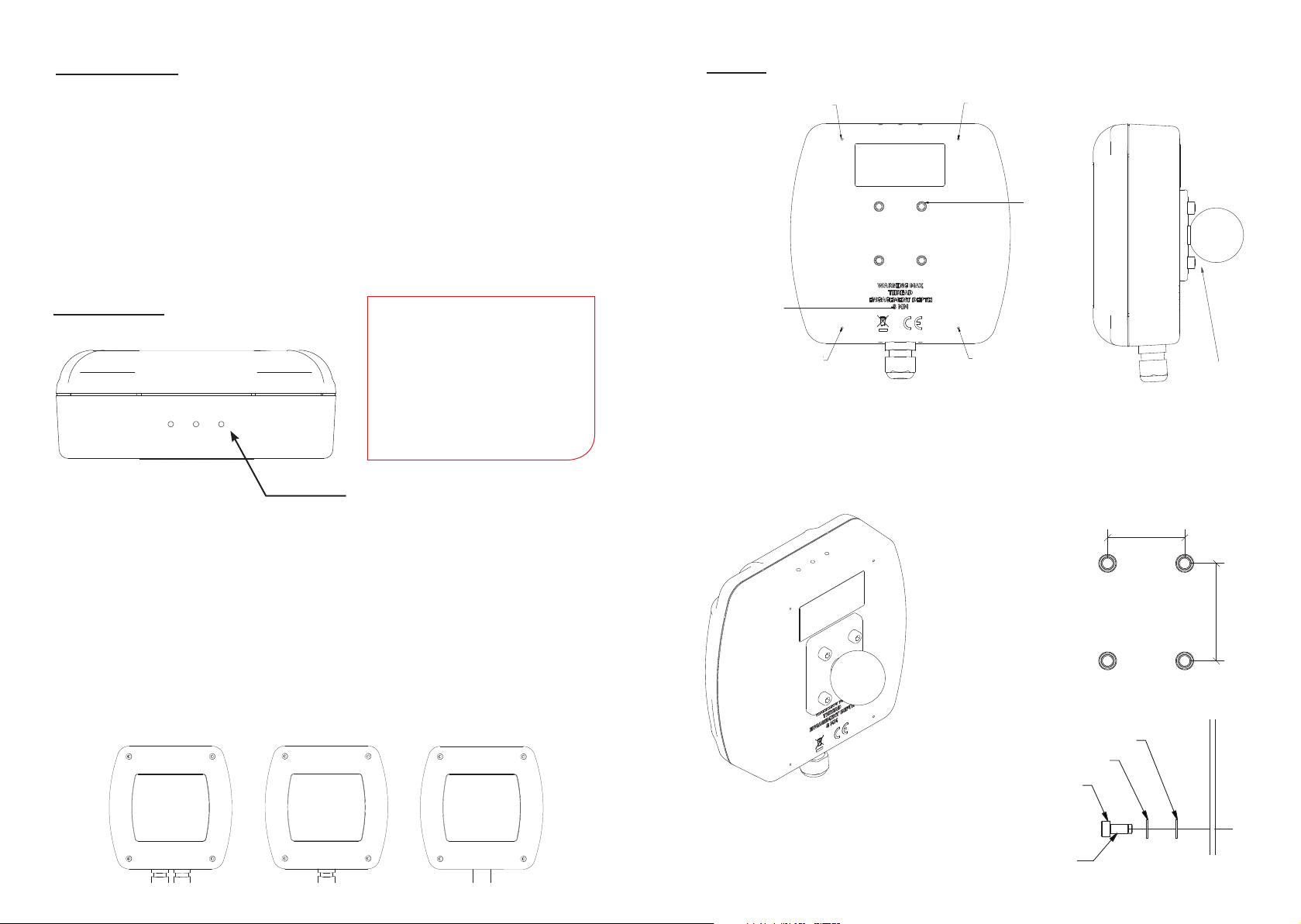
See back cover for 1:1 Drill Point template.
There are two models of the Plus Reader. The Tag Reader model can be used to
provide restricted or controlled access through doors, turnstiles and gates. The Tag
Tester model enables users to quickly and easily check the status of their tags.
Simple LED indication panels on both models highlight whether the reader has
power, the tag can be read, and the tag battery level status.
Both readers are compatible with the Eureka tag range including :
ZoneSafe VibraTag, ZoneSafe High Capacity Tag and ZoneSafe’s standard tag range.
Cable Entry
NOTE:
Please make a note of the serial
number located on the back of
the device for ease of set up. You
will need this number in order
to set up and connect to the
network.
Drill marks
• Supply 24VDC +/- 5% 10W or use the Power over Ethernet (PoE module
needed*). Use a suitible Cat5e data cable to connect comms.
• Run power and data into your device using waterproof cable glands, (Max
16mm Diameter) or internally threaded conduit (Max 20mm diameter).
• Holes can be made by drilling through one of the marked locations on the box.
• For an IP67 application use rated glands or enter through the underside
with suitably sealed conduit. Entry through the back is possible but if ingress
protection is needed then the entry hole must be suitably sealed.
DRILL POINT
DRILL POINT DRILL POINT
THREAD
THREAD DEPTH
DEPTH
DRILL POINT
DRILL POINT
DRILL POINT
DRILL POINTDRILL POINT
AMPS
AMPS
• Alternatively drill holes through the back where shown above.
• To use RAM Mount xtures, attach a 1.5” RAM Mount base plate.
• Back x with the four AMPS holes to suit your application.
30.00
See back
cover for
1:1 AMPS
template.
30.00
Ram Mount
Ball Fixing
0
0
.
8
3
38.00
*sold seperately
M5 PLAIN
M5 PLAIN
M5 INT TOOTH SHAKEPROOF
M5 INT TOOTH SHAKEPROOF
M5 X 0.8mm PITCH
M5 X 0.8mm PITCH
THREAD LOCK
THREAD LOCK
Page 3
Wiring and Range Adjustment
HARDWARE
ADDRESS
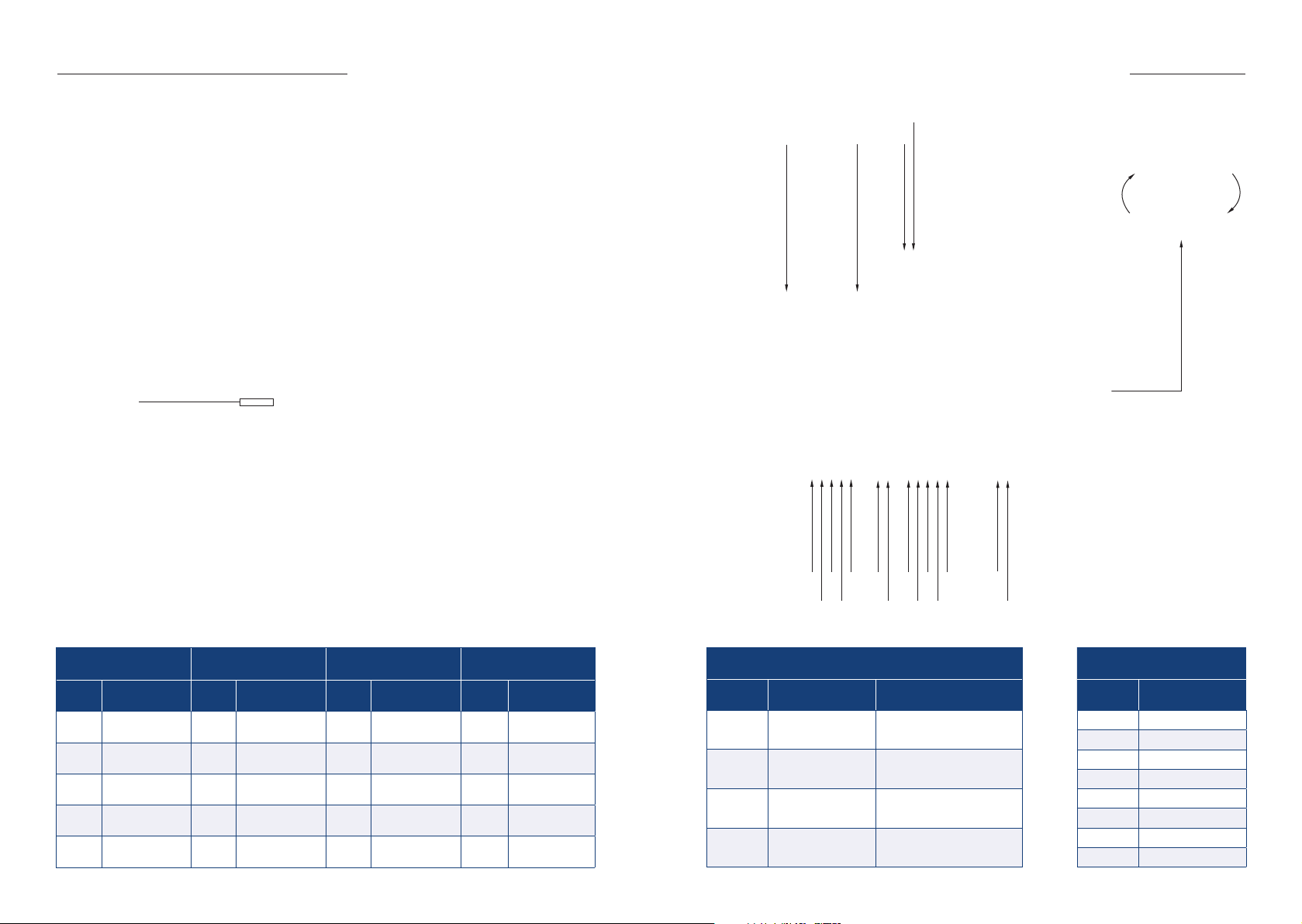
RV1 - Range
Turn clockwise to increase the
2
8
1
1
detection range or anti-clockwise
to reduce the range
CONN1 : ANT
(2 Way for Antenna)
Pin No. Description Pin No. Description Pin No. Description Pin No. Description
1 Antenna - 1 0V 1 0V 1 OV IN
2 Antenna + 2 Input + 2 N/O 2 + 24V IN
CONN2 : INPUT
(2 Way for Volt Free Contacts)
CONN3 & 5 : RELAY 1 & 2
(5 Way)
3 N/C
4 Common
+ 24V OUT
5
(100mA max)
CONN4 : POWER
(2 Way for Power)
5
121
5
3
1
2
4
PCB LED INIDICATORS
ID Description Function
LD1 Ethernet Link
LD2 Ethernet Speed
LD3 Ethernet Activity
LD4 Ethernet Duplex
3
2
4
LED is ON when Ethernet port has
a valid link
LED is ON when Ethernet is in
100Mbps mode
LED blinks when there is activity
on the Ethernet port
LED is ON when Ethernet is in half
duplex mode
1
2
J4 ETHERNET (8 Way)
Pin No. Description
1 BLUE/WHITE
2 BLUE
3 ORANGE/WHITE
4 ORANGE
5 GREEN/WHITE
6 GREEN
7 BROWN/WHITE
8 BROWN
Page 4
Network Connection & Setup
VIEW A-A
1 2 3 4
5
DRILL POINT
DRILL POINT
DRILL POINT
DRILL POINT
AMPS
THREAD DEPTH
VIEW A-A
SCALE 1 : 1
SECTION B-B
SCALE 1.25 : 1
A
B
B
REV: DATE: CHANGE:
STATUS:
CUSTOMER:
SCALE @
DRAWN BY:
REV:
DRAWING NO:
TITLE:
SHEET
A0
AS INDICATED IN ISO 2768-1
TOLERANCE CLASS
LINEAR = f
ANGULA
R = f
BROKEN EDGES = f
1 / 1
UNLESS OTHERWISE STATED
DRILL POINT
DRILL POINT
DRILL POINT
DRILL POINT
AMPS
THREAD DEPTH
Operation
1. Go to http://www.lantronix.com
2. Browse to - Products & Services > Software > Utilities > Device Installer.
3. Download and install the latest version of the Device Installer software on a PC
on the same network as the Plus Reader.
4. Run the Installer, it will automatically start searching for devices on the
network. If device doesn’t show up press the search button.
5. Double click an ‘xPico Wi-Fi’ name to view its properties and values.
6. To access the device enter its IP address (shown in device installer) into a
browser.
7. DHCP Device name = Serial number of device. To rename enter IP address into
browser, change host name > save > apply settings.
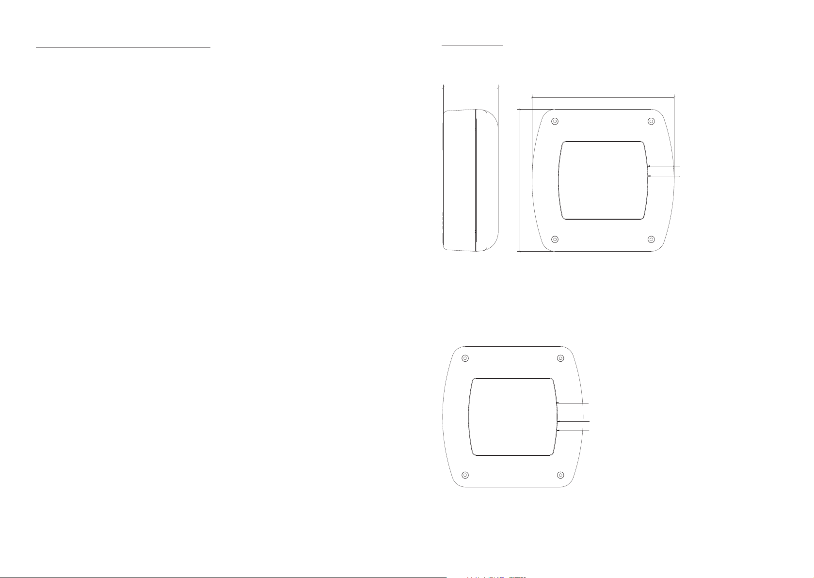
Tag Reader - This type of Plus Reader is typically used for door access systems.
60.00
155.00
POWER INDICATOR
0
0
.
5
5
1
• Power Indicator LED (Flashing LED = Power On
POWER INDICATOR
READ INDICATOR
READ INDICATOR
• Read Indicator LED (3 seconds on = Tag Read)
Tag Tester - This type of Plus Reader also tells the user the battery level of their tag.
POWER INDICATOR
POWER INDICATOR
GOOD BATTERY
GOOD BATTERY
BAD BATTERY
LOW BATTERY
• Power Indicator LED (Flashing LED = Power On
• Good Battery LED (3 seconds on = Tag battery Good)
• Low Battery LED (3 seconds on = Tag battery Low)
Page 5

RFID Systems
Wall Fixing
Template 1:1
30.00
30.00
Wall Fixing
Template 1:1
Avonwood Developments Ltd
Knoll Technology Centre,
Stapehill Road,
Wimborne,
Dorset, United Kingdom,
BH21 7ND
AMPS (Ram Mount)
Fixing Template 1:1
+44 (0) 1202 868000
0
0
.
8
3
38.00
B146773
www.avonwood.co.uk
 Loading...