

Eurapo SV, SV/AF, SH, SH/AF, CV Technical Manual
...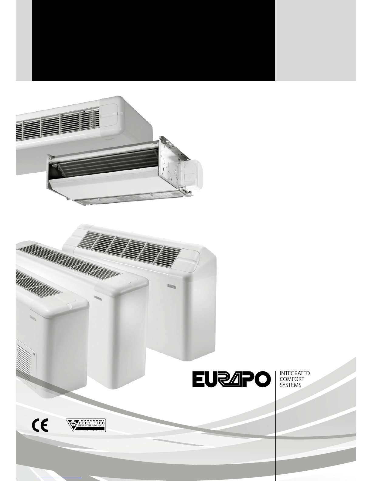
Fancoil units
Sigma - Prisma - Concealed - Low Body
TECHNICAL MANUAL
EN

2

3
INDEX
1. GENERAL INFORMATION
1.1 Applications ...............................................................................4
1.2 Operation ...................................................................................4
1.3 Performances ...........................................................................4
1.4 Operating limits .........................................................................4
1.5 Product range ............................................................................5
1.6 Selection software ..................................................................5
Exploded view SV and SH/AF ............................................6
Exploded view PV and CH ..................................................7
2. MODELS WITH CABINET
2.1 SIGMA Serie: SV-SV/AF Models ........................................8
2.2 SIGMA Serie: SH-SH/AF Models ......................................8
2.3 PRISMA Serie: PV-PV/AF Models ....................................10
2.4 PRISMA Serie: PH-PH/AF Models ..................................10
2.5 LOW BODY Serie: SVR Model .........................................12
2.6 SUGGESTED INSTALLATION ..........................................13
3. MODELS WITHOUT CABINET
3.1 CONCEALED Serie: CV-CV/AF Models ........................14
3.2 CONCEALED Serie: CH-CH/AF Models ......................14
3.3 LOW BODY Serie: CVR Model ........................................16
3.4 SUGGESTED INSTALLATION ..........................................17
4. COMPONENTS
4.1 Inner frame .............................................................................18
4.2 Coils ............................................................................................18
4.3 Fan deck ..................................................................................18
4.4 Electrical components and controls ............................19
4.5 Air filter .....................................................................................19
4.6 Housing ....................................................................................19
5. ELECTRICAL ACCESSORIES
5.1 Electric box CBL10 ...............................................................20
5.2 Electric box CBL20 ..............................................................20
5.3 Electric box CBL30 ..............................................................20
5.4 Electric heater KREL ............................................................20
5.5 Fan speed selectors CSL – CSR ....................................21
5.6 Room temperature thermostat TAD10 ......................21
5.7 Thermostats CML – CMR ................................................21
5.8 Electronic regulators CEL – CER ....................................22
5.9 OMNIBUS digital control ....................................................23
5.9.1 Power Omnibus card for BMS – OPV10 .................23
5.9.2 Display Console – OC236 ............................................23
5.9.3 Analogue Plus Console – OC736 .............................24
5.9.4 Infrared receiver (OC516) and
remote control (OIR30) ..................................................24
5.10 OMNIBUS Supervision .....................................................24
5.10.1 Manager Console – OC436 .......................................24
5.10.2 OTouch – OCB30 ...........................................................24
5.10.3 Onet - OCB50 Webserver ..........................................25
5.11 TM
– Minimum water temperature thermostat ............25
5.12 WS – Water sensor ...........................................................25
5.13 AS – Air sensor ...................................................................26
5.14 CS – Check Sensor ...........................................................26
5.15 AFT – Thermostat .............................................................26
5.15.1 AFT – Anti-frost function ..............................................26
5.15.2 AFT – In combination with electric heater . ........26
5.16 PC – Condensate pump ................................................26
6. REGULATING VALVES
6.1 H3A2 – H2A2 ON/OFF valves ........................................27
6.2 J3AM – J2AM Modulating valves ...................................27
6.3 DT – Shut-off valves ............................................................28
6.4 Four-pipe Compact kit ........................................................29
6.5 FY – Filter .................................................................................29
7. OTHER ACCESSORIES
7.1 CP – Set of feet ......................................................................30
7.2 ZL – Long socle with feet ..................................................30
7.3 PPV – Vertical back panel ..................................................30
7.4 PPH – Horizontal back panel ...........................................30
7.5 PAE/V – Vertical external air intake with manual
damper .....................................................................................30
7.6 PAE/VM – Vertical external air intake with motorized
damper .....................................................................................30
7.7 PAE/H – Horizontal external air intake with manual
damper .....................................................................................31
7.8 PAE/HM – Horizontal external air intake with
motorized damper ...............................................................31
7.9 PAE/HAF – Horizontal external air intake
(for units with frontal air intake) .....................................31
7.10 PM – Air delivery plenum ................................................32
7.11 PM90 – 90° air delivery plenum ..................................32
7.12 PA – Air suction plenum ..................................................32
7.13 PAS – Air suction plenum with spigots ......................33
7.14 PA90 – 90° air suction plenum ....................................33
7.15 RCA – Duct connection....................................................33
7.16 RCCMF – Telescopic air outlet connection ..............34
7.17 RCCAF – 90° Telescopic air intake connection ......34
7.18 GM – Air outlet grill for RCCMF .....................................34
7.19 GA – Air intake grill for RCCAF .......................................34
8. TECHNICAL DATA
8.1 Air volumes ..............................................................................34
8.1.1 Sigma, Prisma, Concealed Serie ..................................34
8.1.2 Low body Serie ...................................................................36
8.2 Cooling capacities .................................................................37
8.2.1 Sigma, Prisma, Concealed Serie .................................37
8.2.2 Low body Serie ..................................................................39
8.3 Heating capacities ................................................................40
8.3.1 Sigma, Prisma, Concealed Serie .................................40
8.3.2 Low body Serie ..................................................................42
8.4 Electrical data ..........................................................................43
9. NOISE LEVELS
9.1 Sound power ...........................................................................44
9.2 Sound pressure in a closed environment ..................44
10. ELECTRICAL CONNECTIONS
......................................................46
EN
1
2
3
4
5
6
7
8
9
10

1
2
3
4
5
6
7
8
9
1. GENERAL INFORMATION
1.1 APPLICATIONS
Fan coils are used to directly treat the air in the room where they are installed.
They can be used both for heating and cooling applications; in the latter case, the air is also dehumidified.
1.2 OPERATION
The effectiveness of a fan coil is due to the large surface area of the finned heat exchanger (coil) where the air drawn from
the room by the fan passes through.
Heating operation: the hot water circulating in the finned coil supplies heat to the air passing through the heat exchanger.
Cooling operation: the chilled water circulating in the finned coil removes heat from the air passing through the heat exchanger.
The air is also dehumidified and the condensed water vapour must be discharged from the unit: suitable drains must therefore
be provided to drain the condensed water that collects in the condensate tray.
1.3 PERFORMANCES
The performance of a fan coil can vary greatly with changes in the temperature and in the amount of water circulating
through the coil, as well as with changes in the temperature and in the amount of air circulating through the coil.
When using the direct expansion coil, thermal performances in cooling and heating depend on the performance of the
condensing unit connected to the fan coil.
The air volume is determined by selecting the proper fan speed (MIN-MED-MAX) through electronic or digital regulators
(also for BMS systems), while the water flow rate is determined by the specifications of the system and of the pump.
Thermal performances of the unit can be optimised by controlling the inlet flow rate of the water with proper regulating
valves (ON/OFF or modulating type), which can be supplied as accessories.
For each model, thermal performances in heating and cooling depend on the number of rows of the coil installed, which
gives the opportunity to make the air treatment suit every condition required.
In cooling function, under the same operating conditions, the more rows the heat exchanger has, the more it will dehumidify.
1.4 OPERATING LIMITS
Each fancoil can work properly only if the operating limits listed below are respected:
• Maximum operating pressure (water side): 1600 kPa
• Maximum pressure of the refrigerant fluid for fancoils with direct expansion: 2400 kPa
• Minimum inlet water temperature in cooling: 5 °C
• Maximum inlet water temperature in cooling: 20 °C
• Minimum inlet water temperature in heating: 35 °C
• Maximum inlet water temperature in heating: 85 °C
4
10
1
2
3
4
5
6
7
8
9
5
EN
10
1.5 PRODUCT RANGE
This manual covers the following models of EURAPO fancoil units:
MODEL INSTALLATION SIZE
SIGMA SERIE
SV with cabinet vertical on the wall/floor (with feet) 110 ÷3 2 8
SV/AF with cabinet and frontal air intake vertical on the floor (without feet) 110 ÷3 2 8
SH with cabinet horizontal on the ceiling 110 ÷3 2 8
SH/AF with cabinet and bottom air intake horizontal on the ceiling 110 ÷3 2 8
PRISMA SERIE
PV with cabinet vertical on the wall/floor (with feet) 110 ÷218
PV/AF with cabinet and frontal air intake vertical on the floor (without feet) 110 ÷218
PH with cabinet horizontal on the ceiling 110 ÷218
PH/AF with cabinet and bottom air intake horizontal on the ceiling 110 ÷218
LOW BODY SERIE
SVR with cabinet vertical on the floor (without feet) 110 ÷21 8
CVR without cabinet vertical and concealed 110 ÷21 8
CONCEALED SERIE
CV without cabinet vertical and concealed 110 ÷3 2 8
CV/AF without cabinet and frontal air intake vertical and concealed 110 ÷3 2 8
CH without cabinet horizontal and concealed 110 ÷3 2 8
CH/AF without cabinet and frontal air intake horizontal and concealed 110 ÷3 2 8
Installation and Operation instructions concerning the software for selection are provided
with the software itself.
1.6 SELECTION SOFTWARE
To facilitate choosing the correct size of a fan coil for any operating condition (including those differing from the standard
ones), EURAPO offers a dedicated computer program which can be downloaded from the ftp address http://ftp.eurapo.it/
and can be updated with automatic upload through internet.

6
1
2
3
4
5
6
7
8
9
10
LEGEND
1. Internal structure
2. Fan deck
3. Electric motor
4. Scroll and impeller
5. Autotransformer
6. Capacitor
7. Electric panel
8. Standard coil (2, 3 or 4 rows)
9. Additional coil
10. Condensate tray
11. Auxiliary drain pan (vertical)
12. Water discharge plastic pipe
13. Grilles
14. Housing
15. Filter
16. Set of feet
17. Fixing slots
SV MODEL
LEGEND
1. Internal structure
2. Fan deck
3. Electric motor
4. Scroll and impeller
5. Autotransformer
6. Capacitor
7. Electric panel
8. Standard coil (2, 3 or 4 rows)
9. Additional coil
10. Condensate tray
11. Auxiliary drain pan (horizontal)
12. Water discharge plastic pipe
13. Grilles
14. Housing
15. Filter
16. Air intake panel
17. Fixing screws
18. Back inner panel
19. Fixing slots
SH/AF MODEL
13
14
11
9
8
16
12
10
15
15
16
17
14
12
13
10
18
8
8
2
6
5
3
4
7
19
1
11
3
5
4
6
2
1
17
7

7
EN
1
2
3
4
5
6
7
8
9
10
LEGEND
1. Internal structure
2. Fan deck
3. Electric motor
4. Scroll and impeller
5. Autotransformer
6. Capacitor
7. Electric panel
8. Standard coil (2 or 3 rows)
9. Additional coil
10. Condensate tray
11. Auxiliary drain pan (vertical)
12. Water discharge plastic pipe
13. Grilles
14. Housing
15. Filter
16. Set of feet
17. Fixing slots
PV MODEL
LEGEND
1. Internal structure
2. Fan deck
3. Electric motor
4. Scroll and impeller
5. Autotransformer
6. Capacitor
7. Electric panel
8. Standard coil (2, 3 or 4 rows)
9. Additional coil
10. Condensate tray
11. Auxiliary drain pan (horizontal)
12. Water discharge plastic pipe
13. Filter
14. Fixing slots
CH MODEL
13
14
1
11
16
8
9
12
10
1
11
8
9
1210
13
5
4
7
14
2
6
3
15
5
6
2
17
3
4
7
2. MODELS WITH CABINET
2.1 SIGMA SERIE:
SV – SV/AF MODELS
Vertical units with upper air outlet and bottom (SV) or frontal
(SV/AF) air intake, to be installed on the wall (SV) or on the
floor (both models, but with a set of feet in white RAL 9003
for SV model).
• grilles can be adjusted in all four directions and are made
of heat-resistant ABS
• models equipped with auxiliary drain pan
• 2 pipe systems: 2, 3 or 4 row coils; on 2 or 3 row coil units
an electric heater can also be mounted
• 4 pipe systems: additional 1 row coil can be added to units
with a 2 or 3 row coil
• direct expansion system: 3 row direct expansion coil
• standard colour: white casing (RAL 9003) with white grilles
and access doors (RAL 9016)
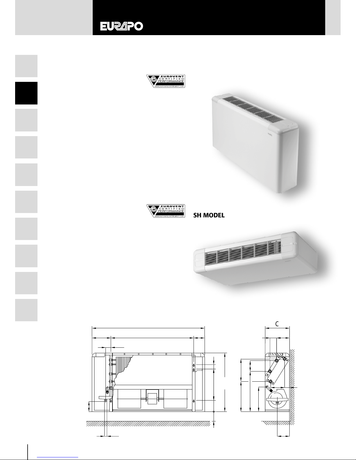
2.2 SIGMA SERIE:
SH – SH/AF MODELS
Horizontal units for ceiling installation with frontal air discharge
and rear (SH) or bottom (SH/AF) air intake.
• grilles can be adjusted in all four directions and are made
of heat-resistant ABS
• models equipped with auxiliary drain pan
• 2 pipe systems: 2, 3 or 4 row coils; in 2 or 3 row coil units
an electric heater can also be mounted
• 4 pipe systems: additional 1 row coil can be added to units
with a 2 or 3 row coil
• direct expansion system: 3 row direct expansion coil
• standard colour: white casing (RAL 9003) with white grilles
and access doors (RAL 9016)
8
1
2
3
4
5
6
7
8
9
10
U
D
C
A
W
N
H
I
B
G
F
J
E
X
Q
R
ø
V
Z
SP0T
SH MODEL
SV MODEL
SV MODEL
9
EN
1
2
3
4
5
6
7
8
9
10
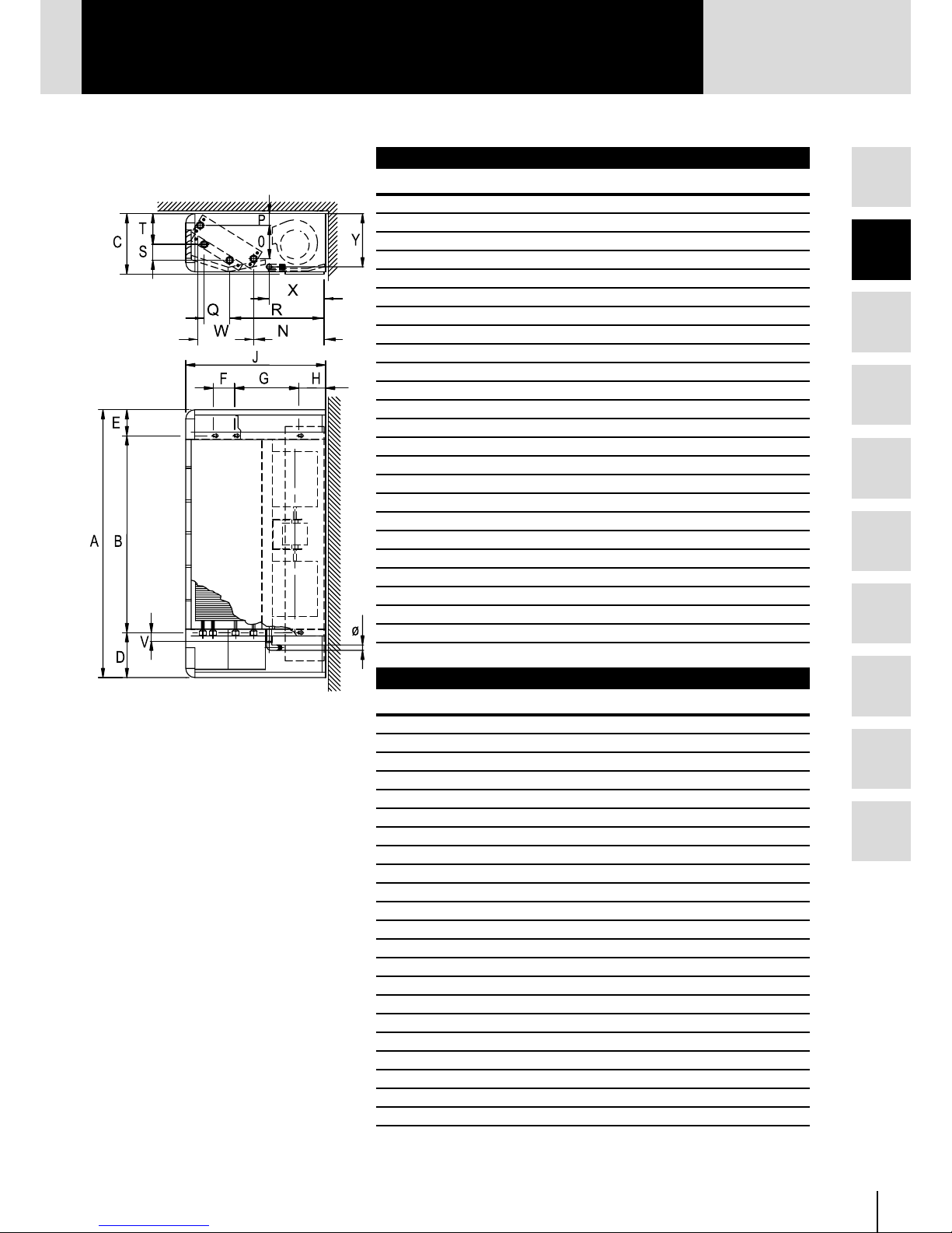
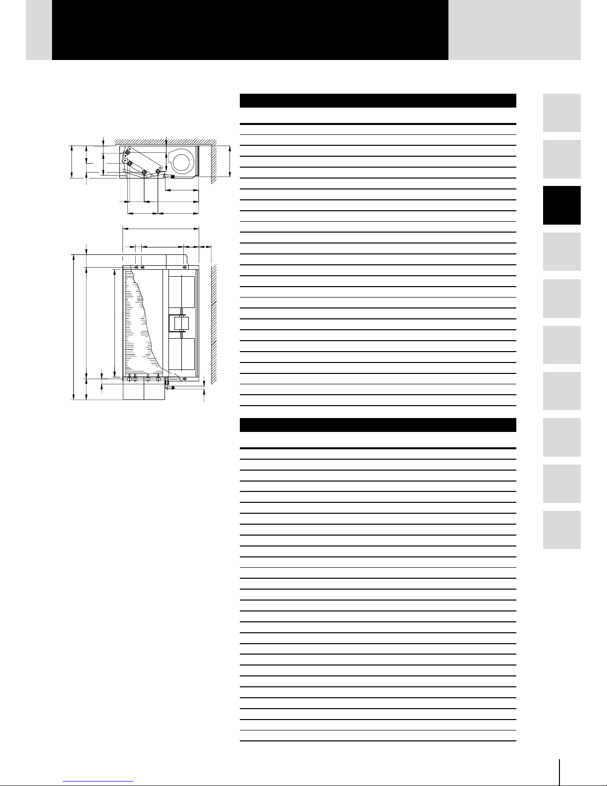
SV - SH Dimensions and weights
Size 110
112 114 216 218 220 222 224 226 328
A 648 773 898 1023 114 8 1273 1273 1523 1523 177 3
B 374 499 624 749 874 999 999 1249 1249 1499
C 224 224 224 224 224 254 254 254 254 254
D 174 174 174 174 174 174 174 174 174 174
E 100 10 0 10 0 100 100 100 100 100 100 100
F 40 40 40 40 40 40 40 40 40 40
G 280 280 280 280 280 356 356 356 356 356
H 101 101 101 101 101 101 101 101 101 101
I 85 85 85 85 85 85 85 85 85 85
J 538 538 538 538 538 614 614 614 614 614
N 266 266 266 266 266 299 299 299 299 299
O 113 113 113 113 113 138 138 138 138 138
P 48 48 48 48 48 53 53 53 53 53
Q 87 87 87 87 87 87 87 87 87 87
R 335 335 335 335 335 409 409 409 409 409
S 50 50 50 50 50 50 50 50 50 50
T 117 117 117 117 117 135 135 135 135 135
U 90 90 90 90 90 116 116 116 116 116
V 47 47 47 47 47 47 47 47 47 47
W 195 195 195 195 195 238 238 238 238 238
X 219 219 219 219 219 252 252 252 252 252
Z 109 109 10 9 109 109 122 12 2 122 122 122
Ø 20 20 20 20 20 20 20 20 20 20
kg 18 20 23 28 31 41 44 52 52 58
SV/AF - SH/AF Dimensions and weights
Size 110
112 114 216 218 220 222 224 226 328
A 648 773 898 1023 114 8 127 3 1273 152 3 1523 1773
B 374 499 624 749 874 999 999 1249 1249 1499
C 233 233 233 233 233 263 263 263 263 263
D 174 174 174 174 174 174 174 174 174 174
E 100 10 0 10 0 100 100 100 100 100 100 100
F 40 40 40 40 40 40 40 40 40 40
G 280 280 280 280 280 356 356 356 356 356
H 101 101 101 101 101 101 101 101 101 101
J 538 538 538 538 538 614 614 614 614 614
N 266 266 266 266 266 299 299 299 299 299
O 113 113 113 113 113 138 138 138 138 138
P 48 48 48 48 48 53 53 53 53 53
Q 87 87 87 87 87 87 87 87 87 87
R 335 335 335 335 335 409 409 409 409 409
S 50 50 50 50 50 50 50 50 50 50
T 117 117 117 117 117 135 135 135 135 135
V 28 28 28 28 28 28 28 28 28 28
W 195 195 195 195 195 238 238 238 238 238
X 219 219 219 219 219 252 252 252 252 252
Y 205 205 205 205 205 235 235 235 235 235
Ø 20 20 20 20 20 20 20 20 20 20
kg 19 21 24 30 32 43 46 54 54 61
SH/AF MODEL
10
1
2
3
4
5
6
7
8
9
10
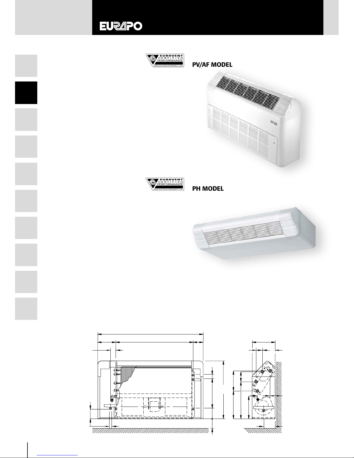
2.3 PRISMA SERIE:
PV – PV/AF MODELS
Vertical units with upper air outlet and bottom (PV) or frontal
(PV/AF) air intake, to be installed on the wall (PV) or on the
floor (both models, but with a set of feet in white RAL 9003
for PV model).
• grilles can be adjusted in all four directions and are made
of heat-resistant ABS
• models equipped with auxiliary drain pan
• 2 pipe systems: 2 or 3 row coils; on 2 row coil units an
electric heater can also be mounted
• 4 pipe systems: additional 1 row coil can be added to
units with a 2 or 3 row coil
• direct expansion system: 3 row direct expansion coil
• standard colour: white casing (RAL 9003), with white
grilles and access doors (RAL 9016)
2.4 PRISMA SERIE:
PH – PH/AF
MODELS
Horizontal units for ceiling installation with frontal air discharge
and rear (PH) or bottom (PH/AF) air intake.
Designed for heating only.
• grilles can be adjusted in all four directions and are made
of heat-resistant ABS
• 2 pipe systems: 2 or 3 row coils; in 2 row coil units an
electric heater can also be mounted
• standard colour: white casing (RAL 9003) with white
grilles and access doors (RAL 9016)
U
D
H
I
F
G
B
A
E
X
R
Q
N
W
J
C
V
ø
S
Z
P0
T
PV MODEL
PV/AF MODEL
PH MODEL

11
EN
1
2
3
4
5
6
7
8
9
10
A
D
B
E
F
G
H
J
C
NW
0
P
PV - PH Dimensions and weights
Size 110
112 114 216 218
A 648 773 898 1023 1148
B 374 499 624 749 874
C 226 226 226 226 226
D 174 174 174 174 174
E 100 100 100 100 100
F 40 40 40 40 40
G 280 280 280 280 280
H 101 101 101 101 101
I 85 85 85 85 85
J 560 560 560 560 560
N 266 266 266 266 266
O 113 113 113 113 113
P 48 48 48 48 48
Q 87 87 87 87 87
R 355 355 355 355 355
S 50 50 50 50 50
T 117 117 117 117 117
U 90 90 90 90 90
V 47 47 47 47 47
W 195 195 195 195 195
X 219 219 219 219 219
Z 109 109 109 109 109
Ø 20 20 20 20 20
kg 17 20 23 27 31
PV /AF - PH/AF Dimensions and weights
Size 110
112 114 216 218
A 648 773 898 1023 114 8
B 374 499 624 749 874
C 235 235 235 235 235
D 174 174 174 174 174
E 100 100 100 100 100
F 40 40 40 40 40
G 280 280 280 280 280
H 101 101 101 101 101
J 560 560 560 560 560
N 266 266 266 266 266
O 113 113 113 113 113
P 48 48 48 48 48
W 195 195 195 195 195
Ø 20 20 20 20 20
kg 28 21 24 28 32
PH/AF MODEL
12
1
2
3
4
5
6
7
8
9
10
SVR MODEL
SVR Dimensions and weights
Size 110
112 114 216 218
A 648 773 898 1023 1148
B 374 499 624 749 874
C 254 254 254 254 254
D 174 174 174 174 174
E 100 100 100 100 100
G 170 170 170 170 170
H 101 101 101 101 101
J 430 430 430 430 430
N 245 245 245 245 245
O 15 4 154 154 154 154
P 31 31 31 31 31
Q 47 47 47 47 47
R 304 304 304 304 304
S 88 88 88 88 88
T 87 87 87 87 87
U 65 65 65 65 65
V 47 47 47 47 47
W 84 84 84 84 84
X 214 214 214 214 214
Z 109 109 109 109 109
Ø 20 20 20 20 20
kg 15 17 22 23 26
T
P0
Y
Z
U
V
ø
B
S
H
J
G
X
Q
R
N
W
C
D E
A
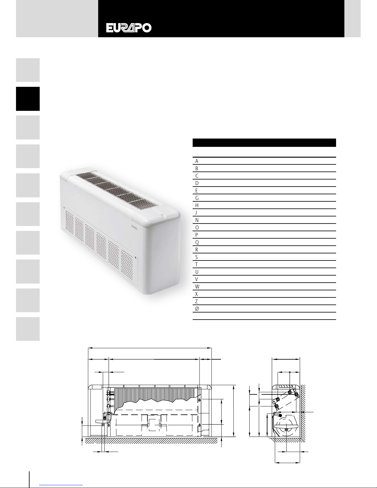
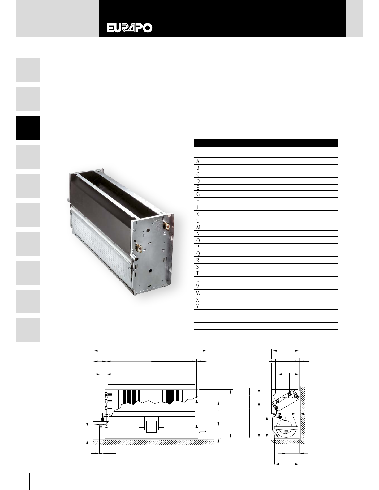
2.5 LOW BODY SERIE:
SVR MODEL
Vertical unit in a reduced height (430 mm) with upper air outlet and frontal air intake, to be installed on the floor.
• grilles can be adjusted in all four directions and are made of heat-resistant ABS
• model equipped with auxiliary drain pan
• 2 pipe systems: 2 or 3 row coils; on 2 row coil units an electric heater can also be mounted
• 4 pipe systems: additional 1 row coil can be added to units with a 2 or 3 row coil
• standard colour: white casing (RAL 9003) with white grilles and access doors (RAL 9016)
SV
FA/HSHP
PAE/HAF
SV/AF
13
IT
1
2
3
4
5
6
7
8
9
10
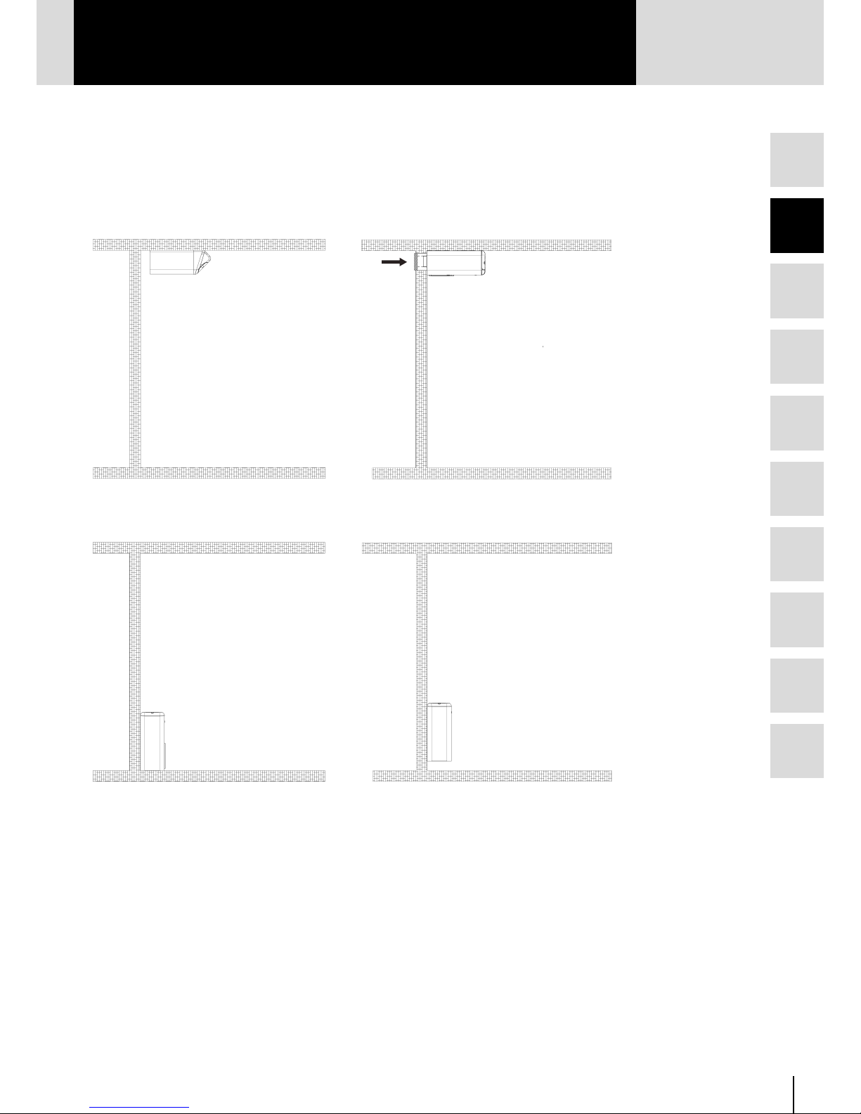
2.6 SUGGESTED INSTALLATION
PH SH/AF
PAE/HAF
SV/AF SV
14
1
2
3
4
5
6
7
8
9
10
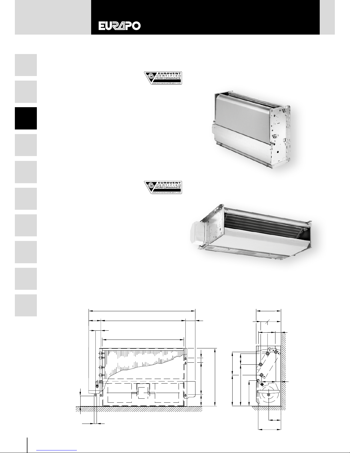
3. MODELS WITHOUT CABINET
3.1 CONCEALED SERIE:
CV – CV/AF MODELS
Vertical units for concealed installation with upper air outlet and
bottom (CV) or frontal (CV/AF) air intake.
• models equipped with auxiliary drain pan
• 2 pipe systems: 2, 3 or 4 row coils; in all units an electric
heater can also be mounted
• 4 pipe systems: additional 1 row coil can be added
to units with a 2 or 3 row coil; in 4 row coil units, the
additional 1 row coil is fitted on the air outlet connection
• direct expansion system: 3 row direct expansion coil
3.2 CONCEALED SERIE:
CH – CH/AF MODELS
Horizontal units for concealed installation, with frontal air outlet
and rear (CH) or bottom (CH/AF) air intake.
• models equipped with auxiliary drain pan
• 2 pipe systems: 2, 3 or 4 row coils; in all units an electric
heater can also be mounted
• 4 pipe systems: additional 1 row coil can be added
to units with a 2 or 3 row coil; in 4 row coil units, the
additional 1 row coil is fitted on the air outlet connection
• direct expansion system: 3 row direct expansion coil
W
N
ø
U
H
F
J
G
D
V
A
M
B
E
Y
P
R
X
Z
Q
0
L
C
K
TS
CV/AF MODEL
CV MODEL
CH/AF MODEL
15
IT
1
2
3
4
5
6
7
8
9
10
D
M
A
B
E
F
C
K
L
G
HJI
Y
T
S
O
P
V
ø
RQ
W N
X
CH - CH/AF Dimensions and weights
Size
110
112 114 216 218 220 222 224 226 328
A 574 699 824 949 1074 119 9 119 9 1449 1449 1699
B 374 499 624 749 874 999 999 1249 1249 1499
C 215 215 215 215 215 245 245 245 245 245
D 128 128 128 128 128 128 128 128 128 128
E 72 72 72 72 72 72 72 72 72 72
F 40 40 40 40 40 40 40 40 40 40
G 280 280 280 280 280 356 356 356 356 356
H 101 101 101 101 101 101 101 101 101 101
I 85 85 85 85 85 85 85 85 85 85
J 505 505 505 505 505 581 581 581 581 581
K 110 110 110 110 110 125 125 125 125 125
L 55 55 55 55 55 60 60 60 60 60
M 349 474 599 724 849 974 974 1224 1224 1474
N 266 266 266 266 266 299 299 299 299 299
O 113 113 113 113 113 138 138 138 138 138
P 48 48 48 48 48 53 53 53 53 53
Q 87 87 87 87 87 87 87 87 87 87
R 355 355 355 355 355 409 409 409 409 409
S 50 50 50 50 50 50 50 50 50 50
T 117 117 117 117 117 135 135 135 135 135
V 28 28 28 28 28 28 28 28 28 28
W 195 195 195 195 195 238 238 238 238 238
X 219 219 219 219 219 252 252 252 252 252
Y 205 205 205 205 205 235 235 235 235 235
Ø 20 20 20 20 20 20 20 20 20 20
kg 10 13 16 19 22 29 31 38 38 42
CV - CV/AF Dimensions and weights
Size
110
112 114 216 218 220 222 224 226 328
A 555 680 805 930 1055 118 0 118 0 1430 1430 1680
B 374 499 624 749 874 999 999 1249 1249 1499
C 215 215 215 215 215 245 245 245 245 245
D 109 109 109 109 109 10 9 109 109 109 109
E 72 72 72 72 72 72 72 72 72 72
F 40 40 40 40 40 40 40 40 40 40
G 280 280 280 280 280 356 356 356 356 356
H 101 101 101 101 101 101 101 101 101 101
J 505 505 505 505 505 581 581 581 581 581
K 110 110 110 110 110 125 125 125 125 125
L 55 55 55 55 55 60 60 60 60 60
M 349 474 599 724 849 974 974 1224 1224 1474
N 266 266 266 266 266 299 299 299 299 299
O 113 113 113 113 113 138 138 138 138 138
P 48 48 48 48 48 53 53 53 53 53
Q 87 87 87 87 87 87 87 87 87 87
R 355 355 355 355 355 409 409 409 409 409
S 50 50 50 50 50 50 50 50 50 50
T 117 117 117 117 117 135 135 135 135 135
U 90 90 90 90 90 116 116 116 116 116
V 47 47 47 47 47 47 47 47 47 47
W 195 195 195 195 195 238 238 238 238 238
X 219 219 219 219 219 252 252 252 252 252
Y 200 200 200 200 200 230 230 230 230 230
Z 109 109 10 9 109 109 122 12 2 122 122 122
Ø 20 20 20 20 20 20 20 20 20 20
kg 10 13 16 19 22 29 31 38 38 42
CH MODEL
16
1
2
3
4
5
6
7
8
9
10
CVR MODEL
CVR Dimensions and weights
Size 110
112 114 216 218
A 555 680 805 930 1055
B 374 499 624 749 874
C 230 230 230 230 230
D 10 8 108 108 108 108
E 73 73 73 73 73
G 17 0 170 17 0 170 17 0
H 101 101 101 101 101
J 395 395 395 395 395
K 61 61 61 61 61
L 349 474 599 724 849
M 127 12 7 127 127 127
N 245 245 245 245 245
O 154 154 154 154 154
P 31 31 31 31 31
Q 47 47 47 47 47
R 304 304 304 304 304
S 88 88 88 88 88
T 87 87 87 87 87
U 65 65 65 65 65
V 47 47 47 47 47
W 84 84 84 84 84
X 214 214 214 214 214
Y 201 2 01 201 201 201
Z 10 9 109 109 109 109
Ø 20 20 20 20 20
kg 9 11 14 16 19
D
A
B
L
E
H
G
J
C
M
K
Z
Y
ø
U
V
W
N
R
X
Q
0 P
S T
3.3 LOW BODY SERIE: CVR MODEL
Vertical unit in a reduced height (395 mm) for concealed installation, with upper air outlet and frontal air intake.
• model equipped with auxiliary drain pan
• 2 pipe systems: 2 or 3 row coils; on 2 row coil units an electric heater can also be mounted
• 4 pipe systems: additional 1 row coil can be added to units with a 2 or 3 row coil
 Loading...