

EURA DRIVES EM30-0007S2, EM30-0015T3, EM30-0015S2, EM30-0007T3, EM30-0004S2 Safety Instructions, Installation & Operating Manual
...
FREQUENCY INVERTER
EM30
0,4kW – 7,5kW
Safety instructions Installation
& operating manual
www.euradrives.eu
Software Version 1.03
© 2015 EURA Drives GmbH

·0·
1
1
2
3
3
4
5
6
6
8
9
9
10
12
12
13
14
15
16
16
18
19
21
24
26
27
32
32
CONTENTS
I. Product ……………………………………………………………….. …
1.1 Product model naming rule……………………………………
1.2 Optional function naming rule…………………………………
1.3 Nameplate……..………………………………………………
1.4 Technical parameters….………………………………………
1.5 Technical Specifications ………………………………………
1.6 Appearance………………………………………………….…
1.7 Designed Standards for Implementation…………….….……
1.8 Safe Instructions and Precautions……………………….……
1.9 Examination and Maintenance…………………………..……
II. Keypad panel………………………………………………………..
2.1 Panel Illustrations………………………………………………
2.2 Panel Structure………………………………………………. …
2.3 Panel Operating ………………………………………………
2.4 Parameters Setting ……………………………………………
2.5 Function Codes Switchover In/Between Code-Groups…..……
2.6 Operating instructions of 4-line LCD interface switch……….
2.7 Panel Display …………………………………………………
III. Installation & Connection ………………………………………………
3.1 Periphery Wiring……………………………………………….
3.2 Installation………………………………………………….…
3.3 Connection…………………………………………………….
3.4 Function of Control Terminals……………………………………
3.5 Measurement of Main Circuit……………………………………
3.6 Overall Connection………………………………..…….……
3.7 Solutions of Conduction and Radiation Interference…………..
IV. Operation and Simple Running ………………………………………
4.1 Basic conception………………………………………………
EM30

EM30
·1·
33
36
41
41
50
58
68
71
74
77
84
88
92
93
97
99
101
101
101
102
102
103
103
104
106
107
110
111
113
113
115
4.2 Keypad panel and operation method……………………………
4.3 Illustration of basic operation…………………………………
V. Function Parameters ……………………………………………………
5.1 Basic Parameters…………………………………………………
5.2 Operation Control …………………………………………….. …
5.3 Multifunctional Input and Output Terminals………………………
5.4 Analog Input and Output………………………………….………
5.5 Pulse Input and Output control………………………….…………
5.6 Multi-stage Speed Control….………………….…………………
5.7 Auxiliary Functions…..……………………..…….…………
5.8 Malfunction and Protection………………….……………………
5.9 Parameters of the motor….……………………..……………
5.10 Communication parameters………..……………………….……
5.11 PID parameters………………………………………………
5.12 Torque control parameters………………………………….
5.13 Parameters Display…………………………………………
VI. Maintenance....................................................................................
6.1 Daily Inspection....................................................................
6.2 Periodic Maintenance............................................................
6.3 Exchange of Vulnerable Parts...............................................
6.4 Storage..................................................................................
VII. Motor……………………………………………………………..
7.1 Nameplate…………………………………………………..
7.2 Naming Rule…………………………………………………
7.3 Motor Technical Specification……………………………….
7.4 Motor Type…………………………………………………...
7.5 Reference Table of inverter and motor……………………..
7.6 Motor Installation Size………………………………………
7.7 Installation…………………………………………………..
7.8 Trouble Shooting…………………………………………..
7.9 Maintenance & Servicing………………………………….

·2·
116
119
121
123
124
134
Appendix 1 Trouble Shooting…………………………………..…….…
Appendix 2 Reference Wiring of Water System……………..…….……
Appendix 3 Products and Structure…..……………..…………..……
Appendix 4 Selection of Braking Resistance……………..………….….
Appendix 5 Communication Manual……..………….…………. ……
Appendix 6 Zoom Table of Function Code……………………………
.
EM30
EM30
·1·
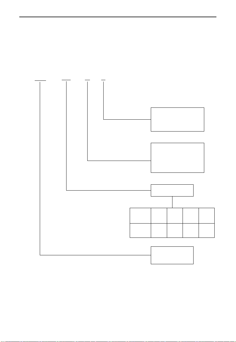
EM30
0007 T3 J1
Structure Code:
J1: 270*190*165
J2: 338*228*193.5
Input Voltage:
T3: 3-phase 380VAC Input
S2: 1-phase 220VAC Input
T2: 3-phase 220VAC Input
Motor Power
Mark
Power
(kW)
0004
0007 0015
„„
0.4 0.75
1.5
„„
Realation
Product Series:
EM30 series
I. Product
This manual offers a brief introduction of the installation connection, parameters setting
and operations for EM30 series inverters, and should therefore be properly kept. Please
contact manufacturer or dealer in case of any malfunction during application.
1.1 Product model naming rule
·2·
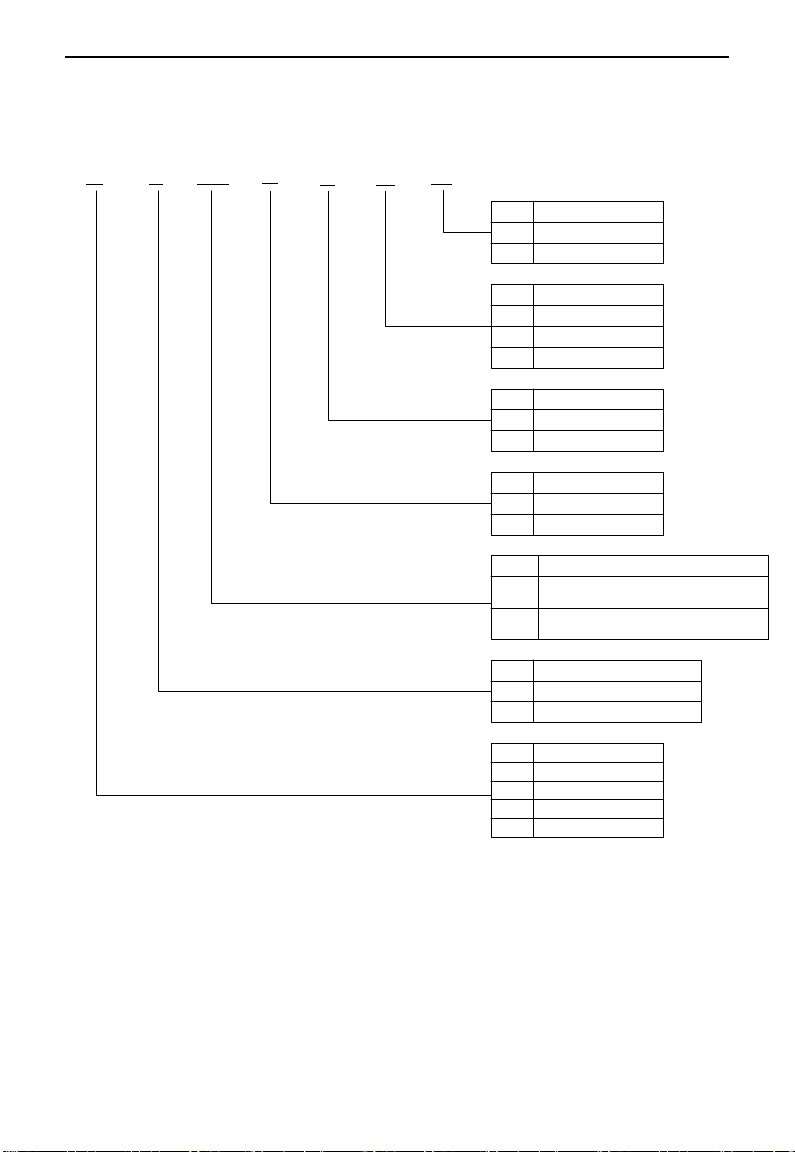
1.2 Optional function naming rule
U5 F2
AC02
B1
R3 M1
IC1
Mark Installation Type
None
IC1
No wall-mounted bracket
Wall-mounted bracket
Mark Motor Type
None
M1
M2
No motor-mounted
Induction Motor
PM synchronous Motor
Mark
Filter Type
None
No filter
R3 C3 level filter
Mark
None
B1
Brake Mode
No braking unit
Built-in braking unit
Mark
Keypad Panel Type
AC02
AC04
AC English keypad panel, 4-line LCD display,
without potentiometer
AC Chinese keypad panel, 4-line LCD display,
without potentiometer
Mark
Field Bus Type
None
F2
MODBUS with terminal interface
None
Mark
None
Certification Type
U
U1
U5
None
UL
CE
UL+CE
EM30
EM30
·3·
Power
supply
Model
Motor
Power
(kW)
Rated
Input
Current
(A)
Rated
Output
Current
(A)
Input
Protection
Current
(A)
Efficiency
(%)
1Ph
230V
EM30-0004S2
0.4 6 2.5
10
≥95
EM30-0007S2
0.75
10
4.5
18.1
≥96
EM30-0015S2
1.5
14 7 25.2
≥96
EM30-0022S2
2.2
20.0
10
32.0
≥96
3Ph
400v
EM30-0007T3
0.75
3.0 2 6.5
≥95
EM30-0015T3
1.5 5 4
11
≥95
EM30-0022T3
2.2
7.5
6.5
15.0
≥96
EM30-0030T3
3.0 8 7
16
≥96
EM30-0040T3
4.0
11.0 9 21.0
≥96
EM30-0055T3
5.5
14.0
12
29.0
≥96
EM30-0075T3
7.5
18.5
17
34.0
≥96
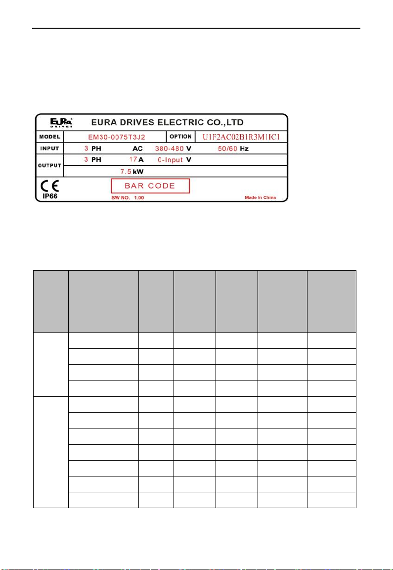
1.3 Nameplate
Taking for instance the EM30 series 7.5kW inverter with 3-phase 400V input, its
nameplate is illustrated as Fig 1-1.
3Ph AC: 3-phase input;
380~480V, 50/60Hz: Input voltage range and rated frequency.
3Ph: 3-phase output; 17A, 7.5kW: Rated output current and power;
Fig 1-1 Nameplate
Note: Integrated inverter model include product model and optional function model. Make
sure to fill with complete integrated inverter model to avoid mistakes when making an
order.
1.4 Technical parameters

·4·
1.5 Technical Specifications
Items
Contents
Input
Rated Voltage Range
T3 380V-480V(+10%/-15%); S2/T2 220V-240V (±15%)
Rated Frequency
50/60Hz
Output
Rated Voltage Range
3-Phase: 0-INPUT(V)
Frequency Range
Vector Control Model: 0~500.00Hz;
VF Model: 0~650.00Hz
Control
Mode
Control Mode
Induction Motor: Sensorless Vector Control (SVC), V/F control;
PMSM: open-loop vector control (SVC)
Carrier Frequency
0.8~16KHz; Fixed carrier-wave and random carrier-wave (F159)
Modulation Mode
Space Vector PWM
Speed-control Scope
Induction Motor-SVC 1:100; PMSM-SVC 1:20;
Steady Speed Precision
±0.5%(SVC)
Torque Response
<20ms(SVC)
Torque Control Precision
±5%(SVC)
Start Torque
0.5 Hz/100% (VVVF); 0.5Hz/150%(SVC)
DC Braking
DC braking frequency: 0.20-50.00 Hz,;
Braking time: 0.00~30.00s; Braking current: 0.0~100%
Operation
Function
Jogging Control
Jogging frequency range: min frequency~ max frequency,
Jogging acceleration/deceleration time: 0.1~3000.0s
Frequency Setting mode
Potentiometer or external analog signal (0~5V, 0~10V,
0~20mA); Keypad (terminals) up/down key; External control
logic and self-circulation setting.
Main Frequency Source
Digital given memory, external analogue AI1, AI2, input
pulse frequency given(100KHZ), digital given without
memory, PID, MODBUS
Auxiliary Frequency Source
Flexible auxiliary frequency trim and the operate mode of main
and auxiliary frequency.
Auto voltage regulation
(AVR)
When source voltage changes, the modulation rate can be
adjusted automatically, so that the output voltage is unchanged.
Analog input
2-channel(AI1/AI2)
Analog output
2-channel (AO1/AO2)
Digit input
5-channel general-form input;
1-channel high-speed pulse input
Max frequency: 100Khz,Internal impedance: 3.3KΩ;
Digit output
1-channel DO1
Relay output
2-channel programmable relay output
Others
Built-in PID adjusting, oscillation inhabitation, common DC
bus, auto carrier modulation, auto fast current-limiting, I/O
terminals self-checking function and OE automatic adjustment.
Keypad
4-line LCD
Support
Parameter copy
Clone module supported.
Protection
Function
Power supply under-voltage, phase loss, DC over-voltage, over-current, inverter overload,
motor overload, output phase loss, overheat, external disturbance, parameter measure failure,
analog line disconnected protection, DC-GND short circuit, water shortage protection,
pressure protection, dormant state.
Table1-1 Technical Specifications for EM 30 Series Inverters
EM30
EM30
·5·
Environmental
Conditions
Environment Temperature
-10℃~+40℃
Environment Humidity
Below 90% (no water-bead coagulation)
Vibration Strength
4G
Height above sea level
1000m or below(Derating use when above 1000m)
Protection
level
IP66
Applicable
Motor
0.4~7.5kW
Efficiency
≥93%
Others
Cooling Mode
Force-air cooling
Braking Unit
Built-in braking unit needs external braking resistor.
Fan
Draught fan is pluggable.
Installation Mode
Support installing with motor
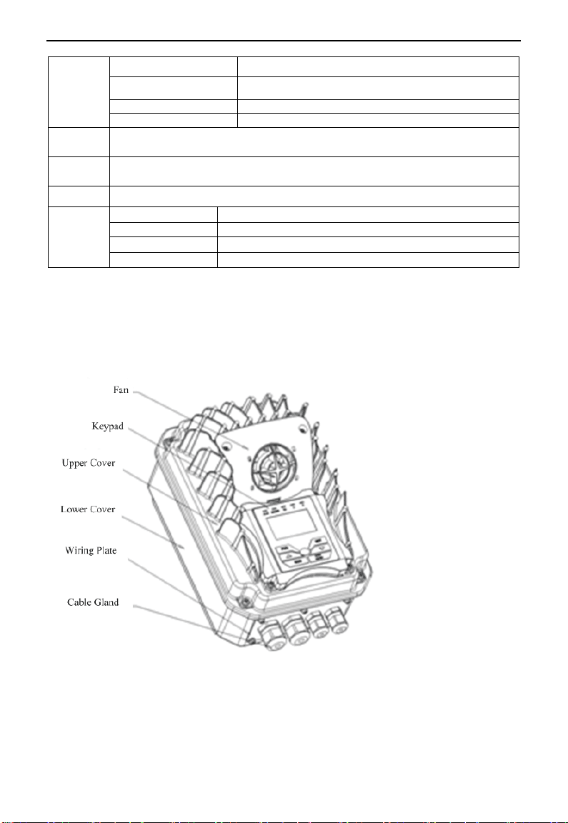
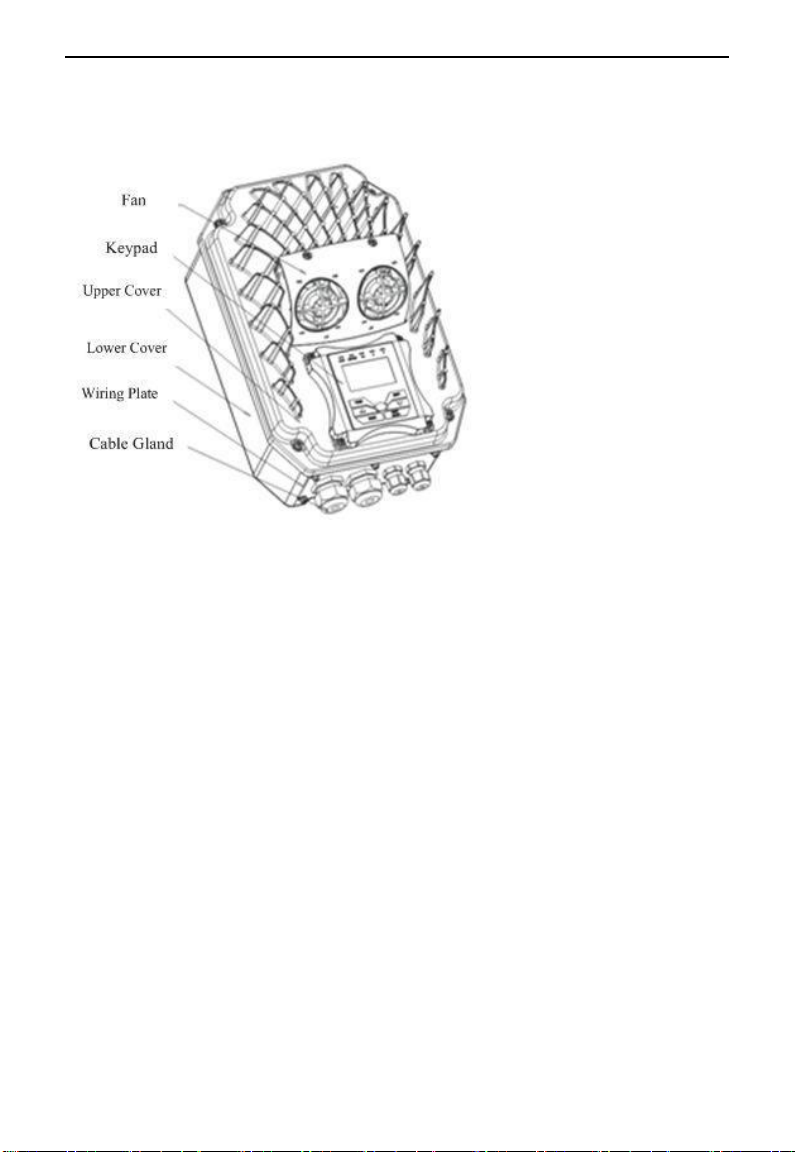
1.6 Appearance
The external structure of EM30 series inverter: die-casting aluminum housing,
anti-fingerprints fabrication processing, unique shape, high strength, good tenacity and
convenience for maintenance. Taking EM30-0022T3J1 for instance, the external
appearance and structure are shown as below in Fig1-2.
Fig 1-2 Appearance and Structure
EM30
·6·
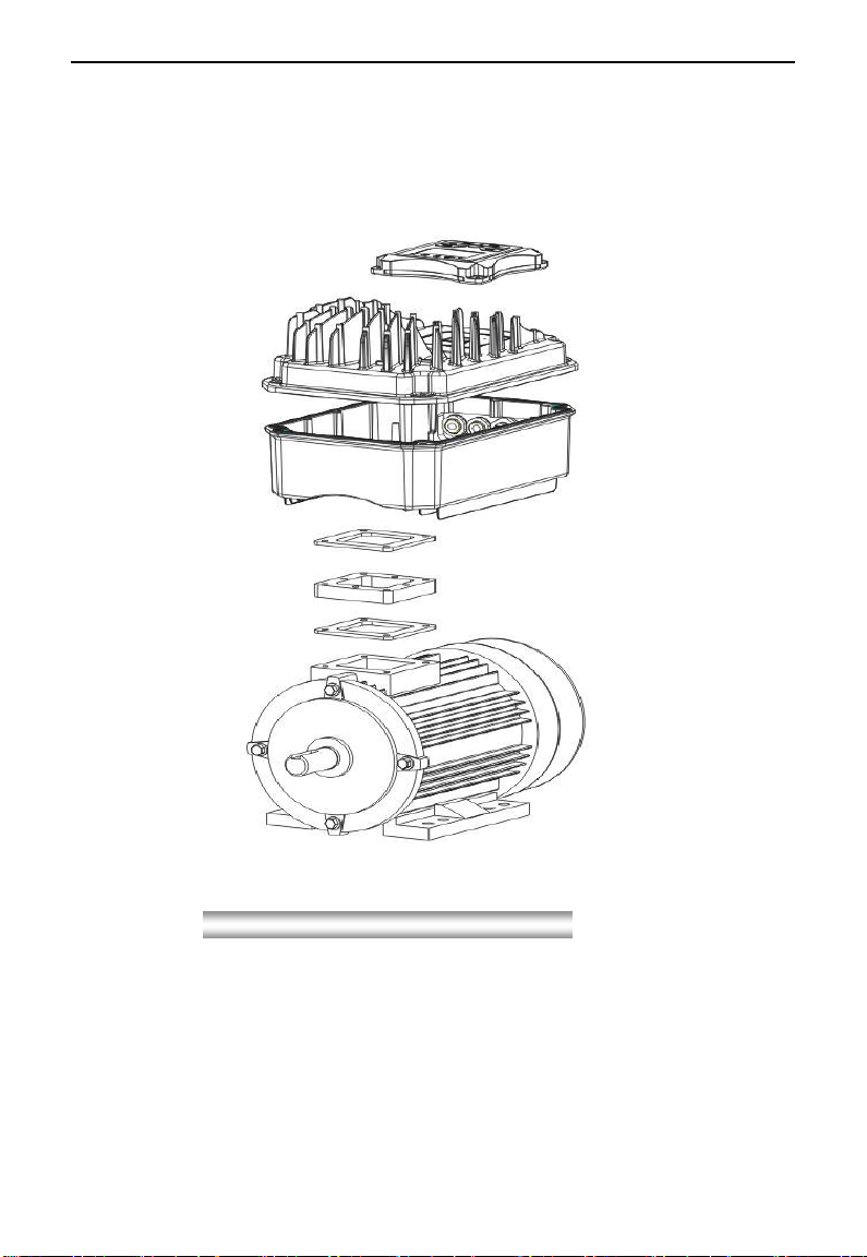
Exquisite structure design of aluminum casting housing, detachable cover structure and
convenient connection can realize perfect combination with motor. Take EM30-0075T3J2
for instance, the external appearance and structure are shown as below in Fig1-3.
Fig 1-3 Appearance and Structure
1.7 Designed Standards for Implementation
IEC/EN 61800-5-1: 2007 Adjustable speed electrical power drive systems safety
requirements.
IEC/EN 61800-3: 2004/+A1: 2012 Adjustable speed electrical power drive systems-Part 3:
EMC product standard including specific test methods.
1.8 Safe Instructions and Precautions
Please check the model in the nameplate of the inverter and the rated value of the
inverter. Please do not use the damaged inverter in transit.
Installation and application environment should be free of rain, drips, steam, dust
and oily dirt; without corrosive or flammable gases or liquids, metal particles or
metal powder. Environment temperature within the scope of -10℃~+40℃.
Please install inverter away from combustibles.
Do not drop anything into the inverter.
The reliability of inverters relies heavily on the temperature. The around temperature
increases by 10℃, inverter life will be halved. Because of the wrong installation or
fixing, the temperature of inverter will increase and inverter will be damaged.
Inverter is installed in a control cabinet, and smooth ventilation should be ensured
and inverter should be installed vertically. If there are several inverters in one
cabinet, in order to ensure ventilation, please install inverters side by side. If it is
necessary to install several inverters up and down, please add heat-insulation plate.

EM30
·7·
Inverter
M
Never touch the internal elements within 15 minutes after power off. Wait till it is
completely discharged.
Input terminals L1/R, L2/S and L3/T are connected to power supply of 400V/230V
(L1, L2 are connected to 230V) while output terminals U, V and W are connected to
motor.
Proper grounding should be ensured with grounding resistance not exceeding 4Ω;
separate grounding is required for motor and inverter. Grounding with series
connection is forbidden.
There should be separate wiring between control loop and power loop to avoid any
possible interference.
Signal line should not be too long(less than 3m) to avoid any increase with common
mode interference.
If circuit breaker or contactor needs to be connected between the drive and the motor,
be sure to operate these circuit breakers or contactor when the drive has no output,
to avoid damaging of drive.
Meet the environmental requirements of EM30 series technical specifications in
table 1-1.
Before using the drive, the insulation of the motors must be checked, especially, if it is
used for the first time or if it has been stored for a long time. This is to reduce the risk of
the drive from being damaged by the poor insulation of the motor.
Do not connect any varistor or capacitor to the output terminals of the drive, because the
drive‘s output voltage waveform is pulse wave, otherwise tripping or damaging of
components may occur; in addition, do not install circuit breaker or contactor at the
output side of the drive as shown in Fig 1-4.
Derating must be considered when the drive is installed at high altitude, greater than
1000m. This is because the cooling effect of drive is deteriorated due to the thin air,
as shown in Fig. 1-5 that indicates the relationship between the elevation and rated
current of the drive.
Fig 1-4 Capacitors are prohibited to be used.

·8·
Iout
(m)
100%
90%
80%
1000 2000 3000
EM30
Fig 1-5 Derating drive‘s output current with altitude
Never touch high-voltage terminals inside the inverter to avoid any electric shock.
Before inverter is powered on, please be sure that input voltage is correct.
Please do not connect input power supply onto U,V,W or terminals.
Please do not install inverter directly under sunshine, do not block up the cooling hole.
All safety covers should be well fixed before inverter is power connected, to avoid
any electric shock.
Only professional personnel are allowed for any maintenance, checking or
replacement of parts.
No live-line work is allowed.
1.9 Examination and Maintenance
1.9.1 Periodic checking
Cooling fan and wind channel should be cleaned regularly to check whether it is
normal; remove the dust accumulated in the inverter on a regular basis.
Check inverter‘s input and output wiring and wiring terminals regularly and check if
wirings are ageing.
Check whether screws on each terminals are fastened.
Check whether inverter is corrosive.
1.9.2 Storage
Please put the inverter in the packing case of manufacture.
If inverter is stored for long time, please charge the inverter every half a year to
prevent the electrolytic capacitors damaged. The charging time should be longer
than 5 hours.
1.9.3 Daily Maintenance
Environment temperature, humidity, dust and vibration would decrease the life of inverter.
Daily maintenance is necessary to inverters.
Daily inspecting:
Inspecting for noise of motor when it is working.
Inspecting for abnormal vibration of motor when it is working.
Inspecting for the installing environment of inverter.
Inspecting for the fan and inverter temperature.
Daily cleaning:
Keep the inverter clean. Clean surface dust of inverter to prevent dust, metal powder,
oily dirt and water from dropping into the inverter.
EM30
·9·
F100=0
Basic Parameters
User Password
Press FUN to return
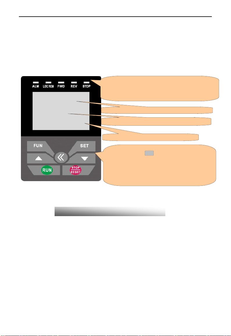
Fig.2-1 Operation Panels
5 indicators indicate working status. ALM blinks when fault occurs.
LOC/REM blinks in the remote-controlling status. FWD is ON when
rotating forward, REV is ON when rotating reversely, and STOP is always
ON when not running..
Function definition
Press ―FUN‖ for calling function code, and ―SET‖ for
original parameters. <<, ▲ and ▼keys can be used to
select function codes and parameters. Press ―SET‖ again to
confirm. In the mode of keypad control, ▲and▼keys can
also be used for dynamic speed control. ―Run‖ and
―Stop/Reset‖ keys control start and stop. Press
―Stop/Reset‖ key to reset inverter when in fault status.
Display and value of function code
Operation guidance
II. Keypad panel
The keypad function and indicator function for EM30 series will be showed in panel operating illustration.
2.1 Panel Illustration
The panel covers three sections: data display section, status indicating section and keypad operating section,
as shown in Fig. 2-1.
Instructions for operation panel:
1. Please select AC keypad (AC02: English keypad, 4-line LCD; AC04: Chinese keypad,
4-line LCD) for local control.
2. Local keypad panel can be introduced remotely. Select remote fittings if remote panel
is needed.

·10·
2.2 Keypad panel and installation bracket structure
Code A B C D H E
XX-X
115
115
102
102
21
Φ4.5
Pins 1 2 3 4 5 6 7 8
8 core
Reserved
5V
5V GND
5V GND
Signal 1
Signal 2
Signal 3
Signal 4
2.2.1 Structure Diagram
EM30
2.2.2 Structure Size (Unit: mm)
2.2.3 Port of Control Panel
Note: The interface of control board should be completely consistent with the interface of
the keypad panel, so the line sequence should also be the same.
EM30
·11·
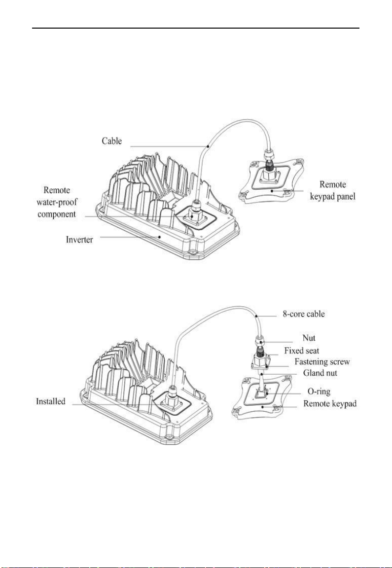
2.2.4 The remote-control components should reach the protection grade. The default
remote-control wire length is 1m. The length of remote-control wire can be custom-made
by users. If on the occasion of strong interference of occasion, or the length is longer than
3m, please put a magnetic ring on the wire to avoid interference. The figures of
remote-control components are showed as below
EM30
·12·
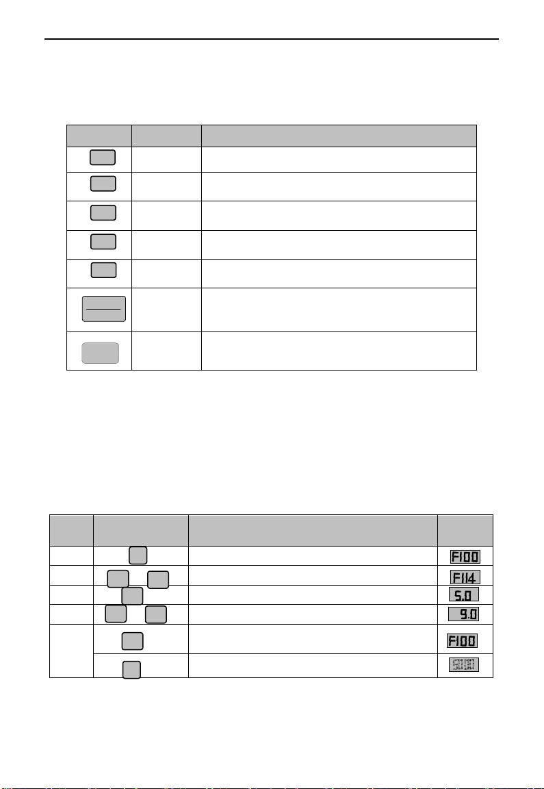
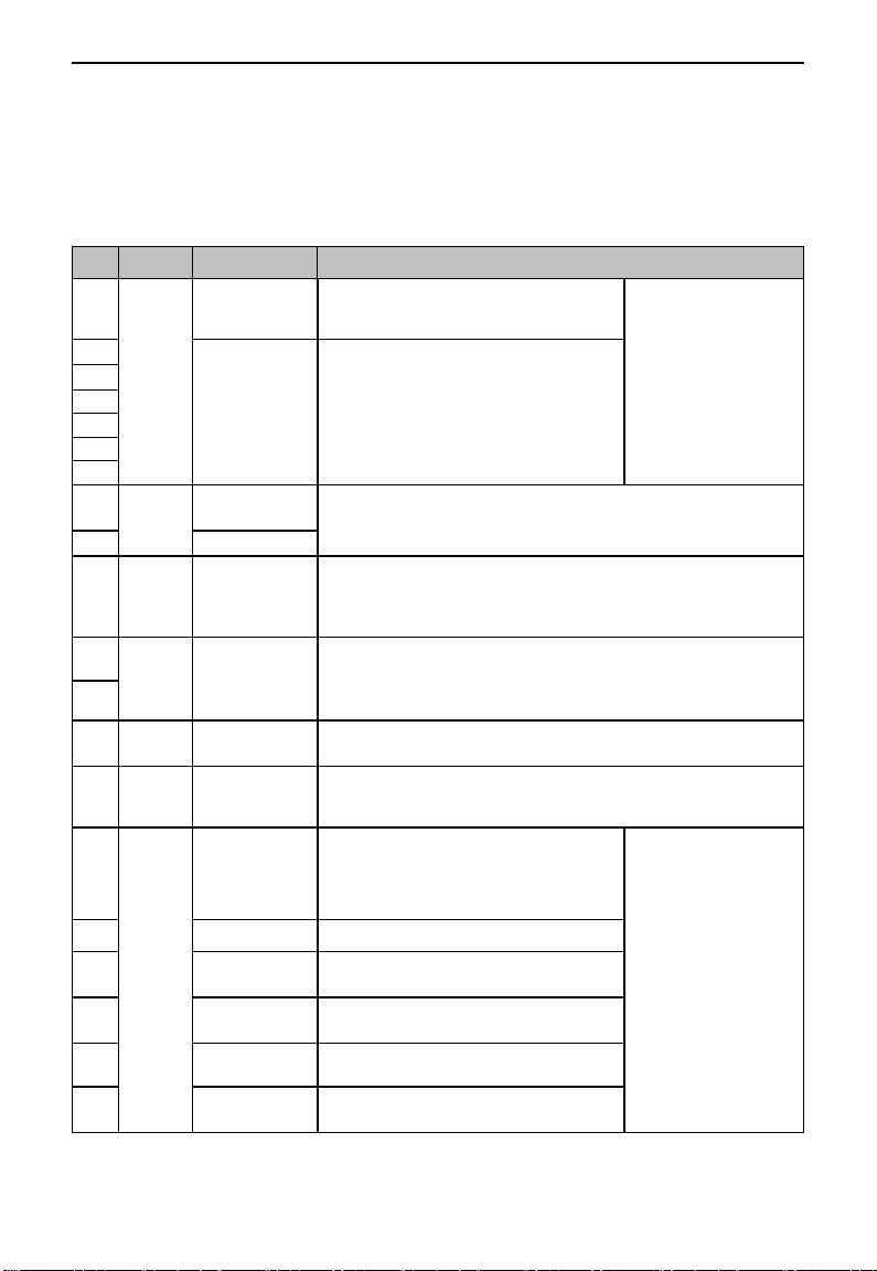
Keys
Names
Remarks
Fun
To call function code and switch over display mode.
Set
To call and save data.
Up
To increase data (speed control or setting parameters)
Down
To decrease data (speed control or setting parameters)
Run
To start inverter;
STOP
RESET
Stop or reset
To stop inverter; to reset in fault status;
<<
Shift key
Shift and displaying items switchover.
Steps
Keys
Operation
Display
1 Press ―Fun‖ key to display function code
2 Press ―Up‖ or ―Down‖ to select required function code
3 To read data set in the function code
4 To modify data
5
To display corresponding function code after saving the
set data
To display the current function code
Fun
▲
▼
or
Set
Set
Fun
▲
▼
or
FUN
SET
RUN
▲
▼
2.3 Panel Operating
All keys on the panel are available for user. Refer to Table 2-1 for their functions.
Table 2-1 Uses of Keys
2.4 Parameters Setting
This inverter has numerous function parameters, user can modify to effect different modes of operation
control. User needs to realize that if user sets password valid (F107=1), user‘s password must be entered
firstly if parameters need to set after power off or protection is effected, i.e., to call F100 as per the mode in
Table 2-2 and enter the correct code. User‘s password is invalid when leaving factory and user could set
corresponding parameters without entering password.
Table 2-2 Steps for Parameters Setting
The above-mentioned step should be operated when inverter is in stop status.
EM30
·13·
Group Name
Group
No.
Group Name
Group
No.
Basic Parameters
F1
Timing control and protection
function
F7
Run Control Mode
F2
Parameters of the motor
F8
Multi-functional
input/output terminal
F3
Communication parameters
F9
Analog signals and pulse of
input/output
F4
PID parameter setting
FA
Multi-stage speed
parameters
F5
Torque control parameters
FC
Subsidiary function
F6
Parameter display
H0
T1 T2
Time
Target Fre
①
①
②
③
②
③
Fig 2-2 Switch over in a Code Group or between Different Code-Groups
Currently showing
50.00
Press FUN key
F100 is displayed.
0 in F101 is
flashing.
F100
changes into
F101/F102/F103„
Press
▲
key
Press
▲or
▼
key
F101
changes into
F111/F121/F131„
Press
The first “1”in
F111 is flashing.
key
▲or
▼
F111
F211/F311/F411„
To set the function
code value, or
change it.
Press SET key
Press key
Press
key
changes into
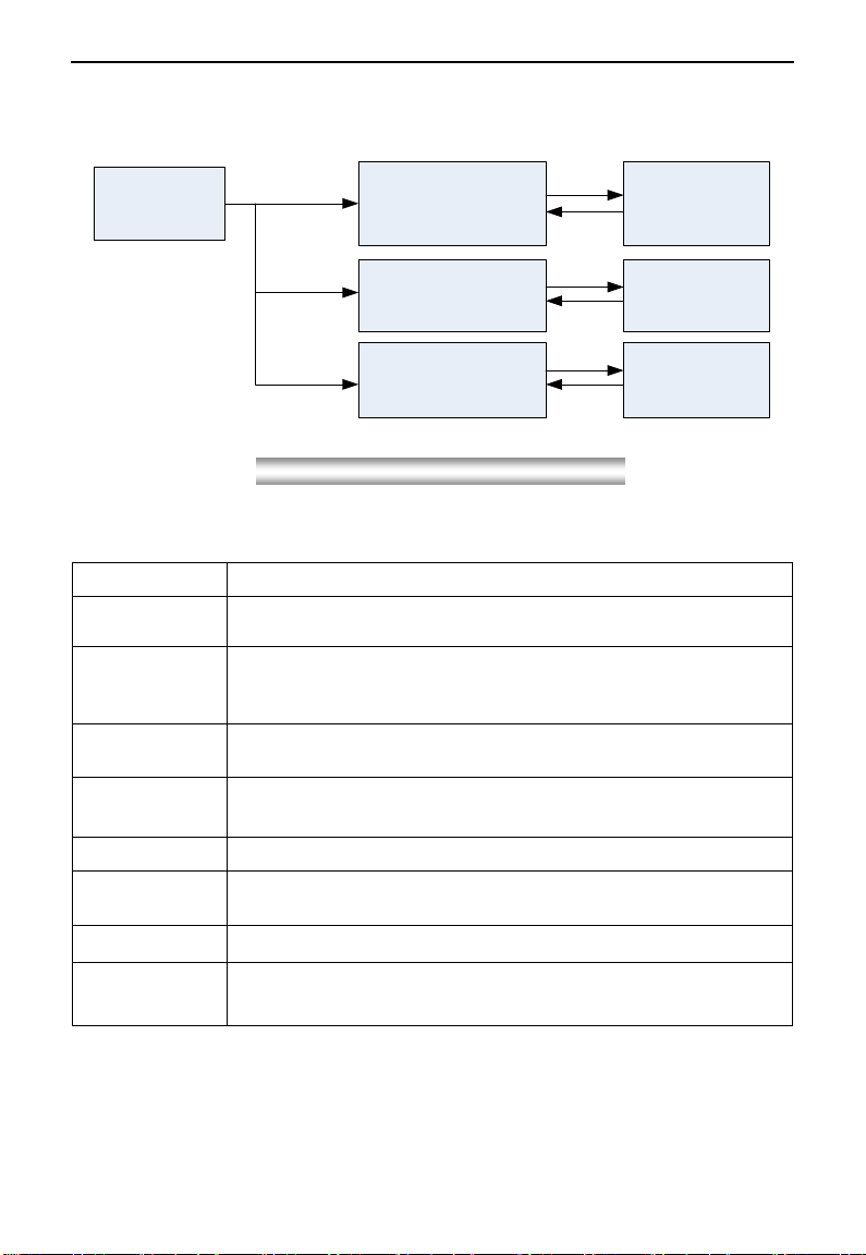
2.5 Function Codes Switchover in/between Code-Groups
It has more than 300 parameters (function codes) available to user, divided into 11 sections as indicated in Table 2-3.
Table 2-3 Function Code Partition
As parameters setting costs time due to numerous function codes, such function is specially designed as
―Function Code Switchover in a Code Group or between Two Code-Groups‖ so that parameters setting
become convenient and simple.
The operation of four-line LCD:
When function code shows F100 and the last ―0‖ in F100 is flashing, after pressing
―0‖ is flashing, then press << again, ―1‖ in F100 is flashing, the flashing value can be changed by
pressing ―▲‖/―▼‖ key.
key, the middle
·14·
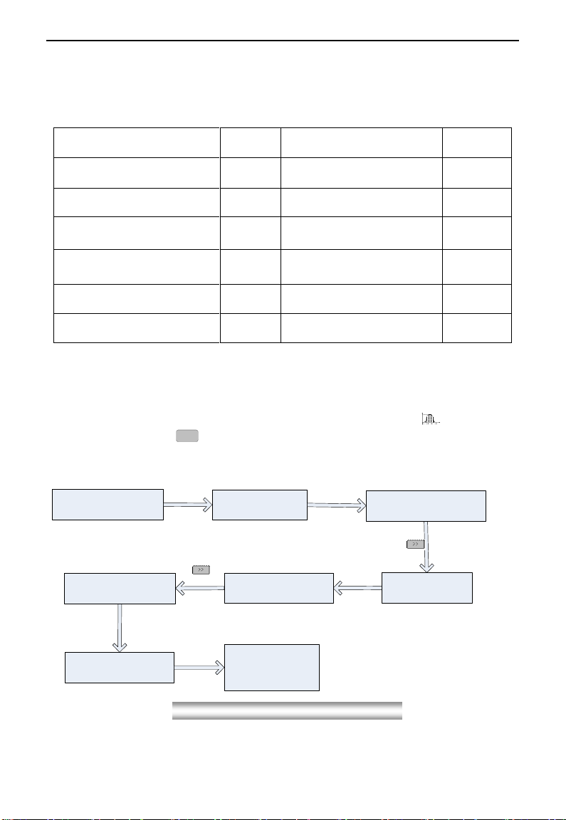
2.6 Operating instructions of 4-line LCD interface switch
Basic parameter
User password
F100= 0
Press FUN to return
Press
FUN
0.00 Hz
Current frequency
50.00 Hz
Target frequency
Stop status
Stop status
Long press SET
Loosen SET
Keypad version: 1.01
Current frequency
50.00 Hz
Target frequency
Basic parameter
User password
F100= 0
0~9999
Press
SET/FUN
Press
SET
0.00 Hz
Current frequency
0.00 rpm
Current rotate speed
F645=1
50.00 Hz
Current frequency
F645=1
1500 rpm
Current rotate speed
0.00 rpm
Current rotate speed
50.00 Hz
Target frequency
0.00 Hz
Current frequency
50.00 Hz
Target frequency
F645=1
F645=0
F132=0
F131=0
Fig 2-3 Operating flow chart of interface switch
Fig 2-4 Operating flow chart of status parameter display
2.6.1 Operating instructions of SET/FUN keys
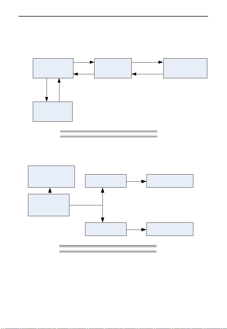
2.6.2 Operating instructions of inverter status display
EM30
EM30
·15·
0.00 Hz
Current frequency
50.00 Hz
Target frequency
Press
RUN
50.00 Hz
Current running frequency
1500 rpm
Current rotate speed
1300 rpm
Target rotate speed
1300 rpm
Current rotate speed
Long press
▼ key
Loosen
▼ key
49.00 Hz
Target frequency
538 V
DC bus voltage
49.50 Hz
Target frequency
538 V
DC bus voltage
Long press
▲ key
Loosen
▲ key
49.00 Hz
Current frequency
49.00 Hz
Current frequency
48.98 Hz
Target frequency
48.98 Hz
Current frequency
Long press
▼ key
Loosen
▼ key
Current status is
current rotate speed
Current status is
DC bus voltage
Current status is
current frequency
Items
Remarks
Power on….
It stands for power on process.
OC, OC1, OE, OL1,
OL2, OH, LU, PF0,
PF1, PCE
Fault code, indicating ―over-current OC‖, ―over-current OC1‖, ―over-voltage‖,
―inverter over-load‖, ―motor over-load‖ ―over-heat‖, ―under-voltage for input‖,
―phase loss for output‖, ―phase loss for input‖, and ―detuning fault‖ respectively.
AErr, EP, nP, Err5
Analog line disconnected, inverter under-load, pressure control, PID parameters
are set wrong,
ESP
During two-line/three line running mode, ―stop/reset‖ key is pressed or external
emergency stop terminal is closed, ESP will be displayed.
F152
Function code (parameter code).
10.00
Indicating inverter‘s current running frequency (or rotate speed) and parameter
setting values, etc.
50.00
Blinking in stopping status to display target frequency.
0.
Holding time when changing the running direction. When ―Stop‖ or ―Free Stop‖
command is executed, the holding time can be canceled
Fig 2-5 Operating flow chart of targ et frequency/rotate speed adjustments
2.6.3 Regulating target frequency/target rotate speed by UP/DOWN keys in running status
2.7 Panel Display
Table 2-4 Items and Remarks Displayed on the Panel
·16·
III. Installation & Connection
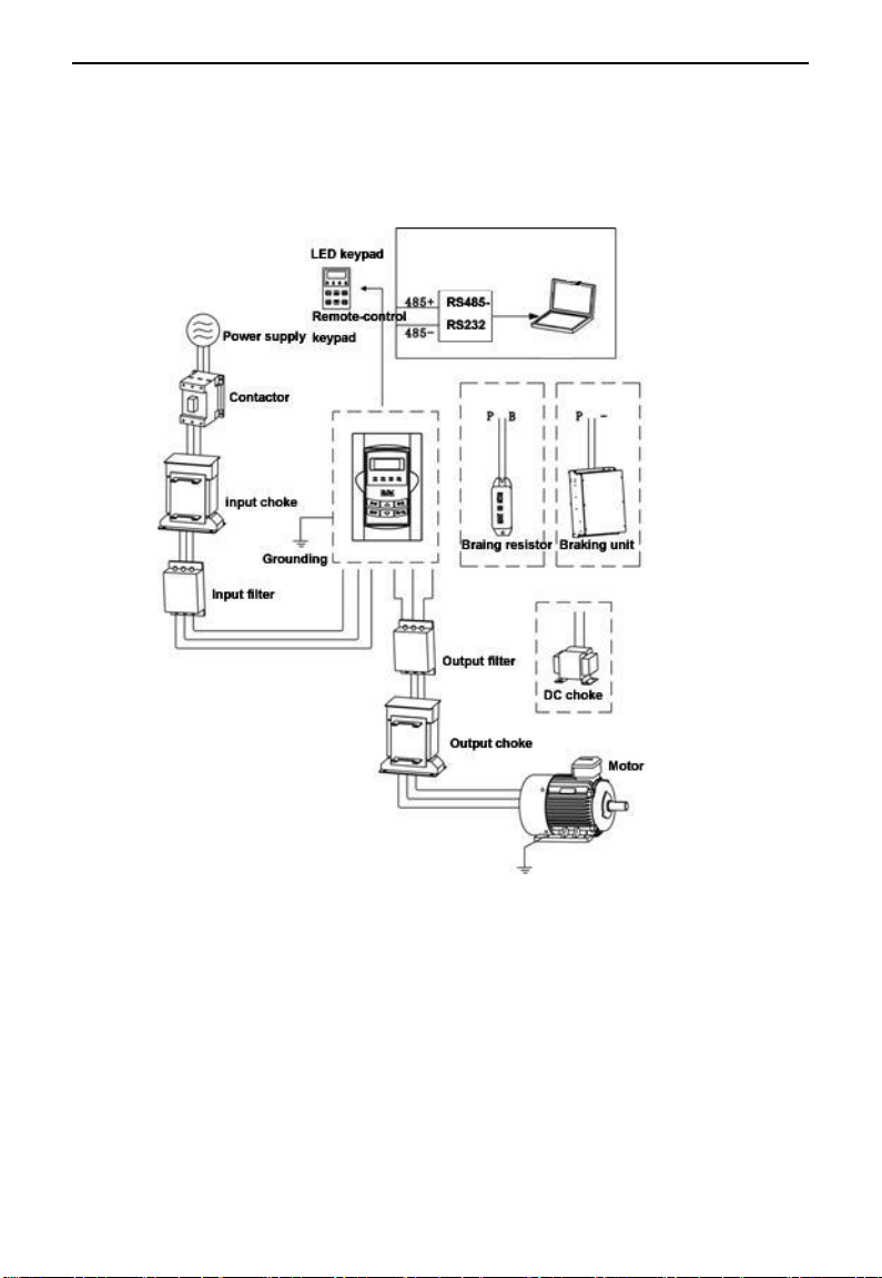
3.1 Periphery Wiring
EM30
Note: Braking unit is built in the T3 model of EM30 series, braking resistor is need only if the load
inertia is not too large.
·17·
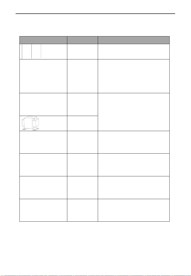
3.1.1 Accessories Graphic Illustration
Picture
Name
Description
Cables
Device to transfer the electronic signals
Breaker
Prevent from electric shock or protect the
power supply and the cables system from
over-current when short circuits occur.
(Please select the breaker with the function of
reducing high order harmonic and the rated
sensitive current to 1 one inverter should be
above 30mA)
Input choke
The device is used to improve the power
factor of the input side of the inverter and
control higher harmonic current.
DC choke
Input filter
Control the electromagnetic interference
generated from the inverter, please install
close to the input terminal side of the
inverter.
Braking unit or
resistor
Shorten the deceleration time.
Output choke
Control the interference from the output side
of the inverter, please install close to the
output terminal side of the inverter.
Output choke
Prolong the effective transmit distance of the
inverter to control the sudden high voltage
when switching on/off the IGBT of the
inverter.
Brake unit adopts EURA standard, the rest shows as below table:
EM30
·18·
3.2 Installation
Fig 3-1 Sketch map of inverter installed with motor
The Figure below shows that the inverter is installed with motor:
EM30
Note: Make sure effective ventilation space around drives.
EM30
·19·
GND
Braking resistor
Output
DC bus input
220V-240V AC
1-phase
input
GND
3-phase input 220V-240V AC Braking resistor
Output
DC bus input
DC bus
input
GND 3-phase input 380V-480V AC Braking resistor
Output
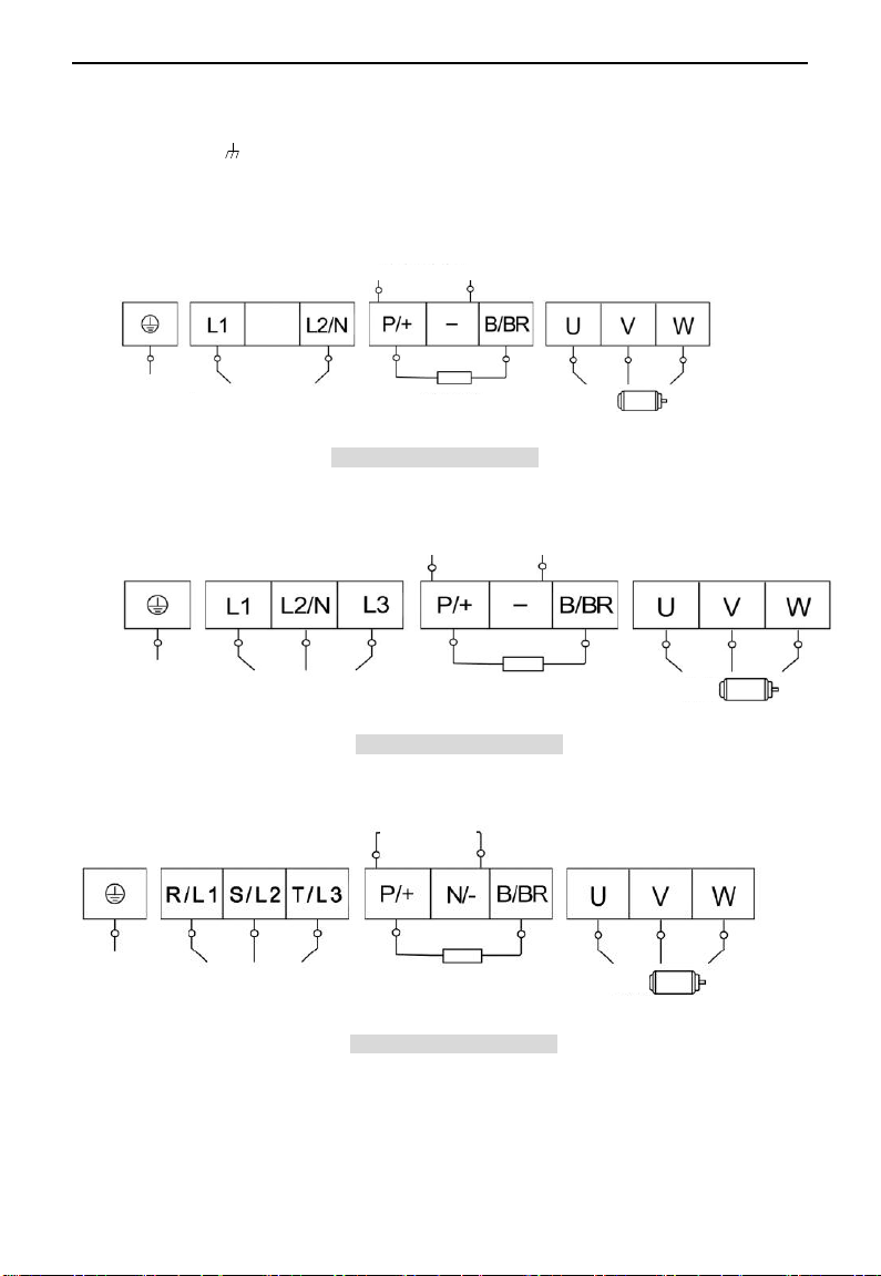
3.3 Connection
Connect R/L1, S/L2 and T/L3 terminals (L1 and L2/N terminals for single-phase) with power source
from network, /PE/E to earth, U, V and W terminals to motor.
Motor must be ground connected. Or else electrified motor causes interference.
Power terminals sketch of inverter with 1-phase 230V 0.4-2.2KW showed as below in Fig 3-2.
Fig 3-2 Power terminals sketch
Power terminals sketch of inverter with 3-phase 230V 0.4-5.5KW showed as below in Fig 3-3.
Fig 3-3 Power terminals sketch
Power terminals sketch of inverter with 3-phase 400V 0.75-15KW showed as below in Fig 3-4.
Fig 3-4 Power terminals sketch

·20·
Introduction of terminals of power loop
Terminals
Terminal
Marking
Terminal Function Description
Power Input
Terminal
R/L1, S/L2,
T/L3
Input terminals of three-phase 400V AC voltage, 1-phase 230V
connects to L1, L2/N, 3-phase 230V connects to L1, L2/N and L3.
Output Terminal
U, V, W
Inverter power output terminal, connected to motor.
Grounding
Terminal
MCCB1
Frequency-conversion switch
R
S
T
N
PE
M
M1
U
V
W
PN PE
T
S
MC1
OP6
R
OP1
CM
10V
AI1
GND
TC
TA
AO2
AO1
GND
AI2
F
A
S2
DO1
DO2
B-A+
24V
B
MCCB2
Linefrequency switch
MC2
FR1
Communication interface
MC1
S1
Power switch
MCCB3
HL1
MC1
HL2
FR1-NC
Run manually
S3
L2L1
MC3
Run automatically
FR2
FR1
L3
BZ
Pressure sensor
Frequency given
CM
M
M2
MC3MC4
FR2
+24V
MC1
KA1
MC2
MC4KA1
MC4
KA2
KA1
S4
MC3
S3
HL3
MC3
HL4
FR2-NC
Run manually
S5
MC1
Run automatically
MC2
KA2
MC4
MC3KA2
MC2
Inverter grounding terminal.
Rest Terminal
P/+, B/BR
External braking resistor terminals (Note: no Terminals P or B for
inverter without built-in braking unit).
P/+, N/-
Common DC bus terminals
Externally connected to braking unit
P/+ connected to input terminal ―P/+‖ or ―DC+‖ of braking unit,
N/- connected to input terminal of braking unit ―N/-‖ or ―DC-‖.
TA1
TB1
TC1
TA2
TB2
TC2 DO1
24V
CM
CM
DI1
DI2
DI3
DI4
DI5
DI6
10V
AI1
AI2
GND
AO1
AO2
GND
+5V
A+
B- CANH
CANL
Wiring for control loop as follows:
EM30
EM30
·21·
Type
Description
Function
DO1
Digit
Output
Multifunctional
output terminal 1
When the token function is valid, the value
between this terminal and CM is 0V; when
the inverter is stopped, the value is 24V.
The functions of output
terminals shall be defined
per manufacturer‘s value.
Their initial state can be
changed through
changing function codes.
TA1
Relay contact
TC is a common point, TB-TC is normally
closed contacts, and TA-TC is normally open
contacts. The contact capacity is
10A/125VAC、5A/250VAC、5A/30VDC.
TB1
TC1
TA2
TB2
TC2
AO1
Analog
output
Running
frequency
It is connected with frequency meter, speedometer or ammeter
externally, and its minus pole is connected with GND. See F423~F426
for details,.
AO2
Current output
10V
Analog
power
supply
Self contained
power supply
Internal 10V self-contained power supply of the inverter provides
power to the inverter. When used externally, it can only be used as the
power supply for voltage control signal, with current restricted below
20mA.
AI1
Analog
Input
Voltage / Current
Aanalog input
port
AI1:0~5V、0~10V、0~20Ma ;
AI2:0~5V、0~10V、0~20Ma
AI2
24V
Power
supply
Control power
supply
Power: 24±1.5V, grounding is CM; Current is restricted below 200mA
for external use.
CM
Common
port
Grounding of
control power
supply
The grounding of 24V power supply and other control signals.
DI1
Digital
input
control
terminal
Forward jogging
The functions of input
terminals shall be defined
per manufacturer‘s value.
Other functions can also
be defined by changing
function codes.
DI2
External scram
DI3
―FWD‖ Terminal
When this terminal is valid, inverter will run
forward.
DI4
―REV‖ Terminal
When this terminal is valid, inverter will run
reversely.
DI5
Reset
DI6
Free stop
Make this terminal valid during running can
realize free stop.
3.4 Functions of control terminals
The key to operate the inverter is to operate the control terminals correctly and flexibly. The control terminals
are not operated separately, and they should match corresponding settings of parameters. This chapter
describes basic functions of the control terminals. The users may operate the control terminals by combining
relevant contents hereafter about ―Defined Functions of the Terminals‖.
Table 3-2 Functions of Control Terminals
EM30
·22·
GND
Analog
grounding
Self-contained
Power supply
Ground
Ground terminal of external control signal (voltage control signal or
current source control signal) is also the ground of 10V power supply of
this inverter.
+5V
Power
supply
RS485 differential
signal positive
RS-485 differential signal positive power supply
A+
485
communic
ation
terminals
Positive polarity
of differential
signal
Standard: TIA/EIA-485(RS-485)
Communication protocol: MODBUS
Communication rate: 1200/2400/4800/9600/19200/38400/57600bps
B-
Negative polarity of
differential signal
K1
K2
K6
Inverter
control
board
DI1
DI2
DI6
CM
CM
DI6
DI1
External
controller
Inverter
control
board
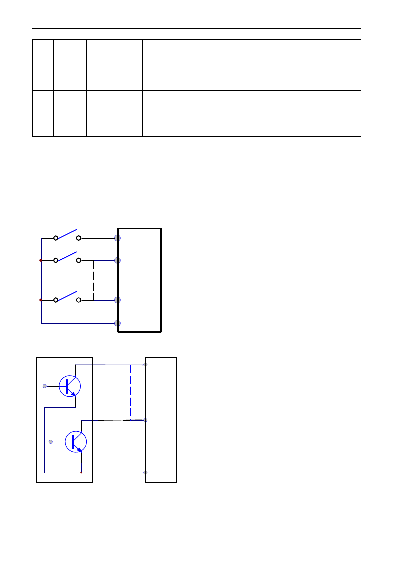
Wiring for digital input terminals:
Generally, shield cable is adopted and wiring distance should be as short as possible. When active signal is
adopted, it is necessary to take filter measures to prevent power supply interference. Mode of contact control
is recommended.
Digital input terminals are only connected by common source electrode (NPN mode) or by common drain
electrode (PNP mode). If NPN mode is adopted, please turn the toggle switch to the end of ―NPN‖.
Wiring for control terminals as follows:
1. Wiring for positive source electrode (NPN mode).
2. Wiring for active source electrode(NPN mode)
EM30
·23·
NPN
PNP
Fig 3-5 Toggle Switch J7
K1
K2
K6
DI1
DI2
DI6
CM
24V
Inverter
control
board
DI1
External
controller
DI6
CM
24V
Inverter
control
board
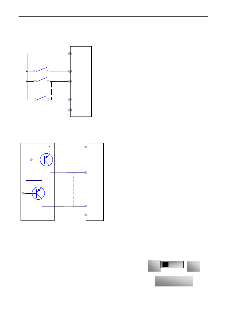
If digital input control terminals are connected by drain electrode, please turn the toggle switch to the
end of “PNP”. Wiring for control terminals as follows:
3. Wiring for positive drain electrode (PNP mode)
4. Wiring for active drain electrode (PNP mode)
Wiring by source electrode is a mode in common use at present. As factory defaults of control
terminals, wiring for control terminal is connected by source electrode, user should choose wiring
mode according to requirement.
Instructions of choosing NPN mode or PNP mode:
1. There is a toggle switch J7 near to control terminals. Please refer to
Fig 3-5.
2. When turning J7 to ―NPN‖, DI terminal is connected to CM.
When turning J7 to ―PNP‖, DI terminal is connected to 24V.
EM30
·24·
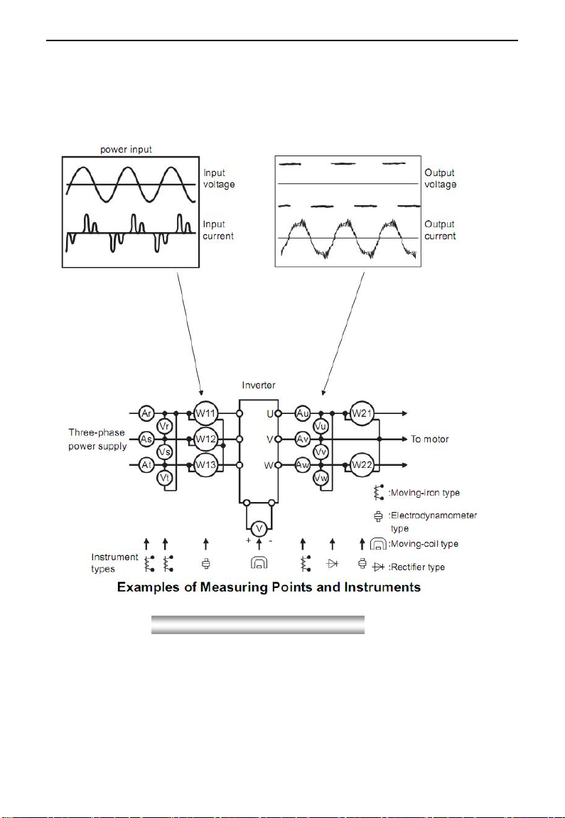
Fig 3-6 Measurement diagram
3.5 Measurement of main circuit(voltages, currents and powers)
Since the voltages and currents on the inverter power supply and output sides include high-frequency
components, measurement data depends on the instruments used and circuits measured. When commercial
frequency instruments are used for measurement, measure the following circuits(Fig3-6) with the
recommended instruments(Table 3-3).
·25·
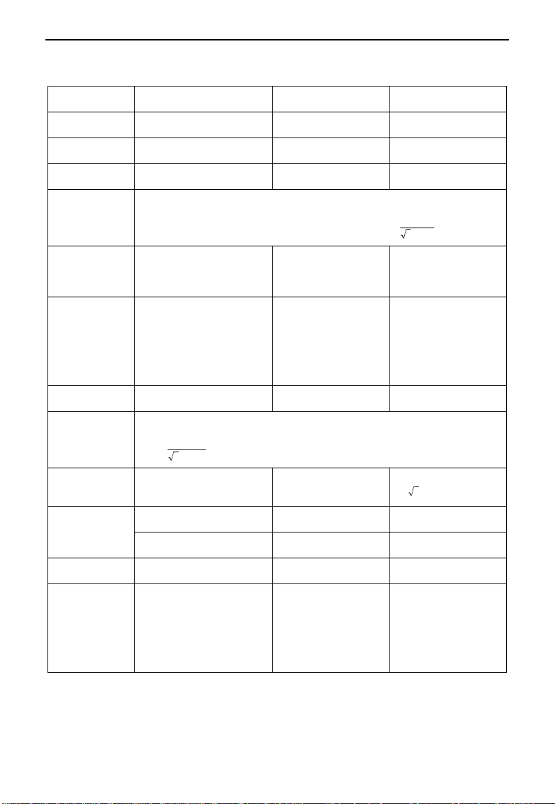
Table 3-3 Measuring instrucments
Item
Measuring Point
Measuring
Instrument
Remarks (Reference
Measurement Value)
Power supply
voltage V1
Across R-S,S-T, T-R
Moving-iron
type AC voltmeter
380±15%,
220V±15%
Power supply
side current I1
R, S, and T line currents
Moving-iron
type AC voltmeter
Power supply
side power P1
At R, S and T, and across
R-S, S-T and T-R
Electrodynamics type
single-phase wattmeter
P1=W11+W12+W13
(3-wattmeter method)
Power supply
side power
factor Pf1
Calculate after measuring power supply voltage, power supply side current and
power supply side power.[Three phase power supply]
%100
113
1
1
IV
P
Pf
Output side
voltage V2
Across U-V, V-W and W-U
Rectifier type AC
voltmeter (Moving-iron
type cannot measure)
Difference between the
phases is within ±1% of
the maximum output
voltage.
Output side
current I2
U, V and W line currents
Moving-iron type AC
Ammeter
Current should be equal
to or less than rated
inverter current.
Difference between the
phases is ±10% or
lower of the rated
inverter current.
Output side
power P2
U, V, W and U-V, V-W,W-U
Electrodynamics‘ type
single-phase wattmeter
P2 = W21 + W22
2-wattmeter method
Output side
power
factor Pf2
Calculate in similar manner to power supply side power factor:
%100
223
2
2
IV
P
Pf
DC bus voltage
(Rectifier
bridges output)
Across P+(P)and -(N)
Moving-coil type
(such as multi-meter)
DC voltage, the value is
12 V
Power supply of
control PCB
Across 10V-GND
Moving-coil type
(such as multi-meter)
DC10V±0.2V
Across 24V-CM
Moving-coil type
(such as multi-meter)
DC24V±1.5V
Analog output
AO1
Across AO1-GND
Moving-coil type
(such as multi-meter)
Approx. DC10V at max
frequency.
Alarm signal
Across TA/TC
Across TB/TC
Moving-coil type
(such as multi-meter)
<Normal> <Abnormal>
Across
TA/TC: Discontinuity
Continuity
Across
TB/TC: Continuity
Discontinuity
EM30

·26·
3.6 Overall Connection
Braking resistor
Braking unit
Reactor
NFB
3-phase input
AC 380V
50/60Hz
Multifunctional
input terminals
Multifunctional Relay Output
Multi-analog Signal(voltage)
Output1: 0~10V
Multi-analog Signal(current)
Output2:0~20mA
Multifunctional
Output Terminals
RS-485
Analog
signal
input
Main Loop Terminals
Shielded Cable
Control Loop Terminals
Note: Not for all power, specific please in kind prevail.
Refer to the figure below for overall connection sketch for EM30 series inverters. Wiring mode is available for
various terminals whereas not every terminal needs connection when applied
EM30
Note:
1. Please only connect power terminals L1/R and L2/S with power grid for single-phase inverters.
2. The contact capacity of inverter is 10A/125VAC, 5A/250VAC and 5A/30VDC.
 Loading...