

EURA DRIVES E800-0002 S2, E800-0011 S2, E800-0004 S2, E800-0015 S2, E800-0022 S2 Safety Instructions, Installation And Operating Manual
...
www.euradrives.eu
E800 – Rev.01 -EN- SOFT Rev. 2.04
© 2017 EURA Drives GmbH
Safety instructions Installation
& operating manual
FREQUENCY INVERTER
E800
0,2kW – 110kW (IP20)
ENGLISH

INDEX PAGE
1) Common installation- and safety rules for series E2000/3000 inverters 1
2) Product data / product range 10
3) Inverter mounting 15
4) Electrical connection of E2000 Inverters 16
5) Control-board – hardware and I/O channel configuration 23
6) Operating panel 29
7) Inverter parametrization 31
8) Parameter group 100: Basic parameter 32
9) Parameter group 200: Inverter control 38
10) Parameter group 300: Digital I/O configuration 43
11) Parametergruppe 400: Analogue I/O channel configuration 47
12) Parameter group 500: Fixed-frequency, automatic cycling frequencies 51
13) Parameter group 600: DC-Bake control / Aux. functions 52
14) Parameter group 700: Error handling and protection functions 55
15) Parameter group 800: Autotuning – Motor data programming 59
16) Parameter group 900: RS485 Hardware and interface parameters 61
17) Parameter group A00: PID controller parameter 62
19) Diagnostic functions 65
Rev. 01 -DE- 2015 KPP
Softwarerevision: 2.04
E800 – Rev.01 -D- SOFT Rev. 2.04
© 2015 EURADRIVES EUROPE GmbH
1) Common installation rules and safety information regarding EURA E800 inverters
1) Common installation- and safety rules for EURA DRIVES inverters, series
E800
IMPORTANT!!
This instruction manual explains rules for correct installation and safe operation of frequency
inverters, series E800 (denominated inverter, or drive in the following guidance). It is
mandatory to follow exactly, what reported in this instruction manual.
This instruction manual must be read and fully understood before
any action of installation or
placing in operation of the inverter.
Anybody, who operates the inverter, or the machine, equipped with inverter, must have access
to this operation manual, and must become familiar with drives technology, especially
regarding safety and warning issues
All instructions in this manual must be observed, to:
Guarantee safety for humans and machinery
Allow safe function and reliable operation
Permit approvals and certifications
Keep manufacturers warranty in force
Following pictograms are used in this instruction manual:
DANGER-WARNING-CAUTION
ATTENTION: Life or health of the user are
endangered or substantial damage to
property may occur.
ATTENTION – OBSERVE
Measures, necessary for safe and troublefree operation
E800 – Rev.01 -EN- SOFT Rev. 2.04
© 2015 EURADRIVES EUROPE GmbH
- 1 -
1) Common installation rules and safety information regarding EURA E800 inverters
Common:
DANGER
Frequency inverters operate with voltages, hazardous to
humans
Depending on inverters protection degree (IP class) and mounting
conditions, life parts may be accessible.
During heavy duty operation, and especially in case of malfunction,
parts/surfaces of inverters or accessory may reach dangerous
temperatures, which may result in personnel injury.
Inadmissible removal of covers or other parts of the inverter, improper
use, and not qualified mounting or operation may result in high risk for
personnel injury and/or machinery damage
All activity for mounting, cabling, placing into operation and operation
of the inverter must be done exclusively by proper educated and
trained people.
DANGER
The standards IEC 364 and/or CENELEC HD384, DIN VDE 0100 and
all other national safety standards are to observe.
Trained people has specific professional training, knowledge of all
relevant standards and safety rules and experience in application of
electrical/electronic drive systems.
These professionals are in condition to judge assigned duties, and
resulting risks.
Specified application of frequency inverters
.
The inverters, reported in this manual are components of
electrical/electronic drive systems and determinate for integration in
machines and plants only.
The E800 serves exclusively for the control and regulation of three
phase motors (asynchronus / synchronus motors)
The connection of loads, other than above listed, may result in
damage of the machinery, destruction of the inverter or connected
equipment, and serious risk of personnel injury.
DANGER
Observe specific standards and rules
It is not allowed, to place in operation the plant, before the
compliance with all standards of the machinery safety regulation
(89/392/EWG) and the EMC rules (89/336/EWG) has been checked
Inverters are conformal with low voltage directive (73/231/EWG).
Harmonized standards EN50178 (VDE160) and EN60439-1
(VDE0660, T. 500) are applied.
EURA DRIVES E800 is a product with limited availability (in sense of
IEC 61800-3). Frequency inverters may create high frequency noise,
in case the operator is responsible for proper countermeasures.
DANGER
E800 – Rev.01 -EN- SOFT Rev. 2.04
© 2015 EURADRIVES EUROPE GmbH
- 2 -
1) Common installation rules and safety information regarding EURA E800 inverters
Handling, transportation and storage
Inverter components may become damaged and insulating distances
may be reduced, as a result of improper transportation, handling or
storage of the drive.
DANGER
In this case, the inverter does not anymore comply with product
specific standards and rules, and it is not allowed to place it into
operation.
Therefore it is mandatory, to check the inverter for mechanical
integrity, before installation and operation.
The inverter may contain components, sensitive to electrostatic
discharge. Therefore avoid, touch components inside the drive.
It is recommended to store the inverter, using the original box.
If inverters are stored or out of use for more then one year, DC
capacitors may lose their capacity. Please contact the inverter
manufacturer for reformatting procedure
Installation of the inverter
DANGER
Frequency inverters must be installed in a proper cabinet.
Only fixed installation is permitted.
Follow all effective standards and rules for correct grounding!!
All minimum distances to other inverters or equipment in the cabinet
are to respect. Minimum distances are reported later on this manual.
Allow adequate air circulating, especially, in case of vertical mounting,
one on top of the other.
Use proper shielded cables, for inverter control signals and feed back
signals
Intrusion of dust, liquids, water, steam and aggressive gases must be
excluded
Attention on adequate heat exchange of the cabinet
Use of the inverter in explosion risky area is not allowed
E800 – Rev.01 -EN- SOFT Rev. 2.04
© 2015 EURADRIVES EUROPE GmbH
- 3 -
1) Common installation rules and safety information regarding EURA E800 inverters
Electrical wiring of frequency inverters
The entire plant must be disconnected from power, crosschecked for
loss of voltage and locked before
starting any work
DANGER HAZARDOUS
CAPACITOR CHARGE
The discharge time of the internal DC-LINK capacitors
may take up to 5 minutes, it is not allowed to open the
enclosures or to do any maintenance work during
discharge cycle!!
All connection terminals for control and feed-back are single insulated
in sense of EN50178.
In case of connection to external equipment with double insulation,
the user has to provide proper arrangement, to guarantee double
insulation in sense of EN50178 for the whole system
LVD – DOUBLE
INSULATON
GROUNDING
E800 inverters are designed for steady state installation, using fixed
wiring. It is not allowed, to use power plug or similar mobile
connection.
Depending on different EMC filter arrangements, the leakage current
to ground may exceed 3,5 mA. Therefore it is recommended to use
earth connection wiring, with minimum section of 10mm
2
(copper) or
use double wiring (in sense of EN50178)
All grounding connections must be as short as possible, all leading to
one common central point (star arrangement).
Long motor leads
A motor cable lenght, exceeding 30m, may result in over-voltage
spikes on the motor side. These peaks may damage the internal
insulation of the motor.
The use of motor chokes, sinus filter or dV/dt limiting filters may
prevent from risk of motor damage.
Generally it is recommended, to use inverter duty motors
In case of any doubt, please contact the manufacturer
All output filter components must have inverter
manufactures approval
E800 – Rev.01 -EN- SOFT Rev. 2.04
© 2015 EURADRIVES EUROPE GmbH
- 4 -
1) Common installation rules and safety information regarding EURA E800 inverters
Insulation testing
In case of insulation testing of the whole network, it is recommended
to disconnect the inverter and all optionally mounted filter
components. Some components, used inside the inverter may impact
measurement accuracy, o may become destroyed
All EURA inverters have to pass the insulation test, according to
EN15178, during the final test procedure on the production line.
Potential equalization
If components with no galvanic insulation are used and connected to
the inverter, proper measures are necessary, to guarantee potential
equalization.
E800 – Rev.01 -EN- SOFT Rev. 2.04
© 2015 EURADRIVES EUROPE GmbH
- 5 -
1) Common installation rules and safety information regarding EURA E800 inverters
DANGER OF FIRE
BURNS
Braking resistors
All kinetic energy of the system converts to heat, during braking cycle.
This energy dissipates in the braking resistor.
Improper dimensioning of the braking resistor or insufficient heat
exchange may result in high risk if fire
Also over-voltage on the input power supply my lead to high risk of
fire
Therefore all braking resistor must have two thermistors, series
connected, which contacts open in case of over-temperature,
disconnecting the whole power supply, on inverters input terminals
Braking resistors surface may become very hot, even
during normal operation. Therefore it is necessary to
mount the resistor in a save location, using proper
protecting cages.
IMPACT ON
DIFFERENTAL
CURRENT
BRAKERS
Differential current braker (FI)
The use of frequency inverters may delay or even inhibit the
trigger of differential current brakers.
For life protection, all plant with inverters must have following:
Input wiring protection: Fuses or automatic over-current braker
(Dimensioning: see tables).
Differential current protection: "All-sensitive" protectors
(braker), minimum requirement type „B“ , mounted on all
inverter power lines.
It is not permitted to connect other equipment on inverter power
lines.
For single phase inverters (230V class) the use of differential
current braker type "A" or "F" is allowed.
The trigger current of the differential current breaker depends on the
operating frequency, motor type, PWM frequency and the lenght of
the motor cable
It is recommended, to use differential current breaker with 300 mA
threshold (for industrial environment).
E800 – Rev.01 -EN- SOFT Rev. 2.04
© 2015 EURADRIVES EUROPE GmbH
- 6 -

1) Common installation rules and safety information regarding EURA E800 inverters
Basic rules for reliable and safe operation
-Proper dimensioning of the system (motor, inverter, mechanical elements).
-Check for correct inverters rated voltage, consider tolerances too
-Review all inverter and motor cabling, including correct terminal tightening torque
(torque values: see table).
-Use proper cable for all control wiring, separate control cable from power cable, min. 15 cm distance.
Use shielded cable for all control connections, exceeding 1 meter
-Twist wires to braking resistors or use shielded cables
-Shielded cables are recommended for motor connection too, especially with distances, exceeding 30
meters.
-Avoid earth loops, all earth connections should have large contact areas, all leading to one central
grounding point (star connected)
IMPORTANT FOR
SAVE INVERTER
OPERATION
One separate circuit breaker is recommended for each inverter –
allowing separate switch off of single inverters.
CHECK FOR PROPER INVERTER PROGRAMMING
Improper programming of the inverter may result in
unpredictable behavior of the system and subsequent high risk
of damage and/or personnel injury.
The inverter may be enabled for multiple automatic restart
attempts in case of fault – delayed restart is possible.
Unpredictable systems reactions may become the result of
internal inverter defects.
The inverter may ignore commands, speed, STOP instructions,
or signals originated from external components.
The braking function of the inverter may fail.
Depending on the application, external safety components,
working independently from the inverter, are required, to
guarantee the safety of the whole system
Inverter protection-functions
Although the inverter is equipped with intelligent protections functions,
the repetitive triggering of those functions may result in inverter
damage.
The inverter is protected against output short circuit and earth fault,
each displayed by a specific code on the display.
Repetitive earth faults and short circuits may damage the power
stage of the inverter.
The motor must be fixed connected, in case, where interruption of the
motor line is required (for safety reason), the circuit should open/close
with inverter in STOP condition only (final stage disabled).
It is recommended, to keep the inverter powered on at all time, if for
application reason repetitive power on cycling is required, it should
not exceed one cycles every 5 minutes – otherwise contact the
manufacturer.
E800 – Rev.01 -EN- SOFT Rev. 2.04
© 2015 EURADRIVES EUROPE GmbH
- 7 -
1) Common installation rules and safety information regarding EURA E800 inverters
Power-grid specification:
The inverter is build for symmetric three phase power supply
systems, with voltage phase to earth/neutral not exceeding 300V.
A transformer can be used for adaptation to higher voltages.
For single phase inverters the maximum input voltage is 240V +15%,
400V class thee phase inverters can work up to 460V +15%.
Contact the inverter manufacturer, before connecting to unbalanced,
floating, or unsymmetrical power systems.
Power supply – short circuit capability
Input chokes (Uk=4%) are recommended to connect the inverter on a
power grid with high short circuit capability, this especially for
continuous operation.
If the power supply capability exceeds by 20 times the inverter power,
the use of chokes is mandatory.
Measurements on inverter input and output:
Current and voltage may have no sinus shaped waveform on inverters input/output side.
If improper testing instruments are used, the result may become inaccurate, or in worst case, the
inverter and/or the test instrument may become destroyed.
On input side, the current waveform is composed by fundamental and harmonics, while on output side
the voltage waveform is PWM modulated.
The used instruments must be able to handle the various signal waveforms. For si mple
measurements, a high quality moving iron instrument could be suitable.
FOR ANY QUESTION –
CONTACT THE
MANUFACTURER
The inverter manufacturer must be contacted in
case of any question, regarding this
safety/instruction manual, or if some parts have
not been fully understood.
Please ask before installing or placing on
operation the system.
This is mandatory, to avoid any risk for
machinery damage and/or personnel injury.
E800 – Rev.01 -EN- SOFT Rev. 2.04
© 2015 EURADRIVES EUROPE GmbH
- 8 -

1) Common installation rules and safety information regarding EURA E800 inverters
EMC: Basics and recommendations for installation
The E800 series inverters are electrical devices, designed for installation in industrial area.
E800 inverters are not designed to work stand alone, these inverters are considered as part of a
complex system, for this reason, no separate EMC marking is applyed on the in verter.
The machine builder / system integrator is obligated to prove the compliance with actual EMC
standards for the whole system.
Normally, the inverter integrated EMC filters are sufficient, to meet the actual EMC limits (this has
been confirmed by measurements, performed by independent body).
Inverters E800 are designed for use in "second environment", (in sense of EN61800-3).
This means installation in industrial area, where power supply is done via separate
transformer.
Fore installation in "first environment" (residential area – public low voltage power grid),
additional filter components may become necessary, to meet EMC rules.
EMC - adequate installation
Mounting in metal cabinet, if possible, the cabinet should be divided into power and control area, using
metal shielding barrier, or similar
Connect all metal parts, grounding cables, cable shields on one central point, using the blank
mounting plate as contact area.
Use 10mm
2
cables for potential equalization, "star" connected on one central point.
Please consider, that inverters and filters may have more than 3,5 mA leakage current, therefore use
proper earthing / grounding conductors:
Grounding conductor min. 10 mm² (copper)
Grounding connection with separate monitoring system, which disconnects
automatically in case of fault.
Dual grounding, using separate cable and terminals.
Use shielded cables, wherever possible, with copper mesh, common cable steel protection is not
working as shield.
Connect shields on large blank areas with potential equalization bars. Use special cable gl ands, with
integrated contact brushes.
It is not allowed to extend cable shield, using single wire.
Mount all external filter components as close as possible to the noise source (inverter) – get perfect
contact, mounting directly on the blank cabinet plate.
Keep all wiring as short as possible, separate different networks, min. 15 cm distance.
Different networks are: power supply, motor cable (incl. brake resistor), low voltage control wiring
(control signals, feed back, data line).
Twist all unshielded cables
Unused wires in cables should be connected to ground
E800 – Rev.01 -EN- SOFT Rev. 2.04
© 2015 EURADRIVES EUROPE GmbH
- 9 -

1) Common installation rules and safety information regarding EURA E800 inverters
E800 – Rev.01 -EN- SOFT Rev. 2.04
© 2015 EURADRIVES EUROPE GmbH
- 10 -
Inverters with UL mark: Additional information
Following information are valid for inverters, designed for use in co untries, which require UL approval.
All information below must be available to all w ho are responsible for commercialization, installation and place in
operation.
UL Standards
The UL/cUL mark applies to products in the United States and Canada and it means that U L has performed product testing and evaluation
and determined that their stringent standards for product safety have been met. For a product to receive UL certification, all components
inside that product must also receive UL certification.
UL Standards Compliance
This drive has been tested in accordance with UL standard UL508C, File No. E363934 and complies with UL requirements.
To ensure continued compliance when using this drive in combination with other equipment, meet the following conditions:
1)Do not install the drive to an area gr eater than pollution severity 2 (UL standard)
2)Installation and operating instructions shall be provided with each device.
The following markings shall appear in one of the following locations: shipped separately with the device; on a separable, self-adhesive
permanent label that is shipped with the device; or anywhere on the device itself.
a) Designation markings for each wiring diagram;
b) Markings for proper wiring connections.
c) “Maximum Surrounding Air Temperature 40ºC. ” or equivalent;
d) “Solid State motor overload protection reacts when reaches 150% of FLA” or equivalent;
e) “Install device in pollution degree 2 environment.” or equivalent;
f) For Models of Frame Size(E800-0007T3UBR;E800-0011T3 UBR;E800-00 15T3 UBR;E800-0022T3UBR): “Suitable For Use On A Circuit
Capable Of Delivering Not More Than 5,000 rms Symmetrical Amperes, 480 Volts Maximum When Protected By made by COOPER
BUSSMANN L L C Class T Fuse: JJS-15.” or equivalent.
For Models of Frame Size (E800-0030T3UBR;E800-0037T3UBR;E800-0040T3UBR): “Suitable For Use On A Circuit Capable Of Delivering
Not More Than 5,000 rms Symmetrical Amperes, 480 Volts Maximum When Protected By made by COOPER BUSSMANN L L C Class T
Fuse: JJS-25.” or equivalent.
For Models of Frame Size (E800-0055T3UBR;E800-0075T3UBR): “Suitable For Use On A Circuit Capable Of Delivering Not More Than
5,000 rms Symmetrical Amperes, 480 Volts Maximum When Protected By made by COOPER BUSSMANN L L C Class T Fuse: JJS-35.” or
equivalent..
g) “Integral solid state short circui t protection does not provide branch circuit protection. Branch circuit protection must be provided in
accordance with the National Electrical Code and any additional local codes” or the equivalent;
h) “CAUTION – Risk of Electric Shock” should be provided, followed by instructions to discharge the Bus Capacitor or indicating the time
required (5 minutes) for Bus Capacitor to discharge to a level below 50 Vdc;
i) “Drives have no provision for motor over temperature protection” or equivalent;
j) For used in Canada only: “TRANSIENT SURGE SUPPRESSION SHALL BE I NSTALLED ON THE LINE SIDE OF THIS
EQUIPMENT AND SHALL BE RATED __480_ V (PHASE TO GROUND), 480 V (PHASE TO PHASE), SUITABLE FOR
OVERVOLTAGE CATEGORY _III_, AND SHALL PROVIDE PROTECTION FOR A RATED IMPULSE WITHSTAND VOLTAGE PEAK
OF _6 kV” or equivalent.
Field Wiring Terminal Markings – Wiring terminals shall be marked to indicate the proper connections for power supply and load, or a
wiring diagram coded to the terminal marking shall be securely attached to the device:
a.“Use 60/75°C CU wire” or equivalent;
b. Required wire torque, type and range listed: see chapter 4) Empfohlene Leitungsquerschnitte – Sicherungen Leistungsklemmen
Grounding – The wire connector intended for ground connection for field installed equipment, shall be clearily identified such as being
marked “G”, “GRD”, “Ground”, “Grounding”, or equivalent or with the grounding symbol (IEC 417, Symbol 5019).
Tightening torque and wire section for field grounding wiring are ma rked adjacent to the terminal or on the wiring diagram.
2) Product data / Product range
2) Product data / product range
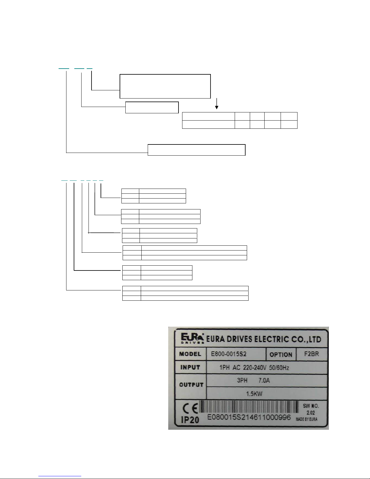
Product naming convention
E800 – 0007 S2
Options identifier
D F2 Y K B R
Nameplate
The adjacent picture shows a typical nameplate of a
series E800, single phase, 230V 1,5 kW inverter, 7A
rated current, including following options: F1
(MODBUS), B (Brake-chopper) R (integrated EMCFilter)
Power - Code 0002 0004 0007 ……
Motor power (kW) 0.2 0.4 0.75 ……
Codierung-siehe Typenübersicht
Power supply:
S2 Singlephase 220/230 VAC +/-15%
T3 Threephase 400/460 VAC +/-15%
Motor rated power
Typ – Serial - Inverter class (E800)
EMC Filter:
--- No filter
R Filter integrated
Brake chopper
--- No Chopper
B Chopper integrated
Keypad / potentiometer
--- No potentiometer
K Potentiometer
Mechanical concept
--- Wallmount (inside cabinet)
D Inverter integrated in cabinet
Keypad concept
--- Integrated
Y Removable
Fieldbus
--- No fieldbus
F2 MODBUS
E800 – Rev.01 -EN- SOFT Rev. 2.04
© 2015 EURADRIVES EUROPE GmbH
- 10 -
2) Product data / Product range
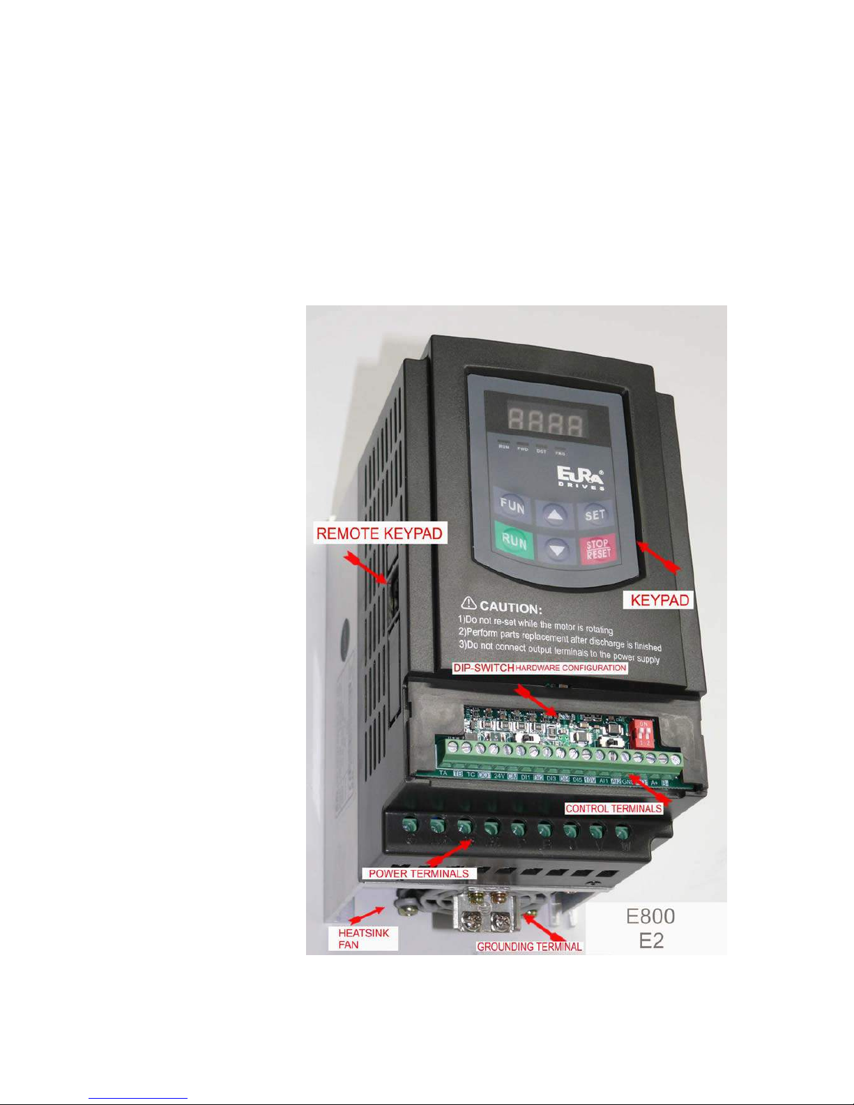
Mechanical construction
There are two different basic concepts:
Inverter with power range from 0,75 to 22 kW: POLYCARBONATE enclosure, build on a constructional base (heatsink) with
the keypad integrated on the cover (not removable) – framesize E1 – E6
Inverter with power range from 18,5 to 90 kW: Steel panel, power and control terminals inside, with the keypad integrated in
the cover and removable - framesize C3 – C6
Appearance of an E800 - Size E2 inverter
E800 – Rev.01 -EN- SOFT Rev. 2.04
© 2015 EURADRIVES EUROPE GmbH
- 11 -
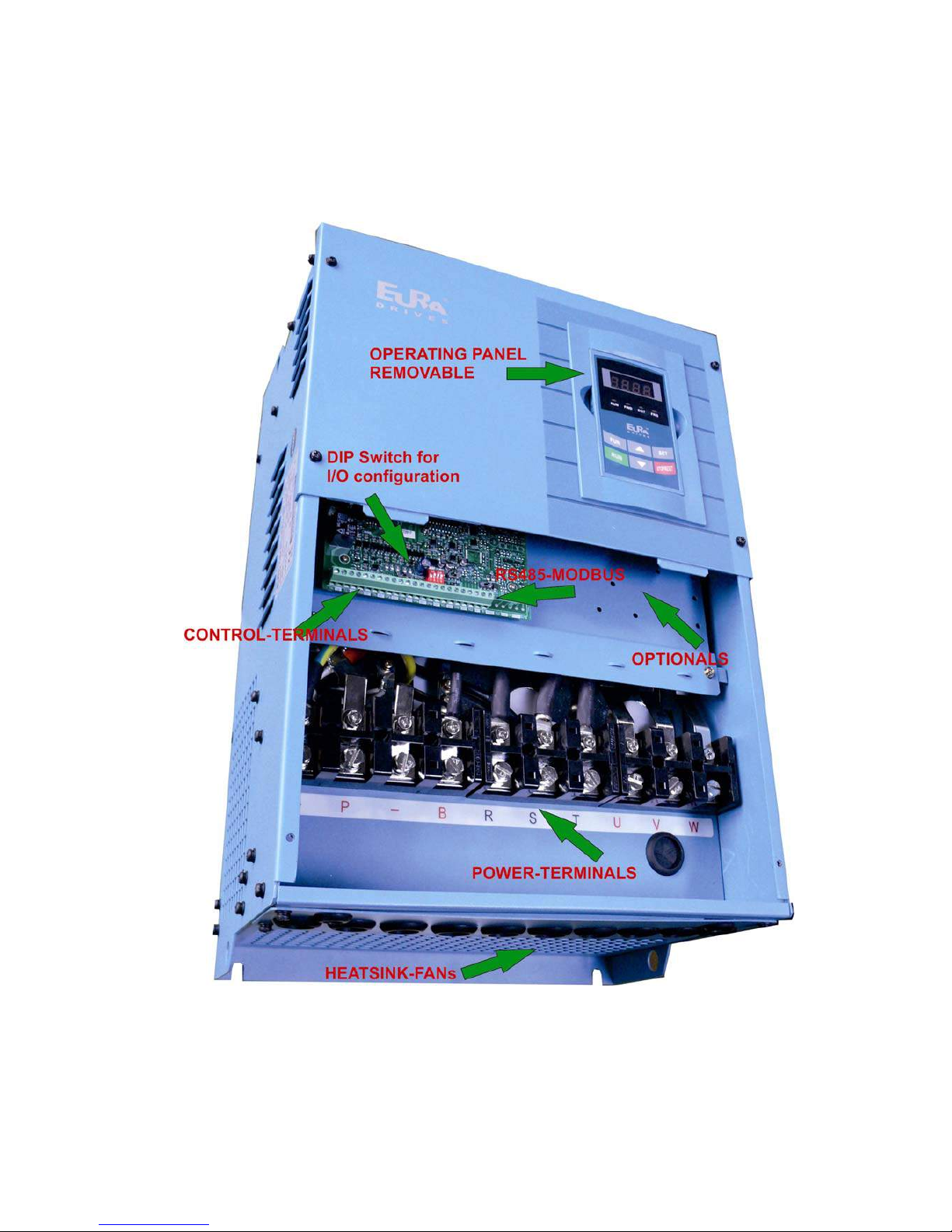
2) Product data / Product range
Appearance of an E800 - Size E8 inverter
E800 – Rev.01 -EN- SOFT Rev. 2.04
© 2015 EURADRIVES EUROPE GmbH
- 12 -

2) Product data / Product range
T echnical data – inverter series E800
Rated voltage 3-Phase 380…460V - 3 Ph. 220...240V - 1Ph. 220...240V - Tol. +/- 15%
Input frequency 44….67 Hz
Power supply
EMC filter Integrated for 2. Environment – C3 (up to 90 kW)
Output voltage 0……...U-input
Output frequency 0……...650 Hz
Resolution of output frequency 0,01 Hz
Output
Overload capability 120% - 60 sec. / 10 Min
PWM control-modes
V/Hz - Mode
Permanentmagnet Synchronmotor control (Software option)
PWM frequency 0,8…10 kHz
V/Hz characteristic Linear, quadratic, and user-programmable curve
Torque boost Automatic / Manual
Motor data input Manual input / intelligent AUTOTUNING function
DC-Brake Freq. threshold, duration and intensity programmable
Control mode
Brake chopper Integrated chopper transistor (Brake resistors – see product table)
Display
7 Segment LED display -4- digit For programming and visualization of different operating parameters
Inverter control - Start/Stop To configure: terminals / operation panel / serial link
Digital control inputs 8 (5) digital inputs (HIGH/LOW configurable), pulse input
Speed reference signal
Potentiometer (on operating panel / Extern), analogue input (terminals) ,
operating panel keys, pulse input, serial link
Reference analogue channels
2 Analogue channels 12 BIT 0…10V, 0..(4)20 mA (with programmable offset,
gain – to concatenate mathematically each other)
Analogue outputs
2 (1) analogue output channels, both programmable in gain, different
functions to assign (0…10V, 0..20 mA)
Digitale outputs 2 (1) digital outputs (different functions to assign)
Relays output 1 switchover contact 5 A 230 V (programmable for different functions)
Interface Serial link (MODBUS – ASCI/RTU)
Jog mode, 12V / 50 mA auxiliary power supply on terminals
PI-control
I/O Channels,
control functions
Special function - control options
Fixed frequency control "Catch on the fly function", AUTORESET/RESTART
functions
Overvoltage, Undervoltage
Overcurrent, Overload, Motor-Overload, Output-short
Electrical protection functions
Phaseloss, Motor-Phase imbalance
Protection
functions, incl.
fault memory
Thermal protection functions
Heatsink overtemperature – Motor overtemperature (PTC/KLIXON),
Motor I
2
xt
Operating panel Remote keypad / programming tool
Brake resistors High power resistors for heavy duty operation
Filter / chokes PFC chokes – dv/dt limiting output filter - sinusfilter
Optionals
PC-Link Software (via MODBUS) Special tool for programming, control and diagnostic (parameter set memory)
Protection IP20 – IP21 (optional)
Operating temperature -10……+50 °C
Humidity Max. 90 % not condensing, no corrosion
Elavation 1000 m - 1% derating / 100m above
Environmental
conditions
Vibration Max. 0,5 g
0,2……400 kW
Power range
EMC EN61800-3(2004)
Standards
Safety EN61800-5-1 2003
E800 – Rev.01 -EN- SOFT Rev. 2.04
© 2015 EURADRIVES EUROPE GmbH
- 13 -
2) Product data / Product range
E800 – Rev.01 -EN- SOFT Rev. 2.04
© 2015 EURADRIVES EUROPE GmbH
- 14 -
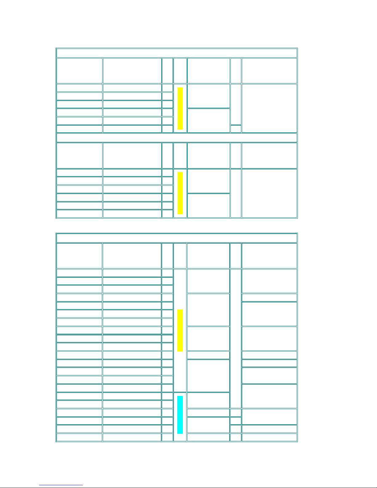
Product range - framesize
Inverter 230V – 1 Phase
Model
Rated power / Current
Size
Enclosure
Dimensions
(wxHxD - mm)
BR.Chopp.
Minimum brake
resistor value
E800-0002 S2 0,2 kW - 1,5A E1
E800-0004 S2 0,4 kW - 2,5A E1
E800-0007 S2 0,75 kW - 4,5A E1
80x138x135
E800-0011 S2 1,1 kW - 7A E2
E800-0015 S2 1,5 kW - 7A E2
INTEGRATED
E800-0022 S2 2,2 kW - 10A E2
POLYCARBONATE
106x180x150
80 Ohm / 100W
Inverter 230V – 3 Phase
Model
Rated power / Current
Size
Enclosure
Dimensions
(WxHxD - mm)
BR.Chopp.
Minimum brake
resistor value
E800-0002 S2 0,2 kW - 1,5A E1
E800-0004 S2 0,4 kW - 2,5A E1
E800-0007 S2 0,75 kW - 4,5A E1
80x138x135
E800-0011 S2 1,1 kW - 7A E2
E800-0015 S2 1,5 kW - 7A E2
E800-0022 S2 2,2 kW - 10A E2
POLYCARBONATE
106x180x150
INTEGRIERT
80 Ohm / 100W
Inverter 400V – 3 Phase
Model
Rated power / Current
Size
Enclosure
Dimensions
(WxHxD - mm)
BR.Chopp.
Minimum brake
resistor value
E800-0002 T3 0,2 kW – 0,6 A E1
E800-0004 T3 0,4 kW – 1 A E1
E800-0005 T3 0,55 kW – 1,5 A E1
80x138x135 200 Ohm / 100W
E800-0007 T3 0,75 kW - 2 A E2 150 Ohm / 100W
E800-0011 T3 1,1 kW – 3 A E2
E800-0015 T3 1,5 kW – 4 A
E2
E800-0022 T3 2,2 kW - 6,5 A
E2
106x180x150
100 Ohm / 100W
E800-0037 T3 3,0 kW - 8 A
E4
E800-0040 T3 4,0 kW - 9 A
E4
E800-0055 T3 5,5 kW - 12 A
E4
138x235x152 80 Ohm / 300W
E800-0075 T3 7,5 kW - 17 A
E5
156x265x170 80 Ohm / 600W
E800-0110 T3 11 kW - 23 A
E5
50 Ohm / 600W
E800-0150 T3 15 kW - 32 A
E6
E800-0185 T3R 18,5 kW - 38 A
E6
30 Ohm / 1000W
E800-0220 T3R 22 kW - 44 A
E6
POLYCARBONATE
205x340x196
E800-0300 T3R 30 kW - 60 A
C3
E800-0370 T3R 37 kW - 75 A
C3
270x435x235
INTEGRATED
20 Ohm / 1500W
E800-0450 T3R 45 kW - 90 A
C4
315x480x235
E800-0550 T3R 55 kW - 110 A
C5
15 Ohm / 2000W
E800-0750 T3R 75 kW - 150 A
C5
369x555x265
10 Ohm / 3000W
E800-0900 T3R 90 kW - 180 A
C6
SHEET METAL
410x630x300 8 Ohm / 10000W
3) Inverter mounting
3) Inverter mounting
Please read all, what reported on chapter 1) Common installation- and safety rules for EURA DRIVES inverters, series
E800 before proceeding with inverter mounting, cabinet wiring, and putting the system into service.
Mounting in cabinet
Accordingly to the protection degree class (IP20/21), the inverter must be placed in a proper cabinet.
The inverter should be mounted vertically, using all available mounting holes.
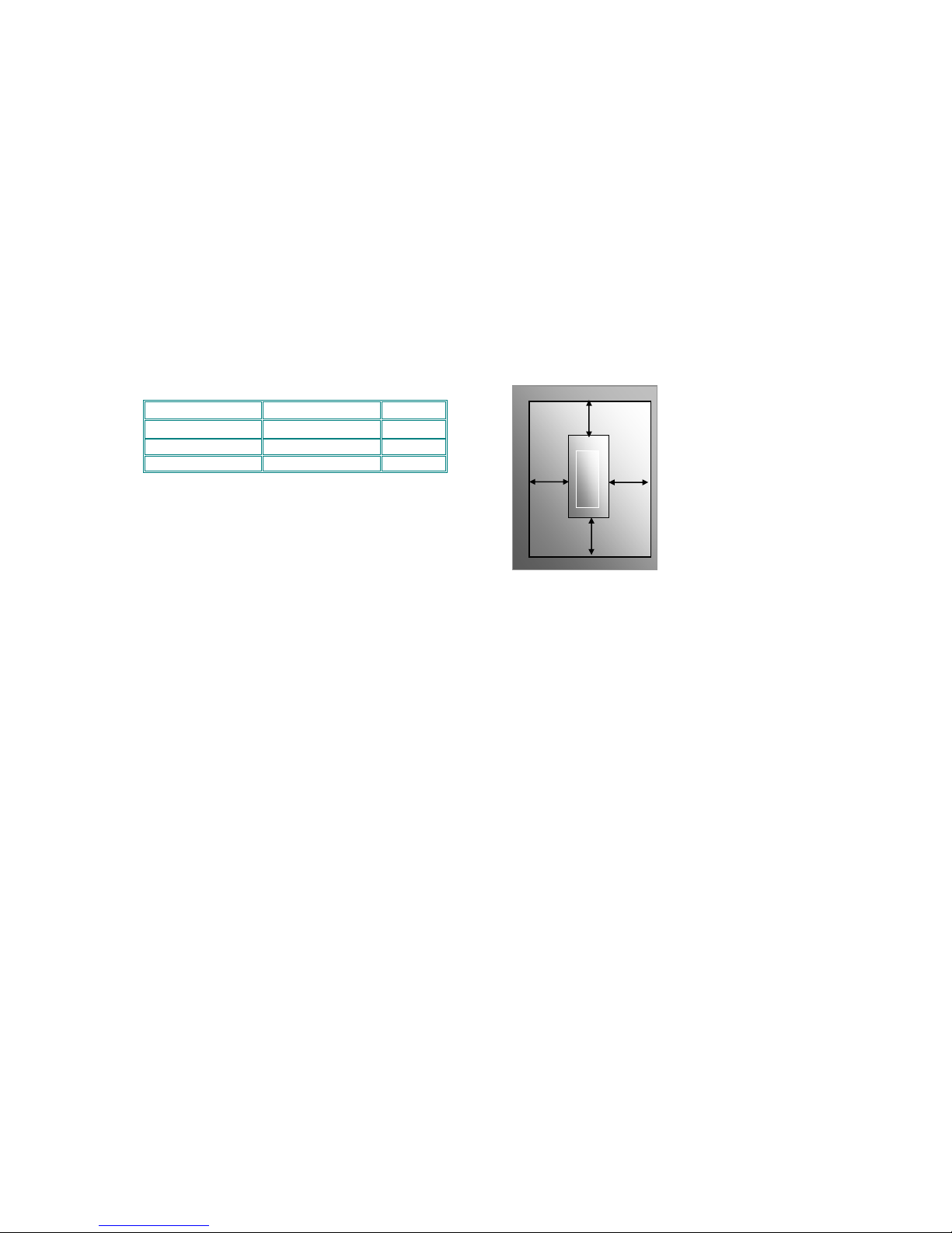
Avoid mounting of more inverters in vertical array. If absolutely necessary, keep double mounting distances
The table below, shows the minimum mounting distances in vertical and horizontal direction
Sufficient heat exchange of the cabinet must be guaranteed, to keep all operating conditions within the specified limits.
Framesize
Mounting
<30kw A≥150mm B≥50mm
≥30kw A≥200mm B≥75mm
A
B B
A
INVERTER
Distances for mounting in
cabinet
Fans:
All inverters out of the E800 series are forced ventilated. Specific parameters are used to set various fan
operating modes: Allways ON (F702=2), ON with inverter in running mode (F702=1), or temperature controlled (F702=0)
(F703=Temp. threshold)
see 14) Parameter group 700: Error handling and protection functions (F702-F703)
Maintenance and service:
Provided that the inverter is working in respect of specified environmental conditions, provided that the inverter is
used for proper application, and all instructions have been exactly followed for installation, putting in service and
operation, the inverter does not need any specific maintenance.
E800 – Rev.01 -EN- SOFT Rev. 2.04
© 2015 EURADRIVES EUROPE GmbH
- 15 -
4) Electrical wiring of E800 inverters
4) Electrical connection of E800 Inverters
E800 inverters have separate terminals for power- and control-connection. Adequate cables are requested for wiring the
inverter, all safety rules, reported in the first chapter of this manual are to observe.
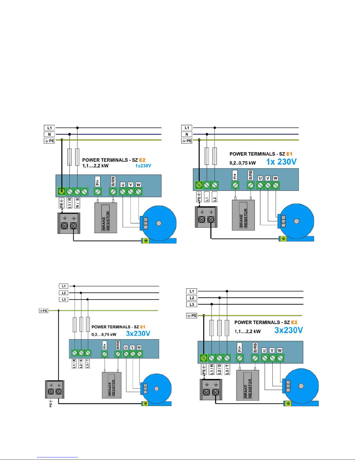
Power terminals:
There are different arrangements for power terminals, depending on inverter size and number of input phases.
230V Singlephase
0.2 – 0,75 kW – Framesize E1 1,5 - 2,2 kW - Framesize E2
230V Threephase
0.2 – 0,75 kW – Framesize E1
1,5 - 2,2 kW - Framesize E2
E800 / 3000 – Rev.04 -EN- SOFT Rev. 3.04
© 2014 EURADRIVES EUROPE GmbH
- 16 -
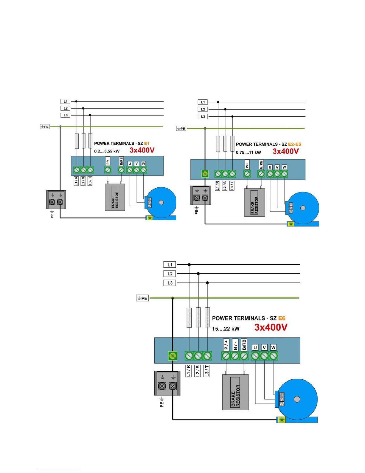
4) Electrical wiring of E800 inverters
400V Threephase
0.75 – 0,55 kW – Framesize E1 0,75 – 11 kW – Framesize E2-E5
15 – 22 kW – Framesize E6
E800 / 3000 – Rev.04 -EN- SOFT Rev. 3.04
© 2014 EURADRIVES EUROPE GmbH
- 17 -
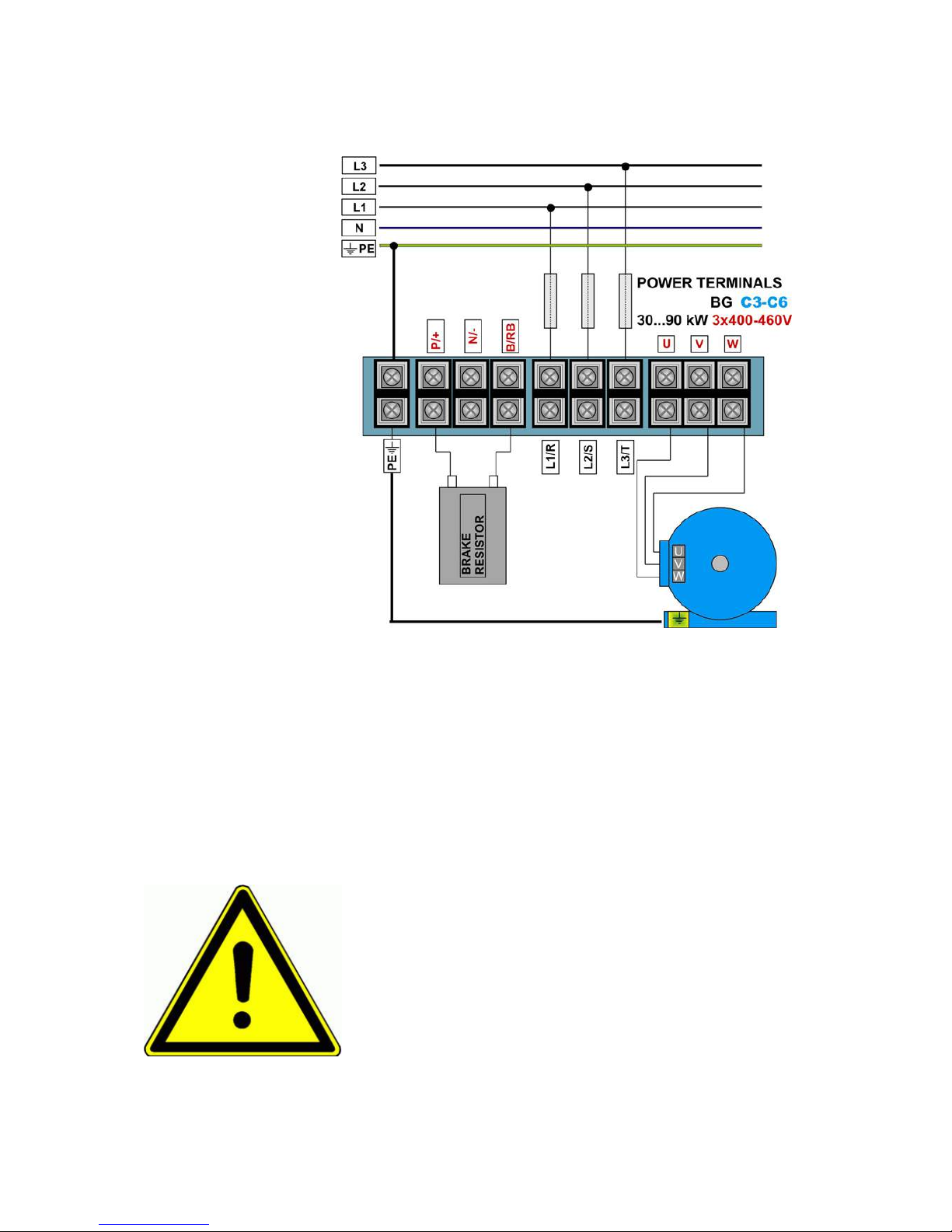
4) Electrical wiring of E800 inverters
400V Threephase above 30 kW C3.....C6
Brake resistor:
E800 inverters have build in chopper transistor as standard. An adequate brake resistor can be connected externaly. The
maximum cable lenght is 2mt, the crossection depends on the current through the resistor, calculated, considering the brake
switch on voltage of 800V and the resistor value.
The minimum resistor value for single inverter power ranges is reported in table on chapter: 2) Product overview / Product data
– the value in the table is the absolute minimum value – resistors with up to three times higher resistance value are
allowed.
Right dimensioning of the resistor, especially in sense of continuous power and peak power depends on the application (inertia,
speed, brake cycle rate).
EURADRIVES accessories program offers special resistors for all kind of application.
ATTENTION!! All stored dynamic energy of the system is converted in heat,
during the brake process - heat, dissipated in the brake resistor.
Overheating of the resistor, risk of burning and fire may be the consequence of
improper dimensioning, wrong parameter setting, inverter fault or power supply
over-voltage.
It is necessary to provide suitable electrical and mechanical protection of the
brake resistor
The rules in chapter 1) Common installation and safety rules are to observe.
EURADRIVES does not take any responsibility for any damage or risk, if
improper brake resistors are used.
E800 / 3000 – Rev.04 -EN- SOFT Rev. 3.04
© 2014 EURADRIVES EUROPE GmbH
- 18 -
 Loading...