

Page 1
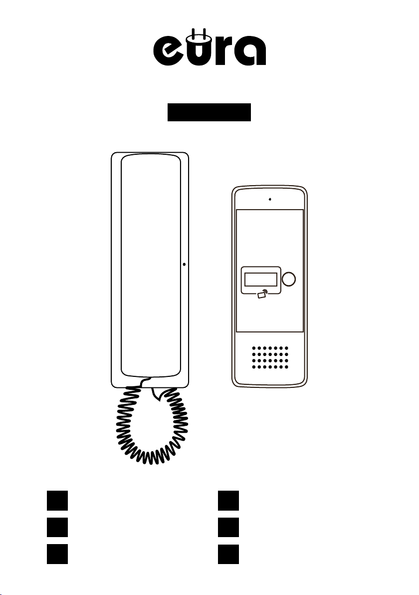
ADP-25A3
PL
ZESTAW DOMOFONOWY
EN
INTERCOM KIT
DE
GEGENSPRECHANLAGE
FR
KIT INTERPHONE
IT
KIT INTERFONO
ES
KIT DE INTERCOMUNICADOR
Page 2
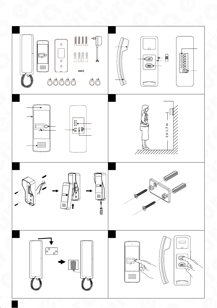
I. ZESTAWIENIE RYSUNKÓW / LIST OF FIGURES / ZUSAMMENFASSUNG DER ABBILDUNGEN/ LISTE DES FIGURES /
ELENCO DEI DISEGNI / I. LISTADO DE FIGURAS
1
2
4
6
23
1
7
5
98
3 4
1
2
4
5
3
JW1
A
G
D
V
J6 J1
6
7
S1
8
9
5 6
1
a
4
3
2
b
c
5
6
1
2 3 45
6
7
8
ab
7 8
2
Page 3
PL
PL
Skład zestawu:
1. Unifon - 1 szt.
2. Kaseta zewnętrzna
- 1 szt.
3. Daszek ochronny do
kasety zewnętrznej
- 1 szt.
4. Śruby samogwintujące
- 4 szt.
1
5. Zasilacz sieciowy
6. Kołki do montażu
- 4 szt.
7. Śruba zabezpieczająca
8. Brelok użytkownika
- 5 szt.
9. Brelok administratora
- 2 szt.
Budowa unifonu:
1. Głośnik
2. Mikrofon
3. Przycisk odblokowywa-
nia rygla
4. Przełącznik głośności
dzwonka: a. wysoki, b.
2
średni, c. niski
5. Wskaźnik LED
6. Przycisk otwierania
bramy
7. Zaciski połączeniowe
8. Gniazdo zasilania
12V DC
Budowa kasety:
1. Mikrofon
2. Daszek ochronny
3. Głośnik
4. Przycisk wywołania
5. Czytnik breloków
zbliżeniowych
6. Gniazdo rygla 12V DC
(elektrozaczepu)
3
7. Gniazdo do podłączenia
unifonu
8. Przycisk kodowania
nowych breloków
Administratora
9. Gniazdo przycisku
opuszczania posesji
Właściwie umiejscowienie
kasety zewnętrznej
4
Montaż daszku ochronnego
5a
Montaż kasety w daszku
ochronnym
5b
Instalacja ramki montażowej unifonu
6
Montaż unifonu na ścianie Installation of the handset
7
Prowadzenie rozmowy Conducting a conversation Gesprächsführung Conduite d’une conver-
8
EN DE FR IT ES
Set contents:
1. Intercom – 1 pc.
2. Outdoor station – 1 pc.
3. Protective cover for the
external casing – 1 pc.
4. Self-tapping screws
– 4 pcs.
5. Power socket – 1 pc.
6. Mounting pins – 4 pcs.
7. Security screw – 1 pc.
8. User key fob – 5 pcs.
9. Administrator key fob
– 2 pcs.
Handset structure:
1. Speaker
2. Microphone
3. Door lock release
button
4. Call volume switch:
high, medium, low
5. LED indicator
6. Gate opening button
7. Connection terminals
8. 12 V DC power socket
Construction of the
outdoor station:
1. Microphone
2. Protective cover
3. Speaker
4. Call button
5. Key fob reader
6. 12 V DC electric strike
output
7. Connection terminals
8. Button for program-
ming new key fobs
9. Administrator session
release button
Proper placement of the
outdoor station
Montage der Schutzabdeckung
Installation of the casing in
the protective cover
Installation of the protective frame in the recess
on the wall
Lieferumfang:
1. Innenstation – 1 Stk.
2. Außengehäuse – 1 Stk.
3. Schutzabdeckung für
das Außengehäuse
– 1 Stk.
4. Selbstschneidende
Schrauben – 4 Stk.
5. Strombuchse – 1 Stk.
6. Montagedübel – 4 Stk.
7. Sicherheitsschraube
– 1 Stk.
8. Benutzer-Schlüsselanhänger – 5 Stk.
9. Administrator- Schlüsselanhänger – 2 Stk.
Auau des Innenhörers:
1. Lautsprecher
2. Mikrofon
3. Türöner-Taste
4. Lautstärkeschalter:
hoch, mittel, niedrig
5. LED-Anzeige
6. Toröner-Taste
7. Anschlussklemmen
8. 12-V-DC-Strombuchse
Auau der Außenstation:
1. Mikrofon
2. Schutzabdeckung
3. Lautsprecher
4. Ruaste
5. Schlüsselanhänger-
Lesegerät
6. Ausgang für 12-V-DC
Türöner
7. Anschlussklemmen
8. Taste zur Program-
mierung neuer
Schlüsselanhänger
9. Taste zum Beenden der
Administrator-Sitzung
Richtige Platzierung des
Außengehäuses
Installation du couvercle
de protection
Montage des Gehäuses in
der Schutzabdeckung
Installation des Schutzrahmens in der Nische
Montage des Innenhörers
an der Wand
Contenu du kit :
1. Interphone – 1 pc.
2. Platine extérieure
– 1 pc.
3. Couvercle de protection
pour le boîtier externe
– 1 pc.
4. Vis autotaraudeuses
– 4 pcs.
5. Prise d’alimentation
– 1 pc.
6. Chevilles de montage
– 4 pcs.
7. Vis de sécurité – 1 pc.
8. Porte-clés utilisateur
– 5 pcs.
9. Porte-clés administrateur – 2 pcs.
Structure du combiné:
1. Haut-parleur
2. Microphone
3. Bouton d’ouverture de
la serrure
4. Commutateur de
volume: fort, moyen,
faible
5. Indicateur LED
6. Bouton d’ouverture de
portail
7. Bornes de connexion
8. Prise d’alimentation
12 V CC
Construction de la
Platine extérieure:
1. Microphone
2. Couvercle de protection
3. Haut-parleur
4. Bouton d’appel
5. Lecteur de porte-clés
6. Sortie pour gâche
électrique 12 V CC
7. Bornes de connexion
8. Bouton de program-
mation de nouveaux
porte-clés
9. Bouton de n de session administrateur
Placement correct du
platine extérieure
Installation du couvercle
de protection
Installation du boîtier
dans le
couvercle de protection
Installation du cadre de
protection dans la niche
Installation du combiné au
mur
sation
Contenuto del set:
1. Citofono – 1 pz.
2. Pulsantiera esterna
– 1 pz.
3. Copertura protettiva
per la custodia esterna
– 1 pz.
4. Viti autolettanti – 4 pz.
5. Presa di alimentazione
– 1 pz.
6. Tasselli di montaggio
– 4 pz.
7. Vite di sicurezza – 1 pz.
8. Portachiavi utente
- 5 pz.
9. Portachiavi amministratore – 2 pz.
Struttura del citofono:
1. Altoparlante
2. Microfono
3. Pulsante di sblocco
della serratura
4. Interruttore del volume:
alto, medio, basso
5. Indicatore LED
6. Pulsante di apertura
cancello
7. Terminali di collega-
mento
8. Presa di alimentazione
12V CC
Struttura della Pulsantiera esterna:
1. Microfono
2. Copertura protettiva
3. Altoparlante
4. Pulsante di chiamata
5. Lettore di portachiavi
6. Uscita per serratura
elettrica 12 V CC
7. Terminali di collegamento
8. Pulsante di programmazione di nuovi
portachiavi
9. Pulsante di rilascio sessione amministratore
Posizionamento corretto
della pulsantiera esterna
Installazione della copertura protettiva
Installazione della cassetta
nella copertura protettiva
Installazione del telaio
protettivo nella nicchia
Installazione del citofono a
parete
Conduzione della conver-
sazione
Contenido del conjunto:
1. Intercomunicador– 1 ud.
2. Panel exterior – 1 ud.
3. Cubierta protectora
para la caja externa
– 1 ud.
4. Tornillos autorroscantes
– 4 uds.
5. Toma de corriente
– 1 ud.
6. Tacos de montaje
– 4 uds.
7. Tornillo de seguridad
– 1 ud.
8. Llavero de usuario –
5 uds.
9. Llavero de administrador – 2 uds.
Estructura del interfono:
1. Altavoz
2. Micrófono
3. Botón de desbloqueo
de cerradura
4. Interruptor de volumen:
alto, medio, bajo
5. Indicador LED
6. Botón de apertura de
puerta
7. Terminales de conexión
8. Toma de alimentación
12 V CC
Estructura de la Panel
exterior:
1. Micrófono
2. Cubierta protectora
3. Altavoz
4. Botón de llamada
5. Lector de llaveros
6. Salida para cerradura
eléctrica de 12 V CC
7. Terminales de conexión
8. Botón para programar
nuevos llaveros
9. Botón de nalización de
sesión de administrador
Colocación correcta de la
panel exterior
Instalación de la cubierta
protectora
Instalación de la caja en la
cubierta protectora
Instalación del marco
protector en el hueco
Instalación del Intercomunicadores de Audio
Realización de una
conversación
3
Page 4
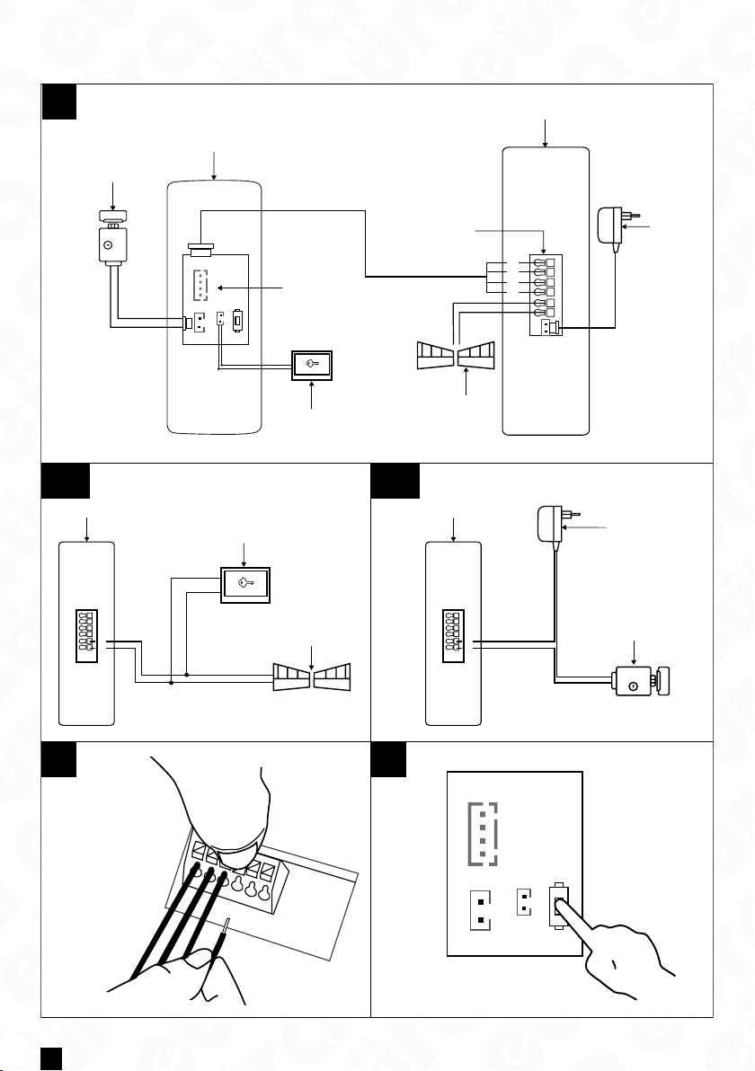
II. SCHEMATY INSTALACYJNE / INSTALLATION DIAGRAMS / INSTALLATIONSSCHEMAS / SCHÉMAS D’INSTALLA-
A
TION / SCHEMI DI INSTALLAZIONE / ESQUEMAS DE INSTALACIÓN
5
B1
2
1
*
7
JW1
1
A
2
G
3
D
4
V
S
J6 J1
3
1
N.O.
*
4
A
G
D
V
*
8
1 2 3 4 5 6
6
B2
1
2
1
*
1
2 3 4 5 6
N.O.
3
1
2 3 4 5 6
*
*
2
3
*
C D
1
2
3
4
5
6
4
JW1
A
G
D
V
J6 J1
S1
Page 5
PL
PL
Schemat połączeń
zestawu:
1. Rygiel/ Elektrozaczep
2. Kaseta zewnętrzna
3. Gniazdo 4 pinowe:
1. AUDIO (Niebieski)
2. GND (Czarny)
3. DATA (Zielony)
A
4. VCC (Brązowy)
4. Przycisk opuszczania
posesji
5. Unifon
6. Zasilacz
7. Magistrala zaciskowa
8. Automat bramy
Podłączenie automatu
bramy wjazdowej lub
garażowej:
1. Unifon
2. Przycisk otwierania
B1
bramy
3. Automat bramy/ Napęd
bramy
Podłączenie
odatkowego rygla
(otwieranie dodatkowej
furtki lub drzwi):
1. Unifon
B2
2. Zasilacz rygla/ elektrozaczepu
3. Rygiel/ Elektrozaczep
Podłączenie przewodów
C
do magistrali zaciskowej
Przycisk programowa-
D
nia S1
Dodatkowy element
*
wyposażenia
EN DE FR IT ES
Wiring diagram of the
set:
1. Lock/ Electric strike
2. Outdoor station
3. 4-pin socket:
1. AUDIO (Blue)
2. GND (Black)
3. DATA (Green)
4. VCC (Brown)
4. Gate exit button
5. Intercom
6. Power supply
7. Terminal block
8. Gate operator
Connection of the
driveway or garage gate
operator:
1. Intercom
2. Gate opening button
3. Gate operator/ Gate
drive
Connection of an
additional bolt (opening
an additional gate or
door):
1. Intercom
2. Power supply for the
bolt/ electric strike
3. Bolt/ Electric strike
Connection of wires to
the terminal block
Programming button S1 Programmiertaste S1
Additional equipment
Schaltplan des Sets:
1. Schloss / Elektro-
-Türöner
2. Außenstation
3. 4-polige Buchse:
1. AUDIO (Blau)
2. GND (Schwarz)
3. DATA (Grün)
4. VCC (Braun)
4. Torönungs-Taster
5. Innenstation
6. Netzteil
7. Klemmenblock
8. Torantrieb
Anschluss des
Einfahrtoder
Garagentorantriebs:
1. Gegensprechanlage
2. Torönungs-Taster
3. Torantrieb/
Torantriebseinheit
Anschluss eines
zusätzlichen Riegels
(Önen eines
zusätzlichen Tors oder
einer Tür):
1. Gegensprechanlage
2. Netzteil für den
Riegel/ Elektroschloss
3. Riegel/ Elektroschloss
Anschluss der Drähte an
die Klemmleiste
Element der Zusatzausstattung
Schéma de câblage
du kit :
1. Pêne/ Serrure électrique
2. Platine extérieure
3. Prise 4 broches :
1. AUDIO (Bleu)
2. GND (Noir)
3. DATA (Vert)
4. VCC (Marron)
4. Bouton de sortie du
terrain
5. Interphone
6. Alimentation électrique
7. Bloc de terminaison
8. Moteur de porte
Connexion de l’automatisme de porte d’entrée
ou de garage :
1. Interphone
2. Bouton d’ouverture
de la porte
3. Moteur de porte/
Moteur de portail
Connexion d’un verrou
supplémentaire
(ouverture d’une
porte ou d’un portail
supplémentaire) :
1. Interphone
2. Alimentation pour le
verrou/ serrure électrique
3. Verrou/ Serrure
électrique
Connexion des ls au
bloc de bornes
Bouton de
programmation S1
Équipement supplémentaire
Schema di collegamento
del kit:
1. Catenaccio/ Serratura
elettrica
2. Pulsantiera esterna
3. Presa a 4 pin:
1. AUDIO (Blu)
2. GND (Nero)
3. DATA (Verde)
4. VCC (Marrone)
4. Pulsante di uscita dalla
proprietà
5. Interfono
6. Alimentatore
7. Barra di morsetti
8. Motorino del cancello
Collegamento
dell’automazione del
cancello d’ingresso o del
garage:
1. Citofono
2. Pulsante di apertura
del cancello
3. Motorino del cancello/
Azionamento del
cancello
Collegamento di un
chiavistello aggiuntivo
(apertura di un cancello
o porta aggiuntiva):
1. Citofono
2. Alimentatore per il
chiavistello/ serratura
elettrica
3. Chiavistello/ Serratura
elettrica
Collegamento dei li
alla barra di morsetti
Pulsante di
programmazione S1
Accessorio aggiuntivo Equipamiento adicional
Diagrama de conexiones
del conjunto:
1. Cerradura / Cerradura
eléctrica
2. Panel exterior
3. Conector de 4 pines:
1. AUDIO (Azul)
2. GND (Negro)
3. DATA (Verde)
4. VCC (Marrón)
4. Botón de salida de la
propiedad
5. Intercomunicador
6. Fuente de alimentación
7. Bloque de terminales
8. Motor de puerta
Conexión del
automatismo de puerta
de entrada o garaje:
1.Intercomunicador
2. Botón de apertura de
la puerta
3. Motor de puerta/
Motor de portón
Conexión de un cerrojo
adicional (apertura de
una puerta o portón
adicional):
1. Intercomunicador
2. Fuente de
alimentación para el
cerrojo/ electroimán
3. Cerrojo/ Electroimán
Conexión de los cables
a la barra de terminales
Botón de programación S1
5
Page 6

PL
1. OGÓLNE ZASADY BEZPIECZNEGO UŻYTKOWANIA PRODUKTU
1. Instalacja urządzenia
- Wykwalikowany instalator: Instalację urządzenia powinien przeprowadzać wykwalikowany specjalista, aby unik-
nąć uszkodzenia sprzętu.
- Warunki środowiskowe: Domofon należy instalować w miejscu spełniającym wymagania pro ducenta dotyczące tem-
peratury, wilgotności oraz ochrony przed bezpośrednim działaniem deszczu, śniegu i promieniowania UV (chyba że
urządzenie jest przeznaczone do użytku zewnętrznego).
- Odległość od źródeł zakłóceń elektromagnetycznych: Unikać montażu urządzenia w pobliżu urządzeń emitujących
silne pola elektromagnetyczne (np. silniki elektryczne, kuchenki mikrofalowe).
- Ochrona przed przepięciami: Zaleca się zastosowanie zabezpieczenia przepięciowego w obwodzie zasilania urządze-
nia.
2. Bezpieczne użytkowanie
- Zasilanie: Domofon nal eży po dłąc zać wyłąc znie do źródła zasilania o para metr ach zgodnych ze specy kacją technic z-
ną podaną przez producenta. Nie należy używać uszkodzonych kabli ani zasilaczy.
- Przewody: Przewody sygnałowe i zasilające powinny być zabezpieczone przed uszkodzeniami mechanicznymi i nie
powinny być przeciążone.
- Kontakt z wodą: Jeśli urządzenie nie jest przeznaczone do pracy w warunkach zewnętrznych, należy unikać jego kon-
taktu z wodą lub nadmierną wilgocią.
- Dzieci: Urządzenie powinno być używane w sposób uniemożliwiający dzieciom jego demontaż, zmianę ustawień lub
dostęp do elementów pod napięciem.
3. Konserwacja i serw is
- Czyszc zenie: Do czyszczenia urządzenia używać suchej lub lekko wil gotnej ście reczki. Nie stosować środków ch emicz-
nych ani wody pod ciśnieniem.
- Serwis: W przy padku uszkodzenia lub awarii urządzenia należ y skont aktować się z autoryzowanym serwisem. Samo -
dzielne próby naprawy mogą unieważnić gwarancję oraz stwarzać zagrożenie.
- Aktualizacje oprogramowania: Jeśli Domofon wymaga aktualizacji oprogramowania, należy je pobierać wyłącznie z
ocjalnej strony producenta lub z poziomu autoryzowanej aplikacji.
4. Ochrona środowiska
- Recykling: Urządzenie po zakończeniu eksploatacji należy przekazać do punktu zbiórki elektrośmieci, zgodnie z dy-
rektywą WEEE (Dyrektywa o zużytym sprzęcie elektrycznym i elektronicznym).
- Materiały: Domofon jest zgodny z dyrekty wą RoHS, co oznacza ograniczenie użycia niebezpiecznych substancji w
procesie produkcji.
5. Wskazówki prawne
- Certykacja CE: Urządzenie spełnia podstawowe wymagania bezpieczeństwa i kompatybilności elektromagnetycz-
nej zgodnie z oznaczeniem CE oraz jest zgodne z odpowiednimi dyrektywami.
6. Ostrzeżenia
- Nie używaj urządzenia w warunkach niezgodnych z zaleceniami producenta, ponieważ może to prowadzić do uszko-
dzenia urządzenia lub zagrożenia dla zdrowia.
- W przypadku zauważenia dymu, iskrzenia lub innych oznak uszkodzenia natychmiast odłącz urządzenie od zasilania
i skontaktuj się z serwisem.
Pamiętaj: Przestrzeganie powyższych zasad jest niezbędne dla zapewnienia bezpieczeństwa użytkowania oraz zgod-
ności z obowiązującymi przepisami. Szczegółowe informacje można znaleźć w instrukcji obsługi dostarczonej przez producenta.
6
Page 7
PL
2. INSTA LAC JA ZE STAWU
2.1. INSTALACJA UNIFONU
UWAGA !
Standardowa wysokość instalacji unifonu po zawieszeniu wynosi ok. 145 cm, niemniej jego
położenie można dostosować do indywidualnych potrzeb użytkowników.
1. W wybranym miejscu na ścianie, poprzez 2 otwory w ramce montażowej odznaczyć na ścianie miejsca na kołki montażowe (rys. 6).
2. W zaznaczonych miejscach nawiercić 2 otwory montażowe Ø 6mm, a następnie umieścić w nich kołki montażowe.
3. Za pomocą 2 wkrętów do ściany przykręcamy ramkę montażową modułu (rys. 6) w sposób zapewniający łatwe i
estetyczne doprowadzenie przewodu łączącego zestaw i przewodu zasilającego.
4. Do zacisków magistrali zaciskowej (rys. C) znajdującej się na odwrocie modułu podłączamy poszczególne żyły przewodu według schematu (rys. A)
5. Do gniazda słuchawkowego podłączamy słuchawkę.
6. Do gniazda zasilacza podłączamy zasilacz.
7. Na tylnej części obudowy modułu znajdują się 2 otwory służące do powieszenia go na ramce montażowej. Należy
delikatnie powiesić moduł, tak aby 2 uchwyty z ramki znalazły się w otworach obudowy (rys.7).
8. Na koniec podłączamy zasilacz do sieci ~230 V/50Hz.
9. Sprawdź, czy wszystkie połączenia są bezpieczne i czy urządzenie działa poprawnie po podłączeniu do prądu.
Jak podłączyć przewody do magistrali zaciskowego
1. Naciśnij przycisk i włóż przewód do odpowiedniego otworu (rys. C).
2. Zwolnij przycisk, aby zacisnąć przewód na miejscu.
3. Delikatnie pociągnij przewód, aby upewnić się, że jest dobrze zaciśnięty.
Informacje dodatkowe
• Przewód łączący jednostkę wewnętrzną i zewnętrzną:
• Dystans 0 - 30m: 4×0,5 mm²
• Dystans 30 - 50m: 4×1,0 mm²
Gniazdo J6 w jednostce zewnętrznej jest używane do podłączenia rygla. Przy podłączaniu rygla używaj przewodu 2×1,0
mm², a długość przewodu nie powinna przekraczać 10m. Zaciski 5/6 w unifonie są używane do podłączenia np. napędu
bramy.
2.2. INSTALACJA KASETY ZEWNĘTRZNEJ
Moduł zewnętrzny jest fabrycznie przystosowany do montażu natynkowego.
UWAGA!
Właściwie umiejscowienie modułu zewnętrznego decyduje o komforcie pracy z urządzeniem. Zaleca się przed wykonaniem
otworu montażowego doświadczalne dobranie miejsca montażu. Standardowa wysokość instalacji kasety zewnętrznej
wynosi od 140 do 170 cm.
Sposób montażu:
1. Odkręcić dolną śrubę mocującą i oddzielić kasetę od daszka ochronnego.
2. W wybranym miejscu na ścianie/ słupku, poprzez 2 otwory w dnie daszka ochronnego odznaczyć na ścianie miejsca
na kołki montażowe (rys. 5a).
3. W zaznaczonych miejscach nawiercić 2 otwory montażowe Ø 6mm, a następnie umieścić w nich kołki montażowe.
4. Za pomocą 2 wkrętów montażowych przymocować daszek ochronny kasety zewnętrznej do ściany.
5. Do modułu kasety podłączyć 4 żyły przewodu biegnącego do modułu wewnętrznego (unifonu) zgodnie ze schematem pokazanym na (rys. A).
6. Podłączyć do modułu kasety 2 żyły przewodu prowadzące do rygla elektromagnetycznego (element wyposażenia
dodatkowego) zgodnie ze schematem A
7. Umieścić kasetę zewnętrzną w zamocowanym uprzednio do ściany daszku ochronnym wykorzystując otwór do zaczepienia daszku oraz przykręcić dolną śrubę mocującą (rys. 5b)
* Do montażu kasety zaleca się użycie śrub załączonych do zestawu. Użycie śrub dłuższych niż dołączone do zestawu powoduje trwałe
uszkodzenie płyty głównej.
UWAGA!
1. Nie należy dokonywać żadnych podłączeń ani przełączeń przewodów jeżeli urządzenie jest podłączone do sieci ~230V.
Nie przestrzeganie powyższego zalecenia może doprowadzić do uszkodzenia urządzenia. Przed dokonywaniem montażu, czy demontażu urządzenia należy uprzednio odłączyć zasilacz od sieci.
2. Uszkodzenia spowodowane zalaniem modułu nie są objęte gwarancją.
7
Page 8
PL
3. PROWADZENIE ROZMOWY
W momencie, gdy osoba przy wejściu wciśnie przycisk na kasecie zewnętrznej, w module wewnętrznym (unifonie) uruchamia się sygnał gongu. Po podniesieniu słuchawki modułu wewnętrznego można prowadzić rozmowę z osobą przy
wejściu. Osoba znajdującasię wewnątrz pomieszczenia ma możliwość zdalnego otwarcia furtki naciskając przycisk zwalniania rygla elektromagnetycznego na unifonie oraz otwarcia bramy (drugiej furtki, drzwi, itp.) naciskając
przycisk otwierania bramy
UWAGA!
Podczas czuwania domofonu, jeśli słuchawka unifonu zostanie podniesiona, możliwe będzie prowadzenie rozmowy oraz
zwolnienie rygla i otwarcie bramy.
4. PROGR AMOWANIE
4.1. DODAWANIE BRE LOKÓW UŻYTKOWNIKÓW
UWAGA!
Breloki dołączone do zestawu są fabrycznie zaprogramowane.
Urządzenie umożliwia dodanie breloków użytkownika, których zbliżenie przed czytnikiem umożliwia zwolnienie
rygla. Zestaw zawiera dwa breloki administratora: brelok dodawania (Add Card) i brelok usuwania (Delete Card) oraz 5
breloków użyt kowników. Aby dodać brelok użytkownika należy w trybie standardowej pracy urzą dzenia przeciągnąć
brelok dodawania (Add Card) przed czytnikiem do momentu po jawienia się sygnału akustycznego. Następnie należy
przeciągnąć przed czytnikiem nowy brelok użytkownika, po czym ponownie przeciągnąć brelok dodawania (Add Card)
- pojawienie się sygnału akustycznego zatwierdzi pomyślne dodanie breloka.
4.2. USUWANIE BRELOKÓW UŻYTKOWNIKÓW
W celu usunięcia użytkownika należy w trybie standardowej pracy urządzenia przeciągnąć brelok usuwania (Delete
Card) przed czytnikiem aż do momentu poja wienia się sygnału akustycznego. Następnie należy przeciągnąć przed
czytnikiem brelok użytkownika, który chcemy usunąć z pamięci po czym ponownie przecią gnąć brelok usuwania
(Delete Card) - pojawienie się sygnału akustycznego zatwierdzi pomyślne usunięcie breloka.
4.3 INICJOWANIE NOWYCH BRELOKÓW ADMINISTRATORA
Naciśnij i przytrzymaj przycisk S1 przez 3 sekundy, zwolnij przycisk po usłyszeniu 3 krótkich tonów i 1 długiego tonu.
Następnie przesuń 2 breloki, z których pierwszy zostanie utworzony jako brelok dodawania (Add Card), a drugi jako
brelok usuwania (Delete Card) Po wykonaniu programowania jednostka zewnętrzna automatycznie wróci do normalnego trybu pracy. Dodawanie nowych breloków administratora zostało zakończone.
5. OTWIERANIE BRAMY WJAZDOWEJ LUB DODATKOWEGO WEJŚCIA
Oprócz zdalnego otwierania furtki lub drzwi wejściowych, domofon oferuje również możliwość sterowania drugim wejściem, np. napędem bramy wjazdowej, napędem bramy garażowej, ryglem przy drugiej furtce lub drzwiach, itp.
Do sterowania drugim wejściem służą zaciski 5 i 6 z tyłu obudowy unifonu. Zaciski 5 i 6 stanowią wyjście przekaźnika
typu N.O. (normalnie otwarte), zatem do poprawnej współpracy napęd bramy powinien mieć również umożliwiać wyzwalanie krótkim zwarciem zacisków wejściowych (N.O.). Wówczas zaciski 5 i 6 na wyjściu unifonu wystarczy połączyć
np. równolegle z przyciskiem zwiernym wewnątrz posesji, służącym do ręcznego uruchomienia napędu bramy (schemat
B1). Istnieje możliwość podłączenia do zacisków 5 i 6 standardowego rygla elektromagnetycznego, otwierającego np.
drugą furtkę na posesję. Wówczas do zasilania rygla należy zastosować szeregowo oddzielny zasilacz o parametrach
(napięciu zasilania i wydajności prądowej) dostosowanych do parametrów tego rygla (schemat B2).
6. SYGNAŁY DŹWIĘKOWE
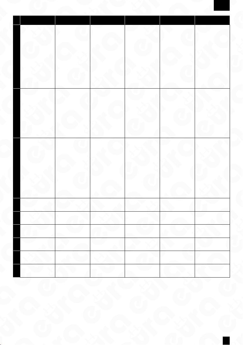
Karta prawidłowa 1 krótki sygnał
Karta nieprawidłowa 2 krótkie sygnały
Wejście/wyjście z trybu dodawania kart jeden długi sygnał
Wejście/wyjście z trybu usuwania kart jeden długi sygnał
Prawidłowe dodanie karty użytkownika 1 krótki sygnał
Nieprawidłowe dodanie karty użytkownika 2 krótkie sygnały
Zduplikowany numer karty 2 krótkie sygnały
Wejście do trybu dodawania kart administratora 3 krótkie sygnały i 1 długi
CZYSZCZENIE I KONSERWACJA POSZCZEGÓLNYCH ELEMENTÓW ZESTAWU
W wypadku zabrudzenia poszczególnych części zestawu, należy je czyścić wyłącznie miękką, lekko wilgotną szmatką z
dodatkiem niewielkiej ilości środków czyszczących przeznaczonych do mycia elementów z tworzyw sztucznych.
UWAGA!
Używanie środków myjących opartych na bazie rozpuszczalników, benzyn itp. oraz środków zawierających substancje ścierne
jest niedopuszczalne!
8
Page 9
7. SPECYFIKACJA TECHNICZNA ZESTAWU
ZESTAW
Napięcie zasilania 12 V DC
Pobór mocy - czuwanie / praca <1,5W / <6,5W
Ilość przewodów łączących 4
Ilość obsługiwanych wyjść 2
KASETA ZEWNĘTRZNA
Ilość obsługiwanych lokali 1
Ilość obsługiwanych wyjść 1
Rodzaje wyjść Wyjście 1: 12V DC 350mA
Czas aktywacji rygla Wyjście 1: 5 sekund
Materiał obudowy Stop aluminium
Sposób montażu kasety zewn. Natynkowy
Daszek ochronny Tak
Czytnik breloków zbliżeniowych Tak
Maks. moc promieniowania <5mW
PL
Częstotliwość pracy 125kHz (UNIQUE)
Współczynnik ochrony IP65
Dopuszczalna wilgotność względna 10%...90% RH
Temperaturowy zakres pracy kasety -20ºC ~ +50ºC
Wymiary kasety zewn. (W x SZ x G) 170 x 65 x 39 mm
Waga netto kasety 330 g
UNIFON
Ilość melodii gongu 1
Ilość obsługiwanych wyjść 1
Rodzaje wyjść Wyjście 2: N.O. max 1A/ 24V DC
Czas aktywacji wyjścia Wyjście 2: 1 sekunda
Stopień ochrony IP20
Dopuszczalna wilgotność względna 10%...90% RH
O
Temperaturowy zakres pracy unifonu -10
Wymiary unifonu (W x SZ x G) 210 x 67 x 56 mm
Waga netto unifonu 260 g
*producent zastrzega sobie dokonywanie zmian parametrów technicznych bez uprzedzenia
C ~ +55OC
9
Page 10

EN
1. GENERAL SAFETY GUIDELINES FOR USING THE PRODUCT
1. Device Installation
- Qualied Installer: The device should be installed by a qualied specialist to avoid damage to the equipment.
- Environmental Conditions: The intercom should be installed in a location that meets the manufacturer’s requirements
for temperature, humidity, and protection from direc t exposure to rain, snow, and UV radiation (unless the device is
designed for outdoor use).
- Distance from Electromagnetic Interference Sources: Avoid installing the device near equipment emitting strong
electromagnetic elds (e.g., electric motors, microwave ovens).
- Surge Protection: It is recommended to use surge protection in the device’s power circuit.
2.Safe Usage
- Power Supply: The intercom should only be connected to a power source with parameters consistent with the techni-
cal specications provided by the manufacturer. Do not use damaged cables or power adapters.
- Cables: Signal and power cables should be protected from mechanical damage and should not be overloaded.
- Contact with Water: If the device is not designed for outdoor use, avoid contact with water or excessive moisture.
- Children: The device should be used in a way that prevents children from disassembling it, changing settings, or ac-
cessing live components.
3. Maintenance and Ser vice
- Cleaning: Use a dry or slightly damp cloth to clean the device. Do not use chemical agents or pressurized water.
- Service: In case of damage or malfunction, contact an authorized service center. Attempting to repair the device
yourself may void the warranty and create a hazard.
- Soware Updates: If the intercom requires a soware update, download it only from the manufacturer’s ocial we-
bsite or through an authorized application.
4.Environmental Protection
- Recycling: Aer the device’s end of life, it should be disposed of at an electronic waste collection point in accordance
with the WEEE Directive (Waste Electrical and Electronic Equipment Directive).
- Materials: The intercom complies with the RoHS Directive, which restricts the use of hazardous substances in the
manufacturing process.
5.Legal Information
- CE Certication: The device meets the basic safety and electromagnetic compatibility requirements according to the
CE marking and is compliant with relevant directives.
6.Warnings
- Do not use the device under conditions that do not comply with the manufacturer’s recommendations, as this may
lead to device damage or health hazards.
- If you notice smoke, sparking, or other signs of damage, immediately disconnect the device from the power supply
and contact the service center.
Remember: Following the above guidelines is essential to ensure safe usage and compliance with applicable regulations.
Detailed information can be found in the user manual provided by the manufacturer.
10
Page 11
EN
2. INSTALL ATION OF THE K IT
2.1. INSTALL ATION OF THE PHONE
ATTENTION!
The standard installation height of the phone aer mounting is approximately 145 cm, however, its position can be adjusted
to meet the individual needs of the users.
1. In the selected location on the wall, mark the positions for the mounting plugs by using the two holes in the mounting
frame (Fig. 6).
2. Drill two mounting holes Ø 6mm at the marked positions and insert the mounting plugs.
3. Using two screws, attach the module’s mounting frame to the wall (Fig. 6) in a way that ensures easy and aesthetically
pleasing cable routing for the connection and power supply wires.
4. Connect the individual wires of the cable to the terminal bus clamps (Fig. C) on the back of the module according to
the wiring diagram (Fig. A).
5. Connect the handset to the handset socket.
6. Connect the power supply to the power socket.
7. On the back of the module housing, there are two holes for hanging it on the mounting frame. Carefully hang the
module so that the two brackets on the frame align with the housing holes (Fig. 7).
8. Finally, plug the power supply into the ~230 V/50Hz mains.
9. Check that all connections are secure and that the device operates correctly aer being powered on.
How to connect wires to the terminal block:
1. Press the button and insert the wire into the appropriate hole (Fig. C).
2. Release the button to clamp the wire in place.
3. Gently pull the wire to ensure it is securely clamped.
Additional information:
Cable connecting the internal and external units:
• Distance 0 - 30m: 4×0.5 mm²
• Distance 30 - 50m: 4×1.0 mm²
The J6 socket on the external unit is used for connecting the lock. When connecting the lock, use a 2×1.0 mm² cable, and
the cable length should not exceed 10m. Terminals 5/6 in the intercom are used to connect, for example, the gate drive.
2.2. INSTALLATION OF THE OUTDOOR STATION
The outdoor module is factory pre-congured for surface mounting.
ATTENTIION!
The correct location of the external module determines the comfort of working with the device. It is recommended to
experimentally select the mounting location before making the mounting hole. The standard installation height of the
external cassette is from 140 to 170 cm.
Mounting procedure:
1. Unscrew the bottom mounting screw and separate the external panel from the protective cover.
2. In the chosen location on the wall/post, mark the spots for the mounting plugs on the wall through the 2 holes in the
bottom of the protective cover (see Fig. 5a).
3. Drill 2 mounting holes Ø 6mm in the marked locations, and then insert the mounting plugs.
4. Using 2 mounting screws, attach the protective cover of the external panel to the wall.
5. Connect the 4 wires running to the internal module (intercom) to the cassette module according to the diagram
shown in (Fig. A).
6. Connect the 2 wires leading to the electromagnetic lock (additional equipment) to the cassette module according to
diagram A.
7. Place the external panel into the previously mounted protective cover on the wall using the hole for securing the
cover, and screw in the bottom mounting screw (see Fig. 5b).
* For mounting the outdoor station, it is recommended to use the screws provided in the kit. Using screws longer than those provided in the
kit may cause permanent damage to the mainboard.
ATTENTIION!
1. Do not make any connections or switch wires while the device is connected to the ~230V power supply. Failure to follow
this recommendation may result in device damage. Before installation or disassembly, disconnect the power supply
from the mains.
2. Damage caused by water ingress into the module is not covered by the warranty.
11
Page 12
EN
3. CONDUCTING A CONVERSATION
When the person at the entrance presses the button on the external panel, the gong signal is activated in the internal
module (intercom). Aer picking up the handset of the internal module, a conversation can be conducted with the person
at the entrance. The person inside the room has the ability to remotely open the gate by pressing the electromagnetic
lock release button on the intercom and to open the gate ((second gate, door, etc.) by pressing the gate
opening button.
ATTENTIION!
During intercom standby mode, if the handset is lied, it will be possible to conduct a conversation, release the lock, and open
the gate.
4. PROGRAMMING
4.1. ADDING USER REMOTE CONTROL KEYS
ATTENTIION!
The remote control keys included in the set are pre-programmed from the factory.
The device allows the addition of user key fobs, which, when brought close to the reader, will release the lock. The set
includes two administrator key fobs: the add key fob (Add Card) and the delete key fob (Delete Card), as well as 5 user key
fobs. To add a user key fob, in the standard operating mode of the device, swipe the add key fob (Add Card) in front of the
reader until an acoustic signal appears. Then, swipe the new user key fob in front of the reader, and nally, swipe the add
key fob (Add Card) again — an acoustic signal will conrm the successful addition of the key fob.
4.2. REMOVING USER KEY FOBS
To remove a user key fob, in the standard operating mode of the device, swipe the delete key fob (Delete Card) in front
of the reader until an acoustic signal appears. Then, swipe the user key fob you want to remove from memory in front of
the reader, and nally, swipe the delete key fob (Delete Card) again — the appearance of an acoustic signal will conrm
the successful removal of the key fob.
4.3. INITIALIZING NEW ADMINISTRATOR KEY FOBS
Press and hold the S1 button for 3 seconds, then release the button aer hearing 3 short tones and 1 long tone. Next,
swipe 2 key fobs, the rst one will be set as the add key fob (Add Card) and the second one as the delete key fob (Delete
Card). Aer programming, the external unit will automatically return to normal operation mode. The process of adding
new administrator key fobs is complete.
5. OPENING THE GATE OR ADDITIONAL ENTRY
In addition to remotely opening the entrance gate or door, the intercom also oers the ability to control a second entry,
such as a driveway gate opener, garage door opener, lock at a second gate, or door, etc. To control the second entry,
use the 5 and 6 terminals at the back of the intercom housing. Terminals 5 and 6 serve as a N.O. (normally open) relay
output, so for proper operation, the gate opener should also allow triggering by briey shorting the input terminals
(N.O.). In this case, simply connect terminals 5 and 6 at the intercom output, for example, in parallel with a push button
inside the premises used to manually operate the gate opener (see diagram B1). It is also possible to connect a standard
electromagnetic lock to terminals 5 and 6, for example, to open a second gate to the premises. In this case, the lock
must be powered by a separate power supply with parameters (voltage and current rating) appropriate for the lock’s
specications (see diagram B2).
6. SOUND SIGNALS
Valid card 1 short signal
Invalid card 2 short signals
Entering/exiting the card adding mode 1 long signal
Entering/exiting the card deletion mode 1 long signal
Successful user card addition 1 short signal
Unsuccessful user card addition 1 short signal
Duplicated card number 2 short signals
ntering administrator card adding mode 3 short signals and 1 long
CCLEANING AND MAINTENANCE OF INDIVIDUAL COMPONENTS OF THE SET
In case of dirt on individual parts of the set, clean them only with a so, slightly damp cloth with a small amount of
cleaning agents designed for cleaning plastic parts.
ATTENTIION!
The use of cleaning agents based on solvents, gasoline, etc., and products containing abrasive substances is prohibited!
12
Page 13
7. TECHNICAL SPECIFICATION OF THE KIT
SET
Power supply voltage 12 V DC
Power consumption - standby / operation <1,5W / <6,5W
Number of connecting wires 4
Number of supported outputs 2
OUTDOOR STATION
Number of supported premises 1
Number of supported outputs 1
Types of outputs Output 1: 12V DC 350mA
Lock activation time Output 1: 5 seconds
Housing material Aluminum alloy
Mounting method Surface mounting
Protective cover Yes
Proximity keyfob reader Yes
Maximum radiation power <5mW
EN
Operating frequency 125kHz (UNIQUE)
Protection rating IP65
Permissible relative humidity 10%...90% RH
Operating temperature range of the outdoor station -20ºC ~ +50ºC
External cassette dimensions (H x W x D) 170 x 65 x 39 mm
Net weight of the outdoor station 330 g
INTERCOM
Number of gong melodies 1
Number of outputs supported 1
Types of outputs Output 2: N.O. max 1A/ 24V DC
Activation time of output Output 2: 1 second
Protection rating IP20
Permissible relative humidity 10%...90% RH
O
Operating temperature range of the intercom -10
Intercom dimensions (H x W x D) 210 x 67 x 56 mm
Net weight of the intercom 260 g
*the manufacturer reserves the right to make changes to technical parameters without prior noticea
C ~ +55OC
13
Page 14

DE
1. ALLGEMEINE SICHERHEITSHINWEISE FÜR DIE BENUTZUNG DES PRODUKTS
1. Geräteinstallation
- Qualizierter Installateur: Die Installation des Geräts sollte von einem qualizierten Fachmann durchgeführt werden,
um Beschädigungen der Ausrüstung zu vermeiden.
- Umweltbedingungen: Die Gegensprechanlage sollte an einem Ort installiert werden, der die Anforderungen des Her-
stellers hinsichtlich Temperatur, Lufeuchtigkeit und Schutz vor direkter Einwirkung von Regen, Schnee und UV-
-Strahlung erfüllt (es sei denn, das Gerät ist für den Außenbereich vorgesehen).
- Abstand zu elektromagnetischen Störquellen: Vermeiden Sie die Installation des Gerät s in der Nähe von Geräten, die
starke elektromagnetische Felder abgeben (z. B. Elektromotoren, Mikrowellenherde).
- Überspannungsschutz: Es wird empfohlen, einen Überspannungsschutz im Stromkreis des Geräts zu verwenden.
2. Sicherer Betrie b
- Stromversorgung: Die Gegensprechanlage sollte nur an eine Stromquelle mit den vom Hersteller angegebenen tech-
nischen Spezikationen angeschlossen werden. Beschädigte Kabel oder Netzteile sollten nicht verwendet werden.
- Kabel: Signal- und Stromkabel sollten vor mechanischen Beschädigungen geschützt werden und nicht überlastet
werden.
- Kontak t mit Wasser: Wenn das Gerät nicht für den Außenbereich vorgesehen ist, vermeiden Sie den Kontakt mit
Wasser oder übermäßiger Feuchtigkeit.
- Kinder: Das Gerät sollte so verwendet werden, dass Kinder es nicht demontieren, Einstellungen ändern oder Zugang
zu unter Spannung stehenden Teilen haben können.
3. Wartu ng und Service
- Reinigung: Verwenden Sie ein trockenes oder leicht feuchtes Tuch, um das Gerät zu reinigen. Verwenden Sie keine
chemischen Mittel oder Wasser unter Druck.
- Service: Im Falle einer Beschädigung oder eines Defekts wenden Sie sich an einen autorisierten Ser vice. Eigenständige
Reparaturversuche können die Garantie ungültig machen und ein Risiko darstellen.
- Soware-Updates: Wenn die Gegensprechanlage ein Soware-Update er fordert, laden Sie es nur von der oziellen
Website des Herstellers oder über eine autorisierte Anwendung herunter.
4. Umwelt schutz
- Recycling: Nach dem Ende der Lebensdauer des Geräts sollte es gemäß der WEEE-Richtlinie (Richtlinie über Elektro-
und Elektronikaltgeräte) an einer Sammelstelle für Elektroschrott entsorgt werden.
- Materialien: Die Gegensprechanlage entspricht der RoHS-Richtlinie, die die Verwendung gefährlicher Stoe im Her-
stellungsprozess einschränkt.
5. Recht liche Hinweise
- CE-Zertizierung: Das Gerät erfüllt die grundlegenden Sicherheits- und elektromagnetischen Verträglichkeitsanfor-
derungen gemäß der CE-Kennzeichnung und ist mit den relevanten Richtlinien konform.
6. Warnungen
- Verwenden Sie das Gerät nicht unter Bedingungen, die den Empfehlungen des Herstellers nicht entsprechen, da dies
zu Geräteschäden oder Gesundheitsrisiken führen kann.
- Wenn Sie Rauch, Funken oder andere Anzeichen von Beschädigung bemerken, trennen Sie das Gerät sofort vom
Stromnetz und wenden Sie sich an den Service.
Denken Sie daran: Die Einhaltung der oben genannten Richtlinien ist entscheidend, um die Sicherheit und die Ein-
haltung der geltenden Vorschrien zu gewährleisten. Weitere Informationen nden Sie in der Bedienungsanleitung des
Herstellers.
14
Page 15
DE
2. INSTALLATION DES SETUPS
2.1. INSTALLATION DES GEGENSPRECHANLAGE
ACHTUNG!
Die Standardmontagehöhe des Interfons nach der Befestigung beträgt ca. 145 cm, kann jedoch an die individuellen
Bedürfnisse der Benutzer angepasst werden.
1. Markieren Sie an der ausgewählten Stelle an der Wand die Positionen für die Befestigungsdübel durch die zwei Löcher
im Montagerahmen (Abb. 6).
2. Bohren Sie zwei Montagelöcher mit Ø 6 mm an den markierten Stellen und setzen Sie die Dübel ein.
3. Befestigen Sie den Montagerahmen des Moduls mit zwei Schrauben an der Wand (Abb. 6), sodass eine einfache und
ordentliche Kabelführung für die Verbindung und die Stromversorgung gewährleistet ist.
4. Verbinden Sie die einzelnen Adern des Kabels mit den Klemmen der Anschlussleiste (Abb. C) auf der Rückseite des
Moduls gemäß dem Schaltplan (Abb. A).
5. Schließen Sie den Hörer an die Hörermue an.
6. Schließen Sie das Netzteil an die Netzbuchse an.
7. Auf der Rückseite des Modulgehäuses benden sich zwei Löcher zur Auängung am Montagerahmen. Hängen Sie
das Modul vorsichtig auf, sodass die zwei Halterungen des Rahmens in die Gehäuselöcher passen (Abb. 7).
8. Zum Schluss schließen Sie das Netzteil an das ~230 V/50Hz-Stromnetz an.
9. Überprüfen Sie, ob alle Verbindungen sicher sind und ob das Gerät nach dem Anschluss ordnungsgemäß funktioniert.
Wie man die Drähte an die Anschlussklemme anschließt
1. Drücken Sie die Taste und stecken Sie den Draht in das entsprechende Loch (Abb. C).
2. Lassen Sie die Taste los, um den Draht an Ort und Stelle zu klemmen.
3. Ziehen Sie den Draht vorsichtig, um sicherzustellen, dass er festgeklemmt ist.
Zusätzliche Informationen
• Kabelverbindung zwischen der Innen- und Außeneinheit:
• Entfernung 0 - 30m: 4×0,5 mm²
• Entfernung 30 - 50m: 4×1,0 mm²
Die J6-Buchse im externen Modul wird zum Anschluss des Riegels verwendet. Beim Anschluss des Riegels verwenden
Sie ein Kabel 2×1,0 mm², und die Kabellänge sollte 10 m nicht überschreiten. Die Klemmen 5/6 im Intercom werden z.B.
zum Anschluss des Torantriebs verwende.
2.2. INSTALLATION DER AUSSENSTATION
Das Außengerät ist werkseitig für die Aufputzmontage vorbereitet.
ACHTUNG!
Der richtige Standort des Außenmoduls bestimmt den Komfort bei der Nutzung des Geräts. Es wird empfohlen, den
Montageort vor dem Bohren des Montageschachtes experimentell auszuwählen. Die Standardinstallationhöhe der
Außenkassette liegt zwischen 140 und 170 cm.
Montagemethode:
1. Lösen Sie die untere Befestigungsschraube und trennen Sie das externe Panel vom Schutzdach.
2. Markieren Sie an der Wand/Säule den Ort für die Montageschrauben durch 2 Löcher im Schutzdachboden (siehe Abb.
5a).
3. Bohren Sie an den markierten Stellen 2 Montagedurchmesser Ø 6mm und setzen Sie die Montageschrauben ein.
4. Befestigen Sie das Schutzdach des externen Panels mit 2 Montageschrauben an der Wand.
5. Schließen Sie 4 Drahtleitungen, die zum Innenmodul (Intercom) führen, an das Kassettengerät gemäß dem Diagramm
(Abb. A) an.
6. Schließen Sie 2 Drahtleitungen, die zum Elektromagnetischen Riegel (zusätzliches Zubehör) führen, an das Kassettengerät gemäß dem Diagramm A an.
7. Setzen Sie das externe Panel in das zuvor an der Wand montierte Schutzdach ein, indem Sie das Loch zum Befestigen
des Dachs nutzen, und schrauben Sie die untere Befestigungsschraube ein (siehe Abb. 5b).
* Für die Montage der Outdoor-Station wird empfohlen, die im Set enthaltenen Schrauben zu verwenden. Die Verwendung von längeren
Schrauben als die mitgelieferten kann zu dauerhaen Schäden an der Hauptplatine führen..
ACHTUNG!
1. Keine Anschlüsse oder Kabelumschaltungen vornehmen, wenn das Gerät an das ~230V-Netz angeschlossen ist. Die
Nichteinhaltung dieser Anweisung kann zu Schäden am Gerät führen. Vor der Installation oder Demontage des Geräts
muss das Netzteil vom Stromnetz getrennt werden.
2. Schäden durch das Eindringen von Wasser in das Modul sind nicht von der Garantie abgedeckt.
15
Page 16
DE
3. FÜHREN EINES GESPRÄCHS
Wenn die Person am Eingang die Taste an der Außenstation drückt, wird das Gongsignal im Innenmodul (Türsprechanlage) aktiviert. Nach Abheben des Hörers des Innenmoduls kann ein Gespräch mit der Person am Eingang geführt werden.
Die Person im Raum hat die Möglichkeit, das Tor aus der Ferne zu önen, indem sie die Taste zur Entriegelung des elektromagnetischen Schlosses an der Türsprechanlage drückt und das Tor (zweites Tor, Tür usw.) durch Drücken
der Torönungstaste zu önen.
ACHTUNG!
Im Standby-Modus der Türsprechanlage kann bei Abheben des Hörers ein Gespräch geführt, das Schloss entriegelt und das
Tor geönet werden.
4. PROGRAMMIERUNG
4.1. HINZUFÜGEN VON BENUTZER-FERNBEDIENUNGSKEYS
ACHTUNG!
Die Fernbedienungsschlüssel, die im Set enthalten sind, sind werkseitig vorprogrammiert.
Das Gerät ermöglicht das Hinzufügen von Benutzer-Fernbedienungsschlüsseln, deren Annäherung an den Leser das
Entriegeln des Schlosses ermöglicht. Das Set enthält zwei Administrator-Schlüssel: den Hinzufügen-Schlüssel (Add Card)
und den Löschen-Schlüssel (Delete Card) sowie 5 Benutzerschlüssel. Um einen Benutzerschlüssel hinzuzufügen, ziehen
Sie im Standardbetrieb des Geräts den Hinzufügen-Schlüssel (Add Card) vor dem Leser, bis ein akustisches Signal erscheint. Ziehen Sie dann den neuen Benutzerschlüssel vor dem Leser und ziehen Sie schließlich erneut den Hinzufügen-
-Schlüssel (Add Card)—ein akustisches Signal bestätigt das erfolgreiche Hinzufügen des Schlüssels.
4.2. ENTFERNEN VON BENUTZER-FERNBEDIENUNGSSCHLÜSSELN
Um einen Benutzerschlüssel zu entfernen, ziehen Sie im Standardbetrieb des Geräts den Löschen-Schlüssel (Delete Card)
vor dem Leser, bis ein akustisches Signal erscheint. Ziehen Sie dann den Benutzerschlüssel, den Sie aus dem Speicher
entfernen möchten, vor dem Leser und ziehen Sie schließlich erneut den Löschen-Schlüssel (Delete Card)—das Aureten
eines akustischen Signals bestätigt das erfolgreiche Entfernen des Schlüssels.
4.3. INITIALISIEREN NEUER ADMINISTRATOR-SCHLÜSSEL
Drücken und halten Sie die S1-Taste für 3 Sekunden, und lassen Sie die Taste los, nachdem Sie 3 kurze Töne und 1 langen
Ton gehört haben. Ziehen Sie dann 2 Schlüssel, wobei der erste als Hinzufügen-Schlüssel (Add Card) und der zweite als
Löschen-Schlüssel (Delete Card) festgelegt wird. Nach der Programmierung kehrt die Außeneinheit automatisch in den
normalen Betriebsmodus zurück. Der Prozess des Hinzufügens neuer Administrator-Schlüssel ist abgeschlossen.
5. ÖFFNEN DES TORS ODER DES ZUSÄTZLICHEN EINGANGS
Neben dem Fernönen des Eingangstors oder der Tür bietet die Gegensprechanlage auch die Möglichkeit, einen zweiten
Eingang zu steuern, wie zum Beispiel einen Torantrieb, einen Garagentorantrieb, ein Schloss an einem zweiten Tor oder
einer Tür usw. Zur Steuerung des zweiten Eingangs verwenden Sie die Klemmen 5 und 6 an der Rückseite des Gehäuses
des Gegensprechgeräts. Die Klemmen 5 und 6 dienen als N.O. (normalerweise oene) Relaisausgänge, sodass der Torantrieb auch durch kurzes Kurzschließen der Eingangsklemmen (N.O.) ausgelöst werden sollte. In diesem Fall verbinden Sie
einfach die Klemmen 5 und 6 am Ausgang des Gegensprechgeräts, zum Beispiel parallel mit einem Taster innerhalb des
Grundstücks, der zur manuellen Bedienung des Torantriebs verwendet wird (siehe Schaltbild B1). Es ist auch möglich, ein
Standard-Elektromagnetisches Schloss an die Klemmen 5 und 6 anzuschließen, um zum Beispiel ein zweites Tor zum
Grundstück zu önen. In diesem Fall muss das Schloss mit einer separaten Stromversorgung betrieben werden, deren
Parameter (Spannung und Stromstärke) den Spezikationen dieses Schlosses entsprechen (siehe Schaltbild B2)
6. TONSIGNALE
Gültige Karte 1 kurzer Signalton
Ungültige Karte 2 kurze Signalzeichen
Eingabe/Ausgabe des Kartenhinzufügemodus 1 langer Signalton
Eingabe/Ausgabe des Kartenlöschmodus 1 langer Signalton
Erfolgreiche Benutzerkarte hinzugefügt 1 kurzer Signalton
Fehlerhae Benutzerkarte hinzugefügt 2 kurze Signalzeichen
Duplizierte Kartennummer 2 kurze Signalzeichen
Eingabe des Administrator-Kartenhinzufügemodus 3 kurze Signalzeichen und 1 langer Signalton
REINIGUNG UND WARTUNG DER EINZELNEN KOMONENTEN DES SETS
Im Falle von Verschmutzungen einzelner Teile des Sets, diese nur mit einem weichen, leicht feuchten Tuch und einer
kleinen Menge Reinigungsmittel reinigen, die für die Reinigung von Kunststoeilen vorgesehen sind.
ACHTUNG!
Die Verwendung von Reinigungsmitteln auf Basis von Lösungsmitteln, Benzin usw. sowie von Produkten, die abrasive Substanzen enthalten, ist nicht zulässig!
16
Page 17
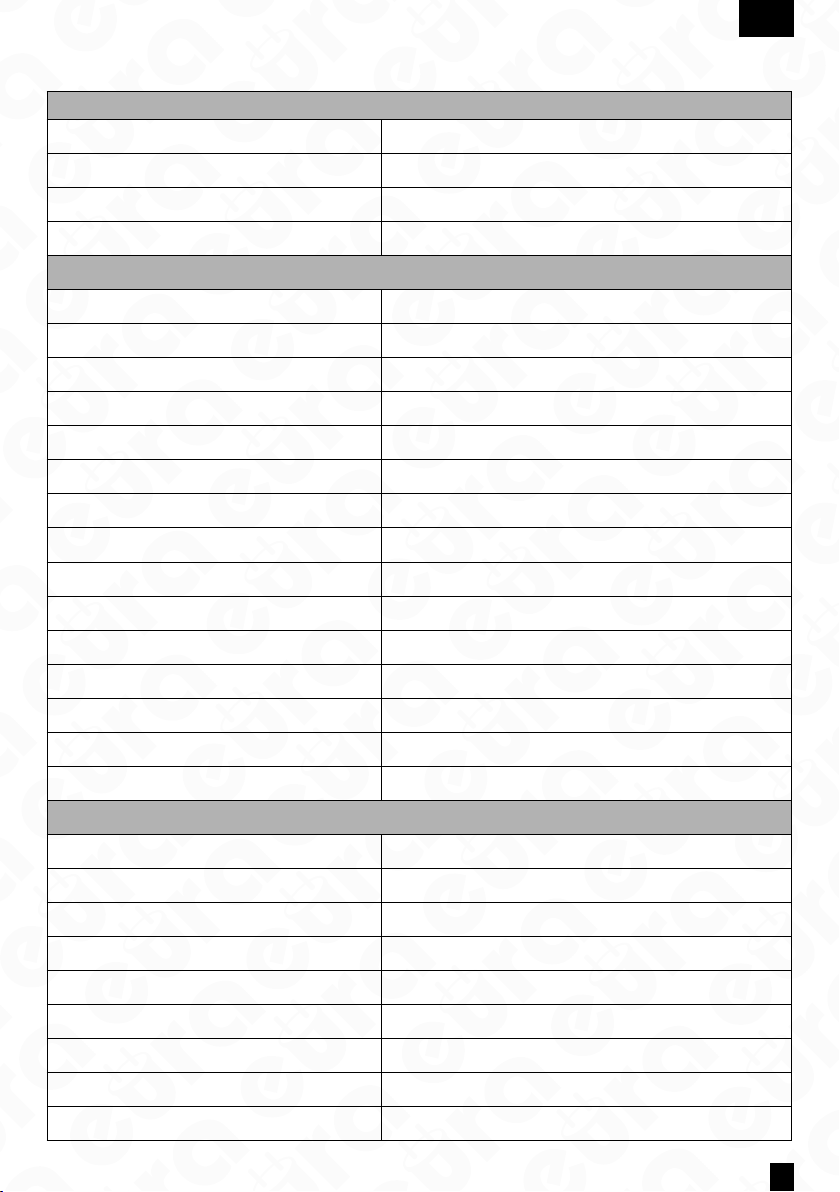
7. TECHNISCHE SPEZIFIKATION DES SETS
SET
Versorgungsspannung Napięcie zasilania 12 V DC
Leistungsaufnahme - Standby / Betrieb <1,5W / <6,5W
Anzahl der Verbindungsdrähte 4
Anzahl der unterstützten Ausgänge 2
AUSSENSTATION
Anzahl unterstützter Wohneinheiten 1
Anzahl unterstützter Ausgänge 1
Art der Ausgänge Ausgang 1: 12V DC 350mA
Türöner-Aktivierungsdauer Ausgang 1: 5 Sekunden
Gehäusematerial Aluminiumlegierung
Montageart Außenstation Aufputzmontage
Wetterschutzdach Ja
Lesegerät für Nahbereichskarten Ja
Max. Sendeleistung <5mW
DE
Betriebsfrequenz 125kHz (UNIQUE)
Schutzart (IP-Code) IP65
Zulässige relative Lufeuchtigkeit 10%...90% RH
Betriebstemperaturbereich Außenstation -20ºC ~ +50ºC
Abmessungen Außenstation (B x H x T) 170 x 65 x 39 mm
Nettogewicht Außenstation 330 g
INNENSTATION
Anzahl Klingelmelodien 1
Anzahl unterstützter Ausgänge 1
Art des Ausgangs Ausgang 2: N.O. max 1A/ 24V DC
Ausgangsaktivierungsdauer Ausgang 2: 1 Sekunde
Schutzart (IP-Code) IP20
Zulässige relative Lufeuchtigkeit 10%...90% RH
O
Betriebstemperaturbereich Unifon -10
Abmessungen Unifon (B x H x T) 210 x 67 x 56 mm
Nettogewicht innerstation 260 g
*der hersteller behält sich das recht vor, technische parameter ohne vorherige ankündigung zu ändern
C ~ +55OC
17
Page 18

FR
1. CONSIGNES DE SÉCURITÉ GÉNÉRALES POUR L’UTILISATION DU PRODUIT
1. Installation de l’appareil
- Installateur qualié : L’appareil doit être installé par un spécialiste qualié pour éviter d’endommager l’équipement.
- Conditions environnementales : L’interphone doit être installé dans un endroit répondant aux exigences du fabricant
en matière de température, d’humidité et de protection contre l’exposition directe à la pluie, à la neige et aux rayons
UV (sauf si l’appareil est conçu pour une utilisation extérieure).
- Distance des sources d’interférences électromagnétiques : Évitez d’installer l’appareil près d’équipements émettant
des champs électromagnétiques puissants (par exemple, moteurs électriques, fours à micro-ondes).
- Protection contre les surtensions : Il est recommandé d’utiliser une protection contre les surtensions dans le circuit
d’alimentation de l’appareil.
2. Utilisation sécurisée
- Alimentation : L’interphone doit être connecté uniquement à une source d’alimentation dont les paramètres corre-
spondent aux spécications techniques fournies par le fabricant. N’utilisez pas de câbles ou d’adaptateurs endommagés.
- Câbles : Les câbles de signal et d’alimentation doivent être protégés contre les dommages mécaniques et ne doivent
pas être surchargés.
- Contact avec l’eau : Si l’appareil n’est pas conçu pour une utilisation extérieure, évitez tout contact avec l’eau ou une
humidité excessive.
- Enfants : L’appareil doit être utilisé de manière à empêcher les enfants de le démonter, de modier les réglages ou
d’accéder aux composants sous tension.
3. Maintenance et ser vice
- Nettoyage : Utilisez un chion sec ou légèrement humide pour net toyer l’appareil. N’utilisez pas de produits chimi-
ques ou d’eau sous pression.
- Service : En cas de dommage ou de dysfonctionnement, contactez un centre de service agréé. Tenter de réparer
l’appareil vous-même peut annuler la garantie et créer un danger.
- Mises à jour logicielles : Si l’interphone nécessite une mise à jour logicielle, téléchargez-la uniquement à partir du site
ociel du fabricant ou via une application autorisée.
4. Protection de l’environnement
- Recyclage : Après la n de vie de l’appareil, il doit être éliminé dans un point de collecte de déchets électroniques con-
formément à la directive DEEE (Directive sur les Déchets d’Équipements Électriques et Électroniques).
- Matériaux : L’interphone est conforme à la directive RoHS, qui limite l’utilisation de substances dangereuses dans le
processus de fabrication.
5. Informations légales
- Certication CE : L’appareil répond aux exigences de base en matière de sécurité et de compatibilité électromagnéti-
que conformément au marquage CE et est conforme aux direc tives pertinentes.
6. Avertissements
- N’utilisez pas l’appareil dans des conditions non conformes aux recommandations du fabricant, car cela pourrait en-
traîner des dommages à l’appareil ou des risques pour la santé.
- Si vous remarquez de la fumée, des étincelles ou d’autres signes de dommage, débranchez immédiatement l’appareil
de l’alimentation électrique et contactez le service.
N’oubliez pas: Le respect des directives ci-dessus est essentiel pour garantir une utilisation sûre et la conformité aux
réglementations en vigueur. Des infor mations détaillées sont disponible s dans le manuel d’utilisation fourni par le fabric ant.
18
Page 19
FR
2. INSTALL ATION DU KIT
2.1. INSTALLATION DE L’INTERPHONE
ATTENTION !
La hauteur standard d’installation de l’interphone après montage est d’environ 145 cm, mais sa position peut être ajustée en
fonction des besoins individuels des utilisateurs.
1. À l’emplacement choisi sur le mur, marquez les positions des chevilles de xation en utilisant les deux trous du cadre
de montage (Fig. 6).
2. Percez deux trous de montage de Ø 6 mm aux endroits marqués, puis insérez les chevilles.
3. Fixez le cadre de montage du module au mur avec deux vis (Fig. 6) en veillant à assurer un passage facile et esthétique
des câbles de connexion et d’alimentation.
4. Branchez les diérents ls du câble aux bornes du bus de connexion (Fig. C) situées à l’arrière du module en suivant
le schéma de câblage (Fig. A).
5. Connectez le combiné à la prise du combiné.
6. Branchez l’alimentation sur la prise prévue à cet eet.
7. À l’arrière du boîtier du module, deux trous permettent de l’accrocher au cadre de montage. Suspendez délicatement
le module de manière à ce que les deux supports du cadre s’insèrent dans les trous du boîtier (Fig. 7).
8. Enn, branchez l’alimentation sur le réseau ~230 V/50Hz.
9. Vériez que toutes les connexions sont sécurisées et que l’appareil fonctionne correctement après la mise sous tension.
Comment connecter les ls au bornier
1. Appuyez sur le bouton et insérez le l dans le trou approprié (Fig. C).
2. Relâchez le bouton pour maintenir le l en place.
3. Tirez délicatement le l pour vous assurer qu’il est bien serré.
Informations supplémentaires
Câble reliant l’unité intérieure et extérieure:
• Distance 0 - 30m: 4×0,5 mm²
• Distance 30 - 50m: 4×1,0 mm²
La prise J6 sur l’unité extérieure est utilisée pour connecter le verrou. Lors de la connexion du verrou, utilisez un câble
2×1,0 mm², et la longueur du câble ne doit pas dépasser 10 m. Les bornes 5/6 dans l’interphone sont utilisées pour connecter, par exemple, le moteur de la porte.
2.2.INSTALLATION DE LA STATION EXTÉRIEURE
Le module extérieur est préconguré en usine pour une installation en surface.
ATTENTION!
L’emplacement correct du module extérieur détermine le confort d’utilisation de l’appareil. Il est recommandé de choisir
expérimentalement l’emplacement de montage avant de percer le trou de montage. La hauteur d’installation standard de la
cassette extérieure est comprise entre 140 et 170 cm.
Méthode d’installation :
1. Dévisser la vis de xation inférieure et séparer le panneau extérieur du toit de protection.
2. À l’endroit choisi sur le mur/poteau, marquez les emplacements des chevilles de xation sur le mur à travers les 2 trous
dans le fond du toit de protection (voir Fig. 5a).
3. Percez 2 trous de montage Ø 6mm aux emplacements marqués, puis insérez les chevilles de montage.
4. Fixez le toit de protection du panneau extérieur au mur à l’aide de 2 vis de montage.
5. Connectez les 4 ls allant vers le module interne (interphone) au module de la cassette selon le schéma indiqué à (Fig.
A).
6. Connectez les 2 ls allant vers le verrouillage électromagnétique (équipement supplémentaire) au module de la cassette selon le schéma A.
7. Placez le panneau extérieur dans le toit de protection monté préalablement sur le mur en utilisant le trou pour xer le
toit, puis revissez la vis de xation inférieure (voir Fig. 5b).
* Il est recommandé d’utiliser les vis fournies dans l’ensemble pour l’installation de la station extérieure. L’utilisation de vis plus longues que celles
fournies dans l’ensemble peut endommager dénitivement la carte principale.
ATTENTION!
1. Ne procédez à aucun branchement ni changement de câblage lorsque l’appareil est connecté au réseau ~230V. Le non-
-respect de cette recommandation peut entraîner des dommages à l’appareil. Avant toute installation ou démontage,
débranchez l’alimentation du réseau.
2. Les dommages causés par l’inltration d’eau dans le module ne sont pas couverts par la garantie.
19
Page 20
FR
3. CONDUITE D’UNE CONVERSATION
Lorsque la personne à l’entrée appuie sur le bouton du panneau extérieur, le signal de gong est activé dans le module
intérieur (interphone). En décrochant le combiné du module intérieur, il est possible de converser avec la personne à l’entrée. La personne à l’intérieur de la pièce peut ouvrir à distance le portillon en appuyant sur le bouton de déverrouillage
de la serrure électromagnétique sur l’interphone et ouvrir le portail (second portillon, porte, etc.) en appuyant
sur le bouton d’ouverture du portail.
ATTENTION!
En mode veille de l’interphone, si le combiné est décroché, il sera possible de converser, de déverrouiller la serrure et d’ouvrir
le portail.
4. PROGRAMMATION
4.1. AJOUTER DES CLÉS DE TÉLÉCOMMANDE UTILISATEUR
ATTENTION!
Les clés de télécommande incluses dans l’ensemble sont préprogrammées en usine.
L’appareil permet l’ajout de clés de télécommande utilisateur, dont le rapprochement devant le lecteur permet de déverrouiller le loquet. L’ensemble comprend deux clés d’administrateur : la clé d’ajout (Add Card) et la clé de suppression (Delete Card), ainsi que 5 clés utilisateur. Pour ajouter une clé utilisateur, en mode de fonctionnement standard de l’appareil,
faites glisser la clé d’ajout (Add Card) devant le lecteur jusqu’à ce qu’un signal acoustique apparaisse. Ensuite, faites glisser
la nouvelle clé utilisateur devant le lecteur, puis faites de nouveau glisser la clé d’ajout (Add Card) — un signal acoustique
conrmera l’ajout réussi de la clé.
4.2. SUPPRESSION DES CLÉS DE TÉLÉCOMMANDE UTILISATEUR
Pour supprimer une clé utilisateur, en mode de fonctionnement standard de l’appareil, faites glisser la clé de suppression
(Delete Card) devant le lecteur jusqu’à ce qu’un signal acoustique apparaisse. Ensuite, faites glisser devant le lecteur la
clé utilisateur que vous souhaitez supprimer de la mémoire, puis faites de nouveau glisser la clé de suppression (Delete
Card) — un signal acoustique conrmera la suppression réussie de la clé.
4.3. INITIALISATION DES NOUVELLES CLÉS D’ADMINISTRATEUR
Appuyez et maintenez enfoncé le bouton S1 pendant 3 secondes, puis relâchez le bouton après avoir entendu 3 brefs bips
et 1 long bip. Ensuite, faites glisser 2 clés, la première sera dénie comme la clé d’ajout (Add Card) et la seconde comme
la clé de suppression (Delete Card). Après la programmation, l’unité externe reviendra automatiquement au mode de
fonctionnement normal. L’ajout des nouvelles clés d’administrateur est terminé.
5. OUVERTURE DU PORTAIL OU DE L’ENTRÉE ADDITIONNELLE
En plus d’ouvrir à distance le portail ou la porte d’entrée, l’interphone ore également la possibilité de contrôler une deuxième
entrée, telle qu’un moteur de porte de garage, un moteur de porte d’entrée, une serrure pour un deuxième portail ou porte, etc.
Pour contrôler la deuxième entrée, utilisez les bornes 5 et 6 à l’arrière du boîtier de l’interphone. Les bornes 5 et 6 servent
de sortie relais N.O. (normalement ouverte), de sorte que le moteur de porte doit également permettre un déclenchement par un court-circuit des bornes d’entrée (N.O.). Dans ce cas, connectez simplement les bornes 5 et 6 à la sortie de
l’interphone, par exemple en parallèle avec un bouton à l’intérieur de la propriété servant à actionner manuellement le
moteur de la porte (voir schéma B1). Il est également possible de connecter une serrure électromagnétique standard aux
bornes 5 et 6, par exemple pour ouvrir un second portail vers la propriété. Dans ce cas, la serrure doit être alimentée par
une alimentation séparée dont les paramètres (tension et intensité) sont adaptés aux spécications de cette serrure (voir
schéma B2).
6. SIGNALS SONORES
Carte valide 1 signal court
Carte invalide 2 signaux courts
Entrée/sortie du mode ajout de cartes 1 long signal
Entrée/sortie du mode suppression de cartes 1 long signal
Ajout réussi de la carte utilisateur 1 signal court
Ajout de carte utilisateur échoué 2 signaux courts
Numéro de carte dupliqué 2 signaux courts
Entrée en mode ajout de carte administrateur 3 signaux courts et 1 long
NETTOYAGE ET ENTRETIEN DES COMPOSANTS INDIVIDUELS DU KIT
En cas de salissure de certaines parties du kit, nettoyez-les uniquement avec un chion doux légèrement humide, en
ajoutant une petite quantité de nettoyant destiné à nettoyer les éléments en plastique.
ATTENTION!
L’utilisation de produits de nettoyage à base de solvants, de benzine, etc., ainsi que de produits contenant des substances
abrasives est interdite!
20
Page 21
7. SPÉCIFICATION TECHNIQUE DU KIT
SET
Tension d'alimentation 12 V DC
Consommation électrique - veille / fonctionnement <1,5W / <6,5W
Nombre de ls de connexion 4
Nombre de sorties prises en charge 2
PLATINE EXTÉRIEURE
Nombre de logements pris en charge 1
Nombre de sorties prises en charge 1
Types de sorties Sortie 1: 12V CC 350mA
Durée d'activation de la gâche Sortie 1 : 5 secondes
Matériau du boîtier Alliage d’aluminium
Type de montage platine de rue Montage en saillie
Visière de protection Oui
Lecteur de badges de proximité Oui
Puissance rayonnée max. <5mW
FR
Fréquence de fonctionnement 125kHz (UNIQUE)
Indice de protection IP65
Humidité relative admissible 10%...90% RH
Plage de température de fonctionnement platine -20ºC ~ +50ºC
Dimensions platine de rue (L x H x P) 170 x 65 x 39 mm
Poids net platine de rue 330 g
INTERPHONE
Nombre de mélodies de la cloche 1
Nombre de sorties prises en charge 1
Types de sorties Sortie 2: N.O. max 1A/ 24V DC
Temps d'activation de la sortie Sortie 2: 1 seconde
Classe de protection IP20
Humidité relative admissible 10%...90% RH
O
Plage de température de fonctionnement de l'interphone -10
Dimensions de l'interphone (L x H x P) 210 x 67 x 56 mm
Poids net de l'interphone 260 g
* le fabricant se réserve le droit de modier les paramètres techniques sans préavis
C ~ +55OC
21
Page 22

IT
1. NORME GENERALI DI SICUREZZA PER L’USO DEL PRODOTTO
1. Installazione del dispositivo
- Installatore qualicato: Il dispositivo deve essere installato da uno specialista qualicato per evitare danni all’appa-
recchiatura.
- Condizioni ambientali: Il citofono deve essere installato in un luogo che soddis i requisiti del produttore per tem-
peratura, umidità e protezione dall’esposizione diret ta a pioggia, neve e raggi UV (a meno che il dispositivo non sia
proget tato per uso esterno).
- Distanza dalle fonti di interferenza elet tromagnetica: Evitare di installare il dispositivo vicino a apparecchiature che
emettono forti campi elettromagnetici (ad esempio, motori elettrici, forni a microonde).
- Protezione dalle sovratensioni: Si consiglia di utilizzare una protezione dalle sovratensioni nel circuito di alimentazione
del dispositivo.
2. Uso sicuro
- Alimentazione: Il citofono deve essere collegato solo a una fonte di alimentazione con parametri conformi alle speci-
che tecniche fornite dal produttore. Non utilizzare cavi o alimentatori danneggiati.
- Cavi: I cavi di segnale e di alimentazione devono essere protet ti da danni meccanici e non devono essere sovraccaricati.
- Contatto con l’acqua: Se il dispositivo non è progettato per uso esterno, evitare il contatto con acqua o umidità ec-
cessiva.
- Bambini: Il dispositivo deve essere utilizzato in modo da impedire ai bambini di smontarlo, modicare le impostazioni
o accedere a componenti sot to tensione.
3. Manutenzione e ser vizio
- Pulizia: Utilizzare un panno asciutto o leggermente umido per pulire il dispositivo. Non utilizzare agenti chimici o
acqua sot to pressione.
- Servizio: In caso di danni o malfunzionamenti, contattare un centro assistenza autorizzato. Tentativi di riparazione
autonomi possono invalidare la garanzia e creare rischi.
- Aggiornamenti soware: Se il citofono richiede un aggiornamento so ware, scaricarlo solo dal sito uciale del pro-
duttore o tramite un’applicazione autorizzata.
4. Protezione ambientale
- Riciclaggio: Dopo la ne del ciclo di vita del dispositivo, deve essere smaltito presso un punto di raccolta di riuti elet-
tronici in conformità alla direttiva RAEE (Direttiva sui Riuti di Apparecchiature Elettriche ed Elettroniche).
- Materiali: Il citofono è conforme alla diret tiva RoHS, che limita l’uso di sostanze pericolose nel processo di produzione.
5. Informazioni legali
- Certicazione CE: Il dispositivo soddisfa i requisiti di base di sicurezza e compatibilità elettromagnetica secondo la
marcatura CE ed è conforme alle direttive pertinenti.
6. Avver tenze
- Non utilizzare il dispositivo in condizioni non conformi alle raccomandazioni del produttore, poiché ciò potrebbe cau-
sare danni al dispositivo o rischi per la salute.
- Se si nota fumo, scintille o altri segni di danneggiamento, scollegare immediatamente il dispositivo dall’alimentazione
e contat tare il servizio.
Ricorda: Il rispet to delle linee guida sopra indicate è essenziale per garantire un uso sicuro e la conformità alle normative
vigenti. Informazioni dettagliate sono disponibili nel manuale d’uso fornito dal produttore.
22
Page 23
IT
2. INSTALLAZIONE DEL KIT
2.1. INSTALLAZIONE DELL’INTERFONO
ATTENZIONE!
L’altezza standard di installazione dell’interfono dopo il montaggio è di circa 145 cm, ma la sua posizione può essere adattata
alle esigenze individuali degli utenti.
1. Nel punto selezionato sulla parete, segnare le posizioni per i tasselli di montaggio utilizzando i due fori presenti nel
telaio di montaggio (Fig. 6).
2. Praticare due fori di Ø 6 mm nei punti segnati e inserire i tasselli.
3. Fissare il telaio di montaggio del modulo alla parete con due viti (Fig. 6), assicurandosi che il passaggio dei cavi di
collegamento e di alimentazione sia agevole ed esteticamente ordinato.
4. Collegare i singoli li del cavo ai morsetti della morsettiera (Fig. C) sul retro del modulo, seguendo lo schema di collegamento (Fig. A).
5. Collegare la cornetta alla presa corrispondente.
6. Collegare l’alimentatore alla relativa presa di alimentazione.
7. Sul retro dell’involucro del modulo si trovano due fori per appenderlo al telaio di montaggio. Appendere delicatamente
il modulo in modo che i due supporti del telaio si inseriscano nei fori del modulo (Fig. 7).
8. Inne, collegare l’alimentatore alla rete elettrica ~230 V/50Hz.
9. Vericare che tutti i collegamenti siano sicuri e che il dispositivo funzioni correttamente dopo l’accensione.
Come collegare i li al terminale
1. Premi il pulsante e inserisci il lo nel foro appropriato (Fig. C).
2. Rilascia il pulsante per bloccare il lo al suo posto.
3. Tira delicatamente il lo per assicurarti che sia ben ssato.
Informazioni aggiuntive
• Cavo di collegamento tra l’unità interna ed esterna:
• Distanza 0 - 30m: 4×0,5 mm²
• Distanza 0 - 30m: 4×0,5 mm²
La presa J6 nell’unità esterna viene utilizzata per collegare il chiavistello. Quando colleghi il chiavistello, usa un cavo 2×1,0
mm² e la lunghezza del cavo non deve superare i 10 m. I terminali 5/6 nell’interfono vengono utilizzati per collegare, ad
esempio, il motore del cancello.
2.2. INSTALLAZIONE DELLA STAZIONE ESTERNA
Il modulo esterno è precongurato in fabbrica per il montaggio a supercie.
ATTENZIONE!
La corretta posizione del modulo esterno determina il comfort nell’utilizzo del dispositivo. Si consiglia di selezionare
sperimentalmente la posizione di montaggio prima di realizzare il foro di montaggio. L’altezza standard di installazione della
cassetta esterna è da 140 a 170 cm.
Metodo di montaggio:
1. Svita la vite di ssaggio inferiore e separa il pannello esterno dalla copertura protettiva.
2. Nel luogo scelto sulla parete/palo, segna i punti per i tasselli di montaggio attraverso i 2 fori nel fondo della copertura
protettiva (vedi Fig. 5a).
3. Forare 2 fori di montaggio Ø 6mm nei punti segnati, quindi inserire i tasselli di montaggio.
4. Fissa la copertura protettiva del pannello esterno alla parete con 2 viti di montaggio.
5. Collega i 4 li che vanno al modulo interno (citofono) al modulo della cassetta secondo lo schema mostrato nella (Fig.
A).
6. Collega i 2 li che vanno al serratura elettromagnetica (accessorio opzionale) al modulo della cassetta secondo lo
schema A.
7. Posiziona il pannello esterno nella copertura protettiva precedentemente montata sulla parete utilizzando il foro per
ssare la copertura e avvita la vite di ssaggio inferiore (vedi Fig. 5b).
* Si consiglia di utilizzare le viti fornite nel kit per il montaggio della stazione esterna. L’uso di viti più lunghe rispetto a quelle fornite nel kit può
causare danni permanenti alla scheda madre.
ATTENZIONE!
1. Non eettuare alcun collegamento o commutazione dei cavi quando il dispositivo è collegato alla rete ~230V. Il mancato rispetto di questa raccomandazione potrebbe causare danni al dispositivo. Prima di procedere all’installazione o allo
smontaggio, scollegare l’alimentatore dalla rete.
2. I danni causati dall’inltrazione d’acqua nel modulo non sono coperti dalla garanzia.
23
Page 24
IT
3. CONDURRE UNA CONVERSAZIONE
Quando la persona all’ingresso preme il pulsante sul pannello esterno, il segnale del gong viene attivato nel modulo interno (citofono). Sollevando la cornetta del modulo interno, è possibile conversare con la persona all’ingresso. La persona
all’interno della stanza può aprire a distanza il cancello premendo il pulsante di sblocco della serratura elettromagnetica
sul citofono e aprire il cancello secondo cancello, porta, ecc.) premendo il pulsante di apertura del cancello.
ATTENZIONE!
In modalità standby del citofono, se la cornetta viene sollevata, sarà possibile conversare, sbloccare la serratura e aprire il
cancello.
4. PROGRAMMAZIONE
4.1. AGGIUNGERE LE CHIAVI REMOTE DEGLI UTENTI
ATTENZIONE!
Le chiavi remote incluse nel set sono pre-programmate in fabbrica.
Il dispositivo consente di aggiungere i keyfob degli utenti, la cui vicinanza al lettore permette di liberare il battente. Il kit
include due keyfob amministratori: il keyfob di aggiunta (Add Card) e il keyfob di cancellazione (Delete Card), insieme a 5
keyfob per utenti. Per aggiungere un keyfob utente, in modalità di funzionamento standard del dispositivo, far passare il
keyfob di aggiunta (Add Card) davanti al lettore no a quando non viene emesso un segnale acustico. Successivamente,
far passare il nuovo keyfob utente davanti al lettore, e inne ripassare il keyfob di aggiunta (Add Card) – il segnale acustico confermerà l’aggiunta corretta del keyfob.
4.2. RIMOZIONE DEI KEYFOB DEGLI UTENTI
Per rimuovere un keyfob utente, in modalità di funzionamento standard del dispositivo, far passare il keyfob di cancellazione (Delete Card) davanti al lettore no a quando non viene emesso un segnale acustico. Successivamente, far passare
il keyfob dell’utente che si desidera rimuovere dalla memoria, quindi ripassare il keyfob di cancellazione (Delete Card) – il
segnale acustico confermerà la rimozione corretta del keyfob.
4.3. INIZIALIZZAZIONE DI NUOVI KEYFOB AMMINISTR ATORI
Premere e tenere premuto il tasto S1 per 3 secondi, quindi rilasciare il tasto dopo aver udito 3 toni brevi e 1 tono lungo.
Successivamente, far passare 2 keyfob, il primo sarà congurato come keyfob di aggiunta (Add Card), e il secondo come
keyfob di cancellazione (Delete Card). Dopo la programmazione, l’unità esterna tornerà automaticamente alla modalità
di funzionamento normale. L’aggiunta di nuovi keyfob amministratori è stata completata.
5. APERTURA DEL CANCELLO D’INGRESSO O DI UN’ENTRATA SUPPLEMENTARE
Oltre all’apertura a distanza del cancello o della porta d’ingresso, l’interfono ore anche la possibilità di controllare un secondo ingresso, come il motore del cancello d’ingresso, il motore del cancello del garage, il serraggio della seconda porta,
ecc. Per controllare il secondo ingresso, utilizzare i terminali 5 e 6 sulla parte posteriore dell’unità del citofono. I terminali
5 e 6 sono uscite di relè tipo N.O. (normalmente aperto), quindi il motore del cancello deve anche consentire l’attivazione
tramite un corto circuito breve sui terminali di ingresso (N.O.). In tal caso, basta collegare i terminali 5 e 6 all’uscita del
citofono, ad esempio in parallelo con un pulsante all’interno della proprietà, utilizzato per avviare manualmente il motore
del cancello (vedere lo schema B1). È anche possibile collegare un normale serraggio elettromagnetico ai terminali 5 e 6,
ad esempio per aprire un secondo cancello della proprietà. In tal caso, il serraggio deve essere alimentato da un alimentatore separato con parametri (tensione e corrente) compatibili con le speciche di tale serraggio (vedere lo schema B2).
6. SEGNALI SONORI
Carta valida 1 segnale breve
Carta non valida 2 segnali brevi
Ingresso/uscita dalla modalità aggiunta carte 1 segnale lungo
Ingresso/uscita dalla modalità cancellazione carte 1 segnale lungo
Aggiunta corretta della carta utente 1 segnale breve
Aggiunta errata della carta utente 2 segnali brevi
Numero carta duplicato 2 segnali brevi
Ingresso nella modalità aggiunta carte amministratore 3 segnali brevi e 1 lungo
PULIZIA E MANUTENZIONE DEGLI ELEMENTI INDIVIDUALI DEL KIT
In caso di sporco su singole parti del kit, pulirle esclusivamente con un panno morbido leggermente umido, aggiungendo
una piccola quantità di detergente specico per la pulizia di componenti in plastica.
ATTENZIONE!
L’uso di detergenti a base di solventi, benzina, ecc. e di prodotti contenenti sostanze abrasive è vietato!
24
Page 25
7. SPECIFICHE TECNICHE DEL KIT
SET
Tensione di alimentazione 12 V DC
Consumo di energia - standby / funzionamento <1,5W / <6,5W
Numero di li di collegamento 4
Numero di uscite supportate 2
PULSANTIERA ESTERNA
Numero di unità abitative supportate 1
Numero di uscite supportate 1
Tipi di uscite Uscita 1: 12V CC 350mA
Tempo di attivazione della serratura Uscita 1: 5 secondi
Materiale della custodia Lega di alluminio
Tipo di montaggio pulsantiera esterna Montaggio a parete (esterno muro)
Tettuccio protettivo Sì
Lettore di chiavi di prossimità Sì
Potenza massima irradiata <5mW
IT
Frequenza di funzionamento 125kHz (UNIQUE)
Grado di protezione IP65
Umidità relativa ammissibile 10%...90% RH
Intervallo di temperatura di funzionamento pannello -20ºC ~ +50ºC
Dimensioni pannello esterno (L x A x P) 170 x 65 x 39 mm
Peso netto pannello esterno 330 g
INTERFONO
Numero di uscite supportate 1
Numero di uscite supportate 1
Tipo di Uscite Uscita 2: N.O. max 1A/ 24V DC
Tempo di attivazione delle uscite Uscita 2: 1 secondo
Grado di protezione IP20
Umidità relativa ammissibile 10%...90% RH
O
Intervallo di temperatura di funzionamento interforno -10
Dimensioni interfono (L x A x P) 210 x 67 x 56 mm
Peso netto interforno 260 g
*il produttore si riserva il diritto di modicare i parametri tecnici senza preavviso
C ~ +55OC
25
Page 26

ES
1. NORMAS GENERALES DE SEGURIDAD PARA EL USO DEL PRODUCTO
1. Instalación del dispositivo
- Instalador calicado: El dispositivo debe ser instalado por un especialista calicado para evitar daños en el equipo.
- Condiciones ambientales: El interfono debe instalarse en un lugar que cumpla con los requisitos del fabricante en
cuanto a temperatura, humedad y protección contra la exposición directa a la lluvia, la nieve y los rayos UV (a menos
que el dispositivo esté diseñado para uso exterior).
- Distancia de fuentes de interferencia electromagnética: Evite instalar el dispositivo cerca de equipos que emitan cam-
pos elec tromagnéticos fuertes (por ejemplo, motores eléctricos, hornos microondas).
- Protección contra sobretensiones: Se recomienda utilizar protección contra sobretensiones en el circuito de alimen-
tación del dispositivo.
2. Uso seguro
- Alimentación: El interfono debe conectarse únicamente a una fuente de alimentación con parámetros que coincidan
con las especicaciones técnicas proporcionadas por el fabricante. No utilice cables o adaptadores dañados.
- Cables: Los cables de señal y alimentación deben protegerse contra daños mecánicos y no deben sobrecargarse.
- Contacto con agua: Si el dispositivo no está diseñado para uso exterior, evite el contacto con agua o humedad exce-
siva.
- Niños: El dispositivo debe usarse de manera que impida que los niños lo desmonten, cambien la conguración o acce-
dan a componentes bajo tensión.
3. Mantenimiento y servicio
- Limpieza: Use un paño seco o ligeramente húmedo para limpiar el dispositivo. No utilice agentes químicos ni agua a
presión.
- Servicio: En caso de daño o mal funcionamiento, contacte con un centro de servicio autorizado. Los intentos de repa-
ración por su cuenta pueden anular la garantía y crear riesgos.
- Actualizaciones de soware: Si el interfono requiere una actualización de soware, descárguela solo del sitio web
ocial del fabricante o a través de una aplicación autorizada.
4. Prote cción ambient al
- Reciclaje: Despué s del nal de la vida úti l del dispos itivo, debe des echarse e n un punto de recogida de residuos electró-
nicos de acuerdo con la directiva RAEE (Directiva sobre Residuos de Aparatos Eléctricos y Electrónicos).
- Materiales: El interfono cumple con la directiva RoHS, que restringe el uso de sustancias peligrosas en el proceso de
fabricación.
5. Infor mación legal
- Certicación CE: El dispositivo cumple con los requisitos básicos de seguridad y compatibilidad electromagnética se-
gún el marcado CE y es conforme con las directivas pertinentes.
6. Adver tencias
- No utilice el dispositivo en condiciones que no cumplan con las recomendaciones del fabricante, ya que esto podría
causar daños al dispositivo o riesgos para la salud.
- Si nota humo, chispas u otros signos de daño, desconecte inmediatamente el dispositivo de la alimentación y contacte
con el servicio.
Recuerde: Seguir las pautas anteriores es esencial para garantizar un uso seguro y el cumplimiento de las regulaciones
aplicables. Puede encontrar información detallada en el manual de usuario proporcionado por el fabricante.
26
Page 27
ES
2. INSTAL ACIÓN DEL KIT
2.1. NSTALACIÓN DEL INTERCOMUNICADOR
1. En el lugar seleccionado en la pared, marque las posiciones para los tacos de montaje utilizando los dos oricios del
marco de montaje (Fig. 6).
2. Perfore dos agujeros de Ø 6 mm en los lugares marcados e inserte los tacos de montaje.
3. Fije el marco de montaje del módulo a la pared con dos tornillos (Fig. 6), asegurando una conducción de cables de
conexión y alimentación fácil y estética.
4. Conecte los hilos individuales del cable a los terminales de la regleta de conexión (Fig. C) en la parte posterior del
módulo según el esquema de cableado (Fig. A).
5. Conecte el auricular a la toma correspondiente.
6. Conecte la fuente de alimentación a su enchufe.
7. En la parte trasera del módulo hay dos oricios diseñados para colgarlo en el marco de montaje. Cuelgue el módulo
con cuidado para que los dos soportes del marco encajen en los oricios del módulo (Fig. 7).
8. Finalmente, conecte la fuente de alimentación a la red eléctrica de ~230 V/50Hz.
9. Verique que todas las conexiones sean seguras y que el dispositivo funcione correctamente después de la conexión..
Cómo conectar los cables al bloque de terminales
1. Presione el botón e inserte el cable en el agujero correspondiente (Fig. C).
2. Suelte el botón para jar el cable en su lugar.
3. Tire suavemente del cable para asegurarse de que esté bien sujeto.
Información adicional
• Cable que conecta las unidades interna y externa:
• Distancia 0 - 30m: 4×0,5 mm²
• Distancia 30 - 50m: 4×1,0 mm²
El conector J6 en la unidad externa se utiliza para conectar el cerrojo. Al conectar el cerrojo, utilice un cable 2×1,0 mm², y
la longitud del cable no debe exceder los 10 m. Los terminales 5/6 en el intercomunicador se utilizan para conectar, por
ejemplo, el motor de la puerta.
2.2. INSTALACIÓN DE LA ESTACIÓN EXTERIOR
El módulo exterior está precongurado de fábrica para el montaje en supercie.
¡ATENCIÓN!
La ubicación correcta del módulo exterior determina la comodidad de uso del dispositivo. Se recomienda seleccionar
experimentalmente la ubicación de montaje antes de hacer el agujero de montaje. La altura estándar de instalación de la caja
exterior es de 140 a 170 cm.
Método de instalación:
1. Aoje el tornillo inferior de jación y separe el panel exterior de la cubierta protectora.
2. En el lugar elegido en la pared/poste, marque los puntos para los tacos de jación a través de los 2 oricios en el fondo
de la cubierta protectora (ver Fig. 5a).
3. Perfore 2 oricios de montaje Ø 6mm en los lugares marcados, luego coloque los tacos de jación.
4. Fije la cubierta protectora del panel exterior a la pared con 2 tornillos de montaje.
5. Conecte los 4 cables que van al módulo interno (intercomunicador) al módulo de la caja según el diagrama mostrado
en (Fig. A).
6. Conecte los 2 cables que van al cerrojo electromagnético (equipo adicional) al módulo de la caja según el diagrama A.
7. Coloque el panel exterior en la cubierta protectora previamente montada en la pared usando el oricio para asegurar
la cubierta y atornille el tornillo inferior de jación (ver Fig. 5b).
* Para la instalación de la estación exterior, se recomienda utilizar los tornillos proporcionados en el kit. El uso de tornillos más largos que los
proporcionados en el kit puede causar daños permanentes a la placa base.
¡ATENCIÓN!
1. No realice ninguna conexión ni cambio de cables mientras el dispositivo esté conectado a la red ~230V. El incumplimiento de esta recomendación puede provocar daños en el dispositivo. Antes de realizar la instalación o el desmontaje,
desconecte la fuente de alimentación de la red.
2. Los daños causados por la inltración de agua en el módulo no están cubiertos por la garantía
27
Page 28
ES
3. REALIZACIÓN DE UNA CONVERSACIÓN
Cuando la persona en la entrada presiona el botón en el panel exterior, la señal del gong se activa en el módulo interno
(portero automático). Al levantar el auricular del módulo interno, se puede conversar con la persona en la entrada. La
persona dentro de la habitación tiene la posibilidad de abrir la puerta de manera remota presionando el botón de liberación de la cerradura electromagnética en el portero automático y abrir la puerta ((segunda puerta, puerta de
acceso, etc.) presionando el botón de apertura de la puerta.
¡ATENCIÓN!
En modo de espera del portero automático, si se levanta el auricular, será posible conversar, desbloquear la cerradura y abrir
la puerta.
4. PROGRAMACIÓN
4.1. AGREGAR LLAVES REMOTAS DE USUARIO
¡ATENCIÓN!
Las llaves remotas incluidas en el conjunto están preprogramadas de fábrica.
El dispositivo permite agregar llaveros de usuario, cuya cercanía al lector permite liberar el cerrojo. El conjunto incluye dos
llaveros de administrador: el llavero de añadir (Add Card) y el llavero de eliminar (Delete Card), así como 5 llaveros de usuario. Para agregar un llavero de usuario, en el modo de funcionamiento estándar del dispositivo, pase el llavero de añadir
(Add Card) frente al lector hasta que aparezca una señal acústica. Luego, pase el nuevo llavero de usuario frente al lectory,
nalmente, pase de nuevo el llavero de añadir (Add Card) — una señal acústica conrmará la adición exitosa del llavero.
4.2. ELIMINACIÓN DE LL AVEROS DE USUARIO
Para eliminar un llavero de usuario, en el modo de funcionamiento estándar del dispositivo, pase el llavero de eliminar
(Delete Card) frente al lector hasta que aparezca una señal acústica. Luego, pase el llavero de usuario que desea eliminar
de la memoria frente al lector y, nalmente, pase de nuevo el llavero de eliminar (Delete Card) — la aparición de una señal
acústica conrmará la eliminación exitosa del llavero.
4.3. INICIALIZACIÓN DE NUEVOS LLAVEROS DE ADMINISTRADOR
Mantenga presionado el botón S1 durante 3 segundos, luego suelte el botón después de escuchar 3 tonos cortos y 1 tono
largo. Luego, pase 2 llaveros, el primero se establecerá como llavero de añadir (Add Card) y el segundo como llavero de
eliminar (Delete Card). Después de la programación, la unidad externa volverá automáticamente al modo de funcionamiento normal. El proceso de agregar nuevos llaveros de administrador está completo.
5. APERTURA DE LA PUERTA O ENTRADA ADICIONAL
Además de abrir a distancia la puerta de entrada o la puerta, el intercomunicador también ofrece la posibilidad de controlar una segunda entrada, como un motor de puerta de entrada, motor de puerta de garaje, cerrojo en una segunda
puerta, etc. Para controlar la segunda entrada, use los terminales 5 y 6 en la parte posterior de la carcasa del interfono.
Los terminales 5 y 6 sirven como salida de relé N.O. (normalmente abierta), por lo que el motor de la puerta también debe
permitir el disparo mediante un cortocircuito breve de los terminales de entrada (N.O.). En este caso, simplemente conecte los terminales 5 y 6 a la salida del interfono, por ejemplo, en paralelo con un botón dentro de la propiedad, utilizado
para accionar manualmente el motor de la puerta (ver diagrama B1). También es posible conectar un cerrojo electromagnético estándar a los terminales 5 y 6, por ejemplo, para abrir una segunda puerta hacia la propiedad. En este caso, el
cerrojo debe ser alimentado por una fuente de alimentación separada con parámetros (voltaje y corriente) adecuados a
las especicaciones de este cerrojo (ver diagrama B2).
6. SEÑALES SONORAS
Tarjeta válida 1 señal corta
Tarjeta no válida 2 señales cortas
Entrada/salida del modo de agregar tarjetas 1 señal larga
Entrada/salida del modo de eliminación de tarjetas 1 señal larga
Adición exitosa de tarjeta de usuario 1 krótki sygnał
Adición incorrecta de tarjeta de usuario 2 señales cortas
Número de tarjeta duplicado 2 señales cortas
Entrada al modo de agregar tarjetas de administrador 3 señales cortas y 1 larga
LIMPIEZA Y MANTENIMIENTO DE LOS COMPONENTES INDIVIDUALES DEL KIT
En caso de suciedad en las partes individuales del kit, limpie solo con un paño suave y ligeramente humedecido,
añadiendo una pequeña cantidad de productos de limpieza diseñados para limpiar elementos plásticos.
¡ATENCIÓN!
¡Está prohibido el uso de productos de limpieza a base de disolventes, gasolina, etc., y productos que contengan sustancias
abrasivas!
28
Page 29
7. ESPECIFICACIÓN TÉCNICA DEL KIT
SET
Voltaje de alimentación 12 V DC
Consumo de energía - en espera / en funcionamiento <1,5W / <6,5W
Número de cables de conexión 4
Número de salidas admitidas 2
PANEL EXTERIOR
Número de viviendas admitidas 1
Número de salidas soportadas 1
Tipos de salidas Salida 1: 12V DC 350mA
Tiempo de activación de la cerradura Salida 1: 5 segundos
Material de la carcasa Aleación de aluminio
Método de instalación de la portero automático Montaje en supercie
Cubierta protectora Sí
Lector de llaveros de proximidad Sí
Potencia máxima de radiación <5mW
ES
Frecuencia de funcionamiento 125kHz (UNIQUE)
Grado de protección IP65
Humedad relativa admisible 10%...90% RH
Rango de temperatura de funcionamiento de la portero automático
Dimensiones de la
Peso neto
portero automático (W x SZ x G) 170 x 65 x 39 mm
portero automático 330 g
-20ºC ~ +50ºC
INTERCOMUNICADOR
Número de melodías de timbre 1
Número de salidas admitidas 1
Tipos de Salidas Salida 2: N.O. max 1A/ 24V DC
Tiempo de activación de salida Salida 2: 1 segundo
Grado de protección IP20
Humedad relativa admisible 10%...90% RH
O
Rango de temperatura de funcionamiento interfono -10
C ~ +55OC
Dimensiones interfono (An x Al x Pr) 210 x 67 x 56 mm
Peso neto interfono 260 g
*el fabricante se reserva el derecho de modicar los parámetros técnicos sin previo aviso
29
Page 30
PL
KARTA GWARANCYJNA
nazwa wyrobu: ZESTAW DOMOFONOWY
model:
data sprzedaży .......................................................
1. Eura-Tech Sp. z o. o. z siedzibą w Wejherowie przy ul. Przemysłowej 35A (zwany dalej „Gwarantem”), gwarantuje sprawne działanie wskazanego w Gwarancji urządzenia (zwanego dalej
„Produktem”).
2. Gwarancja jest udzielana na okres 24 miesięcy, pod warunkiem użytkowania Produktu zgodnie z warunkami techniczno-eksploatacyjnymi opisanymi w instrukcji obsługi oraz przyjętymi
standard ami. Gwarancja obowiązuje na terenie Rzeczpospolitej Polskiej. Na wybrane produkty np. sygnalizatory czadu czas obowiązywania gwarancji może być dłuższy, co każdorazowo określone
jest już przy samym produkcie.
3. Prawa i obowiązki Gwaranta oraz Nabywcy Produktu reguluje treść postanowień ujętych w niniejszej Gwarancji, z którymi Nabywca powinien się zapoznać przed zakupem. Zakup Produktu
jest równoznaczny z akceptacją warunków niniejszej Gwarancji.
4. Datą, od której obowiązuje czas trwania Gwarancji, jest data wystawienia dokumentu sprzedaży zapisana w Karcie Gwarancyjnej i dokumencie sprzedaży. Ujawnione w okresie trwania
Gwarancji wady będą usunięte bezpłatnie przez Centralny Serwis Eura-Tech Sp. z o. o. (zwany dalej „Serwisem”).
5. Dokumentem potwierdzającym zawarcie powyższej umowy i tym samym uprawniającym do dochodzenia swoich praw jest prawidłowo wypełniona Karta Gwarancyjna wraz z dokumentem
potwierdzającym zakup (paragon skalny, faktura VAT). Jakiekolwiek zmiany (zamazania, wytarcia, przekreślenia, poprawki itp.) w Karcie Gwarancyjnej powodują jej unieważnienie.
6. W przypadku Produktów nie posiadających Kart Gwarancyjnych (np. dzwonki bezprzewodowe, gongi, sygnalizatory, wykrywacze i inne), dokumentem potwierdzającym zawarcie umowy
jest dokument sprzedaży (paragon skalny, faktura VAT).
7. Naprawa gwarancyjna nie obejmuje czynności przewidzianych w Instrukcji Obsługi, do wykonania których zobowiązany jest Nabywca we własnym zakresie i na własny koszt (np.:
zainstalowanie, konguracja, optymalne zabezpieczenie przed działaniem warunków zewnętrznych, konserwacja, ewentualny demontaż itp.).
8. Gwarancją nie są objęte:
• akcesoria / materiały eksploatacyjne takie jak: ramki oraz śruby montażowe, przewody, karty zbliżeniowe, zasilacze wraz z kablami zasilającymi, baterie oraz akumulatorki czy inne
elementy, które są dodatkowo dołączone do Produktów - ze względu na swój charakter posiadają okres żywotności eksploatacyjnej,
• uszkodzenia mechaniczne, elektryczne, chemiczne i termiczne lub celowe uszkodzenia Produktu i wywołane nimi wady,
• uszkodzenia i wady wynikłe na skutek niewłaściwego lub niezgodnego z Instrukcją Obsługi użytkowania, niedbałością użytkownika, niewłaściwym przechowywaniem czy konserwacją
Produktu, a także stosowanie Produktu niezgodnie z przepisami bezpieczeństwa i niezgodnie z jego przeznaczeniem,
• uszkodzenia Produktu, który nie został prawidłowo zabezpieczony podczas transportu do Serwisu (np. brak opakowania transportowego, nie owinięcie Produktu odpowiednio w folię
zabezpieczającą, unieruchomienie Produktu w opakowaniu itp.),
• uszkodzenia Produktu, do którego Nabywca zgubił Kartę Gwarancyjną,
• uszkodzenia powstałe w wyniku pożaru, powodzi, uderzenia pioruna (także pośredniego), czy też innych klęsk żywiołowych, nieprzewidzianych wypadków, zalania płynami, przepięciem
w sieci elektrycznej, podłączenia do sieci elektrycznej w sposób niezgodny z Instrukcją Obsługi,
• Produkty, w których dokonano przeróbek, zmian konstrukcyjnych, napraw naruszając plombę gwarancyjną lub w jakikolwiek inny sposób.
9. Gwarant zapewnia bezpłatne części zamienne oraz robociznę, zgodnie z warunkami podanymi w niniejszej Gwarancji, w okresie trwania Gwarancji, o którym mowa na ostatnich stronach
Instrukcji Obsługi w rozdziale „Warunki Gwarancji”. Gwarancja obejmuje tylko i wyłącznie usterki Produktu spowodowane wadliwymi częściami i/lub defektami produkcyjnymi.
10. Zgłoszenie reklamacyjne będzie rozpatrywane jedynie w przypadku, gdy reklamowany Produkt zostanie dostarczony do Serwisu wraz z:
• Kartą Gwarancyjną (za wyjątkiem urządzeń wymienionych w pkt. 6),
• prawidłowo wypełnionym Formularzem zgłoszenia naprawy
• dowodem zakupu zawierającym datę oraz miejsce sprzedaży.
11. Otwieranie urządzenia bez wyraźnej zgody Serwisu, dokonywanie wszelkich napraw we własnym zakresie lub w nieautoryzowanym serwisie przez osoby nieupoważnione, będzie podstawą
do unieważnienia Gwarancji.
12. Uszkodzony Produkt Nabywca zobowiązany jest dostarczyć do punktu sprzedaży lub bezpośrednio do Serwisu. Jeżeli reklamacja zostanie uznana przez Serwis za uzasadnioną, po
naprawione Produkt zostaje odesłany do Nabywcy na koszt Gwaranta, korzystając z usług spedycji kurierskich, z którymi Gwarant ma aktualnie nawiązaną współpracę (GLS).
13. Dostarczenie uszkodzonego Produktu jakąkolwiek spedycją na koszt Gwaranta, bez wcześniejszego uzgodnienia z Serwisem, będzie skutkowało odmową przyjęcia paczki.
14. Ewentualne wady lub uszkodzenia Produktu ujawnione i zgłoszone w okresie trwania Gwarancji będą usunięte bezpłatnie w terminie 14 dni kalendarzowych. W uzasadnionych przypadkach
termin ten może ulec przedłużeniu, wówczas Nabywca zostanie poinformowany o przybliżonym czasie naprawy. Bieg terminu naprawy rozpoczyna się pierwszego dnia roboczego
następującego po dniu dostarczenia Produktu do Serwisu
15. Wadliwy Produkt lub jego części, które zostaną wymienione, stają się własnością Serwisu.
16. Przed przystąpieniem do ewentualnej naprawy, Serwis każdorazowo dokonuje oględzin i oceny stopnia uszkodzenia reklamowanego Produktu. W przypadku stwierdzenia, że Produkt:
• jest sprawny,
• był instalowany oraz podłączony niezgodnie z zaleceniami zawartymi w Instrukcji Obsługi,
• uległ uszkodzeniu ewidentnie z winy Nabywcy,
• ma zerwaną plombę,
• spełnia warunki podane w pkt. 8,
wówczas Serwis traktuje takie zgłoszenie reklamacyjne za nieuzasadnione i może obciążyć Nabywcę kosztami transportu oraz diagnozy urządzenia, zgodnie z obowiązującym w Serwisie
Cennikiem Usług Napraw Odpłatnych.
17. Nabywcy przysługuje prawo do wymiany Produktu na inny, posiadający te same lub zbliżone parametry techniczne i eksploatacyjne, jeżeli:
• w okresie trwania Gwarancji, Serwis dokona 3 napraw, a Produkt nadal będzie wykazywał wady uniemożliwiające używanie go zgodnie z przeznaczeniem,
• Serwis uzna, że usunięcie wady jest niemożliwe lub w terminie określonym w pkt. 14,
• naprawa może spowodować nadmierne koszty po stronie Serwisu.
18. W skrajnych przypadkach, po wcześniejszym skonsultowaniu się z Nabywcą, Serwis ma możliwość:
• przedłużenia okresu naprawy Produktu, jeżeli wymagane naprawy nie mogą być wykonane z powodu nieprzewidzianych okoliczności, takich jak: trudności związane z importem
urządzenia i/lub części zamiennych, przepisy prawne uniemożliwiające wykonanie naprawy itp.,
• podjąć decyzję o zwrocie należności zgodnie i na podstawie ceny z faktury zakupowej, w przypadku, gdy nie ma możliwości wymiany Produktu na inny.
19. Gwarant jak i Serwis nie ponosi odpowiedzialności za uszkodzenia innych urządzeń w wyniku awarii Produktu.
20. Nabywca nie ma prawa do domagania się zwrotu utraconych korzyści w związku z awarią Produktu.
21. Brak odbioru naprawionego Produktu po upływie 4 tygodni od terminu naprawy określonego w pkt. 14, będzie traktowane jako bezpłatne zrzeczenie się Produktu na rzecz Serwisu. Serwis
może przekazać Produkt na cele charytatywne lub wykorzystać jego części na potrzeby Serwisu.
22. W przypadku podejrzenia naruszenia przesyłki lub uszkodzenia przesyłanego Produktu w trakcie transportu, prosimy o stosowanie następującej procedury:
• po otrzymaniu przesyłki należy każdorazowo sprawdzić stan opakowania w obecności pracownika spedycji (przesyłka powinna być zapieczętowana taśmą i/lub pieczęcią Serwisu, jeżeli
tak nie jest lub jest w jakikolwiek sposób jest naruszona, oznacza to, że przesyłka była otwierana przez osoby nieuprawnione),
• każdorazowo należy rozpakować i sprawdzić zawartość przesyłki w obecności pracownika spedycji, a w przypadku stwierdzenia uszkodzenia zawartości paczki lub jakichkolwiek braków,
wspólnie sporządzić stosowny protokół.
23. Gwarancja na Produkt nie wyłącza ani nie ogranicza uprawnień kupującego wynikających z niezgodności towaru z umową.
Centralny Serwis Eura-Tech Sp. z o. o.
Przemysłowa 35a
84-200 Wejherowo
pon. - pt. 08:00 - 17:00
e-mail: [email protected]
ADP-25A3
pieczątka punktu sprzedaży i podpis sprzedawcy
OGÓLNE WARUNKI NAPRAW GWARANCYJNYCH
30
Page 31
EN
As the on ly dist ributor of th e Eura produc ts, Eu ra-Tech is obliged to ens ure ec ient wa rranty and p ost-warran ty se rvice. In the countri es whe re Eura -Tech ha s
neith er it s own service netw ork, nor DO OR-TO-DOOR service , the qualit y claim s are dealt with by aut horised distrib utors of the Eura produc ts on the basis of
the sig ned distri bution agre ements. W ithin the f ramework of s uch agreeme nts, Eura-Tech wi ll ensure nan cing of the pos sible repai rs and deliv ery of spare p arts.
WARRANTY
DE
Als ein ziger Vertr iebspar tner für Eur a-Produk te ist Eura-Tech ver pichtet , einen ezi enten Garan tie- und Nac hgaranti eservice z u gewährle isten. In Lä ndern, in de nen Eura-Tech weder über ein eigenes Servicenetzwerk noch über einen Tür-zu-Tür-Service ver fügt, werden Qualitätsansprüche von autor isierten Vertriebspartnern
der Eura-Produkte auf der Grundlage der unterzeichneten Vertriebsvereinbarungen behandelt. Im Rahmen solcher Vereinbarungen wird Eura-Tech die Finanzierung
möglic her Repara turen und die L ieferung vo n Ersatz teilen siche rstellen .
FR
En tant que s eul distrib uteur des produ its Eura, Eura -Te ch est tenu de garan tir un servic e après-vente e cace. Dans les pay s où Eura-Tech n’a ni son propre rése au de
serv ice, ni de ser vice de porte -à-porte , les réclama tions de quali té sont trai tées par les di stribute urs agréés d es produit s Eura sur la base d es accords de dis tributi on
signés . Dans le cadr e de tels accords , Eura-Tech garant ira le nance ment des rép arations év entuelles e t la livrais on de pièces de r echange.
IT
In qu anto uni co distri butore d ei prodo tti Eur a, Eura-Tech è obblig ato a ga rantire un ecie nte ser vizio di garanzi a e pos t-garanzia. Nei pa esi in c ui Eura-Tech non
dispon e né di una pro pria ret e di as sistenza, né di un ser vizio DO OR-TO-DOOR, le rich ieste di qualit à sono gestite dai dist ributor i autori zzati d ei prodo tti Eur a in
base a gli accordi di distr ibuzione rmati. A ll’intern o del quad ro di tali accordi, E ura-Tech garant irà il n anziament o delle eve ntuali ri parazioni e la forn itura di p ezzi
di ricambio.
ES
Como único distribuidor de los p roductos de Eura, Eura-Tech está obligado a garantizar un ser vicio eciente de garantía y post-garantía. En los p aíses donde Eura-
-Tech no ti ene su pr opia red de serv icio ni s ervicio de puer ta a pue rta, la s reclamac iones de calidad s on atend idas por d istribui dores au torizados de los p roductos
de Eu ra en bas e a los acuerdos de distr ibución rmados. Dentro d el marco de dichos acuerdos , Eura-Tech ga rantizar á la na nciación de posibl es repar aciones y la
entre ga de piezas de r epuesto.
Eura-Tech Sp. z o.o. niniejszym oświadcza, że typ urządzenia radiowego - Zestaw domofonowy ADP-25A3 - jest zgodny z dyrekty-
PL
wą 2014/53/UE. Pełny tekst deklaracji zgodności UE jest dostępny pod następującym adresem internetowym:
GARANTIEKARTE
GARANTIE
GARANZIA
GARANTÍA
www.eura-tech.eu
Eura-Tech Sp. z o.o. hereby declares that the type of radio equipment - Intercom kit ADP-25A3- complies with Directive 2014/53/EU.
EN
Eura-Tech Sp. z o.o. erklärt hiermit, dass der Typ des Funkgeräts - Gegensprechanlage ADP-25A3 - gemäß der Richtlinie 2014/53/EU
DE
konform ist. Der vollständige Text der EU-Konformitätserklärung ist unter folgender Internetadresse verfügbar: www.eura-tech.eu
Eura-Tech Sp. z o.o. par la présente déclare que le type d’équipement radio - Kit interphone ADP-25A3 - est conforme à la directive
2014/53/UE. Le texte intégral de la déclaration de conformité de l’UE est disponible à l’adresse Internet suivante : www.eura-tech.
FR
Eura-Tech Sp. z o.o. dichiara con la presente che il tipo di apparecchio radio - Kit interfono ADP-25A3 - è conforme alla direttiva
2014/53/UE. Il testo completo della dichiarazione di conformità dell’UE è disponibile all’indirizzo internet seguente: www.eura-tech.
IT
Eura-Tech Sp. z o.o. por la presente declara que el tipo de dispositivo de radio - Kit de intercomunicación ADP-25A3 - cumple con la
Directiva 2014/53/UE. El texto completo de la declaración de conformidad de la UE está disponible en la siguiente dirección web:
ES
The full text of the EU Declaration of Conformity is available at the following website:
www.eura-tech.eu
eu
eu
www.eura-tech.eu
Page 32
Zużyte urządzenie elektryczne lub elektroniczne nie może być składowane (wyrzucone) wraz z innymi odpadami pochodzącymi z gospodarstw domowych. Aby uniknąć szkodliwego wpływu na środowisko naturalne i zdrowie ludzi, zużyte urządzenie należy składować w miejscach do tego przeznaczonych. W celu uzyskania informacji na temat miejsca i sposobu bezpieczne-
PL
g o s k ł a d o w a n i a z u ż y t e g o p r o d u k t u n a l e ż y z w r ó c i ć s i ę d o o r g a n u w ł a d z l o k a l n y c h l u b r m y z a j m u j ą c e j s i ę r e c y k l i n g i e m o d p a d ó w .
Informacje na temat miejsc zbierania zużytego sprzętu elektrycznego i elektronicznego znaleźć można na stronie organizacji odzysku hp://
www.elektroeko.pl
Any used up electrical or electronical de vice must not be ulized or thrown away with other waste produced by household. In order to avoid
harmful eect on natural environment and human health, the device must be ulized in places that are desned to do it. To get more informaon
EN
about place and method of safe ulizaon you should turn to local authories or company specialized in recycling.
Elektro- und Elektronikaltgeräte können nicht zusammen mit anderen Haushaltsabfällen gelagert (entsorgt) werden. Um schädliche Auswirkungen auf die Umwelt und die menschliche Gesundheit zu vermeiden, sollten Altgeräte an dazu ausgewiesenen Orten gelagert werden. Wenden Sie
DE
sich an lokale Behörden oder ein Abfallrecyclingunternehmen, um Informaonen über einen sicheren Lagerungsort und eine sichere Lagerungsmethode des Altgeräts zu erhalten.
Tout appareil électrique ou électronique usagé ne doit pas être ulisé ni jeté avec les autres déchets produits par les ménages. An d’éviter tout
eet néfaste sur l’environnement naturel et la santé humaine, l’appareil doit être ulisé dans des endroits prévus à cet eet. Pour obtenir plus
FR
d’informaons sur l’endroit et la méthode de recyclage en toute sécurité, vous devriez vous adresser aux autorités locales ou à une entreprise
spécialisée dans le recyclage.
Qualsiasi disposivo elerico o eleronico usato non deve essere ulizzato o geato insieme agli altri riu domesci. Al ne di evitare ee
dannosi sull’ambiente naturale e sulla salute umana, il disposivo deve essere smalto in luoghi appositamente desna a questo scopo. Per
IT
oenere ulteriori informazioni sul luogo e sul metodo di smalmento sicuro, è necessario rivolgersi alle autorità locali o a un’azienda specializzata
nel riciclaggio.
Cualquier disposivo eléctrico o electrónico usado no debe ser ulizado ni arrojado junto con otros residuos producidos por el hogar. Con el n
de evitar efectos perjudiciales en el medio ambiente natural y la salud humana, el disposivo debe ser ulizado en lugares desnados para ello.
ES
Para obtener más información sobre el lugar y el método de ulización segura, debe comunicarse con las autoridades locales o con una empresa
especializada en reciclaje.
Rej. BDO 000015700
Informacje na temat miejsc zbierania zużytego sprzętu elektrycznego i elektronicznego znaleźć można na stronie organizacji odzysku
hp://www.elektroeko.pl
Firma Eura-Tech Sp. z o.o. zastrzega sobie prawo do zmiany parametrów technicznych i modykacji instrukcji obsługibez powiadamiania. Jednocześnie
informuje, że najaktualniejsza wersja instrukcji znajduje się na stronie internetowejwww.eura-tech.eu na podstronie danego produktu.
PL
Eura-Tech Sp. z o.o. reserves the right to change technical parameters and modify the operating manual without notice. It would also like to inform that the most
EN
Die Firma Eura-Tech Sp. z o.o. behält sich das Recht vor, technische Parameter zu ändern und die Betriebsanleitung ohne Benachrichtigung zu modizieren.
DE
Die Vervielfältigung, Verbreitung und Veröentlichung der gesamten Betriebsanleitung oder Teilen davon ist ohne Zustimmung des Autors untersagt!
FR
Si informa contestualmente che sul sitowww.eura-tech.eu è disponibile la versione più aggiornata del manuale. nella sezione di un determinato prodotto.
IT
Eura-Tech Sp. z o.o . zoo. se reser va el derech o de cambiar pa rámetros t écnicos e int roducir las mo dicacio nes perti nentes en el ma nual de usuar io sin
ES
Deklaracja zgodności UE do niniejszego urządzenia znajduje się na stronie internetowej http://www.eura-tech.eu
Zdjęcia, rysunki i teksty użyte w niniejszej instrukcji obsługi są własnością rmy „EURA-TECH” Sp. z o.o.
Powielanie, rozpowszechnianie i publikacja całości jak i fragmentów instrukcji są bez zgody autora zabronione!
recent version of the operating manual is available on the www.eura-tech.eu website, on the sub-page dedicated to the specic product.
Reproduction, dissemination and publication of the entire manual or parts thereof is prohibited without the permission of the author!
Fotograen, Zeichnungen und Texte, die in dieser Betriebsanleitung genutzt wurden, sind Eigentum der Firma „EURA-TECH” Sp. z o.o.
La reproduction, la diusion et la publication de la totalité ou d’une partie du manuel sont interdites sans l’autorisation de l’auteur !
The photographs, drawings and text used in this manual are a property of “EURA-TECH” Sp. z o.o.
Gleichzeitig informiert sie, dass die aktuellste Version der Anleitung auf der Website www.eura-tech.eu
Eura-Tech Sp. z o.o. se réserve le droit de modier les paramètres techniques et de procéder à des modications
Parallèlement, nous vous informons que la version la plus récente du manuel peut être consultée à l’adresse suivante
Les photos, dessins et textes utilisés dans ce manuel d’utilisation sont la propriété de « EURA-TECH » Sp. z o.o.
Eura-Tech Sp. z o.o. si riserva il diritto di apportare modiche e parametri tecnici manuale utente senza preavviso.
Foto, disegni e testi utilizzati in questo manuale sono di proprietà di „EURA-TECH” Sp. z o.o.
La riproduzione, distribuzione e pubblicazione di tutto o di parte del manuale è vietata senza il consenso dell’autore!
Las imá genes, los d iseños y los te xtos util izados en es te manual de usu ario son pro piedad de „EU RA-TECH” Sp. z o. o.
Está p rohibida la r eproducció n, distrib ución y publi cación tot al o parcial del m anual sin el con sentimie nto del autor.
Al mism o tiempo, la em presa infor ma que la versi ón más recien te del manual s e encuentr a disponibl e en el sitio web
www.e ura-tech.eu , en la página de d etermina do product o.
Wszystkie prawa zastrzeżone.
All rights reserved.
auf der Unterseite des jeweiligen Produktes zu nden ist.
www.eura-tech.eu dans la rubrique d’un produit donné.
Alle Rechte vorbehalten.
du manuel d’utilisation et ce sans préavis.
Tous droits réservés.
Tutti i diritti riservati.
Todos los de rechos rese rvados.
previ o aviso.
ul. Przemysłowa 35A, 84-200 Wejherowo, Poland
www.eura-tech.eu
EURA-TECH Sp. z o.o.
 Loading...