

Page 1
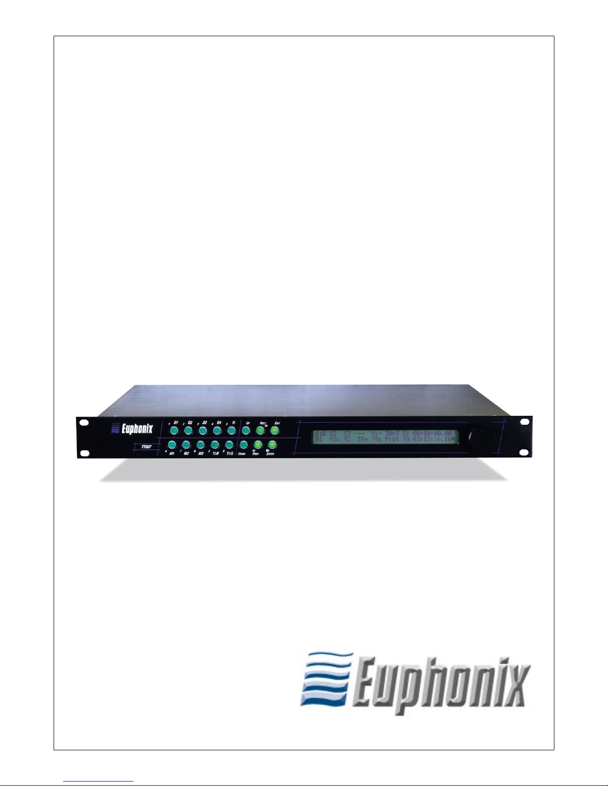
Euphonix TT007
Machine Control Hub for System 5
and CS Series Consoles
Operation Manual
Document Revision: 2.0
Release Date: February, 2002
TT007 Version: 4
Part Number: 840-05044-03
Euphonix Inc.
220 Portage Ave.
Palo Alto, California 94306
Phone: 650-855-0400
Fax: 650-855-0410
Web: http://www.euphonix.com
e-mail: info@euphonix.com
Page 2

In the interest of continued product development, Euphonix reserves the right to make
improvements in this manual and the product it describes at any time, without notice or
obligation.
System 5, S-5, PatchNet, eMix, EuCon, R-1, Audio Deck, Studio Hub are trademarks of
Euphonix Inc.
©2001 Euphonix Inc. All rights reserved worldwide. No part of this publication may be
reproduced, transmitted, transcribed, stored in a retrieval system, or translated into any
language in any form by any means without written permission of Euphonix Inc.
Page 3

Euphonix TT007 Operation Manual
Table of Contents
List of Figures
List of Tables
Chapter 1: Overview
.........................................................................................................................v
......................................................................................................................... vi
..........................................................................................................7
1.1 Introduction..................................................................................................7
1.2 Navigating the Front Panel ..........................................................................8
Chapter 2: TT007 Menu Modes
2.1 Port Mode Menu ........................................................................................11
2.1.1 Machine Menu ...............................................................................12
2.1.2 TimeLine Lynx Network Support..................................................14
2.1.3 Connecting Controllers to the TT007 ............................................15
2.2 Sync Mode Menu.......................................................................................16
2.3 Utility Mode Menu ....................................................................................17
2.4 Presets Mode Menu ...................................................................................19
..................................................................................11
2.5 Transport Mode Menu ...............................................................................21
Chapter 3: Configurations
3.1 Euphonix as Master Machine ....................................................................23
3.1.1 LTC ................................................................................................23
3.1.2 Serial ..............................................................................................24
3.1.3 MIDI...............................................................................................24
3.1.4 LTC/Serial/MIDI ...........................................................................25
3.2 Euphonix As Slave Machine......................................................................25
3.2.1 Serial ..............................................................................................25
3.2.2 Large Network (Serial/MIDI/LTC) ...............................................26
3.3 TcR as Master with Serial Control ............................................................27
3.4 LynxNET as Master...................................................................................28
...........................................................................................23
iii
Page 4

Euphonix TT007 Operation Manual
Appendix
29
A.1 Frequently Asked Questions......................................................................29
A.2 Explanation of Controllers.........................................................................30
A.2.1 Examples of Devices, Controllers, and Emulators ........................31
A.3 MIDI Operation with Pro Tools.................................................................34
A.3.1 OMS MIDI Setup...........................................................................34
A.3.2 Pro Tools as Master........................................................................35
A.3.3 Pro Tools as Controller ..................................................................36
A.4 9-Pin Operation with ProTools ..................................................................37
A.4.1 OMS Setup.....................................................................................37
A.4.2 ProTools (9-pin Remote) as a Serial Master or Slave....................37
A.5 Operation with a 3324, 3348, or 3348HR..................................................39
A.6 Cable Pinouts .............................................................................................41
iv
Page 5

Euphonix TT007 Operation Manual
List of Figures
1-1 TT007 front and rear panels.................................................................................................7
1-2 Front panel with Port Assignments Display ........................................................................8
1-3 TT007 Menu Modes ............................................................................................................9
2-1 Port Assignments for Time Lynx Network........................................................................14
2-2 Front panel usage ...............................................................................................................17
2-3 TT007 preset examples ......................................................................................................20
3-1 LTC Master parameter setting and configuration..............................................................23
3-2 Video machine slaved to Euphonix console ......................................................................24
3-3 Audio Workstation slaved to Euphonix console................................................................24
3-4 Audio Workstation, video deck, and hard-disk recorder slaved to Euphonix console ......25
3-5 Euphonix console slaved to video machine.......................................................................25
3-6 Euphonix console slaved in a large network .....................................................................26
3-7 TcR as Master ....................................................................................................................27
3-8 LynxNet as Master.............................................................................................................28
A-1 TT007 as controller............................................................................................................31
A-2 TT007 as device ................................................................................................................32
A-3 TT007 as secondary controller .........................................................................................32
A-4 TT007 as multiple controller hub ......................................................................................33
A-5 OMS MIDI Setup...............................................................................................................34
A-6 OMS Studio Setup and MIDI Device Info dialogs............................................................34
A-7 Synchronization tab in the Pro Tools Peripherals dialog...................................................35
A-8 MIDI Controllers tab in the Pro Tools Peripherals dialog.................................................36
A-9 Pro Tools Transport Controls ............................................................................................36
A-10 Machine Control tab in the Pro Tools Peripherals dialog..................................................37
A-11 Pro Tools Remote Mode 9-pin cable .................................................................................38
A-12 Cable pinout diagrams .......................................................................................................41
v
Page 6

Euphonix TT007 Operation Manual
List of Tables
2-1 Port Modes...................................................................................................................... 12
2-2 Sync Modes..................................................................................................................... 16
2-3 Function and LCD symbols for front panel keys ........................................................... 21
A-1 Devices and Controllers.................................................................................................. 31
vi
Page 7
Euphonix TT007 Operation Manual
Chapter 1: Overview
1.1 Introduction
The TT007 is an optional rack-mount device that provides machine control for all Euphonix consoles. The TT007 allows the console to become the single, centralized machine control hub within any studio. Virtually every machine, in or out of the control
room, can be remotely controlled from the console at the press of a button. The flexibility gained from the addition of the TT007 is unprecedented. These are a few of the
many features that can be seamlessly implemented with the TT007:
• Entire machine networks can be configured and set into motion directly from
the console.
• user nameable, instantly accessible locate points
• automatic transport cycling
• jogging and variable shuttle
• control tape decks, DAWs, and other synchronizers
All timecode formats and frame rates are supported, including MIDI Time Code (MTC)
and external video sync. MIDI Machine Control (MMC), the TimeLine Lynx™ network, and Sony 9-pin (P2) protocols work right “out of the box” to insure that starting
to work with the TT007 is quick and easy. Three MIDI and three serial machine ports
are available. The TT007 also has a built-in timecode generator and LTC reader.
Timecode
Preset #
O
UT
O
UT
Timecode
Readouts
Format
I
N
N
TR I
I
N
Timecode Reader
(TR In)
Transport Status Icon
TR I
N
TG O
T
I
MECODE
Timecode Generator
(TG Out)
TG O
UT
UT
Data Wheel
AC I
NPUT
100V TO 260
50 TO 60 H
O
I
V
Z
VIDEO
OUT TC
WINDOW
IN
OUT TC
WINDOW
Video In
Video Out/Thru
E
XIT
LCD Display
S1s S2 S3 -- Vi- 30:S TG 00:50:02:06
M1s M2c M3 TR TG P:01 M2 00:50:02.06
M 2 M 3
NOUT
I
I
NOUT
I
N
O
UT
I
N
O
UT
MIDI Ports (M 1-3)
Port keys Menu keys
I
V
S3S2
4
3762
TCR
M3M2M1
S 2 S 3
S 2 S 3S 1
PC
5
098
TCG
Expansion Port
TT007
UPN
EXT
>>
<<0>
E
NTER
D
OWN
P
REV
MIDI M1
S 4
S 4
S1
1
TT007
IN
SYNC
RS422
SYNC
S 1
Serial Ports (S 1-3)
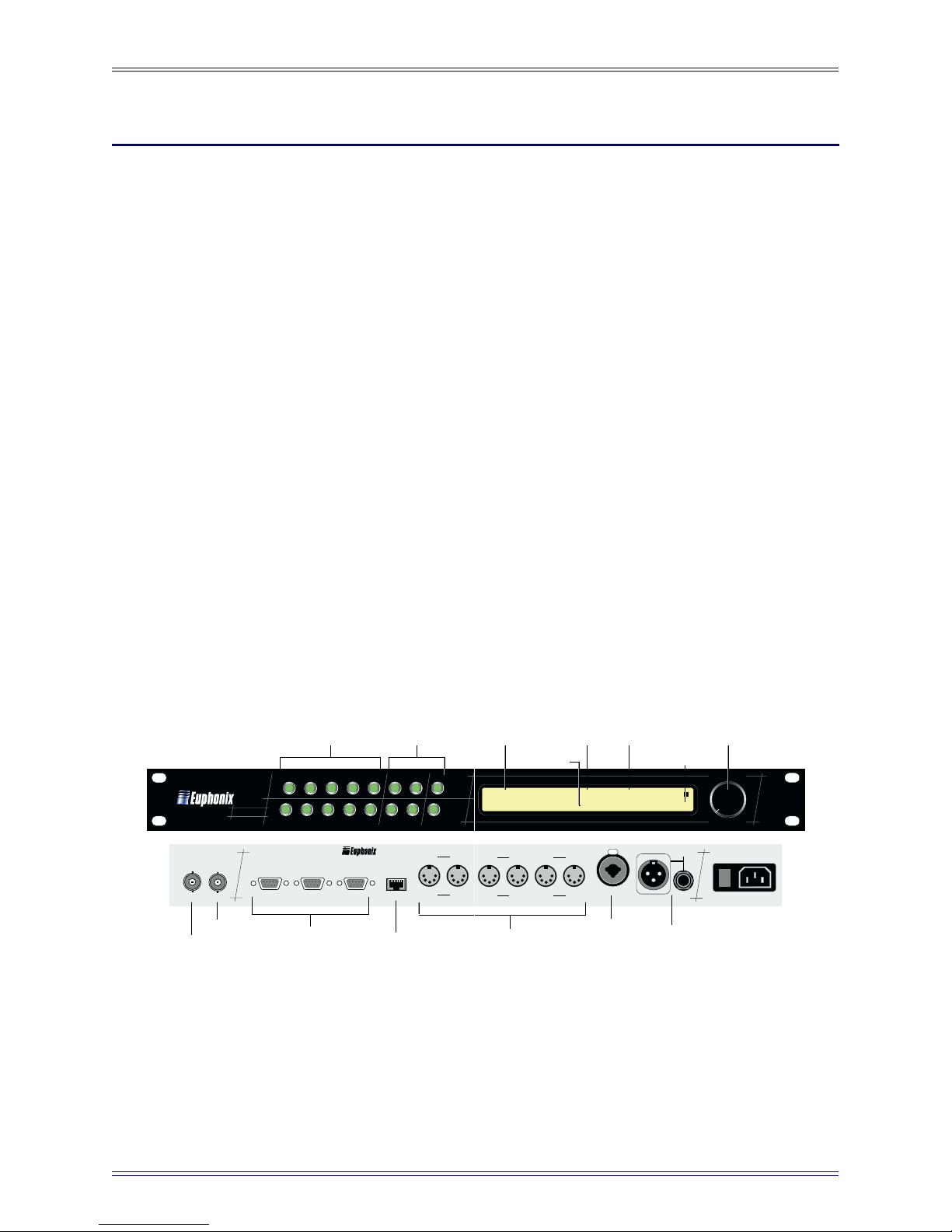
The TT007’s front panel is very easy to master. Dedicated Port buttons instantly access
individual assignments for each machine control Port. Any Port can be defined as a
master, controller, or slave. A single master acts as the synchronization source for all
machines in the network.
Figure 1-1 TT007 front and rear panels
7
Page 8
Euphonix TT007 Operation Manual Overview
The transport controls of the master machine can drive the network but the TT007 is
unique in its ability to accept transport commands from additional control surfaces and
relay those commands to the master machine. Any controller device in the studio (System 5, CS3000/CS2000, DAW, Sequencer, etc.) defined as a controller (and on-line)
has direct access to the master machine. This gives the engineer new freedom to issue
commands from the most convenient place in the studio at any given moment: Hit Play
on the sequencer, turn around and press Stop on the workstation to make an edit, then
pull forward and hit Play on the console to continue the mix!
The built-in SMPTE/EBU generator can supply the master timecode source when random
access machine control is desired, or for machines unable to generate their own timecode. Two readouts on the front panel LCD display incoming timecode from any selected Port. Additionally, a video burn-in window can be set to display one of the eight
available timecode sources. The burn-in window can be superimposed on a video monitor
by simply passing a composite video signal through the TT007 video reference input.
The TT007 stores 50, user-defined presets that are instantly recalled when needed. The
presets store customized machine control configurations including Port configurations,
timecode formats, sync preferences, and window displays.
The transport controls on the TT007 are similar to most tape machines: Play, Stop, Fast
Forward and Rewind are all clearly marked on the front panel. Transport mode allows
control of any one of the seven ports or the timecode generator from the transport keys
and the front panel Data Wheel.
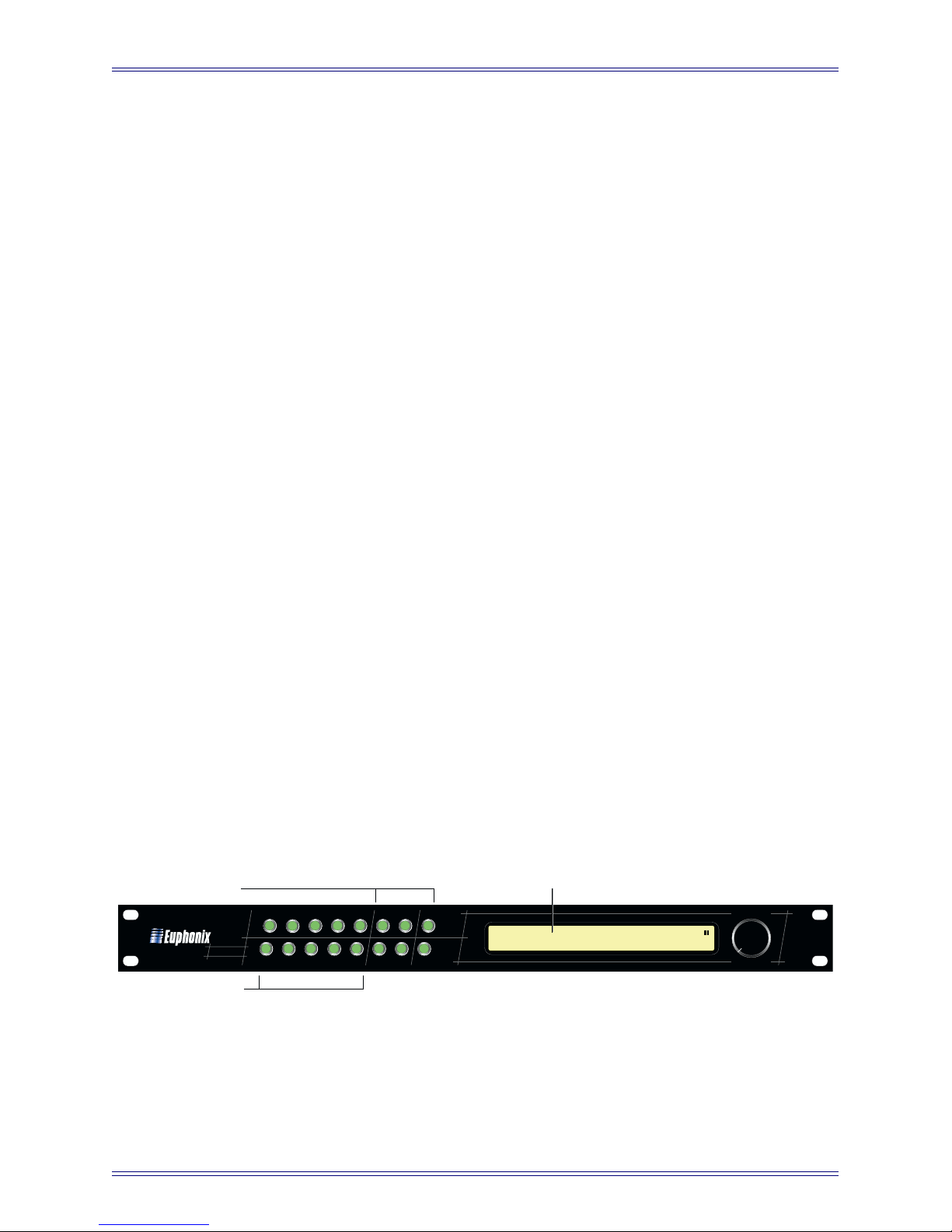
1.2 Navigating the Front Panel
Navigating the TT007’s front panel and menu system is easy after you familiarize
yourself with a few basics. The front panel has two rows of green buttons. The first
10 are dedicated Port Keys. The last six are Menu/Transport keys: they move through
the menu tree and change parameter values and then act as transport buttons when in
Transport Mode.
Port Assignments Display
Menu Keys
TT007
I
V
S1
1
PC
S3S2
5
4
3762
098
TCR
TCG
M3M2M1
D
OWN
U
P
N
EXT
<<0>
P
REV
E
XIT
>>
E
NTER
(Default Screen)
S1s S2 S3 -- Vi- 30:S TG 00:50:02:06
M1s M2c M3 TR TG P:01 M2 00:50:02.06
Port Keys
Figure 1-2 Front panel with Port Assignments Display
8
Page 9

Euphonix TT007 Operation Manual Overview
When the TT007 boots up, the first screen visible is the Port Assignments Display, which
is the default screen. Press the EXIT key from this screen to display the TT007’s ROM
version number. Press the EXIT key one or more times from any other display (depending on the depth within the menu system) to restore the Port Assignments Display.
The Port Assignments Display shows the status of all ports, as well as the current
SMPTE/EBU frame rate and synchronization reference. The two timecode readouts on
the right remain visible at all times regardless of the current mode or menu level. The
Port name to the left of each timecode window identifies its source. A single character
at the far right of the LCD display shows the current transport status (Play / Stop / Rew
/ FF / Shuttle) for the displayed Port.
From the Port Assignments Display, press the Enter key to select the Menu mode.
Port Assignments Display
(Default Screen)
Port Mode Menu Sync Mode Menu Utility Mode Menu Presets Mode Menu Transport Mode Menu
Figure 1-3 TT007 Menu Modes
The PREV and NEXT keys scroll through the list of menus. Press ENTER to confirm
the current selection and display that mode’s menus. Press EXIT to return to the Port
Assignments Display. The UP and DOWN keys light when they can select parameter
settings. In general, the PREV and NEXT keys scroll through parameters and lists and
the UP and DOWN keys select a specific value for the parameter. The PREV/NEXT
and UP/DOWN keys light in each context to guide you through the selection process.
The Data Wheel performs the same function as the currently lit keys: Rotate the Data
Wheel counterclockwise for PREV or DOWN and clockwise for NEXT or UP.
Chapter 2: TT007 Menu Modes discusses the five mode menus in detail.
Chapter 3: Configurations discusses common TT007 configurations.
9
Page 10

Page 11

Euphonix TT007 Operation Manual TT007 Menu Modes
Chapter 2: TT007 Menu Modes
2.1 Port Mode Menu
To access Port Mode from the Port Assignments Display:
1. Press any Menu key.
2. Scroll through the list with the PREV and NEXT keys until PORT MODE is
displayed.
3. Press the ENTER key.
You can also press any of the dedicated, front panel Port keys. Depending on the Port being
viewed, the display shows a different status to indicate that Port’s current assignment.
The possible assignments are:
Off
Port is inactive (off-line).
Controller
Port can pass both synchronization data and transport commands (FF, Rew, Stop, etc.)
to/from the connected device. Transport commands relayed from the device, are returned
to the Master Port. See Section A.2 - Explanation of Controllers for more information.
Slave
Port passes only synchronization data (timecode) to the connected device.
Master
Sets port as the master synchronization source for the entire system. Any timecode sync
source from the Master device will be transmitted to all other TT007 ports selected as
either Slave or Controller. The Master device’s transport may be controlled locally via
its own front panel or remotely via other controller devices attached to the TT007.
The PREV and NEXT keys scroll through the Port list. The UP and DOWN keys (or
the Data Wheel) select assignment options. Pressing EXIT returns to the default display.
ENTER has no function in this menu.
NOTE: Selecting a Port as Master forces any previous Master Port selection off-line. Designating
a Master is immediate when selected in the Port menu. If the TT007 is configured
without a Master Port, the EXIT and ENTER keys flash alternately to alert the user
that no Master Port has been defined for this preset.
11
Page 12
Euphonix TT007 Operation Manual TT007 Menu Modes
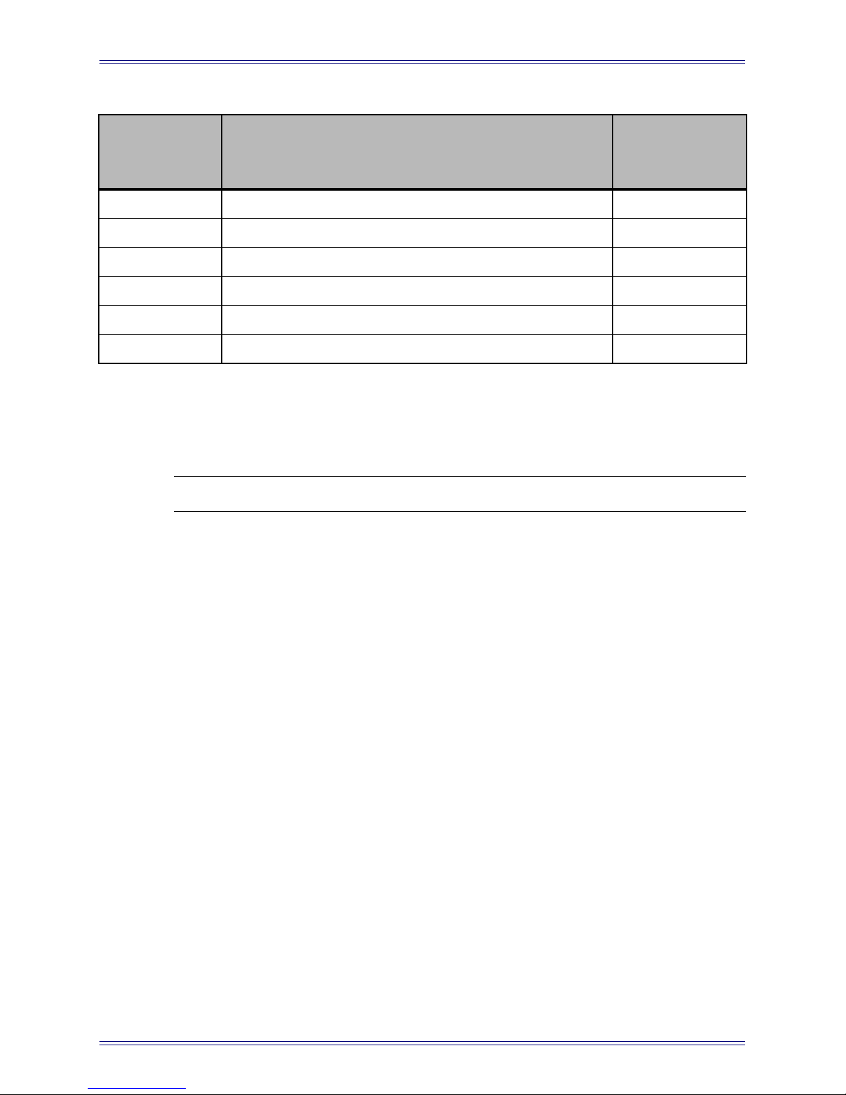
Table 2-1 Port Modes
Symbol in Port
Port Available assignments
Assignments
Display
M1-M3 OFF / Controller / Slave / Master c / s / M
S1-S3 OFF / Controller / Slave / Master c / s / M
S1 (additional) LynxNET (Master) / Lynxnet (Slave) / EsBUS* / A-Smith T / t / E / A
TcG OFF / Slave / Master s / M
TcR OFF / FromMaster** / Master m / M
Resolve (Vi) VIDEO / Free run R / –
* Proprietary protocol for Studer D820 and D827 control
** Timebase synchronization is based on LTC signals received at the TcR Port. Longitudinal Time
Code (LTC) signals are typically audio reference tracks on the Master machine.
NOTE: The TT007’s TcG should always be set to Slave if not selected as Master.
2.1.1 Machine Menu
Pressing a Port key twice accesses the Machine Menu. The first press displays the Port
Menu screen; the second press displays the Machine Menu. In the Machine Menu, the
PREV and NEXT keys scroll the available parameters, which vary based on whether
the Port is configured as a Master or Slave:
Record
OFF Safe (Recording disabled)
EDIT Insert recording over audio tracks only
ASSEMBLE Overwrite sync track, video, and audio tracks
Track Arm
OFF No Track Arming Request is translated to port
ON Any analog or digital Track Arm Request is translated to port
D=A Converts analog Track Arm Requests to equivalent Digital Requests
48 no tally For use with Pro Tools. Since Pro Tools does not output track tallies
when in record, the tallies generated by the TT007 are not current if
track arming is changed while Pro Tools is in motion; they are just
the last known state.
12
Page 13

Euphonix TT007 Operation Manual TT007 Menu Modes
Stop
Still Translates Stop commands to device as Still
Stop Translates Stop commands to device as Stop
Standby Translates Stop commands to device as Standby
Stop vs. Still or Standby commands are used by some hard disk machines, (such as Radar
and Fairlight), to determine whether the device should return to input when parked.
Type (Master)
Normal
TC in Play For non-video resolved machines
Code only Uses wind commands to locate for machines with no timecode reader
MMC Standard MIDI Machine Control
MTC Only Uses MTC only to determine status for systems that do not respond
to MMC information requests (i.e., Pro Tools). Additionally, the
punch IN and punch OUT commands are continuous controllers.
Type (Slave)
Slow Shtl U-matic, etc.
Med Shtl D1, D2, Beta, etc.
Hard Disk V1, etc.
Slow Vari
Tape DAxx DA88, DA98, etc.
Tape 33xx 324, 3348, 3348HR, etc.
Selecting the proper machine type for each serial Slave port provides a fast and reliable
lock between device machines. The Type sub-menu provides a list the most commonly
used device types. Determine the type that best matches the ballistics of the machine
connected to this particular Port. Older U-matic video decks should be set to Slow Shtl.
Newer D2 and Beta video machines can be set to Med Shtl.
Offset (slave/TcG)
Use this field to set positive or negative TC offsets for any serial Slave device. The data
wheel is used to set the desired offset. The UP and DOWN keys select between HH,
MM, SS or FF. Data entry is immediate so there is no need to confirm an offset value.
Offsets may also be trimmed on the fly. Press the ENTER key to clear the current offset.
The Timecode Generator (TcG) can have an offset even when configured as Master.
This is helpful when striping timecode starting at a time other than 00:00:00.00.
13
Page 14

Euphonix TT007 Operation Manual TT007 Menu Modes
Generator
Gain +9 to -24 dB in 3-dB steps
Burst Selects the number of frames to output during serial Rew/FF and lo-
cate commands
Delay For Euphonix diagnostics use only: should be set to OFF
2.1.2 TimeLine Lynx Network Support
In addition to its own network of devices, the TT007 may also be integrated with a
TimeLine Lynx machine control network. The S1 Port connects as the Lynx Network
controller where it can command any combination of the eight machines on the Lynx
network.
The Port Assignment menu for S1 has three additional settings (besides the standard
Controller / Slave / Master). Scroll to the LynxNET setting using the UP and DOWN
keys or the Data Wheel, then press the S1 Port key a second time to enter the TimeLine
Network configuration menu. A master machine must be selected from one of the eight
displayed addresses. Additional machines may be selected into the on-line group as
desired. All selections for the TimeLine Network menu are stored within a preset, so
selecting groups of machines in any combination is fast. Simply recall the desired preset
to reconfigure the entire network.
Select the Master machine (1-8) by pressing the corresponding numbered Port key.
Display the Select page with the PREV and NEXT keys or Data Wheel, then use the
Port/number keys again to bring other machines on-line.
Master
On-Line (Selected)
1 2M 3 4. 5. 6. 7 8 S1 00:00:00.00
Master ["Lynx" NET ]M2 00:00:00.00
Use the [
PREV] and [NEXT>>
] keys or Data
<<
Wheel to toggle between "Master" and
"Select" pages.
Figure 2-1 Port Assignments for Time Lynx Network
14
Page 15

Euphonix TT007 Operation Manual TT007 Menu Modes
2.1.3 Connecting Controllers to the TT007
The TT007 serial ports (S1, S2, S3) are wired so they can be cabled directly to devices.
When connecting an additional controller to the network, the transmit (Tx) and receive
(Rx) pins of the RS-422 interconnect cable must be reversed to enable the TT007 to emulate a device and translate controller commands to the network.
The pinout for such a cable is shown in Figure A-12 on page 41.
15
Page 16

Euphonix TT007 Operation Manual TT007 Menu Modes
2.2 Sync Mode Menu
Sync Mode is used to set basic synchronization parameters, such as frame rate and
clock reference. To access the Sync Mode from the Port Assignments Display:
1. Press any Menu key.
2. Scroll through the list with the PREV and NEXT keys until SYNC MODE is
displayed.
3. Press the ENTER key.
The PREV and NEXT keys scroll through the list of selections. The UP and DOWN
keys and the Data Wheel change the setting.
Table 2-2 Sync Modes
Parameter Value Description
Free Run Internal Clock Reference -
Resolve
Video Sync to External Video Reference R
ON TT007 automatically selects the frame
TC Detect
Frame Std
Video Std
LEDs
OFF Frame rate auto-sensing is disabled
24:FILM Film 24:F
25:EBU EBU 25:E
30:DF SMPTE (Drop frame) 30:D
30:SMPTE SMPTE (Non-drop) 30:S
NTSC
PAL
Comms Port Keys light to indicate communica-
Locking Port Keys light to indicate synchronization
rate to match incoming timecode (default)
tions with attached devices
lock with attached devices
LCD
Symbol
OFF Slaves not relocked if they lose lock
Relock
ON Slaves re-lock if they lose lock
OFF
MTC Stop
ON
16
Page 17

Euphonix TT007 Operation Manual TT007 Menu Modes
2.3 Utility Mode Menu
Utility Mode is used to configure the TT007’s user interface options. All timecode
display windows and Data Wheel functions are configured from this menu. To access
the Utility Mode from the Port Assignments Display:
1. Press any Menu key.
2. Scroll through the list with the PREV and NEXT keys until UTILITY MODE
is displayed.
3. Press the ENTER key.
SERVICE
RESET TT Soft system re-boot
MEM CLEAR Clears presets to factory defaults and erases any RAM-based OS
BURNIN TC
BURN-IN TC (Src) Selects Port for on-screen display
Column (0-219) Moves burn-in from left to right on-screen
Line (0-139) Moves burn-in up and down on-screen
Size/Mode (OFF, 1-8) Selects display format for burn-in
Bottom TC
Selects source Port for lower TC display in LCD window.
Top TC
Selects source Port for upper TC display in LCD window.
SHORTCUT: Pressing the UP or DOWN keys while holding any Port key displays that Port in
the top or bottom LCD timecode readout, respectively (see Figure 2-2).
Step 1: Hold desired Port key
Step 2: Press to display here
S1
1
TT007
I
V
PC
S3S2
5
4
3762
098
M3M2M1
TCR
TCG
D
OWN
U
P
<<0>
E
XIT
N
EXT
>>
S1s S2 S3 -- Vi- 30:S TG 00:50:02:06
E
NTER
P
REV
M1s M2c M3 TR TG P:01 M2 00:50:02.06
Step 2: Press to display here
Figure 2-2 Front panel usage
17
Page 18

Euphonix TT007 Operation Manual TT007 Menu Modes
NudgeMode Select
In Transport Mode, the Data Wheel functions as:
JOG Jog Wheel (movement in single-frame steps)
SHUTTLE Shuttle Wheel (scan speed control)
CS3000/2000 owners: From the DSC, enter Jog by toggling the [<>] key until it flashes.
Enter Variable Shuttle by toggling the [<>] key until it is solid. Both functions use the
Spin Knob as the machine control interface when active.
WindSpeed Adjust
Selects scan speed rate in the range 001–010. This setting applies to machines that support a threaded (heads engaged) vs. unthreaded (heads disengaged) wind mode. The
higher the WindSpeed number, the faster the machine will scan in threaded wind mode.
This setting is stored with the Preset.
If set OFF, FF and Rew commands are always unthreaded. If set to any non-zero value,
the first press of a FF or Rew key initiates a threaded wind (scan). A second press of the
same key initiates an unthreaded wind. A third press of the same key toggles back to a
threaded wind, etc.
REV Play
OFF Reverse Play disabled
ON Reverse Play enabled; press Play immediately after Rew to initiate
Reverse Play
REC Safe
This is the global master Record Safe switch for the TT007 and all ports are configured
by this selection:
OFF Record Ready; any port may receive Record commands
ON All Safe Mode; record commands will not pass out to any device
Re-Direct
Selects a port, other than the Master, to receive track arming and record commands:
OFF
M1
M2
M3
S1
S2
S3
18
Page 19

Euphonix TT007 Operation Manual TT007 Menu Modes
2.4 Presets Mode Menu
Presets Mode is very powerful for users who require flexibility in machine control setups. Up to 50 presets can store different port assignment configurations. Each preset
can be named for easy identification.
To access the Presets Mode from the Port Assignments Display:
1. Press any Menu key.
2. Scroll through the list with the PREV and NEXT keys until PRESETS is
displayed.
3. Press the ENTER key.
Presets Mode has three functions:
Recall Recalls currently selected preset number upon pressing ENTER
Rename Renames the current RAM preset
Store Stores the current configuration into the selected preset number
upon pressing ENTER
Recalling a Preset
Select Recall with the PREV and NEXT keys. Use the Data Wheel to select the desired
preset by name or preset number. Confirm the selection and recall the preset with the
ENTER key.
SHORTCUT: Use the Port keys as a fast way to access presets. From the Recall Menu, press
a Port key to recall the corresponding Preset number (1-10).
Renaming a Preset
Select Rename with the PREV and NEXT keys. Use the UP and DOWN keys to move
the cursor and the Data Wheel to change the selected character. There is no need to
confirm the new name; ENTER has no function in this screen.
Renaming affects only the current preset in RAM. A renamed preset may be stored to
its original preset number or another location using the Store function.
Storing a Preset
Select Store with the PREV and NEXT keys. Use the Data Wheel to select the desired
preset number, then press ENTER to select that number. You will then be asked to
confirm the selection by pressing the UP key. The current configuration is written to
the selected location in RAM (battery backed-up).
19
Page 20

Euphonix TT007 Operation Manual TT007 Menu Modes
Individual machines may be controlled independently simply by creating presets that
identify only a single port. Groups of machines may be configured in the same manner.
Those presets may then be instantly recalled from the console to control the entire network, a group, or individual machines.
NOTE: Turning on MSTR CTRL recalls the current preset number lit on the DSC. Any TT007
configuration not saved to a preset will be lost.
Figure 2-3 shows some examples of TT007 preset setups.
Preset #1 - S1M
DA-88
Preset #4 - S1M - S2s - S3s
Preset #2 - S2M Preset #3 - S3M
DA-98
BVW-75
Preset #5 - S1s - S3M
BVW-75DA-98DA-88
DA-98
BVW-75
Preset #6 - TGM
Synclavier
Figure 2-3 TT007 preset examples
20
Page 21

Euphonix TT007 Operation Manual TT007 Menu Modes
Parameters Stored in Presets
• Port Assignments (Master, Controller, Slave, LynxNET, EsBUS)
• LynxNET Master and On-line selections
• Video Reference (Resolve/Free run)
• Timecode Frame rate
• Video Standard
• Port selections for LCD Window timecode displays
• Burn-in Window Port selection
• Master Port Record Mode (Edit/Assemble/OFF)
• Slave Port Type
• Slave and Master Offset values
2.5 Transport Mode Menu
Any machine in the network can be controlled from the TT007’s front panel. To access
the Transport Mode from the Port Assignments Display:
1. Press any Menu key.
2. Scroll through the list with the PREV and NEXT keys until TRANSPORT
MODE is displayed.
3. Press the ENTER key.
When the Transport Mode is entered, the Port currently defined as Master is automatically selected. The Menu keys have the functions shown in Table 2-3. The machine’s
transport state is indicated to the right of the timecode display.
Table 2-3 Function and LCD symbols for front panel keys
Key Function
ENTER Play / Stop ! / !
<< Rewind / Scan
>> Fast Forward / Scan
LCD
Symbol
!
/
«
/ "
»
Data Wheel Jog / Shuttle ! or "
21
Page 22

Page 23

Euphonix TT007 Operation Manual
Chapter 3: Configurations
Before attempting to synchronize multiple machines, you must:
• be familiar with all basic TT007 functions discussed in the previous sections;
• have a basic understanding of synchronization and machine control.
3.1 Euphonix as Master Machine
In the recording industry, many devices cannot generate their own timecode and rely
on incoming LTC to synchronize. The many workstations, sequencers, consoles, and
automation systems that fall into this category are known as code-only slaves. A problem
arises when neither the audio source nor the mixing console can generate timecode. The
solution is to add a third machine with the sole function of providing timecode to the
other two devices.
Both the System 5 and CS3000/2000 series consoles are designed to control the TT007
as a seamless extension of the Euphonix system. All TT007 functionality is available
to the mixer as if it were actually embedded in the console. In such a situation, the
console becomes a virtual machine.
3.1.1 LTC
A simple application for this additional functionality uses the Euphonix system to
generate LTC. To use the Euphonix system as the LTC master, consult Figure 3-1 for
parameter settings and configuration.
Video Sync
Generator
S1 S2 S3 -- ViR 30:S
M1 M2c M3 TR TGM P:01
DSC: MstrCtrl=On TC Slave=Off Machine Select=1
Video
Video
Out
S1 S2 S3 (S4)
In
(factory default Preset #1)
M2
M1 M3
MIDI Out
MIDI In
LTC
In
LTC
Out
Audio Workstation
Figure 3-1 LTC Master parameter setting and configuration
Notice that the console is connected to the M2 Port; this is a standard system connection.
By default, every TT007 preset pre-assigns M2 as a controller so the console is always
on-line and able to drive the machine control system.
Euphonix Console
23
Page 24

Euphonix TT007 Operation Manual Configurations
3.1.2 Serial
Synchronizing audio and video is a common and useful application for the TT007. The
Euphonix machine control system can access three separate video decks using standard
Sony P2 serial control. The following preset slaves a video machine to Euphonixgenerated timecode connected on S1.
3.1.3 MIDI
Many sequencers use MIDI Machine Control (MMC) and MIDI Time Code (MTC) for
synchronization instead of SMPTE/EBU timecode. The Euphonix system provides a
tremendous benefit to a studio by converting SMPTE/EBU to MTC, which allows
MTC machines to follow SMPTE/EBU synchronization networks. Figure 3-3 shows
how to slave an Audio Workstation on the M1 port to the Euphonix System.
S1s S2 S3 -- ViR 30:S S1 00:18:01:06
(factory default Preset #2)
M1 M2c M3 TR TGM P:02 M2 00:18:01.06=
DSC: MstrCtrl=On TC Slave=Off Machine Select=2
To
Video Display
Monitor
Video Sync
Generator
Figure 3-2 Video machine slaved to Euphonix console
Video
Video
Out
Video Deck
S1 S2 S3 (S4)
In
M2
M1 M3
MIDI In
MIDI Out
Euphonix Console
LTC
In
LTC
Out
S1 S2 S3 -- ViR 30:S S1 00:18:01:06
M1s M2c M3 TR TGM P:03 M2 00:18:01.06=
DSC: MstrCtrl=On TC Slave=Off Machine Select=3
Video Sync
Generator
* Video Sync is optional
Figure 3-3 Audio Workstation slaved to Euphonix console
Video
Out
Video
In
Audio Workstation
S1 S2 S3 (S4)
24
(factory default Preset #3)
LTC
M2
M1 M3
MIDI In
MIDI In
MIDI Out
MIDI Out
Euphonix Console
LTC
In
Out
Page 25

Euphonix TT007 Operation Manual Configurations
3.1.4 LTC/Serial/MIDI
The Euphonix system can control a group of slave machines as easily as a single slave.
Figure 3-4 shows three machines slaved to the Euphonix system simultaneously.
S1s S2 S3 -- ViR 30:S S1 00:18:01:06
M1s M2c M3 TR TGM P:04 M2 00:18:01.06=
(factory default Preset #4)
DSC: MstrCtrl=On TC Slave=Off Machine Select=4
To
Video Display
Monitor
Video Sync
Generator
Video
Out
Video Deck
Video
In
S1 S2 S3 (S4)
Hard Disk
Recorder
M2
M1 M3
MIDI In
MIDI In
MIDI Out
MIDI Out
LTC
LTC
In
Out
Audio Workstation
Euphonix Console
Figure 3-4 Audio Workstation, video deck, and hard-disk recorder slaved to Euphonix console
3.2 Euphonix As Slave Machine
3.2.1 Serial
Most video post applications prefer using the video machine as the master sync source.
The Euphonix system can easily slave to serial timecode on any of its 9-pin Ports.
Preset 5 configures the S1 Port as Master (Figure 3-5).
S1M S2 S3 -- ViR 30:S S1 00:18:01:06
M1 M2c M3 TR TGs P:05 M2 00:18:01.06=
DSC: MstrCtrl=On TC Slave=Off Machine Select=5
To
Video Display
Monitor
Video Sync
Generator
Video
Out
Video Deck
Video
In
S1 S2 S3 (S4)
Figure 3-5 Euphonix console slaved to video machine
(factory default Preset #5)
LTC
M2
M1 M3
MIDI In
MIDI Out
Euphonix Console
LTC
In
Out
Audio Workstation
25
Page 26

Euphonix TT007 Operation Manual Configurations
X
In addition to simply slaving to timecode, however, the Euphonix system can also act
as the machine transport controller for the Master video deck. Even though the Euphonix
console is a slave to incoming timecode, it can still use its transport controls to drive the
master machine. Play/Stop/Locate commands issued from the console are received by
the master synchronization device, which then sends timecode to all machines on the
network. This is extremely powerful because all the console’s locate functions are
available for every machine in the studio without having to move from the console:
named locate points, automatic cycling, jog, variable shuttle, threaded vs. unthreaded
winding, and remote punch-ins.
3.2.2 Large Network (Serial/MIDI/LTC)
Figure 3-6 shows a typical large-scale installation that demonstrates the power of a
Euphonix studio.
S1M S2c S3s -- ViR 30:S S1 00:18:01:06
M1s M2c M3c TR TGs P:06 M2 00:18:01.06=
(factory default Preset #6)
DSC: MstrCtrl=On TC Slave=Off Machine Select=6
MIDI
Video Display
Video Sync
Generator
To
Monitor
Video
Out
Video Deck
Audio Workstation
Video
In
MDM Recorder
S1 S2 S3 (S4)
DAT Machine
MIDI In
MIDI Out
MIDI In
M2
M1 M3
MIDI In
MIDI Out
Euphonix Console
MIDI Out
LTC
In
Sequencer
LTC
Out
Sound F
Sampler
Figure 3-6 Euphonix console slaved in a large network
Note that S2 is a controller, which means that not only does it chase the serial timecode,
but it also sends machine control commands to the master. M3 is also a controller,
which provides control to the network operator from four locations: the master deck,
the Euphonix console, the dialog workstation, or the music sequencer.
26
Page 27

Euphonix TT007 Operation Manual Configurations
3.3 TcR as Master with Serial Control
Many older video decks do not provide timecode on their serial control cable, which is
used only for machine control. The Euphonix system allows these machines to act as
the Master by reading its audio LTC timecode track at the TcR Input Port.
S1M S2 S3 -- ViR 30:S
M1 M2c M3 TRm TGs P:04
DSC: MstrCtrl=On TC Slave=Off Machine Select=Setup Required (1-6)
To
Video Display
Monitor
Video
Out
Video
In
S1 S2 S3 (S4)
M2
M1 M3
LTC
In
LTC
Out
MIDI In
Video Sync
Generator
Video Deck
MIDI Out
Euphonix Console
Figure 3-7 TcR as Master
Play/Stop/FF/Rew commands are issued to the master machine via the 9-pin connection,
and the synchronization timecode is then sent back from the TcR Port. This configuration
is also useful when regenerated (offset) code is desired as the synchronization source.
The From Master option on the TT007 allows reading code from MIDI Masters when
LTC has been recorded on an audio track of an editor or MDM.
27
Page 28

Euphonix TT007 Operation Manual Configurations
3.4 LynxNET as Master
The Euphonix system can address eight machines using the TimeLine Lynx protocol.
S1 can be configured as the interface Port to the LynxNET. Any machine on the LynxNET may be assigned as Master for the entire TT007. We recommend that the master
Lynx module feed timecode to the TcR Port using the From Master option to ensure
accurate synchronization if video is not present.
S1T S2 S3 -- Vi 30:S
M1 M2c M3 TRm TGs P:05
DSC: MstrCtrl=On TC Slave=Off Machine Select=Set-up Required (1-6)
Video
Video
Out
Video Sync
Generator
* Video Sync is optional
Lynx
Network
Figure 3-8 LynxNet as Master
S1 S2 S3 (S4)
In
Lynx Module
M2
M1 M3
MIDI In
MIDI Out
Euphonix Console
LTC
In
LTC
Out
28
Page 29

Euphonix TT007 Operation Manual
Appendix
A.1 Frequently Asked Questions
Why does my TC generator not run when I hit play?
• It is not configured as a Master or Slave.
• It is set to video resolve but no video sync is being received
Why does the master machine selection keep shutting off?
There can only be one master machine, so when you configure a new port as Master,
any port previously designated as Master automatically toggles OFF. This may happen
unintentionally while passing through the master selection for a port while intending to
configure it for some other setting.
Why does the video sync selection keep shutting off?
The TcR (Timecode Reader) and Video sync are mutually exclusive, i.e., the TT007
can only use one of them as a reference. When either is selected, the other automatically
toggles OFF.
Why does the TC reader keep shutting off?
See above.
What is the difference between a Master, Slave and Controller?
See Explanation of Controllers on page 30.
Why are my presets gone?
Replacing the system software Eprom and/or selecting MEM CLEAR from the Service
submenu erases system presets.
Why is there no timecode at the desk but I see it on the TT007 display?
The Timecode Generator is not set to Slave. TC should be set to slave in all cases unless
it is configured as a master.
Why won’t my slave chase (P2-to-P2 mode)?
• Check that all machines are video referenced.
• Be sure that you have selected an appropriate slave type in the Type sub-menu.
• Be sure the device does not require a controller-to-controller Tx/Rx pin swap.
See Cable Pinouts on page 41.
29
Page 30

Euphonix TT007 Operation Manual Appendix
Why won’t my Lynx modules lock?
• Be sure each module has a unique address number.
• Be sure LTC from the Master is being sent to the TcR port and that the port is
selected as From Master if no video sync is present.
• Be sure that the Lynx modules are running current software versions. Euphonix
has tested the TT007 using the following software versions:
Lynx I: v500_26L
Lynx II: v700_11
Why does the video sync LED light even when video is not connected?
This is caused by a sensing bug in the video reader chip that, in some cases, confuses
open air RF as a video signal. Cycling the TT007’s power on/off usually clears the
erroneous indication.
Why am I having problems making my MicroLynx / Audio Kinetics
synchronizer work with the TT007?
These synchronizers are not yet supported.
How can I adjust the LCD viewing angle contrast on my display?
There is no software-based control for this feature. There is an adjustment potentiometer
inside the TT007 on the main circuit board next to the front panel connectors.
Why does my video deck not unthread the tape and high-speed
wind when I select Rew/FF?
The Windspeed option is selected in the TT007 Utility Menu. With this option set, the
first press of Rew/FF will result in a threaded Scan and the second press will unthread
the tape and initiate a high-speed wind.
A.2 Explanation of Controllers
The RS-422 ports on the TT007 are wired (normalled) to send (Tx) and receive (Rx)
data to and from tape-based machines. To connect any device to the TT007, use a
standard, straight-thru, pin-to-pin cable. The TT007 may also emulate a device simply
by swapping the Tx and Rx lines of the RS-422 cable. In this configuration, the TT007
may be considered a virtual machine.
30
Page 31

Euphonix TT007 Operation Manual Appendix
A.2.1 Examples of Devices, Controllers, and Emulators
Table A-1 shows examples of devices and controllers. A machine that can act as both
a device and controller is defined as an emulation device. They are particularly well suited
to work with the TT007 because they can be an on-line audio member of a group while
acting as an additional controller in the network. The diagrams below illustrate various
TT007 configurations and the cabling required.
Table A-1 Devices and Controllers
Machine Device Controller
J.L. Cooper CS-10 X
J.L. Cooper MCS 9-pin X
Sony Video Controller X
Sony BVU-950 X
Doremi Labs V-1 X
Tascam DA-88/98 X
Sonic Solutions SonicStudio X X
Otari Radar X
Opcode StudioVision X X
Logic Audio X X
TT007 X X
TT007 as Controller
Figure A-1 shows an example of typical single-machine remote control from TT007
using normal Tx/Rx cable pinout wiring.
Remote Controller only
+Tx/-Tx +Rx/-Rx
+Tx/-Tx +Rx/-Rx
Equivalent
Configurations
TT007 as Controller
+Tx/-Tx +Rx/-Rx
+Tx/-Tx +Rx/-Rx
VCR Device only
VCR Device only
Figure A-1 TT007 as controller
31
Page 32
Euphonix TT007 Operation Manual Appendix
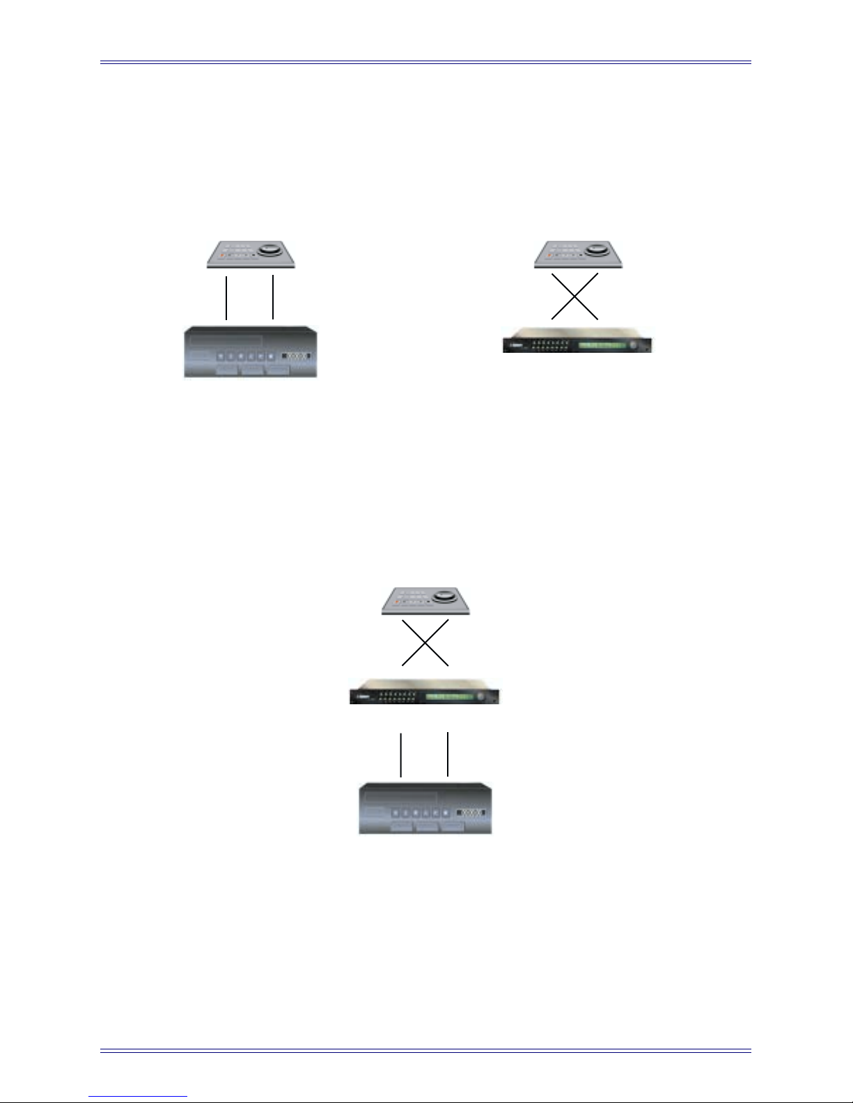
TT007 as Device
Figure A-2 shows a typical virtual machine configuration with the TT007 serving as
random access TC Generator to drive sequencers and/or DAWs; uses reverse Tx/Rx
cable pinout wiring.
Remote Controller only
+Tx/-Tx +Rx/-Rx
+Tx/-Tx +Rx/-Rx
Equivalent
Remote Controller only
+Tx/-Tx +Rx/-Rx
+Tx/-Tx +Rx/-Rx
Configurations
TcG Master
VCR Device only
Figure A-2 TT007 as device
TT007 as Device
TT007 used as Secondary Controller
Figure A-3 shows an expanded control configuration that allows two Controllers simultaneous control of a single Device; uses reverse Tx/Rx cable pinout wiring.
Remote Controller only
+Tx/-Tx +Rx/-Rx
+Tx/-Tx +Rx/-Rx
TT007 as Emulator & Controller
+Tx/-Tx +Rx/-Rx
+Tx/-Tx +Rx/-Rx
VCR Device only
Figure A-3 TT007 as secondary controller
32
Page 33

Euphonix TT007 Operation Manual Appendix
TT007 as Multiple Controller Hub
Figure A-4 shows a configuration that takes advantage of the TT007’s unique ability to
accept and translate commands from multiple controllers to a single master device. Any
one of the four controllers in the network can operate the transport on the tape machine.
Uses reverse Tx/Rx cable pinout wiring.
Remote Controller only
+Tx/-Tx +Rx/-Rx
+Tx/-Tx +Rx/-Rx
TT007 as Emulator & Controller
Tape Machine Device only
For additional system configurations, see Chapter 3: Configurations.
DAW Controller only
+Tx/-Tx +Rx/-Rx
+Tx/-Tx +Rx/-Rx
+Tx/-Tx +Rx/-Rx
+Tx/-Tx +Rx/-Rx
Figure A-4 TT007 as multiple controller hub
Euponix Console Controller only
MIDI
33
Page 34
Euphonix TT007 Operation Manual Appendix
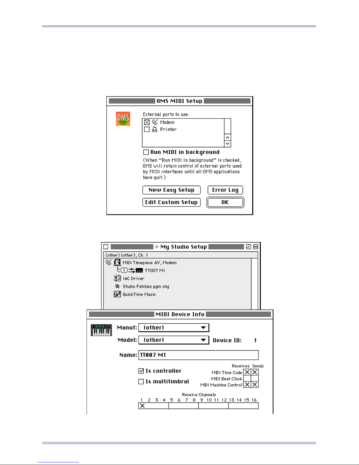
A.3 MIDI Operation with Pro Tools
A.3.1 OMS MIDI Setup
Configure settings according to those set in the following dialogs.
Figure A-5 OMS MIDI Setup
Figure A-6 OMS Studio Setup and MIDI Device Info dialogs
34
Page 35
Euphonix TT007 Operation Manual Appendix
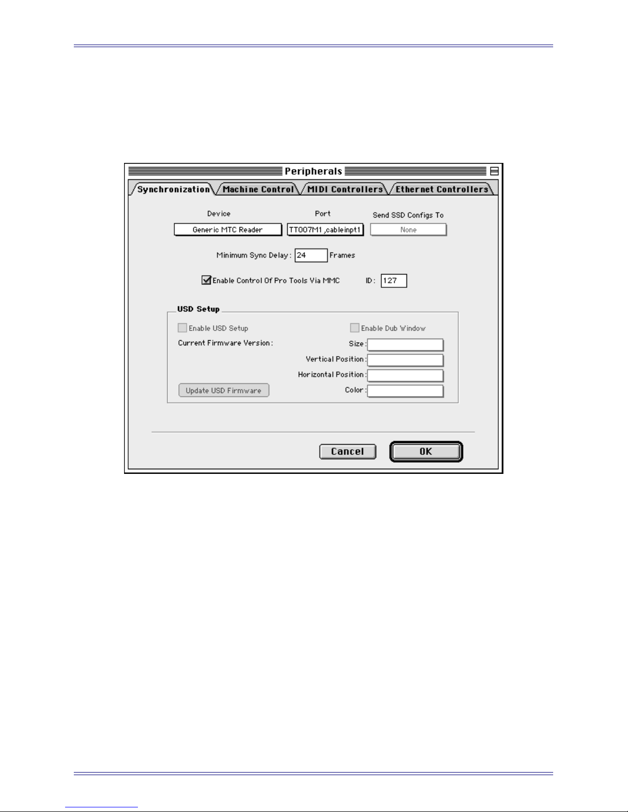
A.3.2 Pro Tools as Master
In the Synchronization tab of the Pro Tools Peripherals dialog (Figure A-7), select the
Enable Control of Pro Tools via MMC checkbox. Configure other settings according
to Figure A-7.
Figure A-7 Synchronization tab in the Pro Tools Peripherals dialog
On the TT007, set the MIDI port to: MTC only and Master.
This setup will not permit track-arming from the console but will allow recording to be
initiated from the console. There is no record tally. For these reasons, this setup is not
recommended. If you need these functions, see Section A.4.2 - ProTools (9-pin Re-
mote) as a Serial Master or Slave.
35
Page 36

Euphonix TT007 Operation Manual Appendix
A.3.3 Pro Tools as Controller
In the Synchronization tab of the Pro Tools Peripherals dialog (Figure A-7), deselect
the Enable Control of Pro Tools via MMC checkbox.
In the MIDI Controllers tab, configure the settings as shown in Figure A-8.
Figure A-8 MIDI Controllers tab in the Pro Tools Peripherals dialog
In the Transport Control, set the Transport menu to Pro Tools (Figure A-9).
Figure A-9 Pro Tools Transport Controls
On the TT007, set the MIDI port to Controller. This setup will not allow track-arming
from the console but will allow recording to be initiated from the console.
36
Page 37

Euphonix TT007 Operation Manual Appendix
A.4 9-Pin Operation with ProTools
A.4.1 OMS Setup
Deselect the Modem port in the OMS MIDI Setup dialog (Figure A-5).
A.4.2 ProTools (9-pin Remote) as a Serial Master or Slave
To control Pro Tools from the TT007, configure Pro Tools as follows:
1. Set the Machine Control tab in the Peripherals dialog as shown in Figure A-10.
Figure A-10 Machine Control tab in the Pro Tools Peripherals dialog
2. Click the clock on the upper-left of the Transport Control so it highlights (as
shown in Figure A-9). This sets Pro Tools Online and relinquishes local control.
3. Select the Remote option from the Transport Control’s Transport menu.
Track-arming (only when Pro Tools is stopped) and record are functional but Quick
Punch must be selected.
Track tallies are turned off while Pro Tools is in record so check the ProTools screen
for track status. The TT007 can fake tallies, but if arming is changed while Pro Tools
is in motion, the console tally states will be out of sync.
37
Page 38

Euphonix TT007 Operation Manual Appendix
On the TT007, set:
• Stop = Stop
• Arming = On or 48 no tallies
Use the Pro Tools remote mode 9-pin cable shown below. A serial control 9-pin cable
or v-LAN configuration will not work
6 7 8
3 4 5
1 2
1 2 3 4 5
6 7 8 9
Mini-8 9-Pin D-Sub
3
4
5
6
8
Figure A-11 Pro Tools Remote Mode 9-pin cable
2
9,1
8
7
3
38
Page 39

Euphonix TT007 Operation Manual Appendix
A.5 Operation with a 3324, 3348, or 3348HR
Master (Word Clock)
1. For System 5, connect the word clock from the SH612 to the 3348.
2. Connect the 3348 to the TT007’s serial port.
3. Set the port to Master.
4. Set the machine type to TC in Play.
T/C from Master will be active.
5. Connect the LTC from the 3348 to the TT007’s TcR.
If the tape was striped to a video reference:
• the machine type can be set to Normal;
• TT007 should be video referenced;
• LTC is not needed.
Master (Video Sync)
1. Connect video sync to the 3348 and the TT007.
2. Connect the 3348 to the TT007’s serial port.
3. Set the port to Master.
4. For System 5, connect the word clock from the 3348 to the SH612.
5. Set the SH612 to Reference Word Clock.
Slave (Word Clock)
1. For System 5, connect the word clock from the SH612 to the 3348.
2. Connect the 3348 to the TT007’s serial port.
3. Set the port to Slave.
4. Set the machine type to 33xx.
39
Page 40

Euphonix TT007 Operation Manual Appendix
Slave (Video Sync)
1. Connect video sync to the 3348 and TT007.
2. Connect the 3348 to the TT007’s serial port.
3. Set the port Slave.
4. Set the machine type to 33xx.
5. For System 5, connect the word clock from the 3348 to the SH612.
6. Set the SH612 to Reference Word Clock.
If record and track arming control is needed when running as a slave, set Re-direct to
the machine’s port.
NOTE: The Sony 3348HR used for testing did not accept Track Arm and Record commands
simultaneously. From the System 5 Main panel, Machines –> Setup –> Track Arm
in Motion should be set to Arm Only.
40
Page 41

Euphonix TT007 Operation Manual Appendix
EUPHONIX INC.
220 PORTAGE AVE.
PAL ALTO, CALIFORNIA
U.S.A.
Date: February 12, 1998 Sheet 1 of 1
Size Document Number REV
A2 TT007 Cables 1
Title
TIME TRANSPORTER - TEST & CONVERTOR CABLES
TT007-2
TxD-
RxD-
TxD+
RxD+
GND
GND
12J27
-RX7
+RX7
-TX7
+TX7
+5V
0V
S4
REMOTE
POWER (+5V)
(+5V)
TT007-2 S4
1234567
8
RJ45 Socket
0V
5
9
4
8
3
7
2
6
1
9 WAY D FEMALE
TT007-2
S1, S2, S3
-RX
+RX
+TX
-TX
0V
5
9
4
8
3
7
2
6
1
9 WAY D FEMALE
-RX
+RX
+TX
-TX
0V
5
9
4
8
3
7
2
6
1
9 WAY D MALE
TT007-2 Controller to Controller
Interface Pinout / S1, S2, S3
-RX
+RX
+TX
-TX
TT007
|
|
Controller
Diagnostic Port i/f
1234567
8
RJ45 Socket
This cable allows for connection to a
5
9
4
8
3
7
2
6
1
9 WAY D FEMALE
TxD-
RxD-
TxD+
RxD+
GND
GND
(+5V)
(+5V)
PC/Mac via RS232, when enabled
TT007-2 S4
NET (GP132) i/f
This cable connects to the GP132
Track Arming system, when enabled
TxD-
RxD-
TxD+
RxD+
GND
GND
(+5V)
(+5V)
1234567
8
RJ45 Socket
1234567
8
RJ45 Socket
GND
GND
(+5V)
(+5V)
TxRx1-
TxRx1+
TxRx2-
TxRx2+
TT007-2 S4 GP132 NIN, NOUT
5 9 4 8 3 7 2 6 1
9 WAY D MALE
TT007-2
Self Testers
RJ45 Socket
This a simple loop back dongle to
use with built in self diagnostics.
TxD-
RxD-
TxD+
RxD+
GND
GND
(+5V)
(+5V)
TT007-2
S4S1, S2, S3
1234567
8
A.6 Cable Pinouts
Figure A-12 Cable pinout diagrams
41
Page 42

 Loading...