

Page 1
6
RR1
1
-- L
SSLL11556
L
AARRGGEE
F
OORRMMAATT
F
S
S
TTUUDDIIOO
L
L
C
OONNSSOOLLEE
C
IINNK
K
I
I
NNTTEERRFFAACCE
E
P
RREELLIIMMIINNAARRYY
P
Revision 9 Compatible with v0.9a Software - Friday, 18 January 2002
O
SL156
I
M
M
AANNUUAAL
L
TRAC K W IND PAUSE PLAY
LAMPS SW MIDI TC
<< >> STOP PLAY
DIAG
ALT FUN C
RECORD
MODE
STD
R1
AUTO
R1
AUTO
Page 2

Oxford Project
SL156 – MANUAL
CONTENTS
CONTENTS ------------- --------------------------- -------------------------------------------------------------------------------------------------- ---1
ECTION 1 FEATURE LIST ------------------------ ------------------------------------------------------------------------------------------------2
S
T
RANSPORT CONTROL FROM
48 T
RACK RECORD READY ARMING AND TALLIES FROM SSL --- ---------------------------- ----------------------------------------------2
D
IRECT CUE CONTROL FROM SSL AUTOMATION SYSTEM - INSTANT LOCATES ----------- ----------------------------------------------2
D
IRECT CUE CONTROL FROM NEVE FLYING FADERS - INSTANT LOCATES ------------------------- -------------------------------------2
S
ELECT R1 OR STANDARD MACHINE WITH NO PATHCHING----------------------------------------------------------------------------------2
S
S
2 F
ECTION
ECTION 3 TRANSPORT REMOTE FUNCTIONS---------------------------------- --------------------------------------------------------------4
RONT PANEL -----------------------------------------------------------------------------------------------------------------------------3
SL156 F
SL156 R
EAR PANEL---------------------------------------------------------------------------------------------------------------------------- ---3
RONT
& R
Normal Key functi ons: -----------------------------------------------------------------------------------------------------------------------4
Additional Key functions:--------------------------------------------------------------------------------------------------------------------4
Additional Lamp functions: -----------------------------------------------------------------------------------------------------------------4
SECTION 4 FRONT PANEL OPTIONS ------------------------- -----------------------------------------------------------------------------------5
ORMAL OPERATION MODE ----------------------------------------------------------------------------------------------------------------------5
N
F
UNCTION MODE-------------- ---------------------------------------------------------------------------------------------------------------------6
A
LTERNATIVE MODE ------------------------------------------------------------------------------------------------------------------------------7
S
ECTION 5 SSL G SERIES COMPUTER SETUP-------------------------------------------------------------------------------------------------8
SSL P
ROGRAM DISK SETUP ----------------------------------------------------------------------------------------------------------------------8
SSL H
ARDWARE SE TUP----------------------------------------------- -------------------------------------------------------------------------- 10
Console Remote S29 - 25 way D Ty pe Male.------------------------------------------------------------------------------------------- 10
D1 DL41 TRACKS 1-24, D2 DL42 TRACKS 25-48 - 50 way D Type Female.-------------------------------------------------- 10
P LINK s88 - 25 way D Type Male.---------- -- ----------------------------------------- -- --------------------------- --- ----------------- 10
CONSOLE TC - XLR Ma le, R1 TC - XLR Female. ----------------------------------------------------------------------------------- 10
R1 LINK - 9 way D Type Fema le.-------------------------------------------------------------------------------------------------------- 10
S
ECTION 6 NEVE FLYING FADERS COMPUTER SETUP ------------------ ----------------------------------------------------------------- 11
N
EVE PROGRAM DISK SETUP------------------------------------------------------------------------------------------------------------------- 11
SSL H
ARDWARE SE TUP----------------------------------------------- -------------------------------------------------------------------------- 11
Console Remote S29 - 25 way D Ty pe Male.------------------------------------------------------------------------------------------- 11
N LINK - 9 way D Type Male. ------------------------------------------------------------------------------------------------------------ 11
N LINK Cable --------------------------------------------------------------------------------------------------------------------- 11
CONSOLE TC - XLR Ma le, R1 TC - XLR Female. ----------------------------------------------------------------------------------- 11
R1 LINK - 9 way D Type Fema le.-------------------------------------------------------------------------------------------------------- 11
S
ECTION 9 CONNECTOR PINOUTS ------------------------------------------------------------------------------------------------------------ 12
XT REMOTE S29 - 25 WAY D TYPE FEMALE.------------------------------------------------------------------------------------------ ---- 12
E
C
ONSOLE REMOTE S29 - 25 WAY D TYPE MALE.------------------ -------------- ---------------------------------------------------------- 12
P LINK
S88 - 25 WAY D TYPE FEMALE. --------------- --------------------------------------------------------------------------------- ---- 12
D1 & D2 - 50
WAY
CONSOLE TC - XLR M
E
XT TC - XLR FEMALE.------------------------------------------------- ---------------------------------------------------------------------- 13
R1 TC - XLR F
R1 LINK - 9
N LINK - 9
M
IDI IN
M
IDI THRU – 5 WAY DIN FEMALE.---------------- ------------- ------------------------------------------------------------------------------- 13
M
IDI OUT – 5 WAY DIN FEMALE.--------------------- ------------------------------------------------------- --------------------------------- 13
ECTION 10 SPEC SHEET---------------------------------------- ------------------------------------------------------------------------------- 14
S
NS & OUTS:-------------------------------------------------------------------------------------------------------------------------------------- 14
I
M
ECHANICAL:------------------------ ------------------------------------------------------------------------------------------------------------ 14
OWER:-------------------------------------------------------------------------------------------------------------------------------------------- 14
P
PPENDIX A R1 TO CONSOLE CHART---------- --------------------------- ----------------------------------------------------------------- 15
A
HIS CHART IS TO HELP PICK THE CORRECT CONFIGURATION FOR AN R1 + SL156 ---------------------------------------------------- 15
T
EMALE. -------------------------------------------------------------------------------------------------------------- ---------- 13
WAY D TYPE FEMALE.------------------------ --------------------------- ------------------------------------------------------ 13
WAY D TYPE FEMALE.----------------------------------------------------------------------------------------------------------- 13
– 5
WAY DIN FEMALE
SSL
NEVE T
OR
EAR PANELS
D T
YPE FEMALE
ALE. ------------------------------------------------------------------------------------------------------ ---------- 13
------------- --------------------------- -------------------------------------------------------------------3
.---------------- -------------- -------------------------------------------------------------------------- 12
RANSPORTS
-------------- --------------------------- ----------------------------------------2
.---------------------------------------------------------------------------------------------------------------- 13
EUPHONIX O P – SL156 - MANUAL DJP 18/01/02 16:36
Page 1
Page 3

Oxford Project
SL156 – MANUAL
SECTION 1 FEATURE LIST
TRANSPORT CONTROL FROM
SSL
A 25 way connector takes transport keys and lamp tallies to and from the
user. This connector is the
SERIES COMPUTER.
The la m p ta l ly driv ers are 24 V.
RACK RECORD READY ARMING AND TALLIES FROM
48 T
Two 96 way DL connectors match to the
desks, connecting the Record Ready signals. These two connectors take 24
tallies each to and from the
The Lamp tally drivers are 24V.
IRECT CUE CONTROL FROM SSL AUTOMATION SYSTEM - INSTANT LOCATES
D
A 25 way connector links to the
support for the long defunct
With this port enabled the
SSL G SERIES COMPUTER
offsets, as well as receiving position and lock information. Unfortunately the
"TACH"
&
"DIRECTION"
NEVE
OR
SSL standard that also provides
(SSL desks are fitted with 36V bulbs, for “longer life”)
.
R1
(SSL desks use opto-isolators to read the tally signals)
SSL
Z8 machine control package.
SSL
TRANSPORTS
"TACH"
SSL
SSL DL patch under the 4000, 6000, 8000 & G series
parallel card, that (in the past) provided synchroniser
is able to issue Locate / Cue commands and set
&
"DIRECTION"
R1, for the console
for the SSL G
READY Key and Lamp
still requires
SSL
The connection is via an 8 bit bi-directional parallel port (with handshaking) running at 5V. This
limits dramatically the safe cable length of this connection.
The
Timeline
and
Motionworks
synchroniser support for the
companies have used this connection to provide
SSL G SERIES COMPUTER
.
LYNX
and other
IRECT CUE CONTROL FROM NEVE FLYING FADERS - INSTANT LOCATES
D
A 9 way RS232 port l i nk s to the
2600 synchroniser Serial Interface module.
This port allows the
NEVE FLYING FADERS COMPUTER to be able to issue Locate / Cue, Cycle and some
NEVE FLYING FADERS COMPUTER which "simulates" an Adams-Smith
direct transport commands.
Motionworks company has used this connection to provide LYNX and ot her s ync hr on iser
The
support for the
ELECT R1 OR STANDARD MACHINE WITH NO PATH CHING
S
NEVE FLYING FADERS COMPUTER.
A 25 way connector also provides for a standard machin e (already interfaced to the console) to
be swapped in place of the
R1.
This allows for going back to a "2 inch" session with no rewiring. This feature provides instant
swapping between the
R1 and any parallel controlled tape machine.
The connector is "hard" switched to the T ransport Control connector via rel a ys.
The choice between ma chines can be cont rolle d directly from t he
EUPHONIX O P – SL156 - MANUAL DJP 18/01/02 16:36
SSL G SERIES COMPUTER.
Page 2
Page 4
Oxford Project
SL156 – MANUAL
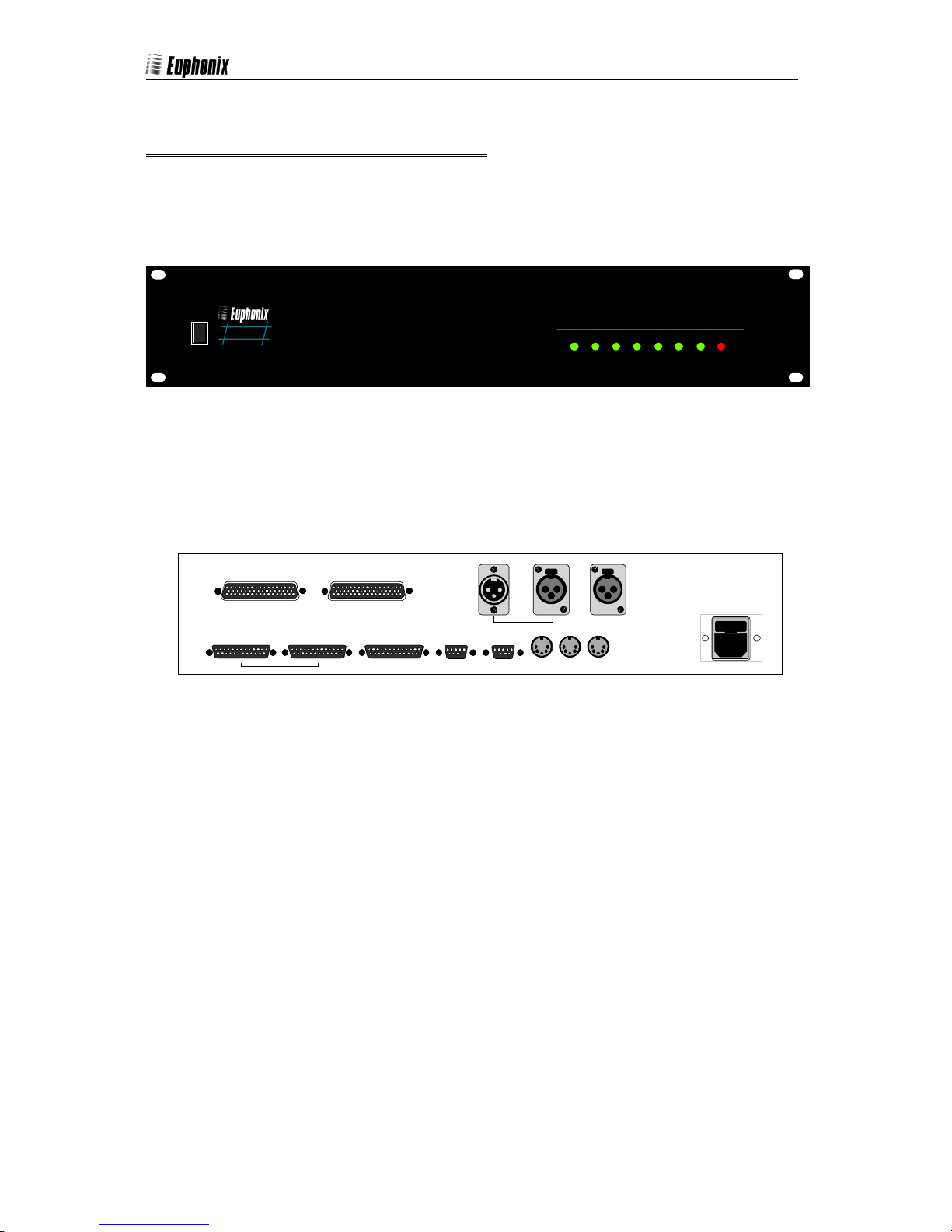
SECTION 2 FRONT & REAR PANELS
SL156 FRONT PANEL
This is a very simple panel that allows for "activity" indicators and simple transport control
(mainly for test purposes).
O
SL156
I
SL156 R
EAR PANEL
Providing access to all connectors.
DL41
D1
EXT REMOTE s
TRACKS 1-24
29
CONSOLE REMOTE s
D2
DL42
TRACKS 25-48
29
P LINK s
TRAC K W IND PAUSE PL AY
LAMPS SW MIDI TC
<< >> ST OP PL AY
CONSOLE TC EXT TC R1 TC
88
R1 LINK
N LINK
IN OUTTHRU
MIDI
DIAG
ALT FUNC
RECORD
MODE
R1
R1
STD
AUTO
AUTO
AC INPU T
100V TO 2 60V
50 TO 60 HZ
EUPHONIX O P – SL156 - MANUAL DJP 18/01/02 16:36
Page 3
Page 5
Oxford Project
SL156 – MANUAL
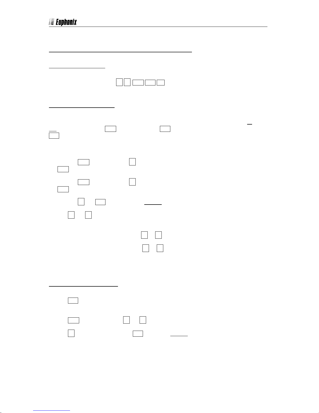
SECTION 3 TRANSPORT REMOTE FUNCTIONS
NORMAL KEY FUNCTIONS:
The transport key and
LAMPS
<<
>>
STOP PLAY REC
perform their normal functions.
DDITIONAL KEY FUNCTIONS:
A
The SL156 provides an exact copy of mechanical transport acti ons i.e. all keys react to on an d
actions e.g. with the STOP key held down the PLAY key will put the R1 into play, as soon as the
off
PLAY key is released the R1 will go back to stop.
There are some additional combinations from the remote keys that provide some additional
functions, without any compromise to normal use and reliab ility.
Pressing STOP and then holding >> down puts the R1 into half speed shuttle forward. If
is then released first, the
STOP
Pressing
is then released first, the R1 will stay in this mode.
STOP
Pressing
The
<<
the front panel.
and then holding
STOP
and
<<
and
PLAY
keys pro vides tw o w a ys of fas t fo rward, t he s e t wo modes ar e s e t fr om via
>>
(see Alternative Mode)
puts th e R1 into reverse play.
will stay in this mode.
R1
down puts the R1 into half speed shuttle reverse. If
<<
1. In normal
(default)
mode pressing << or
2. In the alternative mode pressing << or
puts the R1 into fast forward / rew ind.
>>
the first time puts the
>>
forward wind. The second time 16 x play speed.
A
DDITIONAL LAMP FUNCTIONS:
The
PLAY LAMP
changed v ia the front panel
The
The << LAMP flashes with a solid PLAY to indicate reverse play.
EUPHONIX O P – SL156 - MANUAL DJP 18/01/02 16:36
STOP LAMP
flashes if the R1 is in play but no timecode is being read – this function can be
flashes with
(see below)
<<
or
.
to indicate slow wind, shuttle or jog.
>>
into 8 x play speed
R1
Page 4
Page 6

A
A
Oxford Project
SL156 – MANUAL
SECTION 4 FRONT PANEL OPTIONS
NORMAL OPERATION MODE
The transport key and
LEDS
<< >>
their normal functions.
The
The
The
The
The
PLAY LED
STOP LED
FUNC
ALT
R1
flas h es if the
flash es with
key selects the
key selects the
R1
<<
F
UNCTION MODE
A
LTERNATIVE MODE
key selects between the R1 and EXTERNAL machine. If the R1 is selected the
flashes to indicate no communication.
The
AUTO LED
flashes to indicate no communication with the automation system.
TRACK WIND PAUS E PLAY
STOP
PLAY
perfor m
LAMPS SWMIDITC
<< >> STOP PLAY
is in play but no timecode is being.
or
to indicate slow wind, shuttle or jog.
>>
(see below)
(see below)
.
.
MODE
RECORD
DIAG
FUNC
ALT
R1
R1
LED
STD
UTO
UTO
EUPHONIX O P – SL156 - MANUAL DJP 18/01/02 16:36
Page 5
Page 7

UNCTION MODE
A
AUTO
A
AUTO
A
AUTO
A
AUTO
A
AUTO
F
Oxford Project
SL156 – MANUAL
The
FUNC
tions
By pressing the
FUNC key the row of bold blue functions are
enabled.
this key puts the unit into lamp test mode – the unit
LAMPS
cycles through all 24V lamps (Record Ready and Transport)
and off. This is a good way of ratifying that cables to
on
the console are functioning.
this key puts the unit into switch test mode – the unit
SW
waits for a switch closure and toggles the corresponding
lamp. This test is only useful after the lamp test has been
conducted successfully.
this key puts the unit into MIDI test mode - the unit
MIDI
(not available)
transmits a MIDI message stream and lights the SL156
front panel
mode allows the unit’s MIDI IN/OUT to be tested.
MIDI
STOP LED
if the MIDI message is received.
TRACK WIND PAU SE PLAY
LAMPS SWMIDI TC
<< >> STOP PLAY
TRACK WIND PAU SE PLAY
LAMPS SWMIDI TC
<< >> STOP PLAY
The
LAMPS
TRACK WIND PAU SE PLAY
LAMPS SWMIDI TC
<< >> STOP PLAY
The SW key
TRACK WIND PAU SE PLAY
LAMPS SWMIDI TC
<< >> STOP PLAY
The
MIDI
DIAG
ALT
The
DIAG
ALT
key
DIAG
ALT
DIAG
ALT
key
RECORD
FUNC
RECORD
FUNC
RECORD
FUNC
RECORD
FUNC
MODE
R1
R1
FUNC
MODE
R1
R1
MODE
R1
R1
MODE
R1
R1
STD
UTO
key
STD
UTO
STD
UTO
STD
UTO
this key puts the unit into timecode mode - the unit
TC
reads timecode an d l ights th e
if code is found on the
speed timecode from
00:00:00.00
SL156
XLR. The unit sends out play
R1 TC
as soon as this mode is enabled.
front pa n el
on the
TC
CONSOLE TC
mode allows the unit’s
PLAY LED
XLR
TRACK WIND PAU SE PLAY
LAMPS SWMIDI TC
<< >> STOP PLAY
DIAG
ALT
The TC key
RECORD
FUNC
timecode functions to be tested independently.
this key enables the
DIAG
function to cycle all 24V
LAMPS
together – this is rather an
LAMPS
aggressive way of testing.
key function...
R1
AUTO
(not available)
this key puts the unit into
P-LINK S88 PORT
test mode - the unit continually swaps the
direction of the data and handshaking lines to test that each bit can read and wri te. This
test requires a special 25 way D cable and should not be used when the P-LINK is in use
with an SSL computer.
Cable details - 25 way D Male, cross-connected as follows:
1 ----- 5
-----
14
2 ----- 8
-----
15
7
13
MODE
STD
R1
R1
UTO
EUPHONIX O P – SL156 - MANUAL DJP 18/01/02 16:36
Page 6
Page 8

A
AUTO
A
AUTO
A
AUTO
A
AUTO
A
AUTO
Oxford Project
LTERNATIVE MODE
A
SL156 – MANUAL
By pressing (and holding down) the
ALT key the top row of blue
settings are displayed. These settings maybe altered only,
while the
key is held down.
ALT
setting - when the
TRACK
is ON, the SL156 controls
LED
track arming using the “3324” method (as used by the R1).
is
When the
LED
, the SL156 control s t r ac k ar m in g u s in g
OFF
the “Radar” method.
setting- when the
WIND
ballistics with
<<
and
is ON, the SL156 uses the R1
LED
When the
>>.
LED
is
OFF
, the SL156
uses three set wind speeds. (see SECTION 4 TRANSPORT REMOTE
UNCTIONS
F
PAUSE
issued in stop, when the
)
setting - when the
LED
LED
is ON a
is
OFF
P
AUSE
a
S
TOP
command is
(P2)
command is
(P2)
issued in stop.
setting - when the
PLAY
is ON, the
LED
lamp will flash
PLAY
when there’s no timecode present in play, when the
the
OFF
SL156 front panel
lamp stays solid always in play. Note: the
PLAY
PLAY LED
always flashes when there’s no
LED
timecode present in play.
is
The
ALT
TRACK WIND PAU SE PLAY
LAMPS SWMIDI TC
<< >> STOP PLAY
TRACK WIND PAU SE PLAY
LAMPS SWMIDI TC
<< >> STOP PLAY
The TRACK key
TRACK WIND PAU SE PLAY
LAMPS SWMIDI TC
<< >> STOP PLAY
The WIND key
TRACK WIND PAU SE PLAY
LAMPS SWMIDI TC
<< >> STOP PLAY
The PAUSE key
TRACK WIND PAU SE PLAY
LAMPS SWMIDI TC
<< >> STOP PLAY
The PLAY key
settings
RECORD
DIAG
FUNC
ALT
The
ALT
RECORD
DIAG
FUNC
ALT
RECORD
DIAG
FUNC
ALT
RECORD
DIAG
FUNC
ALT
RECORD
DIAG
FUNC
ALT
key
MODE
STD
R1
R1
UTO
MODE
STD
R1
R1
UTO
MODE
STD
R1
R1
UTO
MODE
STD
R1
R1
UTO
MODE
STD
R1
R1
UTO
RECORD
MODE
STD
when the
setting...
(no function defined yet)
setting – follows the
setti n g - w h en t h e
LED
is
OFF
the
state at present.
TRACK
is ON, the
LED
NEVE FLYING FADERS COMPUTER
SSL G SERIES COMPUTER
protocol and
EUPHONIX O P – SL156 - MANUAL DJP 18/01/02 16:36
protocol and
N LINK
are enabled,
P LINK
are enabled.
Page 7
Page 9

Oxford Project
SL156 – MANUAL
SECTION 5
SSL
G SERIES COMPUTER SETUP
SSL PROGRAM DISK SETUP
To run the Studio Link 156 with an
SSL G SERIES COMPUTER, certain parameters need to be set up on
the G computer.
It is essential to make a copy of the current (in use) program disk, so that all previous options
are backed up.
On the G s e r i es keybo a rd :
Boot program (
Setup Program Disk options
Password =
[SETUP] [EXECUTE]
= System Menu ----------------------------
#
[END] [END] [END]
Reboot program
BEGIN [EXECUTE]
)
BEGIN
SSL [EXECUTE] 4100
Synchroniser Controller | 1
Master Transport Selector | Yes
Setup SYNC
[SETUP] [EXECUTE]
M = Maintenance Menu
[SYNC]
I = Synchroniser Interface ------------------
[END]
Z8 Interface no
|2
[END]
[END]
[SETUP]
[SYNC]
S = Misc. sync opti ons -------- ----------------
[END] [END] [END]
EUPHONIX O P – SL156 - MANUAL DJP 18/01/02 16:36
= Machine set-up. --------------------
= Synchroniser set-up. ---------------
A|R1 |16
B | External | 1?
C| |
D| |
E| |
Maximum number of masters | 2
Offsets can be read from |
synchronizer | Yes
Single machine mode | No
Timecode generation | No
Time to wait for synchroniser | 5.00
Playtopark |No
Play to park roll time | 0.00
Film machine drop-out option | No
Page 8
Page 10

p
|
Oxford Project
Setup TAPE MACHINE
[SETUP] [EXECUTE]
SL156 – MANUAL
M = Maintenanc e M enu
T = Tape Machines Details
select a machine " spare" 16 ??
[END] [END] [END]
Setup Timecode
[SETUP] [EXECUTE] More?
Y = Yes
[END]
[END] [END] [END]
S = This Session ------------------------------
= Sync options -----------------------
[SYNC]
[EXECUTE] ----
Autolocate type | 3
Autolocate decision interval | 0.02
Forward direction sense (L/H) | LOW
Multi play speeds (Y/N/S)? | NO
Pulses/second at std. speed | FRAME
Target window | 0.00
Drop-out command type | 1
Drop-in command type | 1
Time for machine to startup | 1.00
Time before sure tape stopped | 0.05
Pessimism factor (fwd) | 10
Pessimism factor (bkwd) | 10
Short locate time (secs) | 1
Max stopping distance | 2
Frames to stop from play | 0.10
Frame jog card fitted | NO
Timecode frames per second | -Using dropframe | -Using VITC? | YES
Display time(T) or feet(F) | -Display frames | -Runup (preroll) time | -...
Synchroniser in use | YES
Resolve master machine | NO
Slow lock mode | NO
Grou
locates
NO
Some of these parameters will be different, depending on the particular installation. Some
others maybe different because of engineer preference, these are indicated with “
“ in the
--
appropriate menus.
Not all of the tape machine parameters are fully understood
(by SSL or us)
and may require
additional modification to get the best performance from the system.
- to select the
AM
enabling the
- to select
BM
the
EXT
the
EXT
EUPHONIX O P – SL156 - MANUAL DJP 18/01/02 16:36
R1
EXT
machine. Then type
machine normally.
from the
R1
. Then type
from the
type AM this selects the “A” machine as the master,
SSL
[SYNC] O N
SSL
[SYNC] OFF
to allow the
SSL G SERIES COMPUTER
type BM this selects the “B” machine as the mas ter, enabling
to allow the
SSL G SERIES COMPUTER
to use the
to be able to locate
Z8
port.
Page 9
Page 11

ARDWARE SETUP
SSL H
Oxford Project
SL156 – MANUAL
ONSOLE REMOTE S29 - 25
C
WAY
A 25 way D connector takes Transport Key and Lamp tallies to and from the
user, this connects to the Console Remote connector on the
series desks. This connector is the
YPE MALE
D T
.
SSL stand ard that also provides
R1 for the console
SSL patch under the 4000, 6000, G
"TACH"
&
"DIRECTION"
for the
SSL G SERIES COMPUTER. The Lamp tally drivers are 24V.
D1
DL41 TRACKS 1-24, D2 DL42 TRACKS 25-48 -
50 WAY D TYPE FEMALE.
The two (2) 50 way D connectors provide the 48 Record Ready signals these connect to two 96
way DL connectors (DL41 & DL42) on the
SSL DL patch under the 4000, 6000, 8000 & G series
desks. Connecting to the Record Ready signals.
These two connectors take 24
READY Key and Lamp tallies each to and from the R1.
The Lamp tally drivers are 24V.
S
25 WAY D TYPE MALE.
P LINK
88 -
This is connected to the S88 connector, a 26 way ribbon on an optional card (
Z8
COMMUNICATIONS CARD) in the SSL G SERIES COMPUTER.
With this port enabled, the
SSL G SERIES COMPUTER is able to issue Locate / Cue commands, as well
as receiving position and lock information. This is an 8 bit bi-directional parallel port (with
handshaking) running at 5V.
If this connection is made and the software is set-up the AUTO LED on the
SL156
will go solid.
Flashing indicates no (or intermittent) connection. Note that during s ome operations the SSL
stops “talking” on this port so the odd flash maybe seen.
CONSOLE TC -
The timecode out of the
XLR MALE, R1 TC - XLR FEMALE.
is connected to the R1 TC female XLR. The male XLR (CONSOLE
R1
TC) goes to the SSL SMPTE READER via the patch.
If the R1 is in play, the PLAY
R1 LINK -
This is connected to the
9 WAY D TYPE FEMALE.
R1 Studio Hub
LED
on the
(CONTROL 9 WAY D TYPE FEMALE). This controls
R1.
the
will go soli d. Flashing indicates no timecode.
SL156
SSL 4000, 6000, G Series
If the R1 is connected and communicating
the R1 PLAY
Flashing indicates no communication.
LED on the SL156 will go solid.
DL41
S8
MULTITRACK
Patchbay
1-24
TRACKS
Console Remot e
Ext Remote N Link
S29
25-48
TRACKS
DL42
Parallel Link
S88
EUPHONIX R1
CONSOLE TC Ext TC R1 TC
R1 Link
S1
S2
E/G Se r i es
Computer
THRU
IN
IN OUT
THRU
DAW,
Sequencer
OUT
MIDI
EUPHONIX O P – SL156 - MANUAL DJP 18/01/02 16:36
Page 10
Page 12

Oxford Project
SL156 – MANUAL
SECTION 6
NEVE
FLYING FADERS COMPUTER SETUP
NEVE PROGRAM DISK SETUP
To run the Studio Link 156 with a
enabl ed an d t h e
SL156 connected to the NEVE FLYING FADERS COMPUTER.
NEVE FLYING FADERS COMPUTER, the transport control needs to be
That’s about all you have to do.
SSL HARDWARE SETUP
ONSOLE REMOTE S29 - 25
C
WAY
A 25 way D connector takes Transport Key and Lamp tallies to and from the
user, this connects to the Console Remote connector on the
WAY
N LINK -
9
This is connected to the
This port enables the
YPE MALE
D T
NEVE FLYING FADERS COMPUTER
NEVE FLYING FADERS COMPUTER
.
D T
YPE MALE
.
for the console
R1
NEVE FLYING FADERS COMPUTER
.
.
to be able to issue Locate / Cue commands, as
well as receivi ng position and lock information. This is an RS232 serial port runni ng at 9600
BAUD.
If this connection is made and the software is set-up the AUTO LED on the
SL156
should go
solid. Fl as hi ng indicates no (or intermittent) connection. The odd flash is not unusual.
N LINK Cable
SL156 NEVE FLYING FADERS COMPUTER
GND 11--
not used
RX- 22--
not used 77-- not used
not used
TX- 88--
not used
not used
not used
66-- not used
33--
44
99-- not used
55
not used
not used
--
not used
-- GND
SL156 N Link to NEVE FLYING FADERS COMPUTER cable is: pin 1 to 5, pin 2 to 3, pin 8 to 2.
CONSOLE TC -
XLR MALE
The timecode out of the
TC) goes to the
NEVE FLYING FADERS COMPUTER.
If the R1 is in play, the PLAY
R1 LINK -
9 WAY D TYPE FEMALE.
This is connected to the
, R1 TC -
R1 is connected to the
LED on the SL156 will go solid. Flashing indicates no timecode.
R1 Studio Hub (CONTROL 9 WAY D TYPE FEMALE). This controls the R1.
If the R1 is connected and communicating the R1 PLAY
XLR FEMALE
.
TC female XLR. The male XLR (CONSOLE
R1
LED
on the
will go solid. Flashing
SL156
indicat es no co mm uni cation.
EUPHONIX O P – SL156 - MANUAL DJP 18/01/02 16:36
Page 11
Page 13

Oxford Project
SL156 – MANUAL
SECTION 9 CONNECTOR PINOUTS
EXT REMOTE S29 - 25
1 -- not connected
14 --
2 -- LAMP COMMON
15 -- SWITCH COMMON
3 -- SWITCH RWD
16 -- LAMP RWD
4 -- SWITCH FWD
17 -- LAMP FWD
5 -- SWITCH STOP
18
6 -- SWITCH PLAY
19
7 --
20 -- not connected
8 -- SWITCH RECORD
21 -- LAMP RECORD
9 -- TACH 1
22 -- TACH 2
10 -- DIR 1
23 -- DIR 2
11 --
24 -- not connected
12 --
25 -- not connected
13
not connected
-- LAMP STOP
-- LAMP PLAY
not connected
not connected
not connected
--
not connected
WAY
YPE FEMALE
D T
.
P LINK
S
25 WAY D TYPE FEMALE.
88 -
1
-- DATA 0
14 -- DATA 1
2 -- DATA 2
15 -- DATA 3
3 -- DATA 4
16 -- DATA 5
4 -- DATA 6
17 -- DATA 7
5 -- SSL OUT
18 --
not connected
6 -- not connected
19 --
not connected
7 -- SSL IN
--
20
not connected
8 -- SSL INT
--
21
not connected
9 -- not connected
22 -- not connected
10 --
not connected
23 -- not connected
11 -- 0V
24 -- 0V
12 --
not connected
25 -- not connected
13 -- SSL RST
CONSOLE REMOTE S29 - 25 WAY D TYPE MALE.
1 -- not connected
14 -- not connected
2 -- LAMP COMMON
15 -- SWITCH COMMON
3 -- SWITCH RWD
16 -- LAMP RWD
4 -- SWITCH FWD
17 -- LAMP FWD
5 -- SWITCH STOP
18 -- LAMP STOP
6 -- SWITCH PLAY
19 -- LAMP PLAY
--
7
20 -- not connected
8
21 -- LAMP RECORD
9 -- TACH 1
22 -- TACH 2
10 -- DIR 1
23 -- DIR 2
11 --
24 --
12 -- not connected
25 --
13 -- not connected
not connected
-- SWITCH RECORD
not connected
not connected
not connected
D1 & D2 - 50 WAY D TYPE FEMALE.
134--
18 --
235--
19 --
336--
20 --
437--
21 --
538
22 --
639
23 --
740--
24 --
841--
25 --
942--
26 --
10 43 --
27 --
11 44 --
28 --
12 45 --
29 --
13 46 --
30
14 47 --
31
15 48 --
32 --
16 49 --
33 --
17 50 --
--
--
--
--
EUPHONIX O P – SL156 - MANUAL DJP 18/01/02 16:36
Page 12
Page 14

Oxford Project
SL156 – MANUAL
CONSOLE TC - XLR MALE.
1 -- GND
2 -- TC+
3
-- TC-
EXT TC - XLR FEMALE.
1 -- GND
2 -- TC+
3 -- TC-
R1 TC -
R1 LINK -
XLR FEMALE.
1 -- GND
2 -- TC+
3 -- TC-
9 WAY D TYPE FEMALE.
1 -- GND
6 -- GND
2
3
4 -- GND
5 --
-- RX-
7 -- RX+
-- TX+
8 -- TX-
9 -- GND
not connected
N LINK - 9 WAY D TYPE FEMALE.
1 -- GND
6 -- GND
2
3
4 -- GND
5 --
-- RX-
7 -- RX+
-- TX+
8 -- TX-
9 -- GND
not connected
MIDI IN – 5 WAY DIN FEMALE.
1 -2 -- not connected
3 -4 -- RX+
5 -- RX-
not connected
not connected
MIDI THRU – 5 WAY DIN FEMALE.
MIDI OUT –
1 -- not connected
2
3 -4 -- TX+
5 -- TX-
-- GND
not connected
5 WAY DIN FEMALE.
1 -- not connected
2 -- GND
3 -4 -- TX+
5 -- TX-
not connected
EUPHONIX O P – SL156 - MANUAL DJP 18/01/02 16:36
Page 13
Page 15

Oxford Project
SL156 – MANUAL
SECTION 10 SPEC SHEET
INS & OUTS:
2 independent serial
RS422 ports
ECHANICAL:
M
OWER:
P
1 independent M
IDI IN OUT
and
THRU
port
48 track (Record Ready) control and tally lines
Timecode
Timecode
Timecode
(XLR) from R1
IN
(XLR) from External Tape Machine
IN
(XLR ) variable gain
OUT
Parallel Tape Remote - to Console
Parallel Tape Remote - External Tape Machine
8 bit parallel control port
19" 2U rack
Auto ranging AC voltage input: 100-260v
Approx. 30watts
EUPHONIX O P – SL156 - MANUAL DJP 18/01/02 16:36
Page 14
Page 16

Oxford Project
SL156 – MANUAL
APPENDIX A R1 TO CONSOLE CHART
THIS CHART IS TO HELP PICK THE CORRECT CONFIGURATION FOR AN R1 + SL156
This list is based on preliminary data so far…
Make Model Transports Record Ready Comms TC SL156?
4000 Yes 25D Yes (48+) Parallel XLR
SSL
5000 ? ? ?
6000 Yes 25D Yes (48+) Parallel XLR
G Yes 25D Yes (48+) Parallel XLR Yes
9000/J Yes (48) P2
V Yes 25D No ? XLR
Neve
inc Flying Faders
Capricorn Yes 25D Yes (48) AS XLR
Yes 25D No AS XLR
Yes
Yes
Yes
Yes
Yes
Oxford R3 No uses RS232 Yes (48) Yes XLR
Sony
Automation ? ? ? XLR
GML
Headquarters
220 Portage Avenue
Palo Alto CA 94306
Tel +1 650 855 0400
Fax +1 650 855 0410
Yes
EUPHONIX O P – SL156 - MANUAL DJP 18/01/02 16:36
Page 15
 Loading...