

Page 1
PILOT COMPUTER
OS DRIVE
SCSI
RESET
Pilot Computer Manual
Version 2.00
Part# 840-0 6265-02 rev B
Publish date: August 1999
Euphonix Inc. 220 Portage Avenue Palo Alto , CA 94306
Tel: (650)855-0400 Fax: (650) 855-0410 Web Page: www.euphonix.com
PC
252
In the interest of continued product development, Euphonix reserves the right to make improvements in this
manual and the product it describe s at any time, without notice or obligation.
©1999 Euphonix Inc. All rights reserved worldwide. No part of this publication may be reproduced,
transmitted, transcribed, stored in a retrieval system, or translated into any language in any form by any
©1999 Euphonix, Inc. Page 1 Pilot Computer Manual
R-1, Audio Deck, Studio Hub are trademarks of Euphonix Inc.
means without written permission of Euphonix Inc.
Page 2

This page intentionally left blank
©1999 Euphonix, Inc. Page 2 Pilot Computer Manual
Page 3

TABLE OF CONTENTS
TABLE OF CONTENTS
.................................................................................3
Overview.....................................................................................................................4
Purpose ................................................................................................................................................ 4
Features................................................................................................................................................ 4
Applications ......................................................................................................................................... 5
Physical Specifications............................................................................................. 6
Front Panel...........................................................................................................................................6
Dimensions .......................................................................................................................................... 6
Front Panel Features........................................................................................................................... 6
Rear Panel ............................................................................................................................................ 7
Technical Specifications ........................................................................................... 8
Performance Specifications ............................................................................................................... 8
Power Requirements...........................................................................................................................8
Environmental Requirements............................................................................................................. 8
Specific Sub-systems or Performance Considerations..........................................8
IEEE 1394.............................................................................................................................................. 8
User Reference...........................................................................................................9
Installing New Versions of R-1 Software........................................................................................... 9
Network Configuration...................................................................................................................... 10
Monitor Fine Tune ............................................................................................................................. 11
Safe Mode........................................................................................................................................... 11
Power On Sequence..........................................................................................................................11
Power Down Sequence.....................................................................................................................12
R-1 Software Boot up ........................................................................................................................12
Resetting 1394 Drivers:..................................................................................................................... 13
If the R-1 Operating System must be Reinstalled ................................................. 15
Windows 98SE Settings....................................................................................................................17
©1999 Euphonix, Inc. Page 3 Pilot Computer Manual
Page 4

Overview
Purpose
Features
The R-1 Pilot Computer is the control and display center of the R-1 recording
system. The user input from the computer keyboard, pointer device (trackball or
mouse), and R-1 Remote control are all proces sed by the Pilot. The Pilot then acts as
the data manager for the state of the R-1 machine, responding to input wit h display
at the R-1 Remote cont rol and in the Graphical User Interface (GUI). In standard
operating modes, NO AUDIO PASSES THROUGH THE PILOT computer.
The R-1 Pilot is a remarkably high-powered “Wintel-based” computer system.
Because the Pilot is a computer, the operation and the behavior of the R-1 can be
updated by loading new software. The Pilot also provides the R-1 a portal to future
integration into a more computer-centric networked environment. This computer
modality allows for the use of mult imedia and database tools to help m anage the R-1
“assets.”
The R-1 Pilot is a high speed Pentium III computer in a 2 RU steel case with a
machined heavy alum inum front panel. The Pilot has fault tolerance des igned in for
maximum stability. The R-1 Pilot offers some important features to the recorder
product:
• Software control of all functions
• Responsive high-speed TFT met ering display
• Fixed Now-Line 24-Track display with individual clips per punch in/out
• Directory display of all Titles and Sounds on the system
• Bi-directional serial communication with Remote for input and display
• Visual status feedback of most function s and operational modes
• Pentium II processing for control, display, and stat e machine management
• 3D/2D accelerated graphics (1024 X 768 with 16-bit color)
• Three high speed IEEE 1394 data ports
• Network ready RJ45 connection
• Windows 98/2000 (ready) operating system
• CD-ROM for loading new software
Floppy Drive for Title file safety back up and emergency boot up
•
©1999 Euphonix, Inc. Page 4 Pilot Computer Manual
Page 5

Applications
The R-1 Pilot is NOT PROVIDED AS A GENERAL COMPUTER TOOL. Do
not run third party software on the Pilot (unless specified or included by Euphonix),
as Euphonix cannot gua rantee correct and reliable operation of the R-1 under such
circumstances.
©1999 Euphonix, Inc. Page 5 Pilot Computer Manual
Page 6
Physical Specifications
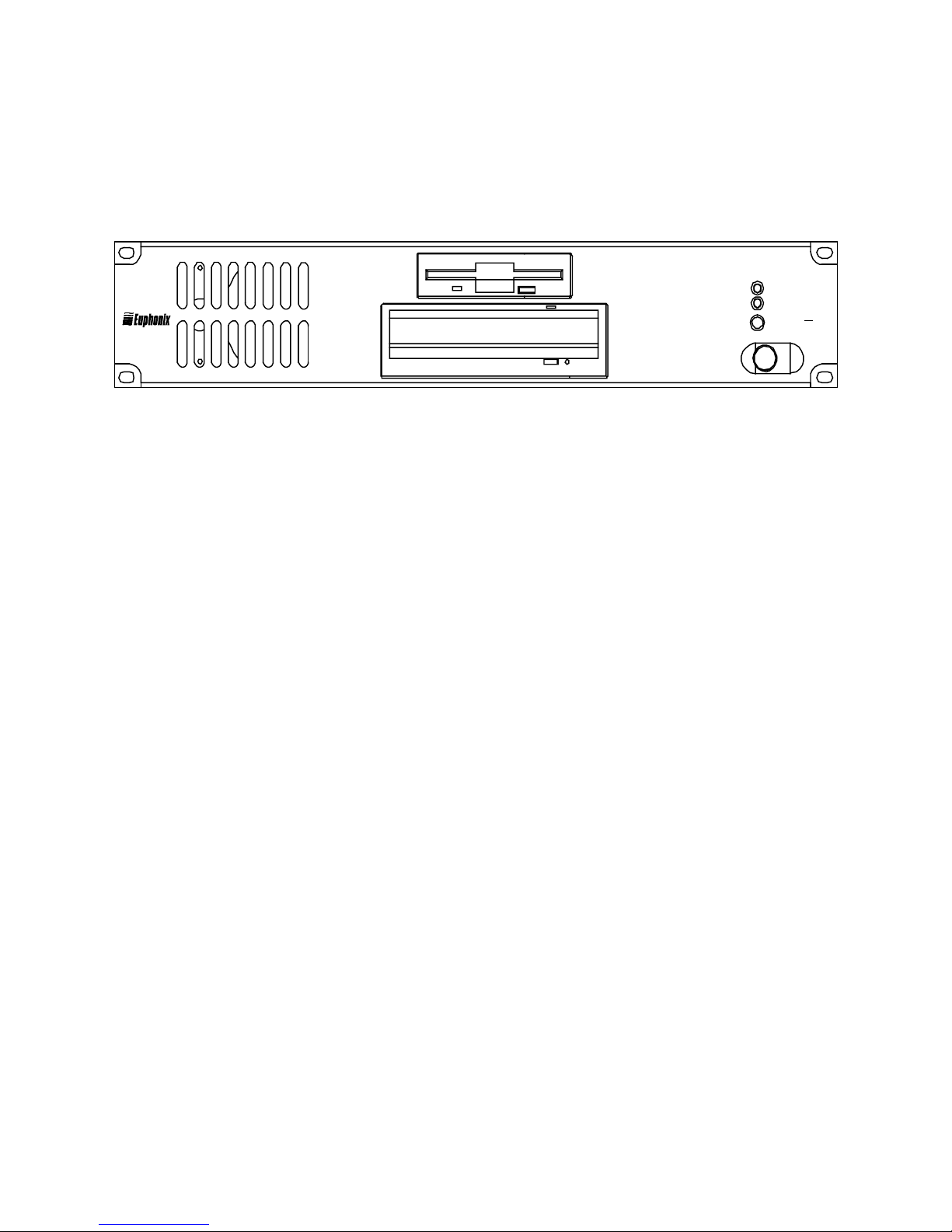
Front Panel
Dimensions
Height: 3.5 inches
Width: 19 inches
Depth: 18 inches
Weight: 25 lbs
PILOT COMPUTER
OS DRIVE
SCSI
RESET
PC
252
Front Panel Features
3.5” Floppy Drive For upgrading system software, back up of Title files, or other system
housekeeping duties.
24X CD ROM Drive For upgrading system software.
OS Drive LED Indicates the Operating System (DOS) drive is active.
SCSI LED Indicates Pilot SCSI network is active. This is currently not implemented.
Reset Button Can be used for a ‘warm’ reboot of Pilot. This button is recessed into the front
panel so it will not be accidentall y pressed.
Power Switch On/Off button lights when unit is powered up.
THERE ARE NO USER SERVICEABLE PARTS IN THE PILOT COMPUTER
©1999 Euphonix, Inc. Page 6 Pilot Computer Manual
Page 7
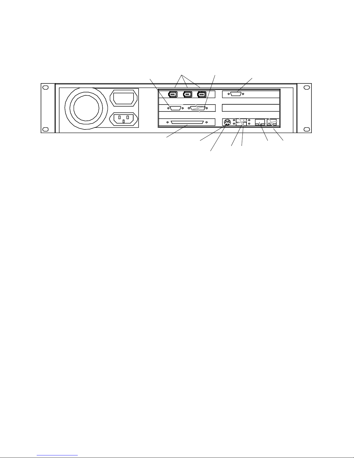
Rear Panel
Trackball &
Parallel Port
Remote
IEEE 1394
Connect one
to Hub
REMOTE
NOT USED
Video Monitor
Attach TFT
TFT
MOUSE
KBD
USB Ports
NOT USED
USB
NTWK 1
Primary
Network
Port
NTWK 2
Network Port
N
OT USED
SCSI – port
may be used
with proper
set-up
SCSI
Keyboard
Y-connector
Video Connector (15 Pin D sub) The video monitor (TFT) is connected h ere. This video cable
either be a long run (10 met ers) from the Remote stand or a short run from an
extender box.
USB Ports (USB) Universal serial Bus ports. A USB modem can be connected here, but is
not currently configured for any purpose.
Network Port 1 (RJ45) A Local Area Network (LAN) can be connected at this port to give the
Pilot computer access to networked resources including Internet access if your facility
is so equipped.
Network Port 2 (RJ45) A second Local Area Network (LAN) can be connected at this port to
give the Pilot computer access to a separate set of networked resources. This
attachment of a second network will require further software configuration.
Trackball & Keyboard (PS2) Connect the Y-cable marked KYBD and MO USE here.
IEEE 1394 Ports (1394) These ports are used for connection to IEEE1394 ports on the Studio
Hub and Audio Deck. 1394 carries control, status and feedback communication.
Remote (9 pin D sub) This port accepts the RS232/422 adapter and Remote cable, or
just the RS232 serial cable if an extender s ystem is supplied. When an extender is
used the RS232-to-RS422 conversion takes place at the Remote.
SCSI (68 pin D-sub female) This port connects to exter nal S CSI devices such as JAZ
drives, CD-R, or Kingston-mounted hard riv es. The port is software enabled but not
typically used. Please check with Euphonix R-1 support to configure the port for
actual use.
Power Connector (IEC) The IEC power connector accepts standard IEC power cords. A
switching power supplied is used so voltages from 110volts to 240 volts, 50 or 60
cycle, can be input.
©1999 Euphonix, Inc. Page 7 Pilot Computer Manual
Page 8

Technical Specifications
Performance Specifications
Pentium III, 933 MHz, 256 MB RAM, 10 GB HD storage
3D/2D accelerated graphics at 1024 X 768 pixels with 16-bit color
Peak Program Metering per IEC 268-10A
400 Mbit IEEE 1394 interface
Ultra wide SCSI co ntroller
10Base-T/100Base-T Ethernet network co ntroller
USB 1.0 interface
Power Requirements
110, 220, or 240 VAC at 50 or 60 Hz
Environmental Requirements
5 to 35 degree Centigrade
Specific Sub-systems or Performance Con siderations
IEEE 1394
The R-1 Pilot Computer isolates itself from the actual audio processing (recording)
components. Each component runs its own operating system (which can be
downloaded from the Pilot) and communicates with the Pilot and other components
via 1394. This control backbone is designed for 400 MBit operation.
©1999 Euphonix, Inc. Page 8 Pilot Computer Manual
Page 9

User Reference
Installing New Versions of R-1 Software
Follow this procedure to ensure prop er installation of R-1 software upgrades:
1) Power on the R-1 Pilot computer.
2) Insert the CD ROM or disk ettes that contai n the R-1 software into the CD ROM
or floppy drive.
3) Find the SETUP.EXE file and double click on it. This will install t he new
version of R-1 software. DO NOT START THE R-1 SOFTWARE
4) Exit Windows and power down the R-1 Pilot.
5) Disconnect at the Pilot the 1394 cable (green) that runs from the Pilot to the
Studio Hub. There should be no 1394 connection from the Pilot to the Studio
Hub.
6) Disconnect at the Studio Hub the 1394 cable (green) that runs from the
Studio Hub to the first Audio Deck. There should b e no 1394 connection from
the Audio Deck or the Pilot to the Studio Hub.
7) Reconnect the 1394 cable (green) that runs from the first Audio Deck back to
the Pilot.
8) Power on the Pilot and Audio Deck.
9) Start the R-1 software by double clicking on th e R-1 Multitrack Recorder icon.
Choose Cancel when you get the message that a Studio Hub cannot be found.
10) The software will load new code to the Audio Deck(s) and the R-1 Application
will show on the screen.
11) Close the R-1 Application, e xit Windows and power down the Pilot and Audio
Deck.
12) Disconnect at the Pilot the 1394 cable (green) that runs from the first Audio
Deck to the Pilot, and reconnect this cable to the Studio Hub.
13) Reconnect the 1394 cable (green) that runs from the Studio Hub back to the
Pilot.
14) Power on the Pilot, Audio Deck, and Studio Hub.
15) Start the R-1 software by double clicking on the R-1 Multitrack Recorder icon.
16) The software will boot the Audio Deck and load new code to the Studio Hub
and the R-1 application will s how on screen.
17) Exit Windows and power down the Pilot, Audio Deck and Studio Hub. The
software upgrade is now complete.
©1999 Euphonix, Inc. Page 9 Pilot Computer Manual
Page 10

Network Configurati on
The Pilot computer Windows operating software has been made network ready by
the installation of the following:
1) Client for Microsoft Networks
2) Built-in Fast Ethernet Adapter
3) TCP/IP
Still it essential that if you are configuring your R-1 for use on a network, yo ur
facility’s network and systems administrator must ensure that:
1) The physical network is built properly
2) Servers and other nodes on the network are co nfigured correctly
3) Window98 networking features on the R-1 are configured correctly
Euphonix cannot take responsibility for the configuration of your network unless
specific contractual arrangements ar e made with Euphonix for these services in
advance. If you do not have the expertise on hand to manage a networked
installation, then DO NOT NETWORK your R-1.
To connect your Pilot computer to an Ethernet network:
a) Power on the Pilot computer
b) After boot up, right-click on the Network Neighborhood icon.
c) Left-click on Properties.
d) Click on the Identification tab.
e) Enter a computer name that is unique on your network. Check with your
facility network administrator to answer this question. The Computer Name,
which you enter, must b e an alpha-only or alphanumeric character string of
no more than 15 characters. You may use hyphens, but you may not use
any other symbols. You also cannot use spac es, and you cannot use
exclusively nume ric names.
f) Enter the name of the workgroup or domain in which you want the
computer to communicate. Check with your facility systems administrator
to answer this question.
g) Click OK.
h) Power down the Pilot computer
i) Connect a RJ45 network cabl e to the back of the Pilot co mputer.
j) Power up the Pilot. Enter your network password when prompted by the
opening dialog box.
©1999 Euphonix, Inc. Page 10 Pilot Computer Manual
Page 11

Monitor Fine Tune
Here is a method of fine tuning the Hitachi TFT monitor that is part of the R-1
system. This procedure will assure that you are getting the best performance that this
monitor can provide.
There is a floppy diskette labeled ’Utility Di sk for Windows’ that shipped with the
Hitachi monitor in the bag with the monitor manual. This diskette contains a test
pattern file the monitor can use to automatically optimize its settings.
To view the test pattern on the monitor screen:
• Insert the diskette in the Pilot Computer floppy drive.
• Double click on the Floppy Drive ico n.
• Double click on the Testpat.exe icon.
• On the Hitachi monitor, press the Menu button.
• Use the > button to scroll to Auto Adjust.
• Press the + button. The program will take 10 seconds or so to adjust the monitor
settings. During this time, the menu will disappear.
• When the menu reappe ars, the adjustment is finished. Click a nywhere or press
any key to exit the test pattern.
• Close the Floppy Drive Windo w and Remove the floppy diskette.
Safe Mode
The Windows operating system has a feature c alled Safe Mode that is designed to
warn users about possible Windows configuration problems. In Safe Mode, the Pilot
computer uses only the minimum necessary res ources to run until the problem can be
resolved. You will not have access to CD-ROM drives or printers while in Safe Mode.
Safe Mode can be rec ognized by a change in sc reen resolution that will make all the
objects on the screen appear larger and blurry. If Safe Mode is encountered, we
recommend turning the Pilot off and back on per the Power Down and Power On
instructions below. This will often resolve a Safe Mode issue. If this fails to start
Windows in normal mode, contact Euphonix R-1 S upport: (425) 485-3132.
Power On Sequence
Euphonix recommends that when powerin g on the R-1 system, that the Studio Hub
and the Audio Deck be powered on at roughly the same time as the Pilot computer.
This will ensure that the Pilot’s operating system will recognize the Euphonix
components attached to IEEE 1394 with minimal 1394 bus resets. There is no actual
requirement for any particular boot sequence. Be sure that the video monitor has
been turned on. The video monitor may display th e message No sync signal when
initially powered up.
©1999 Euphonix, Inc. Page 11 Pilot Computer Manual
Page 12

Pilot boot up takes about 40 seconds. Near the end of the boot up you will see a
dialog box that asks you for a network password. If you are connected to a network,
enter your password now and clic k OK. If you are not on a network, press ESC on the
keyboard. The software will finish booting.
Once the Pilot has been powered on, its boot up procedure should not be
interrupted. If you need to power down the Pilot, wait until the Euphonix opening
screen graphic appears and follow the steps in the following Power Down procedure.
R-1 Application Boot up
After power on and boot up of all the R-1 system components, start the R-1
Application software by double-clicking on the R-1 Multitrack Recorder icon in the
opening screen graphic. You will s ee a progress bar that informs you of boot up
status. The R-1 software Mult itrack Screen should appear in less than 15 seconds.
The R-1 will boot up the 1394 attached components du ring this time.
Audio Deck #1, then if present #2, #3, and #4.
Studio Hub
Then you will get any messages relating to the Audio Drives currently installed in
the system. If the drives are inserted into the bays where they were formatted the
bott process will continue without messages.
Finally the R-1 Application will report that it is sending Title files to the host from
the first Audio Drive (typically deck #1, disk #1).
Power D own Seq u e n c e
Please use the following steps to power down the Pilot computer:
1) If the R-1 Application is open, then close it by clicking on the "X" in the
upper right hand corner of the screen-b ased interface. Save the Title if
prompted and as desired. The R-1 Application may take a moment to close as
it is cleaning up all R-1 file management. You will then be presented with
the Windows desktop.
2) From the Windows desktop, guide the cursor into the lower left hand corner
of the screen to the Start button. Left-click on the Start button and a menu
will appear.
3) Left-click on the lowest item in the menu; Shut Down. A dialog will appear in
the center of the screen.
4) Click on Shut Down. Click on OK.
5) Wait until you are presented with a screen that states, It is now safe to shut
down R-1 Pilot.
6) Press the power button on the front of the Pilot.
©1999 Euphonix, Inc. Page 12 Pilot Computer Manual
Page 13

Resetting 1394 Drivers:
The 1394 Drivers may need to be reset if your R 1 is having difficulty operating
properly after a crash where a 1394 error dialog was shown on the screen, or if the
Pilot continues to crash every time you boot Windows. Follow these steps to reset
1394 communications.
1) Unplug all 1394 cables from the Pilot computer.
2) Make sure that there are no 1394 cables connecting the Studio Hub to any Audio
Deck. Also make sure that multiple Audio Decks are not connected to each other
via 1394.
3) Shut down the Pilot computer and turn off the Studio Hub and any Audio Decks.
4) Power up the Pilot computer, Studio Hub and Audio Deck( s).
5) Right click on the My Computer icon (in the Windows desktop) and select
“Properties”. This will open up the Windows System Properties dialog box.
6) Left click on the Device Manager tab at the top of the System Properties dialog
box.
7) Connect an Audio Deck to the Pilot computer with a 1394 cable.
8) In the Device Manager you will see the “Euphonix R1 IEEE-1394 Drivers” appear.
Left click on this and it will expand d o wn and show its contents. You should now
see the “Euphonix R1 Audio Deck” Select R1 Audio Deck and click on Remove.
9) Unplug the Audio Deck 1394 from the Pilot computer.
10) Repeat this operation (steps 7-9) for each of the Audio Decks in your system.
11) Connect the Studio Hub to the Pilot computer with a 1394 cable.
12) In the Device Manager you will see the “Euphonix R1 IEEE-1394 Drivers” appear.
Left click on this and it will expand d o wn and show its contents You should now
see the “Euphonix R1 Studio Hub”. Select R1 Studio Hub and click on Remove.
The Audio Deck will not appear there, because you have disconnected it.
13) Unplug the Studio Hub from the Pilot computer.
14) Shut down the Pilot computer and turn off the Studio Hub and Audio Deck.
15) Power up the Pilot computer, Studio Hub an d Audio Deck.
16) Right click on the My Computer Icon (in the Windows desktop) and select
“Properties”. This will open up the Windows System Properties dialog box.
17) Left click on the Device Manager tab at the top of the System Properties dialog
box.
18) Connect the Audio Deck to the Pilot computer with a 1394 cable. A Windows
dialog may appear, stating, “Looking for Device”.
©1999 Euphonix, Inc. Page 13 Pilot Computer Manual
Page 14

19) In the Device Manager you will see the “Euphonix R1 IEEE-1394 Drivers” appear.
Left click on this and it will expand d o wn and show its contents. You should now
see the “Euphonix R1 Audio Deck”. After this appears, disconnect the Audio Deck
1394 cable from the Pilot.
20) Repeat this operation (steps 18-19) for each of the Audio Decks in your system.
21) Connect the Studio Hub to the Pilot computer with a 1394 cable. A Windows
dialog may appear, stating, “Looking for Device”.
22) In the Device Manager you will see the “Euphonix R1 IEEE-1394 Drivers” appear.
Left click on this and it will expand d o wn and show its contents. You should now
see the “Euphonix R1 Studio Hub”. After this appears, disconnect the Studio Hub
1394 cable from the Pilot.
23) Shut down the Pilot computer and turn off the Studio Hub and Audio Deck.
Connect the Studio Hub and Audio Deck to Pilot computer with 1394 cables.
24) Power up the Pilot computer, Studio Hub an d Audio Deck.
Your R1 1394 communications should now be reset.
If for any reason you encou nter a device that will not show up in the list bene ath
“Euphonix R1 IEEE-1394 Drivers“ then that co mponent may have a problem.
©1999 Euphonix, Inc. Page 14 Pilot Computer Manual
Page 15

If the R-1 Operating System must be Reinstalled
If your R-1 system is not working to the point where you think you need to
reinstall the operating system, then you should call R-1 product support.
Completely rewriting the OS disk: Your R-1 documentation and software
includes a CD-ROM entitl ed R-1 Operating System Image and a floppy entitled R-1
Boot Disk – R-1 Recovery. If you boot the R-1 Pilot with the floppy and CD-ROM
loaded into their respective drives, this will automatically reload al l software in your
R-1 to a known working configuration. This method completely erases all data and
programs from the R-1 Pilot and rebuilds the software components cleanly to the
configuration that shipped from the factory.
Under typical circumstances there s hould be nothing absolutely essential on the
R-1 Pilot, so replacing all disk contents in one operation is the best solution and the
most reliable. However, there are circumstances where you might n eed to save data
from the R-1 first. Pleas e read and consider the following. The saving of data from
the R-1 Pilot is not generally considered necessary and is not made easy by either
software or data organization. You should be reasonably adept at using the Windows
operating system.
Safety Copies of All Titles Saved from this machine will be lost. A Safety copy
of each Title is written to the host file syst em of the R-1 Pilot whenever the Title is
being saved. The master copy is written to the audio disk and will automatically be
restored to the system whenever that drive is loaded. The Safety copy is only an
extra back-up to the master copy. Euphonix recommends that you back up recent
Safety Tiles to a floppy when you ar e backing up the audio. If you are about to erase
the contents of the R-1 Pilot, you may want to get some or all of these files from the
Safety Titles dir ectory.
C:\EUPHONIX\TITLES\*.*
Because Titles can be backed up regul arly, there are shortcuts for copying thes e
files. The Safety Titles directory can be accessed directly from the Start Menu in
Windows 98SE. Select the desired files within this window and drag the f iles to the
the 3½ Floppy (A) displayed on the Desktop.
Exported Sound Files will be lost. When you export a Sound File to WAV format
on the host it typically is stored in –
C:\EUPHONIX\SOUND FILES\
Because Sound Files are intended for uses sep arate from the R-1, there are
shortcuts for copying these files. The Sound Files directory can be accessed directl y
from the Start Menu in W indows 98SE. Launch th is window and select the desired
files. You will probably want to launch the Windows Explorer found under Programs
of the Start Menu, then navigate to a network drive large enough for exported audio.
Typically these files are too large for a floppy diskette. If the exported sounds are
short enough to be less than 1.4 MB, they can be dragged to the 3½ Floppy (A)
displayed on the Desktop.
©1999 Euphonix, Inc. Page 15 Pilot Computer Manual
Page 16

Pre-calculated waveform data will be lost. Typically th is should be acceptable.
The waveforms will be r ec alculated as needed. In many instances this will be the
quickest option in that it does not require your intervention at all. However, if you
think that you will sa ve time and that waveform s are essential to a project in
progress, then you may save and subs equently restore these files. Please be
forewarned, waveform caching files are large –
C:\EUPHONIX\SYSTEM\*.IMG
****EXCEPT DO NOT SAVE*****
wboot48.img or wboot96.img
Safety Copies of All Disk Directories written from this machine will be lost. A
Safety copy of each Audio Disk Directory (also called a Table of Cont ents or TOC) is
written to the host file system of the R-1 Pilot whenever the disk drive is being
saved. The master copy is written to the audio d isk and will automatically be
restored to the system whenever that drive is loaded. The Safety copy is only an
extra back-up to the master copy. As with any safety system, there is no guarantee
that the safety copy will be the most current and desirable version of the disk.
Further there is no wa y for the user to direct the m ac hine to use a safety copy of a
Disk Directory. Instead t he R-1 evaluates the TOC of any newly loaded di sk then
determines to try to use the safety copy if there appears to be a problem. For this
reason you would only be interested in backing up this information if you were
having problems or suspected problems with a disk already.
C:\EUPHONIX\SYSTEM\*.FMT
Please Note: It is very seldom productive to go through the step of reloading all
the software components of your R-1. Although it is a po pular approach with
Windows, where there are many differing prog rams all working within the same
operating environment, and where programs are loaded and unlo aded all the time,
the R-1 is a closed system. There i s little actual likelihood of corruption in the
operating system. In those rare instances where the R-1 fails, experience generally
shows it is a cabling problem or damage to a component while in transit.
Before electing to reload all software you should consult with R-1 Technical
Support or Euphonix Field Support. Our staff will gladly help you analyze the
situation and also help in evaluating it ems that should be saved before re-writing th e
disk. It may also be possible that Euphonix staff will recommend simply reloading
Windows 98SE. This is done by inserting a Windows 98SE CD-ROM and running (select
Run from the Start Menu) D:\WIN98\SETUP.EXE. In the following section you will
find all the typical set ting for Windows 98SE. If y ou use the Operating System Image
as described above all of thes e settings will be established automatically. However,
using either method, it may be necessary to –
• Reload the most current R-1 Application software version (from its separate CD-
ROM)
• Re-establish your network connection
• Re-tune your monitor
©1999 Euphonix, Inc. Page 16 Pilot Computer Manual
Page 17

Windows 98SE Settings
If Windows 98SE needs to be rein stalled on the Pilot computer for any reason, you
may need to reestablish some settings that R-1 needs to run properly. The following
sections will help you restore any settings that may have been changed by the
reinstallation of Windows 98SE.
Internet Explorer Security Settings
1) Right-click in the Internet Explorer icon and select Properties. Click on the Security
tab. Select the Internet zone, and verify security is set to MEDIUM, (to enable
access to the Spectral/Euphonix BBS site).
2) Select the Local Intranet zone. Set th e Security level for the zone to Custom. Click
on the Settings button. Enable ALL the settings for Active X controls, 5 settings
total. Click on OK to save settings.
3) Close the Internet Properties menu.
Install Display Drivers
1) Install the Video Mon it o r D isplay drivers for the vid eo card, using the ATI CD-ROM
provided with the system.
2) Select the EASY INSTALL option, follow the directions, select the EXPRESS Setup
option.
3) Let the computer reboot after installing the drivers, de-select the option to show
the ATI menu each time the co mputer is rebooted, and close the menu.
Display Settings
1) Right click anywhere on the desktop and select Properties to change the display
properties.
2) Click on each of the fo llowing tabs in sequence to change the settings in each
category.
3) Settings tab - for Colors choose High Color (16-bit).
4) Settings tab - for Screen Area choose 1024x768.
5) Settings tab – Click on Advanced.
6) Settings tab – under Advanced Dialog, General tab – for Font Size choose Small
Fonts.
7) Settings tab – under Advanced Dialog, Monitor tab – this should show Plug and
Play monitor – place check next to Automatically detect Plug and Play monitor,
and another check next t o R eset Display on suspend/resume. If you are using a
terminal extender product, you may not be able to use Plug and Play. The
Hitachi monitor is CML150X.
©1999 Euphonix, Inc. Page 17 Pilot Computer Manual
Page 18

8) Settings tab – under Advanced Dialog, Adjustment tab – for Display Device choose
CML150X.
9) Settings tab - under Advanced Dialog choos e OK at the bottom.
10) Background tab – for Wallpaper HTML or Picture select R-1 Desktop.
11) Background tab – for Wallpaper Display select Center.
12) Screen Saver tab – for Screen Saver select (None)
13) Screen Saver tab – under Energy Saving Features, click on the Settings button.
14) Screen Saver tab – under Power Management Properties dialog, fo r Power schemes
choose Always On.
15) Screen Saver tab – under Power Management Properties dialog, fo r Turn Off Moni tor
choose Never.
16) Screen Saver tab – under Power Management Properties dialog, fo r Turn Off Hard
Drives choose Never.
17) Screen Saver tab – under Power Management Properties dialog, cl ick on Apply (this
is required).
18) Screen Saver tab – under Power Management Properties dialog, cl ick on OK.
19) Appearance tab - for Scheme select R1. If there is no R1 Scheme, then you will
have to edit each Item of the Appearance separately. See the next page for a
complete table of settings for the R1 color scheme. The R-1 is dependent on this
system color scheme for certain user interface elements that it presents. Without
the correct color scheme the R-1 may not be as easy or intuitive to use.
20) Click on APPLY to save these settings (without re-starting).
21) Also under Settings, Advanced, select the Adjustment tab, click on the Refresh
Rate button, and select 60 Hz.
22) Click on APPLY and OK to save these settings.
23) With a Hitachi TFT connected, Windows 98SE should automatically detect the
display type, Hitachi CML150X. If any brand of Extender is installed, the display
type may come up as “Unknown Monit o r.” In that case the above settings may
have to be restored manually.
©1999 Euphonix, Inc. Page 18 Pilot Computer Manual
Page 19

ITEM Size Color Color 2 Font Font
Size
3D Object 128, 128, 128
Active Title Bar 18 0, 0, 0 96, 96, 96
Color/style
Active Window
1 128, 128, 128
Border
Application
85, 85, 85
Background
Caption Button 18
Desktop 0, 0, 0
Icon 32
Icon Spacing
43
(Horizontal)
Icon Spacing
43
(Vertical)
Inactive Title
18 88, 88, 88 128, 128, 128
Bar
Inactive
1 128, 128, 128
Window Border
Menu 18 128, 128,128 MS Sans Serif
(Western)
Message Box MS Sans Serif
(Western)
Pallette Title MS Sans Serif
(Western)
Scrollbar 16
80, 0, 0
80, 0, 0
80, 0, 0
Bold
Selected Items 18 0, 0, 128 MS Sans Serif
8 255, 255, 255
(Western)
Tool Tip 255, 255, 255 MS Sans Serif
80, 0, 0
(Western)
Window 255, 255, 255
©1999 Euphonix, Inc. Page 19 Pilot Computer Manual
Page 20

Network Settings
1) Right click on the Network Neighborh ood icon, select properties, and select the
Identification tab. Verify the name you entered for the computer during the
Windows 98 setup process.
2) Also in the Identification tab, verify the workgroup is your company name or
whatever your systems administrator has ass igned.
3) Click on the Access Control tab. Verify the share-level option is s elected.
4) Connect the computer to the network, if ava ilable, reboot the computer, and log
onto the network. Verify that the network connection is established (try
navigating to a network directory).
Windows Explorer Settings
1) Start Windows Explorer, (double click on the windows explorer icon) se lect the C:
drive, and make the following changes:
2) Select the View pull- down menu, de-selec t “view as web page”, and select
“details”.
3) Select the View pull down menu again, sel ec t “folder options”, select the View
tab, and make the following settings:
4) Select remember each folder’s settings,
5) Select show all files.
6) De-Select hide file extensions.
7) Select OK to save the settings.
©1999 Euphonix, Inc. Page 20 Pilot Computer Manual
Page 21

©1999 Euphonix, Inc. Page 21 Pilot Computer Manual
 Loading...