

Page 1
Euphonix System
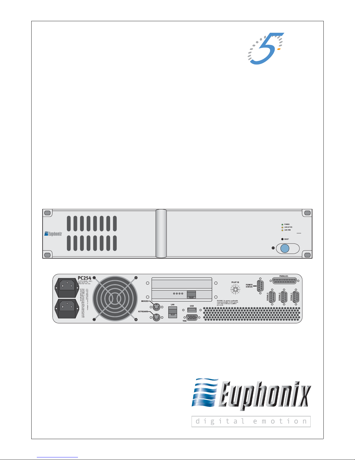
Euphonix PC 254H
System 5 Hybrid Pilot
Operation Manual
Document Revision: C
Software Version: Internal v7.385
Part Number: 840-10067-01
Release Date: June 2007
EUCON HYBRID PILOT COMPUTER
Euphonix, Inc.
220 Portage Ave.
Palo Alto, California 94306
Phone: 650-855-0400
Fax: 650-855-0410
Web: http://www.euphonix.com
e-mail: info@euphonix.com
PC
254h
??
Page 2

In the interest of continued product development, Euphonix reserves the right to make improvements
to this manual and the product it describes at any time, without notice or obligation.
System 5, S5, PatchNet, eMix, EuCon, R1, Studio Hub, Audio Deck, Max Air, Reel Feel, Clear
Displays, Track Panner, SnapShot Recall, DSC (Digital Studio Controller), Hyper-Surround, Total
Automation and Mix View are trademarks of Euphonix, Inc.
Manual design and editing by Rob Wenig.
Manual written by Storm Staley, Martin Lucas, Chris Konovaliv, Edward Jones, and Rob Wenig.
©2007 Euphonix, Inc. All rights reserved worldwide. No part of this publication may be reproduced,
transmitted, transcribed, stored in a retrieval system, or translated into any language in an y f orm
by any means without written permission from Euphonix, Inc.
Note: This equipment has been tested and found to comply with the limits for a
Class A digital device pursuant to Part 15 of the FCC Rules. These limits are
designed to provide reasonable protection against harmful interference when
the equipment is operated in a commercial environment. This equipment
generates, uses, and can radiate radio frequency energy and, if not installed
and used in accordance with the instruction manual, may cause harmful interference to radio communications. Operation of this equipment in a residential area is likely to cause harmful interference in which case the user will
be required to correct the interference at his own expense.
Caution:Any changes or modifications made by the user that are not expressly ap-
proved by Euphonix could void the user’s right to operate the equipment.
Page 3

IMPORTANT SAFETY INSTRUCTIONS
The lighting flash with arrowhead symbol within an equilateral triangle, is intended to alert
the user to the presence of uninsulated “dangerous voltage” within the product’s enclosure
that may be of sufficient magnitude to constitute a risk of electrical shock to persons.
The exclamation point within an equilateral triangle, is intended to alert the user to the
presence of important operating and maintenance (servicing) instructions in the literature
accompanying the product.
1) Read these instructions.
2) Keep these instructions.
3) Heed all warnings.
4) Follow all instructions.
5) Do not use this apparatus near water.
6) Clean only with a dry cloth.
7) Do not block any ventilation openings. Install in accordance with the manufacturer’s instructions.
8) Do not install near any heat sources such as radiators, heat registers, stoves, or other apparatus
(including amplifiers) that produce heat.
9) Do not defeat the safety purpose of the polarized or grounding-type plug. A polarized plug has
two blades with one wider than the other. A grounding type plug has two blades and a third
grounding prong. The wider blade or the third prong are provided for your safety. If the provided
plug does not fit into your outlet, consult an electrician for replacement of the obsolete outlet.
10) Protect the power cord from being walked on or pinched particularly at plugs, convenience
receptacles, and the point where they exit from the apparatus.
11) Only use attachments/accessories specified by the manufacturer.
12) Use only with the cart, stand, tripod, bracket, or table specified by the manufacturer, or sold
with the apparatus. When a cart is used, use caution when moving the cart/apparatus combination to avoid injury from tip-over.
Page 4

13) Unplug this apparatus during lightning storms or when unused for long periods of time.
14) Refer all servicing to qualified service personnel. Servicing is required when the apparatus has
been damaged in any way, such as power-supply cord or plug is damaged, liquid has been
spilled or objects have fallen into the apparatus, the apparatus has been exposed to rain or
moisture, does not operate normally, or has been dropped.
15) WARNING – TO REDUCE THE RISK OF FIRE OR ELECTRIC SHOCK, DO NOT EXPOSE
THIS APPARATUS TO RAIN OR MOISTURE.
16) Do not expose this equipment to dripping or splashing and ensure that no objects filled with
liquids, such as vases, are placed on the equipment.
17) To completely disconnect this equipment from the AC Mains, disconnect the power supply
cord plug from the AC receptacle.
18) The mains plug of the power supply cord shall remain readily operable.
19) This unit is provided with a power supply cord set suitable for 120V AC input only (for U.S.A.
and Canada). For other than U.S.A. and Canada, a qualified person must provide for use with
this unit, an appropriate, approved power supply cord set which is in compliance with the end
use country requirements and has a minimum cross-sectional area of 1.0mm2.
20) For units with more than one power cord:
Caution: This unit has more than one power supply cord. Disconnect two power supply
cords before servicing to avoid electrical shock.
Attention:Cet appareil comporte plus d’un cordon d’alimentation. Afin de prévenir les
chocs électriques, débrancher les deux cordons d’alimentation avant de faire le
dépannage.
21) Operator Accessible Fuse:
Caution: For continued protection against risk of fire, replace only with same type and
rating of fuse.
Attention:Pour ne pas compromettre la protection contre les risques d’incendie, remplacer
par un fusible de même type et de même caractéristiques nominales.
Page 5

Euphonix System 5 Hybrid Pilot Operation Manual
Table of Contents
Chapter 1: Installation and Configuration ............................................................7
1.1 Introduction ...............................................................................................7
1.2 System 5 PC Software...............................................................................7
1.3 Hybrid Pilot Connection and Configuration..............................................7
1.3.1 Network Connections..................................................................8
1.3.2 KVM Connection (Optional)......................................................8
1.4 Workstation Setup.....................................................................................9
1.4.1 Network Configuration...............................................................9
1.4.2 EuCon Software Installation.......................................................9
Chapter 2: Console/Workstation Operations....................................................11
2.1 System 5 PC Startup................................................................................11
2.2 Hybrid Operations...................................................................................11
2.2.1 Assigning Workstations and Tracks .........................................11
2.3 Application Sets.......................................................................................12
2.4 Steinberg Nuendo....................................................................................12
2.4.1 Configuration............................................................................12
2.5 Merging Technologies Pyramix..............................................................14
2.5.1 Configuration............................................................................14
2.5.2 Plugin Integration......................................................................17
2.6 HUI Applications.....................................................................................18
2.6.1 Digidesign Pro Tools ................................................................18
2.7 Mackie Control Universal .......................................................................24
2.7.1 Final Cut Pro and Soundtrack Pro.............................................24
2.8 DAD AX24 Microphone Preamplifier....................................................26
v
Page 6

Euphonix System 5 Hybrid Pilot Operation Manual
vi
Page 7

Euphonix System 5 Hybrid Pilot Operation Manual
Chapter 1: Installation and Configuration
This chapter introduces the Hybrid Pilot and instructs you how to configure it and the
Euphonix System 5 console to work together.
1.1 Introduction
As digital audio workstations become more prevalent in the audio production environment, it is vital to smoothly integrate them into the production workflow. The
Euphonix MC and System 5-MC products are full-featured control surfaces able to
control and communicate with multiple software products (Nuendo, Logic, Pyramix,
Pro Tools, etc.).
The System 5 Hybrid Pilot brings that functionality into the System 5 console:
• Tracks can be loaded from DAWs onto the console surface.
• SmartSwitch functionality enables DAW control and editing directly from the
console surface.
• Tracks from different DAWs co-exist on the surface alongside tracks from regular System 5 sources, enabling simultaneous use of many different sources
and total control of the studio from the console.
1.2 System 5 PC Software
Before proceeding make sure your components are up-to-date:
• System 5 software must be version 3.00 or higher.
• System 5 Studio Computer SC262/263 must be imaged with .v03 or higher.
• See System 5 Manual for step-by-step installation instructions.
1.3 Hybrid Pilot Connection and Configuration
The Hybrid Pilot arrives with its software installed and configured, but it must be connected properly.
The first time the Hybrid Pilot is booted after connecting to the System 5, it will check
for new software and automatically update itself. This process may take a few minutes
and briefly delay the Hybrid being visible in eMix.
7
Page 8

Euphonix System 5 Hybrid Pilot Operation Manual Installation and Configuration
1.3.1 Network Connections
The Hybrid Pilot has two Ethernet ports on the rear panel, one above the other. All connections should be made with straight-through Category 5 network cables.
1. Connect the bottom port to the System 5 console network switch.
2. Connect the top port to the included DHCP-capable network router. The Hy-
brid Pilot ships with DHCP enabled (on the network adapter with the top port),
allowing it to automatically obtain an IP address.
NOTE: Do NOT connect your DAWs to the System 5 console network switch.
For fixed IP configurations please see your netowrk administrator.
1.3.2 KVM Connection (Optional)
The Hybrid Pilot can use the Ontrack ADU-200 relay device (available from Euphonix)
to control a KVM (keyboard/video/mouse) switch with an RJ-45 port, such as the Gefen
eX-Tend-It series. To implement this functionality:
1. Connect the video outputs of your workstations to the KVM inputs.
2. Connect the KVM video output to your main display.
3. Connect the Ontrack ADU-200’s USB plug to one of the Hybrid Pilot’s rear
panel USB ports.
4. Connect a shielded RJ-45 Ethernet cable from the Ontrack’s RJ-45 port to your
KVM’s RJ-45 port.
The cable MUST BE SHIELDED or the switching will not function properly.
Check that the RJ-45 connectors have metal ends.
Now when a Workstation key is pressed on the CM401 subpanel, the Hybrid Pilot sends
a switch command to the KVM and changes your display to reflect that KVM input.
NOTE: Since the Hybrid Pilot does not know the order your workstations were con-
nected to the KVM, we recommend assigning the workstation attached to
KVM input 1 to the first workstation listed in the subpanel, the workstation attached to KVM input 2 to the second workstation listed, etc.
8
Page 9

Euphonix System 5 Hybrid Pilot Operation Manual Installation and Configuration
1.4 Workstation Setup
EuCon is a high-speed audio data transfer protocol created by Euphonix. EuCon-aware
applications (Nuendo, Pyramix, Logic) offer full control through EuCon commands,
while Mackie Control Universal and HUI emulation over the EuCon connection enables control of Pro Tools and other software.
Each DAW must be networked with the Hybrid Pilot and the EuCon software must be
installed to enable EuCon control and communication.
1.4.1 Network Configuration
Using straight-through RJ-45 Ethernet cables, connect your workstation(s) to the LAN
ports on the included DHCP-capable network router.
NOTE: You have now created a small local area network comprised of just the Hybrid
Pilot and your workstation(s). To access an outside network, such as a st udio
facility LAN or the Internet, connect the WAN port on the router to your studio’s
network switch, or to your cable/DSL modem.
The DHCP server in the included router hands out IP addresses to the devices connected
to its LAN ports: the Hybrid Pilot and your workstation(s). This allows easy plug-andplay network configuration. For this reason, the router must be turned on before the
Hybrid and your workstation(s).
1.4.2 EuCon Software Installation
Install the EuCon software on every workstation connected to the Hybrid Pilot through
the DHCP-capable router. Check www.euphonix.com for updated versions of the EuCon software.
NOTE: The EuCon software also serves to communicate with the Euphonix MC/Sys-
tem 5-MC products, and contains references to those products.
1. Insert the Euphonix S5 Software Installation CD in your workstation’s CD/
DVD drive.
In Mac OS X, double-click the CD icon on the desktop, and double-click the
EuConWS package in the workstation software folder.
The Install program launches. Proceed to Step 3.
9
Page 10

Euphonix System 5 Hybrid Pilot Operation Manual Installation and Configuration
2. To proceed with installation:
a. Minimize all programs.
b. Double-click My Computer on the desktop to display the drives on your
computer.
c. Double-click the CD/DVD drive.
d. Double-click the EuConWS executable file in the workstation software folder.
The Setup Wizard opens.
3. Click Next and choose a directory to install the software.
The default Windows directory is C:\Program Files\Euphonix\EuCon.
The default Macintosh OS X directory is the Applications folder.
4. For Windows installations, click Next to customize the software components
to install.
EuCon Workstation Core is automatically selected (this is the basic software
used to communicate with the Hybrid Pilot). Select further options according
to your DAW:
a. For Nuendo workstations, select only the EuCon adapter for Nuendo and
VST plugin layouts for Nuendo options.
b. For Pyramix, select only the EuCon adapter for Pyramix option.
c. For all other DAWs, do not change the currently selected options.
5. Click Next to continue.
6. Select locations for application shortcuts in the Start menu.
The default is a EuCon folder in the Start menu with shortcuts to the EuCon
applications.
7. Click Next to continue.
The Wizard now displays a summary of all options selected during the setup
process. To change them, click Back until the desired setup option appears.
8. Click Install.
The Wizard installs the selected components to your workstation.
9. Click Finish to exit the Wizard.
NOTE: When first running the MC Client, the Windows Firewall may ask whether to
block or unblock MC Client and EuCon Discovery from accessing the Internet
or local area network. Because all communication between the MC Client and
the Hybrid Pilot occurs through the workstation's network connection, you
must select Unblock or it will not communicate with the Hybrid Pilot.
10
Page 11

Euphonix System 5 Hybrid Pilot Operation Manual
Chapter 2: Console/Workstation Operations
This chapter discusses starting up the Hybrid Pilot, communicating with the System 5
console, and using the Hybrid Pilot with System 5.
2.1 System 5 PC Startup
When the Hybrid Pilot is launched, boot up the System 5 PC and launch eMix. Once
launched, check that the list of modules (System 5 Pilot, CM401, CM402, and CM408
modules) includes the Hybrid pilot. If it does not, recheck your steps up to this point to
make sure the Hybrid and System 5 PC are set up correctly. The Hybrid must be listed
to be correctly interfaced with for the System 5. If the Hybrid is updating it may require
a few minutes before it is visible.
2.2 Hybrid Operations
The Hybrid Pilot connects to workstations running the EuCon software and makes their
tracks available to the System 5 surface. These tracks are as easily assignable as any
other input/output source. It also enables application sets, a set of SmartSwitches with
customized functionality for each DAW.
2.2.1 Assigning Workstations and Tracks
1. On the CM401 center module’s main panel, press the EuCon button (upper
left).
The panel shows the Setup and Smrt options at the bottom.
2. Press the Setup button.
The panel displays all workstations available.
3. Press a workstation button to attach it to the Hybrid.
The button flashes slowly while the workstation is attaching. The button flash-
es more quickly while waiting for a supported application or while downloading tracks. If the button continues flashing quickly, verify that the application
is running and in focus. When the Hybrid has finished, the workstation appears
in the subpanel.
4. The Hybrid automatically assigns each workstation to the next available slot on
the lower panel of the CM401. To assign a workstation to a different slot, hold
down the desired slot’s button and press the workstation’s button in the main
CM401 panel.
11
Page 12

Euphonix System 5 Hybrid Pilot Operation Manual Console/Workstation Operations
5. Press one of the subpanel buttons to select that workstation.
The tracks available from the workstation appear in the main panel.
6. Press Auto, and assign them to the System 5 surface as usual.
2.3 Application Sets
The Hybrid enables DAW functions to be performed from the System 5 surface using
Application Sets and SmartSwitches (also known as Soft Keys). An Application Set is
a set of Soft Keys for a specific application.
The Application Set’s functions show up on the CM401 main panel. To view them,
press the EuCon button on the main panel display. Then press the Smrt button at the
bottom. The current Application Set is displayed.
The Application Set changes depending on the currently selected workstation in the
subpanel. If the console is not connected to any workstation, no Application Set is displayed.
The Application Set functions only affect tracks coming from the DAW to which the
Hybrid is connected. The Hybrid is specifically communicating with that workstation
and cannot affect settings on tracks from another DAW. For example, to use Soft Keys
with a Nuendo track, the Hybrid must be connected to the Nuendo workstation.
2.4 Steinberg Nuendo
Nuendo is a powerful DAW that can handle as many tracks and effects as your workstation’s CPU can support. It offers multitrack recording, editing, and monitoring.
Steinberg’s optional EuCon device driver enables fully integrated control of channel
operations from the CM408 channel strips.
2.4.1 Configuration
To enable Nuendo to work with the Hybrid, you must obtain a Nuendo EuCon Adapter license from Euphonix and download it to your Syncrosoft USB protection device (dongle):
1. Close all open applications.
2. Start the Nuendo License Control Center by choosing Start Menu->Steinberg
Nuendo 3->License Control Center.
3. Choose License Download from the Wizards menu.
Choose License Transfer to transfer an existing Nuendo EuCon license to a
new USB dongle.
4. When prompted, enter the activation code for Nuendo EuCon provided by
Euphonix.
12
Page 13

Euphonix System 5 Hybrid Pilot Operation Manual Console/Workstation Operations
5. Make sure you are downloading the correct license, then click Next.
6. Make sure your USB dongle is attached to your workstation, select the target
device to which the license will be assigned, and click Next.
7. Press Download to transfer the license onto your USB dongle.
8. Close the wizard and open Nuendo.
The Nuendo EuCon Adapter must be installed during the EuConWS software installation. Note that this is the Eucon Client’s Nuendo adapter. For Nuendo to communicate
with the Hybrid, Nuendo’s EuCon device must be added in the Device Setup dialog:
1. Choose Device Setup from Nuendo’s Devices menu.
The Device Setup dialog opens.
2. Click the + button (add) on the top-left.
A drop-down list of devices appears. EuCon should appear near the top of the
list. If not, close Nuendo and use the EuCon Workstation installer to install the
Nuendo EuCon Adapter (optional in Windows installer, installs by default with
the Mac installer).
3. Select EuCon from the drop-down list.
The EuCon device is added.
MIDI Tracks
Nuendo MIDI tracks are supported on the surface. The Insert, Dyn, Pan, Insert, and Mix
Knobsets can be used with Nuendo MIDI tracks.
The Insert Knobset has only four insert slots (audio channels have eight). Insert MIDI
plugins can be modified and automated in the Insert Knobset on MIDI tracks. Bypass
has no effect on MIDI inserts.
The Pan Knobset allows stereo-only panning of MIDI devices.
The Dyn Knobset selection opens the first Compress MIDI plugin when loaded into one
of the insert slots (MIDI plugin instantiation is only possible with the trackball at this
time). Knobs in the Dyn Knobset allow modification and automation of parameters of
Nuendo Compress plugins.
VSTi Tracks
VSTi tracks have only slightly different features than audio channels: The Record and
Monitor buttons are disabled, VSTi instantiation is possible only with the trackball,
and the Input Knobset is non-functional. Otherwise, VSTi tracks function identically to
audio channels.
13
Page 14

Euphonix System 5 Hybrid Pilot Operation Manual Console/Workstation Operations
EuCon Adapter Preferences
This section discusses EuCon Adapter Preferences for track assignment and transport
control.
Studio Sends
The Studio sends are on page 2 of the Aux Send Knobset. Knob 1 is send 1’s pan, Knob
2 is send 1’s level. Knob 2’s switches control on/off and pre/post, exactly like the aux
knobs. The four-character displays show S1 L for the level and S1 P for the panner. All
subsequent studio sends are arranged accordingly.
NOTE: Currently, the studio sends inspector pane or extended mixer channel strip
cannot be displayed from Aux Knobset page 2. You must use the trackball to
select the Studio Sends view from the Nuendo Inspector or extended mixer
channel strip.
2.5 Merging Technologies Pyramix
Pyramix is a DAW solution comprised of:
• Dedicated DSP cards perform real-time mixing and editing (i.e., edit/copy a
clip while playing a project).
• Pyramix Virtual Studio software optimizes the DAW environment to your
workflow.
Pyramix has flexible monitoring, recording, signal routing, and processing capabilities
and supports unlimited internal tracks and up to 128 mixer channels.
Merging Technologies has created a default Application Set that can be easily modified
to suit your preferred working style.
2.5.1 Configuration
To enable the use of the Hy brid wit h Pyr amix , th e Eucon adapter for Pyramix checkbox
must be selected during the Eucon Client software installation. Then add the Hybrid as an
installed controller in Pyramix:
1. Launch the Pyramix Virtual Studio software.
2. Press the Pref key on the CM401 Soft Keys.
The bank changes to show two options:
14
Page 15

Euphonix System 5 Hybrid Pilot Operation Manual Console/Workstation Operations
Home: Restores the first bank of soft keys
Show Settings: Opens the Pyramix Settings dialog box (alternatively, choose
All Settings from the Settings menu in Pyramix Virtual Studio).
3. Click Show Settings.
A dialog appears showing a list of the various types of adjustable settings on
the left side.
Figure 2-1 Pyramix Settings
15
Page 16

Euphonix System 5 Hybrid Pilot Operation Manual Console/Workstation Operations
4. Click Controller.
The right pane shows any installed controllers. However, at this point the pane
is empty unless other interface controllers have been previously installed.
5. Click the Add button.
The Controller Properties dialog opens.
Figure 2-2 Controller Properties dialog
6. Type the desired Hybrid name in the Name field (i.e., Hybrid in Studio 2).
7. Select the Enable checkbox.
8. Choose OASIS from the Driver drop-down selection box.
9. Click the Properties button next to the Driver selection box.
The OASIS Configuration Properties dialog opens.
Figure 2-3 OASIS Configuration Properties dialog
16
Page 17

Euphonix System 5 Hybrid Pilot Operation Manual Console/Workstation Operations
10. Select EuCon from the Transport drop-down menu.
If EuCon is not in the drop-down menu, it is probably because the EuCon Cli-
ent is not running. Check that the EuCon Client menu tray icon is present. If
not, launch the EuCon Client using the shortcuts in the Start menu or the Eu-
phonix folder.
Leave the Station ID at its default setting of 1 unless you have multiple controllers, in which case simply increment the setting (i.e., if two controllers are
installed, set the Station ID = 3 for the Hybrid.
11. Press OK to exit that dialog, press OK on the Controller Properties dialog and
press OK on the General Settings dialog.
12. Close Pyramix, reboot the workstations, and then open Pyramix Virtual Studio.
Pyramix will not connect to the Hybrid properly without rebooting the work-
station.
2.5.2 Plugin Integration
The Hybrid can control Pyramix plugins using the CM408 knobsets. Euphonix supports
most Pyramix plugins and continues to add others. Pyramix plugins cannot be instantiated from the surface at this time; however plugin parameters can be edited and automated from the touch-sensitive Soft Knobs.
To edit an instantiated Pyramix plugin:
1. Select the desired channel on the CM408 strip.
2. Press the Inserts Soft Knob key on the CM408.
The knobset on the CM408 changes to reflect the plugins available for editing.
3. Press the Soft Knob top or the related Soft Key to edit the plugin.
17
Page 18

Euphonix System 5 Hybrid Pilot Operation Manual Console/Workstation Operations
2.6 HUI Applications
HUI is a control protocol developed by Mackie that works with most DAWs. The HUI
protocol is limited by the original HUI specification, and thus the Hybrid must emulat e
the physical controls of the actual HUI hardware.
2.6.1 Digi design Pro Tools
Pro Tools is a multitrack recording DAW that is compatible with the HUI controller.
The Hybrid uses HUI commands and extensive Pro Tools key commands to control Pro
Tools operations. It has the additional advantage of being able to control multiple workstations from one surface in a studio with multiple Pro Tools systems. HUI commands
are sent/received via high-speed Ethernet rather than MIDI cables, an improvement
over the original HUI hardware’s design.
Installation
Mac OS X users must first install the EuCon Workstation installer. Since HUI and
Mackie Control Universal use MIDI to communicate, they require allocation of MIDI
ports by OSX. The OSX EuCon software creates a virtual MIDI driver with 32 ports,
but actual communication with the Hybrid occurs via the faster and more reliable Ethernet network. HUI and Mackie Control use four MIDI ports per application. Ports are
allocated in the Euphonix Preferences Pane (Apple Menu->System Preferences/Eu-
PrefsPane). Figure 2-4 shows a possible application. This configuration is only necessary with HUI and Mackie Control applications. EuCon-aware applications
communicate automatically with the Hybrid.
18
Page 19

Euphonix System 5 Hybrid Pilot Operation Manual Console/Workstation Operations
Figure 2-4 Euphonix Preferences pane
To install required EuCon HUI components to control Pro Tools:
1. Launch Pro Tools.
2. Choose Peripherals from the Operations menu.
The Peripherals dialog opens.
3. Click the MIDI Controllers tab.
19
Page 20

Euphonix System 5 Hybrid Pilot Operation Manual Console/Workstation Operations
Figure 2-5 Pro Tools Peripherals dialog
Pro Tools has configuration boxes for the four possible controllers. We recommend configuring all four HUI controllers.
4. Select HUI from the Type drop-down box for each controller to configure.
5. Configure each controller to have the input and output MIDI ports set for Pro
Tools in the Euphonix Preferences Pane (see Figure 2-4). Click on the Receive
From and Send To drop-down menus, hover over Predefined, then select
from the Euphonix MIDI ports.
For example, if you set Pro Tools to use MIDI ports 9–12, your first HUI con-
troller’s receive and transmit ports should be set to EphMIDIEP9.
Figure 2-6 Excerpt from Pro Tools MIDI menu
6. Select 8 from the Ch # drop-down menu as the number of channels for each
controller.
7. Press OK.
The Hybrid updates the channel and track information.
20
Page 21

Euphonix System 5 Hybrid Pilot Operation Manual Console/Workstation Operations
Using and Modifying Plugins
The Hybrid can instantiate and edit Pro Tools plugins.
Make sure the channel you are editing is in the first HUI since only these channels sup-
port plugin instantiation and editing. Channels on the first HUI show a blue border
around the track name in the Pro Tools Edit and Mix windows. If the channel is not in
the first HUI, use the HUI channel forward/back buttons on the CM401 Soft Keys.
To instantiate plugins:
1. Press the Channel Insert Soft Knob.
2. On the CM401 Soft Keys, press DSP Assign (top-left).
The DSP Assign Soft Key flashes.The left-most four Soft Knobs (emulated
HUI V-Pots) are now selectors for the first four plugins on your channel.
3. Turn one of the knobs to cycle through plugin choices shown on the Soft Knob
key and TFT screen.
4. Press the bottom Soft Key next to that knob to confirm the selection.
5. Repeat with the other three knobs to set the other inserts.
6. To set the fifth insert, turn the Insert Parameter Scroll knob at the top-right
of the Soft Knobs section.
The emulated HUI display on the Touchscreen changes to show the fifth insert.
7. Turn the Select 1 Soft Knob to select the plugin and press the Soft Key to confirm.
8. When finished, press the DSP Assign Soft Key to exit the plugin insertion mode.
21
Page 22

Euphonix System 5 Hybrid Pilot Operation Manual Console/Workstation Operations
To edit plugin settings:
1. Press the Channel Insert Soft Key.
2. Press the Soft Key corresponding to the plugin to edit (Select 1–4).
The left-most four Soft Knobs now become the first four plugin parameters.
3. Turn the Soft Knobs to edit the settings.
4. If the plugin has more than four parameters, turn the Insert Parameter Scroll
Soft Knob (top-right of Soft Knobs section) to display the additional page(s).
The four left-most knobs reflect the current page of parameters.
5. Double-press the Channel Insert Soft Key to cycle through the instantiated
plugins for that channel.
6. Press the Bypass Soft Key (top-right of Soft Keys section) to toggle the plugin
between bypass and insert.
These changes are reflected in the Pro Tools Inserts view for each track.
When first instantiating a plugin on a channel, that plugin’s window pops up in Pro
Tools. Subsequent plugin editing may not automatically open the plugin window. If the
plugin window is not opening when the plugin is being edited, press the Show Plugin
Soft Key in Soft Key bank 2.
Auxes
To assign a channel to an aux send:
1. Press the Assign Soft Key (second row in the main Soft Key section).
The Assign key flashes.
2. Press one of the Aux Send A–E Soft Keys in the second row to select the send
to edit.
3. Turn the ASGN Soft Knob (right-most bottom Soft Knob) to select where to
send the channel.
4. Press the ASGN Soft Knob to confirm the selection.
The send appears in Pro Tools.
5. Press the Assign Soft Key in the main Soft Key section to exit aux send assignment mode.
22
Page 23

Euphonix System 5 Hybrid Pilot Operation Manual Console/Workstation Operations
Editing Plugins on CM408 Module
1. Make sure the channel you wish to edit is in the first HUI indicated by a blue
border around the track name in the Edit and Mix windows.
2. To display parameters on the CM408 channel strips, press the Insert On button
adjacent to knob 7.
3. Quickly double-press the Insert On button again to cycle through each Insert
on the Pro Tools track.
4. Use knobs 1–4 and On switches on the first four knobs for plugin parameter
editing.
5. Use the scroll knob to navigate to additional plugin parameters.
23
Page 24

Euphonix System 5 Hybrid Pilot Operation Manual Console/Workstation Operations
2.7 Mackie Control Universal
Mackie Control Universal is a widely used MIDI-based protocol that controls application parameters and supports metering in many DAW applications. The extent to which
Mackie Control can be used depends on the specific application’s implementation. T he
Hybrid uses its own MIDI-over-Ethernet driver (incorporated into the EuCon software)
to easily control these programs without MIDI cables.
As with HUI, you must have already:
• added the application(s) to control to the Euphonix Preferences pane (Figure 2-4);
•set their Protocol to Mackie Control;
• configured the MIDI ports they will use.
This information is required before each application can be configured.
2.7.1 Final Cut Pro and Soundtrack Pro
Configuring Final Cut Pro and Soundtrack Pro to operate with the Hybrid is very simple. Since both are Apple applications, their interfaces are similar and instructions may
be combined.
Before proceeding, Final Cut Pro and Soundtrack Pro must already:
• have been added as non-EuCon applications in the Euphonix Preferences Pane;
• set to use Mackie Control,
• have MIDI ports set.
To finish the configuration:
1. In Final Cut Pro, choose Tools->Control Surfaces.
The Control Surface dialog opens.
2. In Soundtrack Pro, choose Soundtrack Pro->Preferences.
The Preferences dialog opens.
24
Page 25

Euphonix System 5 Hybrid Pilot Operation Manual Console/Workstation Operations
Figure 2-7 Add Control Surface dialog (Soundtrack Pro)
3. Click the Control Surfaces tab at the top.
Now both programs can follow the same instructions.
4. Click the + button.
The Add Control Surface dialog opens.
Figure 2-8 Add Control Surface dialog
5. Select Mackie Control from the Control Surface Type drop-down menu.
6. For the Input and Output Connection drop-down menus, select the MIDI
send and receive ports.
These will be the same port, so if Soundtrack Pro uses ports 5–8, the first con-
troller sends and receives on port 5.
7. Click OK to close the Add Control Surfaces dialog.
25
Page 26

Euphonix System 5 Hybrid Pilot Operation Manual Console/Workstation Operations
8. Repeat the process to add up to four controllers.
9. When finished adding controllers, click the OK button to close the dialog in
Final Cut Pro. In Soundtrack, click the Close button at the top left to close the
Preferences.
10. Restart the application or computer if initial communication is not achieved.
The Hybrid connects and updates with new track information.
2.8 DAD AX24 Microphone Preamplifier
Figure 2-9 DAD AX24 mic preamp
The DAD AX24 is a high-end EuCon-ized mic preamp from Digital Audio Denmark.
The AX24’s parameters can be controlled from the Hybrid surface, including: Mic/Line
switching, Preamp Gain, Phantom On/Off, Phase, Mute, Channel Delay and Mono/Stereo linking. The AX24 must be connected to the workstation computer via USB link
(available from DAD).
To enable EuCon in the DADMan software:
1. Open the DADMan Software on your workstation
2. Initiate USB communication with the device from the list of devices on the left
of the DADMan window.
3. Enable Eucon Controls from the File menu.
4. When the DADMan software is the focused application, its controls are dis-
played on the Input Knobset on the Hybrid surface.
26
 Loading...