

Page 1
Euphonix Media Application Controller
Operation Manual
Document Revision: F
Software Version: 1.2.4
Part Number: 840-09777-08
Release Date: June 2007
Euphonix, Inc.
220 Portage Ave.
Palo Alto, California 94306
Phone: 650-855-0400
Fax: 650-855-0410
Web: http://www.euphonix.com
e-mail: info@euphonix.com
Page 2

In the interest of continued product development, Euphonix reserves the right to make improvements
to this manual and the product it describes at any time, without notice or obligation.
System 5, S5, PatchNet, eMix, EuCon, R1, Studio Hub, Audio Deck, Max Air, Reel Feel, Clear
Displays, Track Panner, SnapShot Recal, DSC (Digital Studio Controller), Hyper-Surround, Total
Automation and Mix View are trademarks of Euphonix, Inc.
Manual design and editing by Rob Wenig.
Manual written by Storm Staley, Martin Lucas, Tim Driedger, Rob Wenig, Marc Rosenberg, Edward
Jones.
©2007 Euphonix, Inc. All rights reserved worldwide. No part of this publication may be reproduced,
transmitted, transcribed, stored in a retrieval system, or translated into any language in an y f orm
by any means without written permission from Euphonix, Inc.
Note: This equipment has been tested and found to comply with the limits for a
Class A digital device pursuant to Part 15 of the FCC Rules. These limits are
designed to provide reasonable protection against harmful interference when
the equipment is operated in a commercial environment. This equipment
generates, uses, and can radiate radio frequency energy and, if not installed
and used in accordance with the instruction manual, may cause harmful interference to radio communications. Operation of this equipment in a residential area is likely to cause harmful interference in which case the user will
be required to correct the interference at his own expense.
Caution:Any changes or modifications made by the user that are not expressly ap-
proved by Euphonix could void the user’s right to operate the equipment.
Page 3

IMPORTANT SAFETY INSTRUCTIONS
The lighting flash with arrowhead symbol within an equilateral triangle, is intended to alert
the user to the presence of uninsulated “dangerous voltage” within the product’s enclosure
that may be of sufficient magnitude to constitute a risk of electrical shock to persons.
The exclamation point within an equilateral triangle, is intended to alert the user to the
presence of important operating and maintenance (servicing) instructions in the literature
accompanying the product.
1) Read these instructions.
2) Keep these instructions.
3) Heed all warnings.
4) Follow all instructions.
5) Do not use this apparatus near water.
6) Clean only with a dry cloth.
7) Do not block any ventilation openings. Install in accordance with the manufacturer’s instructions.
8) Do not install near any heat sources such as radiators, heat registers, stoves, or other apparatus
(including amplifiers) that produce heat.
9) Do not defeat the safety purpose of the polarized or grounding-type plug. A polarized plug has
two blades with one wider than the other. A grounding type plug has two blades and a third
grounding prong. The wider blade or the third prong are provided for your safety. If the provided
plug does not fit into your outlet, consult an electrician for replacement of the obsolete outlet.
10) Protect the power cord from being walked on or pinched particularly at plugs, convenience
receptacles, and the point where they exit from the apparatus.
11) Only use attachments/accessories specified by the manufacturer.
12) Use only with the cart, stand, tripod, bracket, or table specified by the manufacturer, or sold
with the apparatus. When a cart is used, use caution when moving the cart/apparatus combination to avoid injury from tip-over.
Page 4

13) Unplug this apparatus during lightning storms or when unused for long periods of time.
14) Refer all servicing to qualified service personnel. Servicing is required when the apparatus has
been damaged in any way, such as power-supply cord or plug is damaged, liquid has been
spilled or objects have fallen into the apparatus, the apparatus has been exposed to rain or
moisture, does not operate normally, or has been dropped.
15) WARNING – TO REDUCE THE RISK OF FIRE OR ELECTRIC SHOCK, DO NOT EXPOSE
THIS APPARATUS TO RAIN OR MOISTURE.
16) Do not expose this equipment to dripping or splashing and ensure that no objects filled with
liquids, such as vases, are placed on the equipment.
17) To completely disconnect this equipment from the AC Mains, disconnect the power supply
cord plug from the AC receptacle.
18) The mains plug of the power supply cord shall remain readily operable.
19) This unit is provided with a power supply cord set suitable for 120V AC input only (for U.S.A.
and Canada). For other than U.S.A. and Canada, a qualified person must provide for use with
this unit, an appropriate, approved power supply cord set which is in compliance with the end
use country requirements and has a minimum cross-sectional area of 1.0mm2.
20) For units with more than one power cord:
Caution: This unit has more than one power supply cord. Disconnect two power supply
cords before servicing to avoid electrical shock.
Attention:Cet appareil comporte plus d’un cordon d’alimentation. Afin de prévenir les
chocs électriques, débrancher les deux cordons d’alimentation avant de faire le
dépannage.
21) Operator Accessible Fuse:
Caution: For continued protection against risk of fire, replace only with same type and
rating of fuse.
Attention:Pour ne pas compromettre la protection contre les risques d’incendie, remplacer
par un fusible de même type et de même caractéristiques nominales.
Page 5

Euphonix Media Application Controller Operation Manual
Table of Contents
List of Figures....................................................................................................................... ix
Chapter 1: Introduction.................................................................................................11
1.1 Multiple Levels of Control......................................................................12
1.1.1 Level 1: Keyboard and Trackball..............................................12
1.1.2 Level 2: Soft Keys.....................................................................12
1.1.3 Level 3: HUI.............................................................................12
1.1.4 Level 4: Mackie Control Universal...........................................13
1.1.5 Level 5: EuCon High-Speed Control Protocol .........................13
1.2 Studio Monitor Express Application.......................................................14
1.3 How to Use the PDF................................................................................14
Chapter 2: Installation and Configuration ..........................................................15
2.1 Hardware Information.............................................................................15
2.1.1 System Optimization.................................................................15
2.1.2 Rear Panel Connections............................................................16
2.2 EuCon Software Installation....................................................................17
2.2.1 Uninstalling Previous Versions.................................................17
2.2.2 EuCon WS Software Options (Windows only)........................17
2.2.3 Upgrading the EuConMC Software..........................................18
2.2.4 Firmware Update Server (System 5-MC only).........................19
2.3 Configuration...........................................................................................20
2.3.1 MC Client Software Configuration...........................................20
2.3.2 MC Client and EuCon Discovery Options................................21
2.3.3 IP Addressing............................................................................21
2.3.4 Workstation Control..................................................................23
2.3.5 Workstation Binding.................................................................25
2.3.6 Visit Workstation......................................................................26
2.3.7 Modules (System 5-MC Only)..................................................26
Chapter 3: Main Touchscreens.................................................................................29
3.1 Main-Tracks ............................................................................................29
3.2 Main-Flip (System 5-MC Only)..............................................................31
v
Page 6

Euphonix Media Application Controller Operation Manual
3.3 Euphonix Menu.......................................................................................32
3.3.1 M and K Indicators ...................................................................32
3.3.2 File ............................................................................................32
3.3.3 Shutdown ..................................................................................33
Chapter 4: MC Preference Settings........................................................................35
4.1 General ....................................................................................................35
4.2 Solo..........................................................................................................37
4.3 Setup........................................................................................................38
4.3.1 Devices......................................................................................38
4.3.2 Jogwheel Speed.........................................................................39
4.3.3 Surface Filter Update Period.....................................................39
4.3.4 Set MC Name............................................................................39
4.3.5 Fader Text Mode and Knob Text Mode....................................39
4.3.6 Soft Key Display and Operation...............................................39
4.4 About.......................................................................................................40
Chapter 5: Soft Keys.......................................................................................................41
5.1 Banks.......................................................................................................41
5.2 Soft Keys Setup.......................................................................................42
5.2.1 Commands ................................................................................42
5.2.2 Menu Implementation...............................................................48
5.2.3 Label..........................................................................................49
5.2.4 Locking.....................................................................................50
Chapter 6: Soft Knobs....................................................................................................55
6.1 Knob Cells...............................................................................................55
6.1.1 Knobsets....................................................................................57
6.2 Assignable Knob .....................................................................................58
6.3 Changing Knobsets..................................................................................58
Chapter 7: Working with Channels.........................................................................59
7.1 Channel Strips .........................................................................................59
7.1.1 Solo...........................................................................................59
7.1.2 On..............................................................................................60
vi
Page 7

Euphonix Media Application Controller Operation Manual
7.1.3 Record.......................................................................................60
7.1.4 Chan Select Key........................................................................60
7.1.5 Select Key.................................................................................60
7.1.6 Wave Key..................................................................................61
7.1.7 Fader..........................................................................................61
7.1.8 Joysticks....................................................................................61
7.2 Strip Control Section...............................................................................62
7.2.1 MC (System 5-MC Only) .........................................................62
7.2.2 Bank Keys.................................................................................62
7.2.3 Nudge Keys...............................................................................63
7.2.4 Home Key.................................................................................63
7.2.5 Flip Key (System 5-MC Only)..................................................63
7.2.6 Layouts Key..............................................................................63
7.3 Assigning Tracks to Strips.......................................................................66
7.3.1 Strips and Tracks.......................................................................66
7.4 CM408T Channel Strips (System 5-MC only)........................................68
Chapter 8: Monitors and Control Room...............................................................69
8.1 Control Room..........................................................................................70
8.2 Monitors ..................................................................................................71
8.3 Clear and All Keys ..................................................................................72
8.4 Talkback..................................................................................................72
Chapter 9: Studio Monitor Express (Windows)...............................................73
9.1 Main.........................................................................................................74
9.2 Sources ....................................................................................................75
9.3 SME O/P Patch........................................................................................76
9.4 Application O/P Patch.............................................................................77
9.5 Hardware I/P Patch..................................................................................78
9.6 Speakers...................................................................................................79
9.7 Config......................................................................................................80
9.8 Configuring SME Talkback ....................................................................81
vii
Page 8

Euphonix Media Application Controller Operation Manual
Chapter 10: Studio Monitor Express (Mac)...........................................................83
10.1 Main.........................................................................................................83
10.2 Sources ....................................................................................................85
10.3 Patching...................................................................................................86
10.4 Speakers...................................................................................................87
10.5 Config......................................................................................................88
10.6 Talkback Setup........................................................................................88
Chapter 11: DAW In tegration........................................................................................89
11.1 User and Application Sets.......................................................................89
11.1.1 User Sets ...................................................................................90
11.1.2 Application Sets........................................................................91
11.2 Steinberg Nuendo....................................................................................92
11.2.1 Configuration............................................................................92
11.2.2 Nuendo Monitor Setup..............................................................93
11.2.3 MC Control Room and Monitor Setup .....................................95
11.2.4 Talkback....................................................................................98
11.2.5 Nuendo-Specific MC Controls..................................................98
11.3 Merging Technologies Pyramix............................................................103
11.3.1 Configuration..........................................................................103
11.3.2 Getting Started........................................................................106
11.3.3 Monitoring ..............................................................................108
11.3.4 Talkback..................................................................................109
11.3.5 Plugin Integration....................................................................109
11.4 HUI Applications...................................................................................110
11.4.1 Digidesign Pro Tools ..............................................................110
11.5 Mackie Control Universal .....................................................................116
11.5.1 Final Cut Pro and Soundtrack Pro...........................................116
11.6 DAD AX24 Microphone Preamplifier..................................................118
Chapter 12: Support and Troubleshooting.........................................................119
12.1 Support ..................................................................................................119
12.2 Troubleshooting.....................................................................................119
viii
Page 9

Euphonix Media Application Controller Operation Manual
List of Figures
2-1 MC Rear Panel ..................................................................................................................16
2-2 Euphonix Preferences pane ...............................................................................................20
2-3 Workstation keys ..............................................................................................................23
2-4 Strip Control Setup key .....................................................................................................23
2-5 Workstation Touchscreen .................................................................................................24
2-6 Workstation Binding .........................................................................................................25
2-7 Preferences-Modules Touchscreen ...................................................................................26
3-1 Main-Tracks Touchscreen ................................................................................................29
3-2 Main-Flip Touchscreen ..................................................................................................... 31
3-3 Euphonix Menu Icon ........................................................................................................32
3-4 Shutdown Touchscreen ..................................................................................................... 33
4-1 Preferences-General Touchscreen ....................................................................................35
4-2 Preferences-Solo Touchscreen .......................................................................................... 37
4-3 Preferences-Setup .............................................................................................................38
4-4 Preferences-About Touchscreen .......................................................................................40
5-1 Soft Keys ...........................................................................................................................41
5-2 MC commands ..................................................................................................................43
5-3 Setup-Commands Touchscreen ........................................................................................44
5-4 Setup-EuCon Commands Touchscreen ............................................................................45
5-5 Setup-Key Commands Touchscreen ................................................................................. 46
5-6 Setup-Bank Switch Commands Touchscreen ...................................................................47
5-7 48
5-8 Setup-Label Touchscreen .................................................................................................49
5-9 Setup-Locking tab Touchscreen .......................................................................................50
5-10 Locking Procedures ..........................................................................................................52
6-1 Knob cell controls in Soft Knobs area ..............................................................................56
6-2 Assignable Knob ...............................................................................................................58
7-1 Channel Strips Section ......................................................................................................59
7-2 Joystick Touchscreen ........................................................................................................61
7-3 Strip Control .....................................................................................................................62
7-4 Layouts Touchscreen ........................................................................................................64
7-5 Assign Touchscreen ..........................................................................................................66
7-6 CM408T channel strip ......................................................................................................68
8-1 Monitors, Control Room, and Talkback Sections .............................................................69
8-2 Control Room Section ......................................................................................................70
8-3 Monitors Section ...............................................................................................................71
ix
Page 10

Euphonix Media Application Controller Operation Manual
8-4 Clear and All Keys ............................................................................................................72
9-1 Main Tab ...........................................................................................................................74
9-2 Sources Tab .......................................................................................................................75
9-3 SME O/P Patch Tab ..........................................................................................................76
9-4 Application O/P Patch Tab ...............................................................................................77
9-5 Hardware I/P Patch Tab ....................................................................................................78
9-6 Speakers Tab .....................................................................................................................79
9-7 Config Tab ........................................................................................................................80
10-1 Main Tab ...........................................................................................................................83
10-2 Sources Tab .......................................................................................................................85
10-3 Patching Tab .....................................................................................................................86
10-4 Speakers Tab .....................................................................................................................87
10-5 Config Tab ........................................................................................................................88
11-1 Content of an Application Set ...........................................................................................90
11-2 File-User Sets Touchscreen ..............................................................................................90
11-3 File-App Sets Touchscreen ............................................................................................... 91
11-4 Source tab in Control Room Setup Touchscreen ..............................................................95
11-5 Output tab in Control Room Setup Touchscreen ..............................................................96
11-6 Talkback tab in Control Room Setup Touchscreen ..........................................................97
11-7 Monitor Touchscreen ........................................................................................................97
11-8 Preferences-General Touchscreen ....................................................................................99
11-9 Nuendo EuCon Preferences ............................................................................................100
11-10 Pyramix Settings .............................................................................................................104
11-11 Controller Properties dialog ............................................................................................105
11-12 OASIS Configuration Properties dialog .........................................................................105
11-13 Pyramix Template Folder ...............................................................................................107
11-14 Specifying a Media Folder ..............................................................................................107
11-15 Mount dialog ...................................................................................................................108
11-16 Pro Tools Peripherals dialog ...........................................................................................111
11-17 Excerpt from Pro Tools MIDI menu ...............................................................................111
11-18 Pro Tools Surround Panner selection ..............................................................................114
11-19 Add Control Surface dialog (Soundtrack Pro) ................................................................117
11-20 Add Control Surface dialog ............................................................................................117
11-21 DAD AX24 mic preamp .................................................................................................118
x
Page 11

Euphonix Media Application Controller Operation Manual
Chapter 1: Introduction
As more applications move from hardware to workstation-based solutions, the keyboard and mouse are rapidly becoming the only user interface available for the hundreds of controls and commands found in a typical professional software package.
Although the keyboard and mouse work well for some operations, they have obvious
limitations. It is easy to remember a few keystroke commands, but as the workflow necessitates switching between several applications, it becomes difficult to quickly access
each application’s functions.
Fortunately, Euphonix has devised a solution. The MC Media Application Controller is a
standalone surface designed to control DAWs. The System 5-MC is an audio recording,
editing, and mixing system that integrates the MC with the System 5 CM408T channel
strip modules. Multiple CM408T modules, each with eight channel strips, can be integrated to control an unlimited number of audio channels simultaneously.
The MC found in the System 5-MC has exactly the same powerful control features
found in the standalone version but is also able to manage channel strip assignments,
layouts, and strip functions. The System 5-MC is fitted with a pair of joystick panners
in place of the MC’s four faders (joystick panners can also be ordered in the standalone
version).
With a myriad of customized controls (keyboard, trackballs, Touchscreen, Soft Keys,
faders and knobs), the MC speeds operation, enhances creativity, and integrates the
tasks of mixing and recording. The system also includes Studio Monitor Express
(SME), a sophisticated monitoring application created by Euphonix. SME provides surround monitoring with multiple speaker controls and is selected from the MC’s Touchscreen.
The MC and workstation are connected via Ethernet, sending mouse, keyboard, and EuCon commands to the workstation computer (PC or Macintosh). The MC integrates the
control surface with the workstation and allows open connectivity, integration with
third-party plug-ins, virtual instruments, video solutions, and I/O hardware. The MC is
modular, expandable, flexible, and cost-effective.
By working closely with several manufacturers dedicated to providing open architecture systems, Euphonix has combined a wide range of products into a complete end-toend workflow solution.
11
Page 12

Euphonix Media Application Controller Operation Manual Introduction
1.1 Multiple Levels of Control
The MC uses four powerful levels of control:
• Keyboard and trackball
• Programmable key commands via the Soft Keys
• HUI command protocol to control Pro Tools
• Mackie Control Universal protocol for DAWs/media software that support it
(i.e., Digital Performer, Soundtrack Pro, Final Cut Pro)
• EuCon control of EuCon-aware applications (i.e. Nuendo, Logic Pro, and Pyramix)
1.1.1 Level 1: Keyboard and Trackball
The MC instantly accesses your applications using its full-sized keyboard and two
trackballs. Each trackball has a control ring and four user-programmable switches, allowing both left and right-handed operation. One or both trackballs can be swapped out
for a jog/shuttle wheel, and the MC can be set to interpret the physical left and right edit
controllers as left or right, depending on the operator’s needs. For example, in large
dual-operator System 5-MC setups with two MCs, the left-side operator can use the
right-side MC’s left trackball as the right trackball or jog wheel. The trackball rings can
also be used for Wheel Edit Mode functions, like zooming, trimming, nudging and
moving clips.
1.1.2 Level 2: Soft Keys
The MC uses Soft Keys with integrated LCDs to display switch functions and icons.
The Soft Keys can be programmed to send complex macros and simple keystroke commands and are named so their function is obvious. Any function can be assigned to each
Soft Key to suit the user’s working style.
The Soft Key mappings are saved to Application Sets, which automatically change as
each application is activated. Euphonix supplies default Application Sets for a number
of programs but these can be modified and saved. Soft Keys can be locked to a specific
application, which maintains control even when it is not the workstation’s current application (the term in focus is used for the current or front application). The Soft Key
displays can show any character set.
1.1.3 Level 3: HUI
The MC supports the HUI (Human User Interface) command protocol developed by
Mackie to control Digidesign’s Pro Tools. HUI mappings are saved with Application
Sets for instant recall when each application becomes active.
12
Page 13

Euphonix Media Application Controller Operation Manual Introduction
1.1.4 Level 4: Mackie Control Universal
The MC supports the Mackie Control Universal protocol to control both DAWs and
other software (i.e., Apple’s Final Cut Studio applications) that support this protocol.
Mackie Control mappings are saved with Application Sets for instant recall when each
application becomes active.
1.1.5 Level 5: EuCon High-Speed Control Protocol
EuCon is a control protocol originally developed by Euphonix to communicate between
the System 5 control surface and its software applications. Applications specifically designed to work with the MC and the EuCon Application Programmer Interface are
called EuCon-aware applications, while all others are called generic. EuCon-aware ap-
plications allow a higher level of integration than generic applications.
The EuCon protocol enables high-speed, bidirectional communication between Euphonix
consoles, the MC, and EuCon-aware software applications. The MC and a EuConaware application are tightly interwoven so the host application does not see the MC as
a controller, but as an integrated part of its user interface. Every MC co n tr o l c an in t el l igently and rapidly access any function in a EuCon-aware application.
Steinberg’s Nuendo EuCon
Nuendo includes full EuCon support via an optional Nuendo EuCon module, enabling
control from Euphonix control surfaces (i.e., MC, System 5-MC, and System 5 film
post-production and music consoles). The Nuendo EuCon module is sold exclusively
through the Euphonix distribution network and packaged with MC and System 5-MC.
Apple’s Logic Pro
Logic Pro supports the EuCon protocol (as of v.7.2.1), enabling full control of all Logic
Pro tracks, plugins, and other parameters through the MC and System 5-MC. EuCon
support is built into the application and does not require any special configuration or
additional software from Apple.
Merging Technologies’ Pyramix with OASIS and EuCon Support
Pyramix users must purchase Merging’s OASIS control protocol package option, whic h
automatically enables EuCon control. Oasis is available through Merging’s distribution
chain for use with the Euphonix MC, System 5-MC, and System 5 Hybrid consoles.
13
Page 14

Euphonix Media Application Controller Operation Manual Introduction
1.2 Studio Monitor Express Application
The MC includes Studio Monitor Express (SME), a powerful monitoring application
that resides on the application workstation and controls audio routing between applications that support ASIO hardware on the PC, Core Audio applications on the Mac, and
their respective hardware interfaces. See page 73 to configure SME.
1.3 How to Use the PDF
The Acrobat PDF version of this manual can be a valuable “online help” learning tool
while using the MC. For those not familiar with Acrobat, here are some useful features
of the PDF:
• The Bookmarks on the left serve as a continuously visible table of contents
while reading. Click on a subject heading to jump to that page. Click a + symbol to expand that heading to show subheadings. Click the - symbol to collapse
the subheadings.
• The manual’s table of contents and list of figures are “active links” to their pages.
Select the “hand” cursor, allow it to hover over the heading and turn into a “finger.” Then click to locate to that subject and page.
• All cross references are active links. Allow the “hand” cursor to hover over the
reference, turn into a “finger,” and click to follow the reference.
• Use the left and right arrow keys on the top bar to go back and forth between
views. This is a great way to follow a cross reference and return to the page
from which you were reading.
• Select the Find item from the Edit menu (Ctrl-F) to search for a subject. This
can be used as an “index on the fly.”
• Use the magnifying glass tool or the zoom edit box on the top bar to zoom in/
out. This is helpful when examining a complex graphic or setting the text size
for easy reading online.
Acrobat Reader version 4 or later is required to open the PDF. This can be downloaded
for free at http://www.adobe.com/products/acrobat/readstep2.html.
14
Page 15

Euphonix Media Application Controller Operation Manual
Chapter 2: Installation and Configuration
Before proceeding with this section, make sure you have followed the steps for your
single or multiple workstation configuration described in the appropriate Installation
Guide. This chapter provides in-depth information to configure your MC beyond the
basic setup discussed in the Installation Guide.
2.1 Hardware Information
This section will help streamline and optimize your MC installation.
2.1.1 System Optimization
Network
The MC, CM408T modules, and your workstation(s) must be on an isolated Ethernet
network (minimum 100 Mbit), due to the large amount of data transmitted between all
components. Network traffic unrelated to audio tasks may cause slowdowns and errors.
If your workstations absolutely require outside network access, an Ethernet DHCP
router/switch must be used to separate the MC from outside networks. Euphonix only
supports configurations in which the MC and CM408T modules are isolated on their
own separate network.
Workstations
Make sure to keep all workstations up-to-date by installing the most recent drivers for
all hardware. Some older drivers, especially for network and audio processing cards,
are unable to handle the MC and CM408T data requirements. This can manifest in sluggish behavior that affects channel banking across modules, updating playback status on
modules, and other data-intensive functions.
15
Page 16
Euphonix Media Application Controller Operation Manual Installation and Configuration
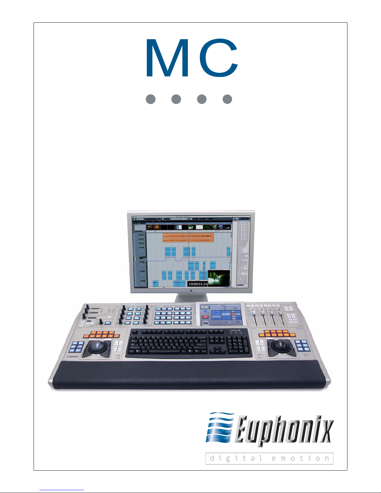
2.1.2 Rear Panel Connections
FOOT
VGA KEYBOARD USB
LANLAN DC INTALKBACK MIC
SWITCH HEADPHONES
VGA and
Keyboard
USB Talkback Mic Output LAN Headphone DC In
Figure 2-1 MC Rear Panel
Foot Switch
DC In: Connect the included DC power supply here. The supply is world-compatible
(accepts 100–240 V, 50/60 Hz) and draws 150 W maximum.
WARNING: Attach power supply to the MC BEFORE plugging into AC power or the
unit may be damaged.
LAN (RJ-45): Network port for connecting to router (Netgear RP614 in standalone
MC setups, or SonicWALL PRO 1260 for System 5-MC). Use CAT5 or better cable.
USB: Connect external storage devices for data backup and software updates. Also
used to connect Ontrak ADU-200 relay interface for multiple workstation setups.
Talkback Mic Output (XLR): Mic-level output for built-in talkback microphone. The
output must be connected to a preamp with 48V phantom power, to obtain line-level
output (phantom power is required because it is a condenser microphone).
Foot Switch (1/4-in Mono): The foot switch mirrors the operation of the Talkback
switch on the MC surface. Connect a standard two-conductor foot switch (like a
MIDI keyboard damper pedal) to the MC Foot Switch jack to toggle Talkback on/
off. (Only on new MCs from March 2007.)
Headphones (1/4-in Stereo): Through connection to front panel headphone connector.
Service VGA and Keyboard (DB15HD, PS2): VGA video and keyboard connection
(for service only).
16
Page 17

Euphonix Media Application Controller Operation Manual Installation and Configuration
2.2 EuCon Software Installation
The EuCon Software installs components that enable bi-directional communication between the MC and workstation. The EuConWS version of the software must be installed
on every workstation used with the MC. The EuConMC version is installed on the MC
when shipped and can be easily upgraded (see page 18).
2.2.1 Uninstalling Previous Versions
The old version of the EuCon software must be uninstalled on the workstation before
upgrading to the new version. Close all applications and follow the procedure for Windows or OS X:
Windows: Choose Start->All Programs->EuCon, and click Uninstall. The EuCon
Uninstaller removes the EuCon software from the workstation.
OS X: Open a Finder window, navigate to the Applications folder, and run the EuCon-
WS Uninstall program to remove the EuCon software from the workstation.
Proceed with installing the new EuCon software. Rebooting the computer before installing the new software is not necessary.
2.2.2 EuCon WS Software Options (Windows only)
The Windows installer offers the following options:
• EuCon Workstation Core: This is the main driver that controls communi-
cation between the MC and workstation. This option cannot be deselected
(it is grayed out and inactive), because it must be installed for the workstation to communicate with the MC.
• Euphonix Studio Monitor Express (SME): This software monitoring ap-
plication interfaces with the MC’s Monitor section. SME can be configured
to receive audio from applications running on the PC or from external sources via physical inputs to your sound card, enabling extensive audio routing,
source selection, and level control from the MC. Those who prefer to use
Nuendo’s Control Room Monitor (similar to SME), may choose not to install SME.
See page 73 for more information on Studio Monitor Express.
• EuCon adapter for Nuendo: This enables EuCon communication between
the MC and Nuendo. Nuendo users must install this component. A license
to enable EuCon within Nuendo (in Nuendo’s Device Setup) is required and
must be authorized on your Syncrosoft USB dongle before you can use Nuendo EuCon with the MC.
17
Page 18

Euphonix Media Application Controller Operation Manual Installation and Configuration
• VST plugin layouts for Nuendo: This option installs .xml files that map
parameters of Nuendo’s VST plugins to the MC’s Soft Knobs and to the
CM408T’s knobs.
• EuCon adapter for Pyramix: Pyramix users must install this component
to enable EuCon control of Pyramix.
2.2.3 Upgrading the EuConMC Software
To upgrade the EuConMC software on the MC:
1. Download the latest version of the EuConMC software from:
www.euphonix.com/support/mc.htm.
NOTE: The EuConMC and the EuConWS software must have the same version and
build or they may not communicate properly. Check the EuConWS version installed on your workstation(s). Download the current version and install it on
all workstations used with the MC if the version/build does not match the EuConMC software you just downloaded.
2. Copy the installation executable you downloaded onto a removable USB drive.
3. On the MC, touch Euphonix Menu->Shutdown, then touch Exit To Operat-
ing System.
This quits the MCApp software.
4. On the MC, click Start->Programs->EuCon->Uninstall.
The EuCon Uninstaller removes the EuConMC software.
NOTE: User sets are not deleted during the uninstall procedure. However, updated
user sets are installed while upgrading the EuCon software. To ensure these
are installed in the default location, backup C:\Program Files\Euphonix\EuCon\User Sets to removable media, then delete the Usersets folder. The new
user sets are NOT installed if the current ones are not first removed.
5. Insert the removable USB drive into the MC’s USB port.
The drive appears in My Computer on the MC desktop.
6. Double-click it to display its contents.
7. Double-click the EuConMC executable file.
The installer program launches. Install the software to the default location
(C:\Program Files\Euphonix\EuCon).
18
Page 19

Euphonix Media Application Controller Operation Manual Installation and Configuration
The MC presents a list of three options to install:
• MCApp, EuCon runtime, etc. - This is the main MC software application.
It is grayed out since it must be installed for the MC to function properly.
• MC PC104 Driver, hardware support, firmware - This installs the actual
hardware driver the EuConMC uses to control the MC surface. DO NOT
UNCHECK THIS OR YOUR MC WILL NOT FUNCTION.
• CM408T Software + Update Server - This insta lls the Firmware Updates
server, which updates the CM408T module firmware. See 2.2.4 Firmware
Update Server (System 5-MC only).
8. Press Next on the remaining dialogs in the Install Wizard.
9. Reboot the MC when the Wizard finishes.
2.2.4 Firmware Update Server (System 5-MC only)
If CM408T Software + Update Server is checked, the Firmware Update Server
launches after the EuConMC installation completes. The CM408T modules will then
prompt to be updated. If they do not, reboot them and they will connect to the Firmware
Update Server. Press the Y key on each CM408T after the update prompt appears. Each
CM408T will apply the update, automatically reboot, and be ready to operate. After all
CM408T modules are updated, quit the Update Server.
19
Page 20
Euphonix Media Application Controller Operation Manual Installation and Configuration
2.3 Configuration
2.3.1 MC Client Software Configuration
Windows
Installing MC Client is discussed in the Installation Guides. Once installed in Windows, MC Client does not need further configuration for applications. It automatically
detects if an application is EuCon-aware and enables EuCon communication. If not, it
enables the MC’s keyboard, trackball, and Soft Keys to control your application as if the
MC were a peripheral directly plugged into your workstation. Since MC Client runs a t
the operating system level, it can control all non-EuCon-aware applications just as your
regular keyboard/mouse combo can (with the useful addition of Soft Key macros).
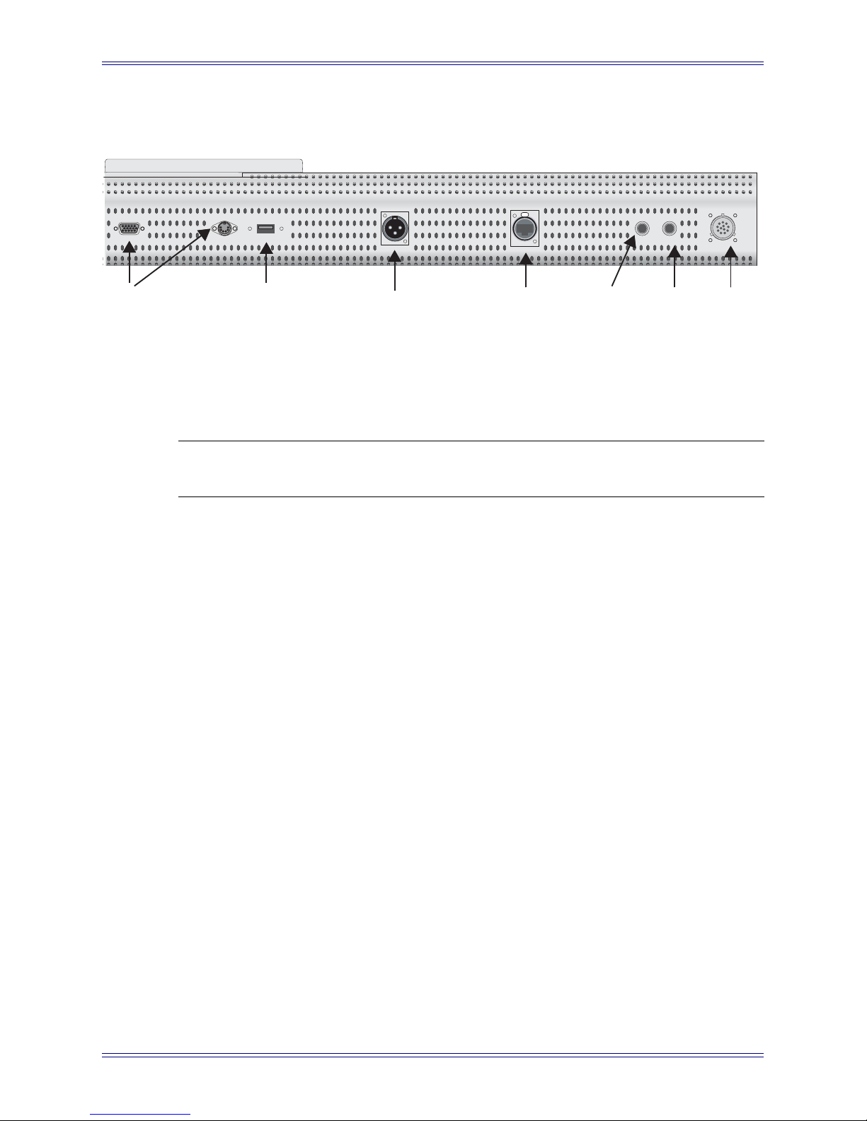
OSX
Since HUI and Mackie Control Universal use MIDI to communicate, they require allocation of MIDI ports by OSX. The OSX EuCon software creates a virtual MIDI driver
with 32 ports, but actual communication with the MC occurs via the faster and more
reliable Ethernet network. HUI and Mackie Control use four MIDI ports per application. Ports are allocated in the Euphonix Preferences Pane (Apple Menu->System
Preferences/EuPrefsPane). Figure 2-2 shows a possible application.
Figure 2-2 Euphonix Preferences pane
20
Page 21

Euphonix Media Application Controller Operation Manual Installation and Configuration
This configuration is only necessary with HUI and Mackie Control applications. EuCon-aware applications communicate automatically with the MC. MC Client enables
the MC’s keyboard, trackball, and Soft Keys to control all non-EuCon-aware applications just as the keyboard and mouse.
2.3.2 MC Client and EuCon Discovery Options
When Windows loads, MC Client and EuConDiscovery services automatically start,
and their icons appear (Euphonix logo combined with orange D for EuConDiscovery
and blue C for MC client) in the system tray, next to the clock.
In OS X, MC Client launches on startup and runs invisibly if the EuPrefsPane is active.
To enable/disable MC Client and EuCon activity, open the EuPrefsPane and press the
Start/Stop button at the bottom of the window. EuCon defaults to active when installed.
In Windows, right-click the EuConDiscovery icon in the system tray for these options:
• Euphonix Network: Lists each installed network card with valid TCP/IP connection. Select the network on which the MC and your workstation will communicate from this list.
• Enable Discovery Network Wide Logging: Toggle this setting on for debugging only.
• Display Discovery Database: Opens list of all EuCon clients on the network.
• Quit: Shuts down the MC Client service.
• About MC Client/EuConDiscovery Service: Displays a dialog box showing
the MC Client/EuConDiscovery copyright notice and software version.
2.3.3 IP Addressing
MC
The Netgear RP614 router included with the standalone MC takes care of all IP addressing, using its internal DHCP server to distribute IP addresses to the MC and your workstation(s). Make sure the router is powered on and connected (with Ethernet cables) to
your MC and workstation(s) for the DHCP server to correctly assign IP addresses.
The WAN port on the Netgear can be connected to a studio LAN, or to an Internet connection, depending on your studio setup. Note that the MC and workstation(s) must be
on the same network subnet for the MC to connect to your workstation(s) properly (connecting them all to the LAN ports on the Netgear automatically does this).
21
Page 22

Euphonix Media Application Controller Operation Manual Installation and Configuration
System 5-MC
The CM408T modules do not allow static IP addressing. Use a DHCP server to autoassign their IP addresses. The SonicWALL PRO 1260 router included in the System 5MC system is set to perform this function by default.
To set up the System 5-MC network, connect the MC and CM408T modules to the
SonicWALL 1260. The SonicWALL 1260 auto-assigns their IP addresses. The MC
can now recognize the CM408T modules. See Modules (System 5-MC Only) on page
26 to configure the MC to control the CM408T modules.
Euphonix ships the SonicWALL 1260 with all default settings unchanged except the
admin username and password, which are both set to Euphonix. The SonicWALL
1260 checks for a DHCP server on the LAN to which it is attached. If a DHCP server
is not found, it enables its own internal DHCP server.
To access the SonicWALL’s web configuration interface:
1. Connect a workstation to one of the 1260’s LAN ports.
2. Set the workstation to obtain an IP address automatically using DHCP.
3. Open a web browser and type 192.168.168.168 (the router’s default IP address)
into the location address field.
4. Log in to the SonicWALL with the username and password Euphonix.
The SonicWALL Setup Wizard then launches to configure the router settings.
Consult the SonicWALL 1260’s manual (included with your System 5-MC or available
at SonicWALL’s website) for more information on router settings. Consult your network administrator to find appropriate settings for your LAN.
22
Page 23
Euphonix Media Application Controller Operation Manual Installation and Configuration
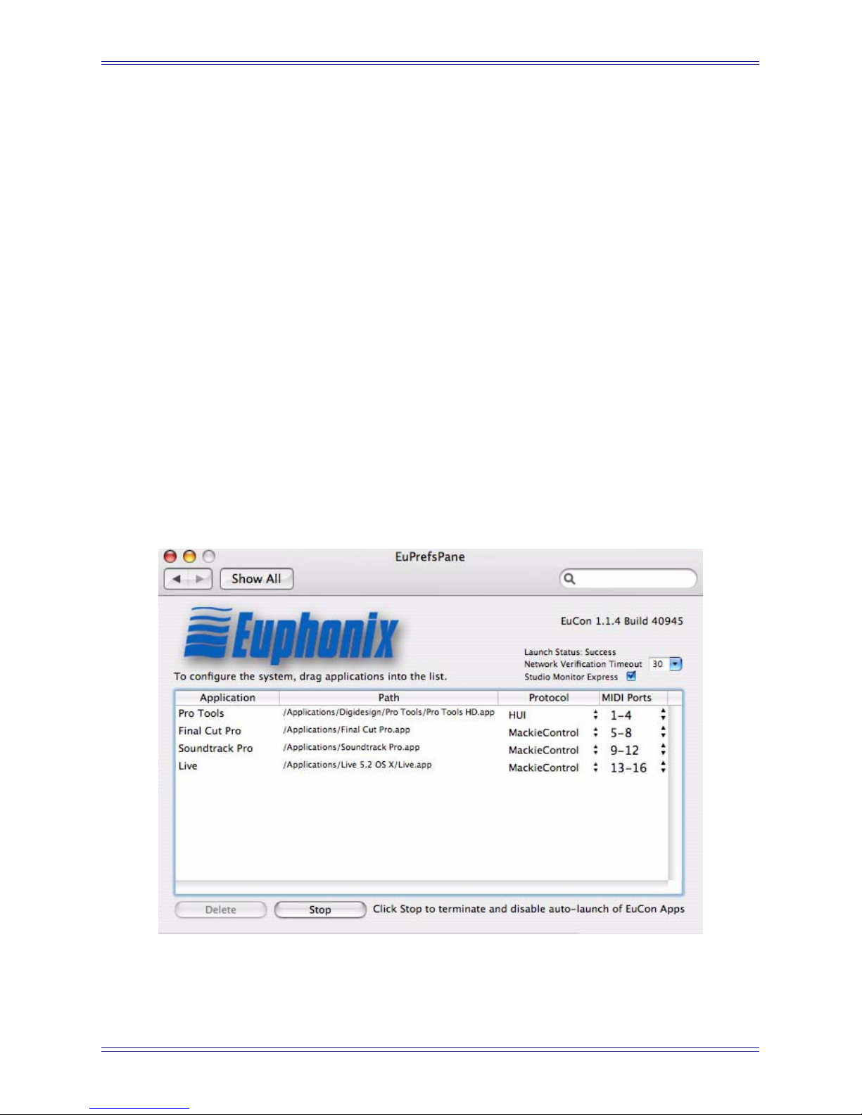
2.3.4 Workstation Control
Workstation
1
3
2
4
Figure 2-3 Workstation keys
The MC can control up to four workstations using the Workstation keys shown in
Figure 2-3.
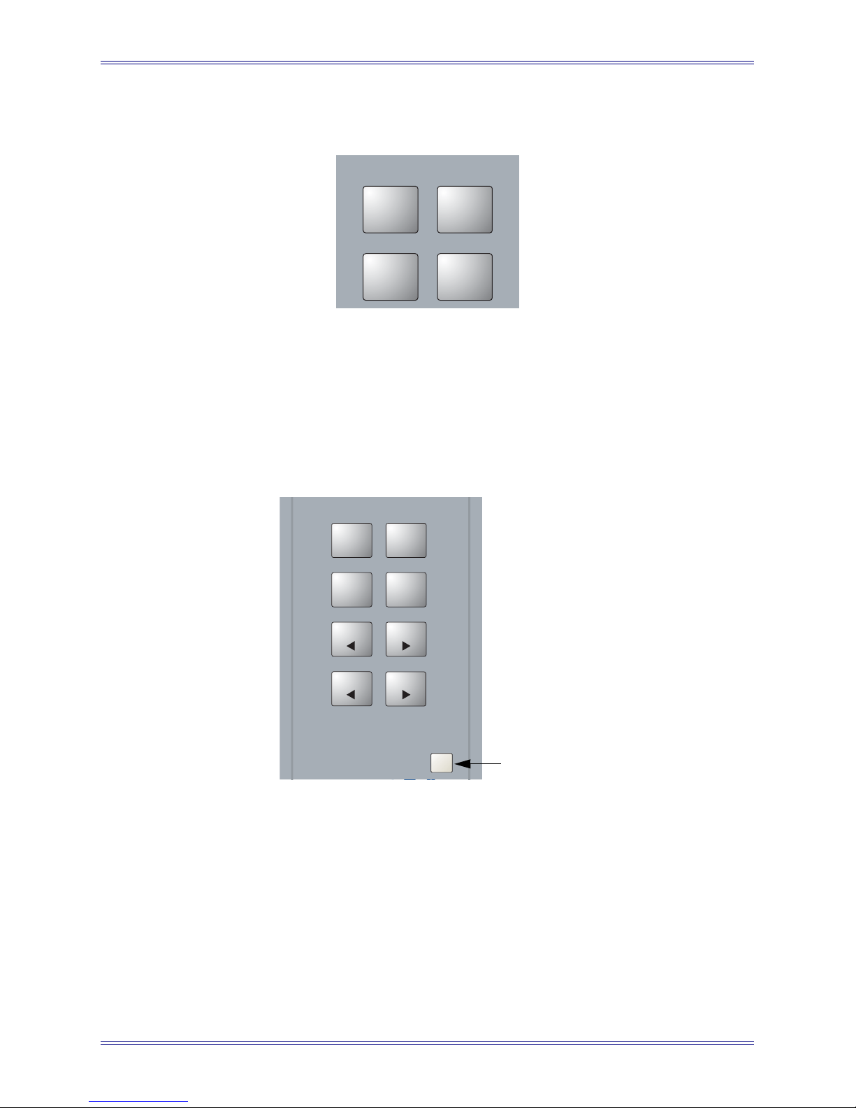
To assign Workstations:
1. Press the Strip Control Setup key on the right side of the MC.
Strip Control
Strip Control
Flip
Layouts
Home
Home
Flip
MC
MC
Nudge
Nudge
Bank
Bank
Nudge
Nudge
Bank
Bank
Setup
Strip Control
Setup
Setup key
Figure 2-4 Strip Control Setup key
23
Page 24
Euphonix Media Application Controller Operation Manual Installation and Configuration
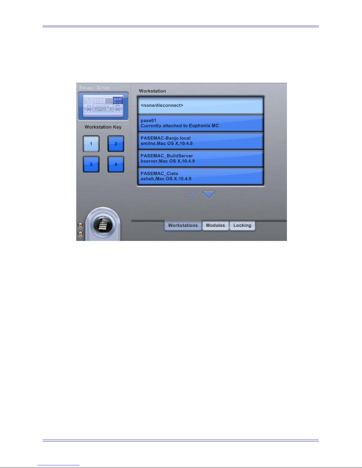
The Touchscreen in Figure 2-5 opens and displays all workstations available on
the network. Each workstation must have MC Client running to be available to
the MC.
Figure 2-5 Workstation Touchscreen
2. Touch the desired Workstation Key on the left of the Touchscreen.
3. Touch the Workstation name in the list to assign it to the selected number.
4. To disconnect the MC from its current workstation, touch the Workstation key
mapped to that workstation, then touch None/Disconnect.
The assignment is relinquished and the MC disconnects from the workstation.
5. To view all Workstations, use the up/down arrows to scroll.
6. Repeat Steps 2 and 3 to assign additional Workstations.
7. Press the Strip Control Setup key again to exit Workstation assignment mode.
8. Press one of the Workstations keys (Figure 2-3) to connect to that Workstation.
24
Page 25
Euphonix Media Application Controller Operation Manual Installation and Configuration
2.3.5 Workstation Binding
Workstation Binding is a feature that retains workstation assignments made in the
Workstations Setup Touchscreen. If you reboot your workstation while connected to
the MC, upon completion of boot-up, pressing the assigned Workstation button reconnects without having to re-assign the workstation. Pressing the previously assigned
Workstation button on the MC re-connects to this workstation without needing to reassign. However, be patient for MC Client to load as it usually takes about 15 seconds
after the computer boots to the Desktop. MC Client’s icon is visible in the Windows
Taskbar when MC Client is launched. There is no equivalent indication on the Mac at
this time. However, if you use SME and have it set to auto-launch (in System Prefs, EuPrefPane) on this Mac, MC Client completes loading shortly after the SME interface
becomes visible. This is particularly useful if you generally use the MC with the same
workstation assignment.
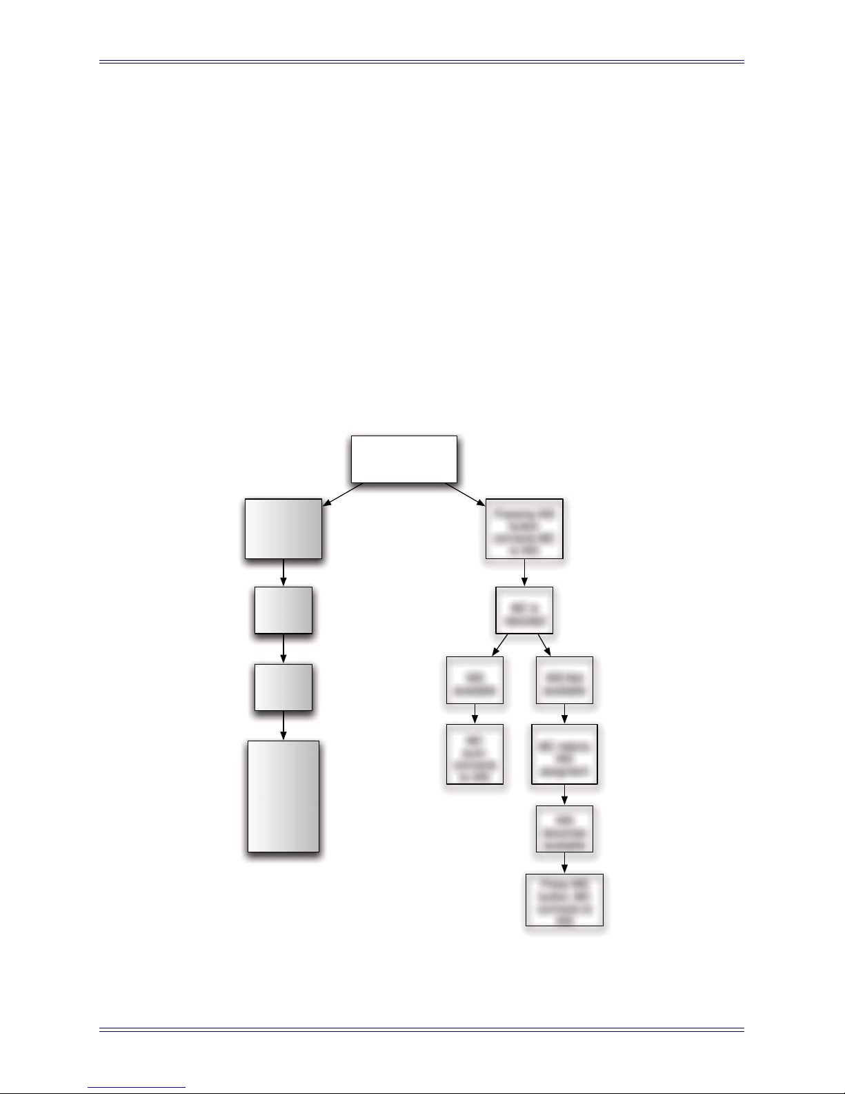
MC Workstation Binding
Pressing WS
button
connects MC
to WS
WS is
rebooted
WS
becomes
available
WS
assignment
retained by
MC -
Pressing WS
button
attaches MC
to WS
User
Assigns
MC to WS
WS
available
MC
auto-
connects
to WS
Pressing WS
button
connects MC
to WS
MC is
rebooted
WS Not
available
MC retains
WS
assigment
WS
becomes
available
Press WS
button, MC
connects to
WS
Figure 2-6 Workstation Binding
25
Page 26
Euphonix Media Application Controller Operation Manual Installation and Configuration
If the MC reboots while connected to a workstation, MCApp re-launches, then the MC
re- connects to the previously assigned workstation without needing to press the Work-
station button.
2.3.6 Visit Workstation
A workstation may be visited by pressing Shift + Workstation 1–4 key. Visiting is a
quick way to deliver keyboard and trackball commands to the visited Workstation without actually performing a EuCon-aware workstation switch. For example, while working in Nuendo, you can quickly switch to a Pro Tools workstation to dismiss an onscreen dialogue or do a quick edit.
Visiting also causes the (optional) Ontrak USB to GPI (for DVI switching) to switch to
the selected Workstation number.
2.3.7 Modules (System 5-MC Only)
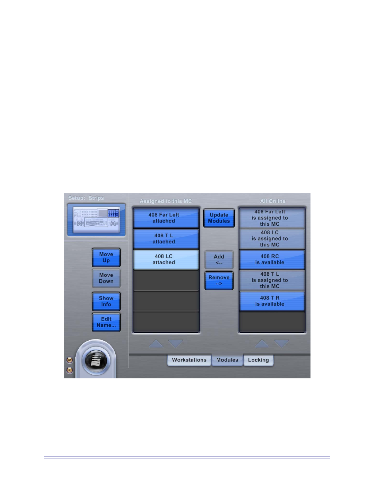
Figure 2-7 Preferences-Modules Touchscreen
This Touchscreen assigns CM408T modules to the MC. All available CM408Ts are
listed on the right under All Online. Currently assigned CM408Ts are listed on the left
under Assigned to this MC. This is the order in which the MC assigns channel strips
to the modules.
26
Page 27

Euphonix Media Application Controller Operation Manual Installation and Configuration
• To assign a module to the MC, touch it in All Online and touch the Add button.
The new CM408T appears under Assigned to this MC.
• To deassign a CM408T from the MC, touch the module in the Assigned to this
MC list and touch the Remove button.
• To change the order of CM408Ts in the Assigned to this MC list, touch the
module and touch the Move Up or Move Down buttons.
• After adding, removing, or moving modules, you must touch the Update Mod-
ules button (flashes when changes have occurred) to apply the settings.
• To display the name, MAC address, IP address, and software version of a
CM408T module, touch it in the Assigned to this MC list and touch the Show
Info button. The information appears on that CM408T’s LCD display.
To name a module, touch it, touch the Edit Name button, and type a name.
27
Page 28

Euphonix Media Application Controller Operation Manual Installation and Configuration
28
Page 29
Euphonix Media Application Controller Operation Manual
Chapter 3: Main Touchscreens
3.1 Main-Tracks
.
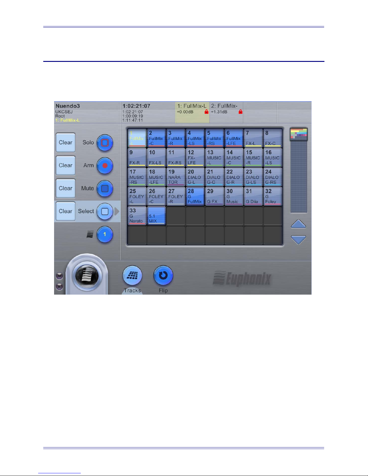
When connected to a EuCon application, this Touchscreen displays the tracks. If the
project has more than 48 tracks, use the scroll bar at the right or the arrow buttons below
it to display additional tracks.
The top-left of the screen displays the following information (top to bottom):
• Application to which the MC is currently connected
• Name of the workstation to which the MC is connected
• Current User Set
• Currently attentioned channel in yellow text
SMPTE time, minutes/seconds, feet/frames, and bar/beat counters are located to the
right of that display.
Figure 3-1 Main-Tracks Touchscreen
29
Page 30

Euphonix Media Application Controller Operation Manual Main Touchscreens
On the top-right, the Touchscreen displays either the four tracks currently assigned to
the four faders, or two tracks currently assigned to the MC’s pair of joysticks.
The left of the Touchscreen displays five mode buttons that apply functions to selected
tracks:
• Solo: Select tracks to solo (see page 37 to learn about solo modes).
• Arm: Arm tracks for recording.
• Mute: Turn tracks on/off.
• Select: Select a track on the MC and in the DAW.
• Wave: Attention a track to the Soft Knobs.
To apply a function, touch its button and then touch track(s) in the grid to apply the
function. Touch selected track(s) again to toggle that function off.
Use the Clear button beside each function to release all tracks from that function. For
example, touch the Clear button next to Solo to unsolo all soloed tracks.
The channel squares in the track grid show their status in several ways:
• Whitish-blue background coloring with yellow text means the channel is selected
• Blue-gray background coloring represents muted tracks.
• A red border around the square means the track is soloed.
• A red dot at the top right of the square means the track is armed for recording
• Colored bars below the text are DAW track colorings in DAWs that offer it
(currently only Nuendo & Logic).
30
Page 31
Euphonix Media Application Controller Operation Manual Main Touchscreens
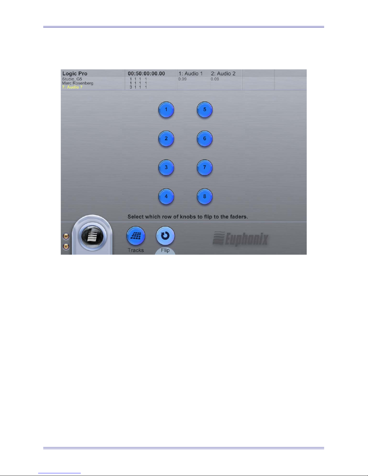
3.2 Main-Flip (System 5-MC Only)
Figure 3-2 Main-Flip Touchscreen
A row of the CM408T module’s knobs can be flipped onto its faders. The parameters
on the row of knobs appear on the faders and the parameters on the faders appear on the
row of knobs. Flip works across the entire console surface.
The Main-Flip Touchscreen shows eight buttons corresponding to the CM408T’s eight
rows of knobs.
1. Touch a number once to flip that row.
The button stays lit while the row is flipped.
2. Touch a highlighted number to flip it back to normal.
The button extinguishes to show the row is no longer flipped.
The Flip buttons intercancel: Touch a new Flip button while a row is flipped to cancel
the first flip and flip the new row.
31
Page 32

Euphonix Media Application Controller Operation Manual Main Touchscreens
3.3 Euphonix Menu
Figure 3-3 Euphonix Menu Icon
Touch the Euphonix Menu icon to display a popup menu with four options pertaining
to configuration and file operations: File, Shutdown, Prefs, and Setup.
3.3.1 M and K Indicators
The M and K indicators correspond to mouse and keyboard, respectively, and show
whether the MC’s keyboard and trackball control the MC (local) or the workstation
(remote):
Orange = mouse and keyboard control MC
Gray = Mouse and keyboard control workstation
On the MC keyboard, pressing Alt+Backslash toggles this control.
3.3.2 File
Touch Euphonix Menu->File to display the File Touchscreen (Figure 11-2). User Sets
and App Sets tabs allow typical File operations on User Sets and Application Sets, respectively. See User and Application Sets on page 89 for more information.
32
Page 33

Euphonix Media Application Controller Operation Manual Main Touchscreens
3.3.3 Shutdown
Figure 3-4 Shutdown Touchscreen
Touching Euphonix Menu->Shutdown is the only proper way to exit MCApp and has
these options:
• Shutdown: Exits MC and operating system.
• Restart: Restarts MC and operating system.
• Exit to Operating System: Exits to Windows XP operating system.
This chapter introduces the MC’s Touchscreen interface and the main Touchscreens
used for normal workflow. The Touchscreen allows touching screen items that you
would normally click with a mouse. The main difference between a touch and conventional interface is that there is no double-touch corresponding to a double-click to
launch or open an item. We will use the word touch (instead of click, select, or press)
to activate, select, or open items. To select an item from a menu, we will use the following convention:
Touch Euphonix Menu->File means select File from the Euphonix Menu.
• When the MC starts, the default Touchscreen is Main-Tracks (Main Touchscreen with Tracks tab selected as shown in Figure 3-1). The Main Touchscreen also has Flip page.
33
Page 34

Euphonix Media Application Controller Operation Manual Main Touchscreens
34
Page 35

Euphonix Media Application Controller Operation Manual
Chapter 4: MC Preference Settings
This chapter discusses the Preference settings in the Euphonix menu that change how
the MC operates.
NOTE: Selected options are colored cyan and deselected options are royal blue.
4.1 General
Figure 4-1 Preferences-General Touchscreen
35
Page 36

Euphonix Media Application Controller Operation Manual MC Preference Settings
This Touchscreen controls six global preferences, each of which may be selected independently (descriptions pertain to the item when selected):
• Workstation tracks knobset changes: Workstation is aware of which knobset
is selected and displays appropriate controls.
• Open plugins on workstation when editing: Plugin windows can be opened
from the surface.
• Close plugins on workstation when finished editing: Window closes when
leaving Knobset.
• Attention most recently selected track: Changes the Soft Knobs to control
the knobset of the most recently selected track. In effect, this links the Wave
key to the Channel Select key.
• Select most recently attentioned track: Selects the track with the knobset
most recently assigned to the Soft Knobs. In effect, this links the Channel Se-
lect key to the Wave key.
• Select channel by touching fader/joystick: Touching a fader assigned to a
specific channel on the MC, CM408T module (System 5-MC only), or joystick
panner, selects that channel in the DAW.
Touch the Wrap-Around Banking button to toggle wrap-around banking on/off.
When enabled, the Bank/Nudge buttons continuously bank through the tracks available, moving from the last track to the first. When disabled, the banking stops at the
highest track (with the Bank Right button) and the lowest track (with the Bank Left
button). This applies to standalone MCs (with a four-fader bank) and System 5-MCs
(with CM408T channel strips).
36
Page 37

Euphonix Media Application Controller Operation Manual MC Preference Settings
4.2 Solo
Figure 4-2 Preferences-Solo Touchscreen
This Touchscreen controls two solo functions: Solo Mode and Solo Switch.
Solo Mode has three settings:
• Solo In Place: Mutes all tracks except solo track.
•AFL: Solo level derived after fader level.
• PFL: Solo level derived before fader level.
In both of the following Solo Switch settings, pressing an active Solo key deactivates
that key:
• Intercancel: Each usage of the Solo switch solos that channel and deactivates
the previous selection.
• Sum: Each usage of the Solo switch solos that channel and leaves other soloed
channels active.
NOTE: Solo Mode and Solo Switch settings are currently only supported by Nuend o.
37
Page 38
Euphonix Media Application Controller Operation Manual MC Preference Settings
4.3 Setup
Touching Euphonix Menu->Preferences->Setup opens the most recently used Setup
Touchscreen.
4.3.1 Devices
NOTE: The Filters buttons and controls are for factory use only. DO NOT modify
these settings unless instructed to do so by a Euphonix representative.
This setting allows the user to swap the mapping of the track wheels (jog rings around
the trackball), enabling the physical left jog wheel to be used as the logical right wheel.
This is useful for left-handed users and to allow two users access to the track wheels
with one person sitting to the left of the MC but operating the right (logical) track
wheel.
To reassign either wheel:
1. Touch Identify Left Wheel or Identify Right Wheel.
The MC displays a dialog requesting movement of the track wheel to remap.
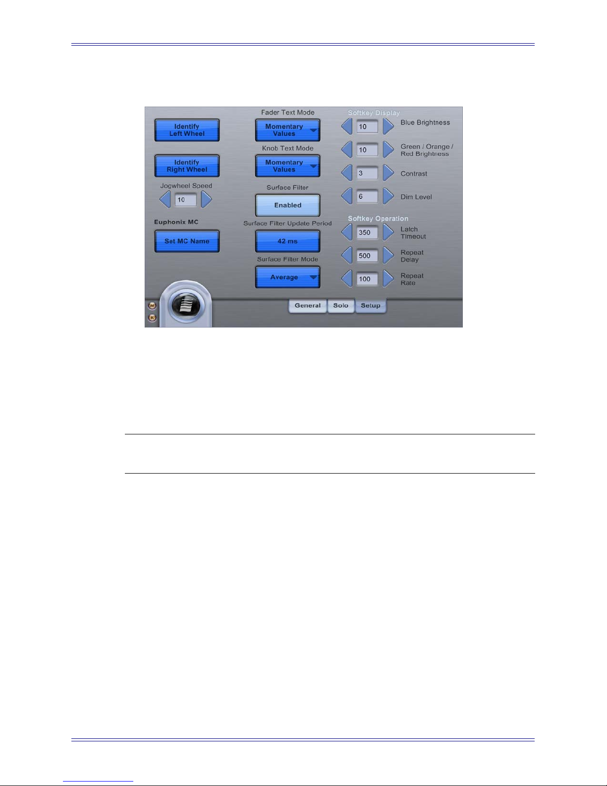
Figure 4-3 Preferences-Setup
2. Move the desired track wheel and touch OK.
The MC now interprets all commands coming from that track wheel as coming from
the Right or Left Wheel you selected.
38
Page 39

Euphonix Media Application Controller Operation Manual MC Preference Settings
4.3.2 Jogwheel Speed
The Jogwheel Speed adjusts the responsiveness of the Jogwheel. A setting of 10 (default) is 100%, or full speed. A setting of 1 is 10%, or slow response.
NOTE: We recommend a setting of 1–3 for Logic Pro.
4.3.3 Surface Filter Update Period
This setting modifies the interval at which the MC sends automation data back and forth
to your workstation(s). The range is 5–250 ms and the default is 42 ms. You will not
need to modify this setting unless your project has extensive automation, in which case
you may need to increase it. Be careful because setting it too low (rate too high) may
deliver incorrect automation.
4.3.4 Set MC Name
The Touchscreen also displays the name of the MC (default is Euphonix MC), and allows changing it. The MC Name is used to distinguish between surfaces in multipleMC configurations. To change the name, touch Set MC Name, type the desired name,
and touch OK.
4.3.5 Fader Text Mode and Knob Text Mode
These settings control how fader and knobset scribble strips on the CM408T modules
behave when displaying text:
• Momentary Value: Displays values as they are changed, then reverts to the
name after a fixed time interval.
• Always Show Names: The name of the control is always displayed.
• Always Show Values: The value of the parameter is always displayed.
The value for fader strips is always the channel level in dB. The knobset value changes
depending on what is assigned to the knobset (EQ, dynamics, plug-in controls, etc.).
4.3.6 Soft Key Display and Operation
This setting controls the text brightness/contrast of the integrated LCDs in the Soft
Keys, and the timing of button latching, repeat delay, and repeat rate.
39
Page 40

Euphonix Media Application Controller Operation Manual MC Preference Settings
To set the brightness of the Soft Keys, use the arrow keys to increase/decrease the illumination (1-10):
• Blue Brightness: Sets the illumination for the blue Soft Keys.
• Green/Orange/Red Brightness: Sets the illumination for the Green/Orange/
Red Soft Keys.
• Contrast: Changes the contrast on all soft keys.
• Dim Level: Sets the illumination for dimmed Soft Keys.
To set the button timing of the Soft Keys, use the arrow keys to increase/decrease the time:
• Latch Timeout: Sets the amount of time (50–500 ms) before a held-down button becomes momentary or non-latching. For example, a Solo button held
down longer than the Latch Timeout setting becomes non-latching and turns
off when released. Buttons held down for a shorter time than this setting behave
normally (i.e., turn on or off depending on their prior state).
• Repeat Delay: Sets the amount of time (250–1000 ms) before a repeatable button starts repeating its command when held down (i.e., Nudge or Zoom).
Repeat Rate: Sets the amount of time (30–400 ms) between the repeated commands
when a repeatable button is held down. The button begins repeating after being held
down for the Repeat Delay setting.
4.4 About
This Touchscreen displays the version of the EuCon software loaded on the MC. The
EuConMC software can be upgraded by downloading the latest version from the Euphonix website (see page 18 for instructions).
Figure 4-4 Preferences-About Touchscreen
40
Page 41

Euphonix Media Application Controller Operation Manual
Chapter 5: Soft Keys
5.1 Banks
Soft Key banks are saved snapshots of all Soft Key commands for a specific MC Soft
Key section. There are three Soft Key sections, each with individual banks: the Soft
Keys section (24 Soft Keys to the left of the Touchscreen), and the Left and Right Edit
sections. The main Soft Keys section has six dedicated bank buttons at the top, and the
two Edit sections each have four bank buttons. However, using the Soft Key Bank Jump
commands, an unlimited number of banks can be created, stored, and recalled. Additionally, a Soft Key in any section can recall banks to both its own section and the other
two Soft Key sections.
A Soft Key can store a sequence of commands (enabling complicated sequences to be
carried out with one keystroke). Soft Keys can transmit four command types:
• EuCon: for in-depth control of EuCon applications (one per Soft Key)
• Key: keystroke sequences to control any application (unlimited per Soft Key)
• Bank: switch banks on one or more of the MC Soft Key sections
• MC: MC-specific commands
Figure 5-1 Soft Keys
The Bank keys display banks 1–6.
41
Page 42

Euphonix Media Application Controller Operation Manual Soft Keys
5.2 Soft Keys Setup
Press the main Soft Keys Setup button (bottom-right of the Soft Keys section) to configure the main Soft Keys. The Right/Left Edit section Soft Keys can be changed by
pressing that section’s Setup button. The Touchscreen changes to show the Soft Keys
setup.
The Commands and Labels tabs of the Soft Keys Setup Touchscreen edit the definitions
and labels of the Soft Keys. Press the Soft Key to modify; it begins flashing. The Commands and Labels tabs display the Soft Key’s currently assigned commands and labels,
which can now be modified.
5.2.1 Commands
Four types of commands can be mapped to a Soft Key:
• Key: macro commands made up of computer keyboard (ASCII) characters
(Figure 5-4).
• EuCon: mapped from MC directly into application using EuCon (Figure 5-6).
• Soft Key Bank Switch: enable navigation to MC Soft Key banks (Figure 5-5).
•MC: MC specific commands are Lay out Recall, Parameter Collect, Parameter
Punch, Read/Write All.
42
Page 43

Euphonix Media Application Controller Operation Manual Soft Keys
Figure 5-2 MC commands
Each Soft Key can contain one EuCon command and unlimited bank switch and key commands chained together in the Soft Key definition. The one EuCon command can be assigned in any slot. The commands assigned to the selected Soft Key are listed by type in
the three slots to the left of the Add button (Figure 5-4). Touch the arrow buttons to the
right of the three slots to move back and forth through the assigned commands. When the
Soft Key is pressed, these commands are executed sequentially from left to right.
43
Page 44

Euphonix Media Application Controller Operation Manual Soft Keys
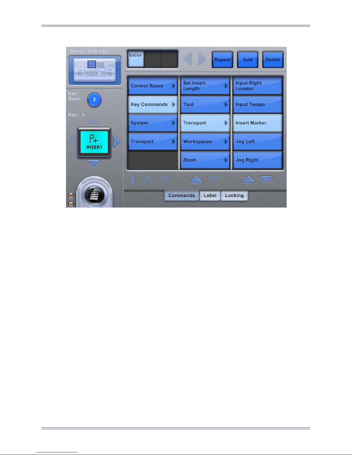
Figure 5-3 Setup-Commands Touchscreen
To assign a command, touch the Add button. A popup menu requests a choice between
adding a Key, EuCon, Soft Bank Key Switch, or MC command. Touch to select the
command type and the screen for that command is displayed (see Figures 5-4, 5-5, and
5-6).
The Repeat button (next to the Add button) sets the Soft Key to be repeatable: When
the key is held down, the MC repeats the Soft Key’s command chain. This is typically
used for zoom and nudge buttons. The repeat rate for the command chain is set in the
Preferences-Soft Keys Touchscreen.
To delete a command, touch the command’s slot in the chain and touch the Delete button. If a command in the middle of the chain is deleted, the remaining commands shift
left to take its place.
44
Page 45
Euphonix Media Application Controller Operation Manual Soft Keys
Figure 5-4 Setup-EuCon Commands Touchscreen
This Touchscreen allows choosing from hierarchical EuCon command menus (the actual contents depend on the EuCon application). To assign a command, touch a category in the left-most menu, and use the submenus to find the desired command. Touching
the command instantly assigns it to the command definition and the Soft Key displays
the default command label.
If there are more than three menu levels, they move to the left as the submenus open. To
get back up to the top of the hierarchy, use the left arrow button below the left-most menu.
45
Page 46
Euphonix Media Application Controller Operation Manual Soft Keys
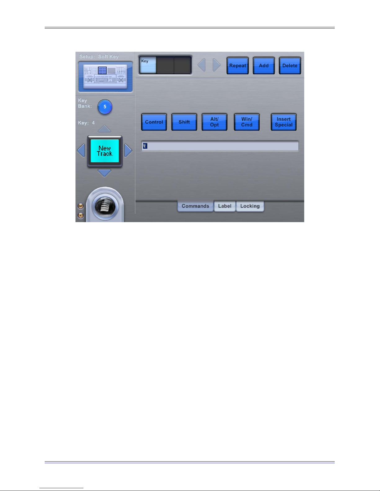
Figure 5-5 Setup-Key Commands Touchscreen
This Touchscreen allows typing a command string that is executed by the MC when the
specified Soft Key is pressed. Touch any of the modifier buttons (Control, Shift, Alt/
Opt, Win/Cmd) to include them as part of the Soft Key’s definition. Multiple modifiers
can be toggled to create complex application shortcuts. For example, to create the command shortcut Ctrl+Alt+Shift+Z, toggle the Ctrl, Alt, and Shift modifiers and type Z
into the command box.
Touch Insert Special to open a popup menu of non-alphanumeric keyboard characters
and commands (i.e., Home, End, Page Up, Page Down, Delete, Backspace, etc.). The command string for those functions is inserted into the command box at the cursor’s location.
Assigning a Key Command function to a Soft Key does not automatically generate
its label. See Label on page 49 to assign an appropriate label to the Soft Key.
46
Page 47
Euphonix Media Application Controller Operation Manual Soft Keys
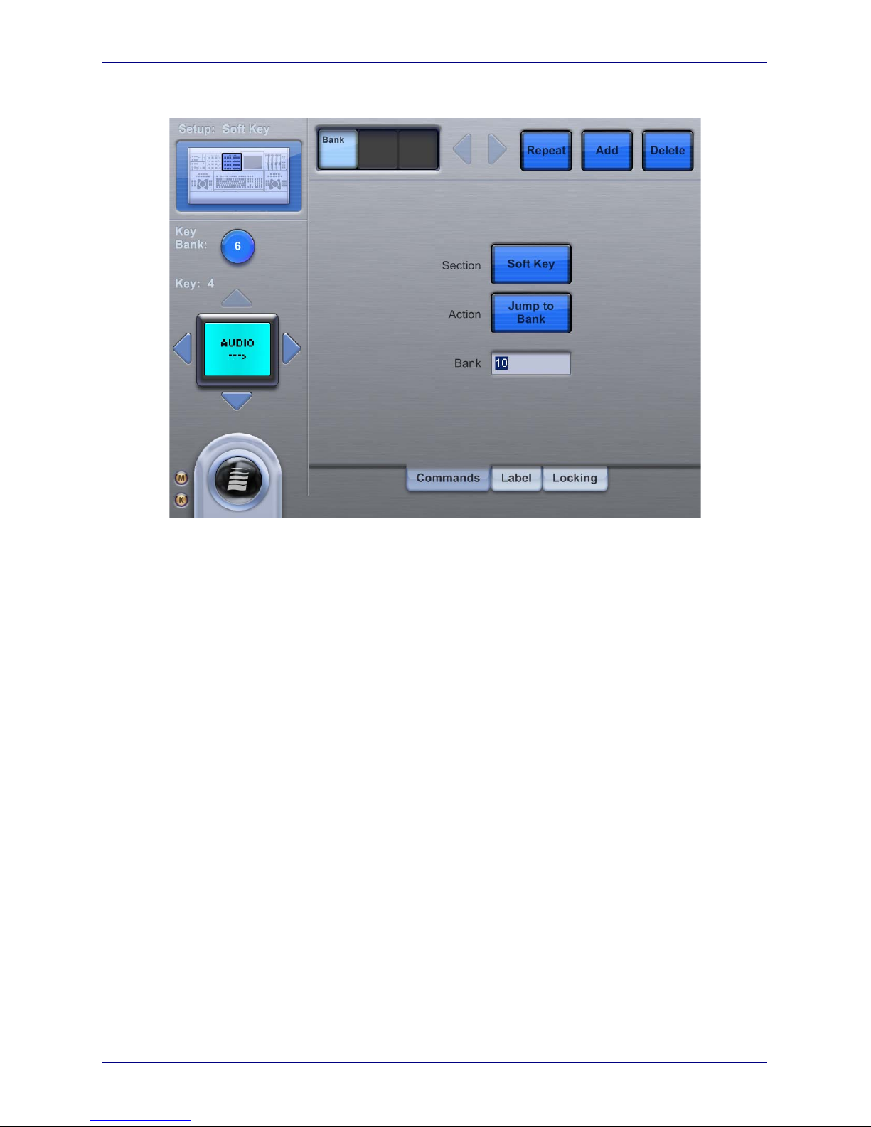
Figure 5-6 Setup-Bank Switch Command s Touc hscreen
This Touchscreen sets a Soft Key to jump to a specific Soft Key bank and determines
which MC Soft Key sections are affected by that bank switch.
Touch the Action button to change the bank switch action. A popup menu selects the
next, previous, or another bank. The current bank is shown to the left above the image
of the Soft Key being edited.
When the Action button is set to Jump To Bank, enter the desired bank number in the
command box below the Action button.
Touch the Section button to choose which section should switch banks. A popup menu
chooses between the Left Edit, Right Edit, or Soft Key sections. This functionality allows the Soft Key’s command to change only one of the MC’s Soft Key sections to another bank (i.e., the Right Edit changes from Transport to Edit controls) while having
no effect on the other Soft Key sections.
Assigning a Bank Jump function to Soft Key does not automatically generate its label.
See Label on page 49 to assign an appropriate label to the Soft Key.
47
Page 48

Euphonix Media Application Controller Operation Manual Soft Keys
5.2.2 Menu Implementation
Allowing a Soft Key to Jump that Soft Key section to another bank provides several
interesting ways to organize Soft Keys. For example, a bank can be created that shows
the application’s pull-down menus (i.e., File, View, Insert, Format, etc.) on the top row.
Figure 5-7 shows an example of a Soft Key menu:
EditFile More
Bank 6 "Menu"
EditFile
New
Open
Close
Bank 7 "File" Bank 8 "Edit"
More EditFile More
Copy
Undo
Redo
Paste
Cut
Figure 5-7
The Nuendo and Pyramix Application Sets use this functionality to put the most important functions on Banks 1–6, with Soft Keys that jump to other banks to display further
options (i.e., the File Menu or the Transport commands).
When implementing this functionality, we recommend creating a Soft Key that jumps
back to one of the top level banks (i.e., the Home key at the bottom-right of every bank
in the Nuendo Application Set). Pressing the Bank 1–6 buttons at the top of the Soft
Keys also navigates back to Banks 1–6.
48
Page 49
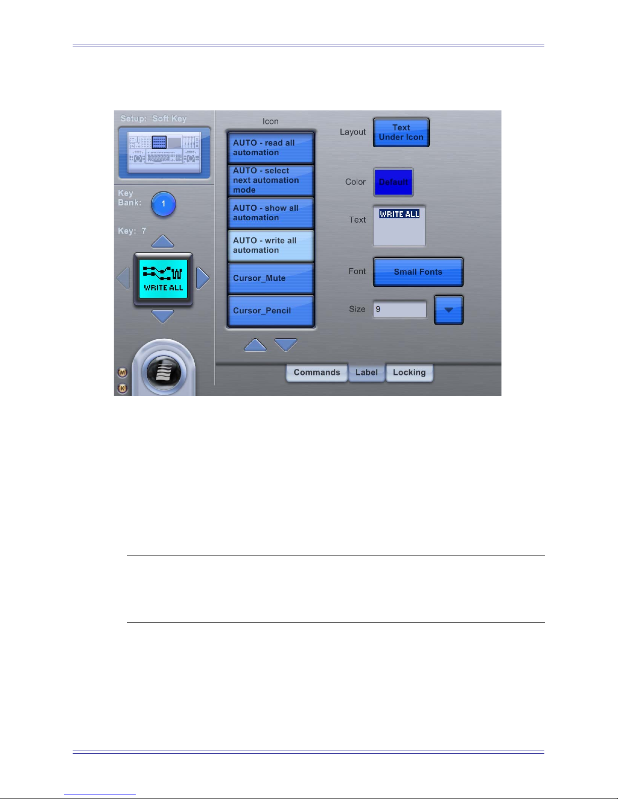
Euphonix Media Application Controller Operation Manual Soft Keys
5.2.3 Label
Figure 5-8 Setup-Label Touchscreen
The Setup-Label Touchscreen allows customizing the appearance of the Soft Keys, including color, font, and size. An icon can be selected from the Icon list. Touch the Layout
button to choose from the popup menu between the following button appearances:
• text only
• text above icon
• text below icon
• icon only
NOTE: When scrolling lists of commands and icons, press and hold Shift while press-
ing Up/Down buttons on the Touchscreen to scroll by page. Press and hold
Ctrl + Shift while pressing Up/Down buttons the Touchscreen to scroll to the
bottom/top of the list.
Touch the Font and Color fields to select the desired entries from their respective popup menus. Only Soft Keys in the Left and Right Edit sections along the top can be colorized. All other Soft Keys are blue only.
Touch the text box to enable editing. The box becomes selected, and the text for the button can be edited using the keyboard.
49
Page 50

Euphonix Media Application Controller Operation Manual Soft Keys
5.2.4 Locking
The Locking tab allows locking any or all of the Soft Key sections to a EuCon application, retaining their commands while the MC is switched to another application or
workstation. The channel strips (or joystick panners) can also be locked in this manner.
This functionality is used to retain control of one application or DAW while using another. For example:
• Locking the Left Edit section to the Nuendo transport controls while working
in Pyramix.
• Using one DAW for playback and another for editing/recording so there is no
need to switch back and forth between workstations in order to control both
DAWs.
• Controlling different applications on the same workstation, such as Pro Tools
with the Left Edit section and Logic Pro with the Right Edit section, all while
editing video in Final Cut Pro.
Figure 5-9 Setup-Locking tab Touchscreen
50
Page 51

Euphonix Media Application Controller Operation Manual Soft Keys
To lock a section:
1. Bring the application into focus in which you intend to lock a section to.
The application is listed at the top-left corner of the MC touchscreen.
2. Press the Setup button of the MC section (Left Edit, Soft Key, or Right Edit) being locked.
3. Press the Strip Control Setup button to select the faders/joystick panners to
lock.
4. Touch the Lock Section button to lock the section to the application on the
MC’s current workstation.
SHORTCUT: To quickly lock a section to an application, put the application in focus,
hold down the Shift key on the MC keyboard, and press the Setup key
of the section to lock. To unlock, repeat this step.
The selected section is shown at the top-left of the Locking tab Touchscreen. If that section is currently locked, the top button of the Locking tab changes from Lock Section
to Unlock Section with a red lock icon to its left (Figure 5-8). The application and
workstation to which the section is locked are listed to the right of the button.
A locked Soft Key section retains its currently assigned commands until it is unlocked
or its individual App Set sections are unlocked.
The fader/joystick section retains its channel control when locked.
The Monitor and Control Room sections continue to monitor the outputs/application
they were locked to.
Press the Unlock All Appset Sections button (appears only when one or more Soft Key
sections are locked) to unlock all currently locked Soft Key sections, without unlocking
the fader/joystick, monitors, or control room sections.
Press Unlock All Sections to unlock all currently locked sections.
NOTE: If any Soft Key section is locked, the Application Set cannot be edited and Soft
Key definitions cannot be changed. All Soft Key (App Set) sections must be
unlocked before changing Soft Key definitions.
51
Page 52

Euphonix Media Application Controller Operation Manual Soft Keys
MC Section Locking
Shift + Left or
Right Edit
Setup Button
Shift + Soft
Knob Setup
Button
Shift + Soft
Keys Setup
Button
Shift + Strip
Control Setup
Button
Press
Shift + Ctrl + any Setup
to "SuperLock"
Locks Left or
Right Edit Section
Locks Soft Knob
Section
Locks Soft Keys
Section
Locks Fader
Section
MC SuperLock
Locks all MC sections & 408s
(except Monitor section)
Locks Assignable Knob
Faders locked to current WS
(touchscreen track display
may display icorrectly
While SuperLock is on,
no individual section
may be unlocked
(except Monitor section)
Shift +
Monitor
Setup Button
When
touchscreen is
locked, only
tracks displayed
on TS can be
selected from TS
Locks Monitor
Section
Figure 5-10 Locking Procedures
52
Layouts Page not
accessable while
SuperLock engaged
Monitor Section is
always independent of
any other section
Page 53

Euphonix Media Application Controller Operation Manual Soft Keys
Superlock
Superlock locks the entire MC and CM408T modules (for S5-MC owners) to one application, except for the Monitor and Control Room sections, which always lock independently of all other sections. This is useful when switching to another application,
without having the MC / System 5-MC constantly switching application sets. For example, you may switch to a database application to look up samples, but want to lock
the MC to your DAW application.
To engage Superlock, focus to the application you wish to lock to, hold down Ctrl +
Shift on the MC keyboard, and press any section’s Setup button (except the Monitor
and Control Room Setup buttons). The entire MC and CM408T modules, except Monitor and Control Room, are now locked to that application.
To disengage Superlock, press Ctrl+Shift+ a Setup button again, or press a Setup button
(showing the locking tab) and touch the Unlock All Sections button on the Touchscreen.
53
Page 54

Euphonix Media Application Controller Operation Manual Soft Keys
54
Page 55

Euphonix Media Application Controller Operation Manual
Chapter 6: Soft Knobs
The MC has nine touch-sensitive knobs with LED display rings to control many parameters. These can also send out HUI data but are more effective when used with EuConaware a p p l i c a t i o n s i n w h i c h t h e y c a n i n t e l l i g e n t l y access functions such as EQ, dynamics, aux sends, or plug-ins.
Left and right keys are available to page within a knobset. The eight knobs operate on
one channel/track within the selected knobset. On the MC, the Soft Key LCD displays
show the knob function and when touched, the knob value. Switches are available for
automation and other knob-related functions.
The Assignable Knob (the bottom-left knob in the Soft Knobs section) can be dynamically assigned to most knob or switch functions in Nuendo and Logic Pro. For ex ample, moving the pointer over a track panner in Nuendo, assigns pan to the MC’s
Assignable Knob. With Logic Pro, clicking on a track panner, assigns that function to
the MC’s Assignable Knob. The Assignable Knob can be locked to a particular function
by pressing the Assignable Knob’s top.
6.1 Knob Cells
The Soft Knobs area is like a Super Channel or Track Inspector to edit a single track. A
channel can be attentioned to the Soft Knobs area for editing, which is different from se-
lecting it. A DAW can select more than one track at once. Attentioning (sometimes called
focusing) is meaningful only for the control surface and is done one track at a time.
55
Page 56
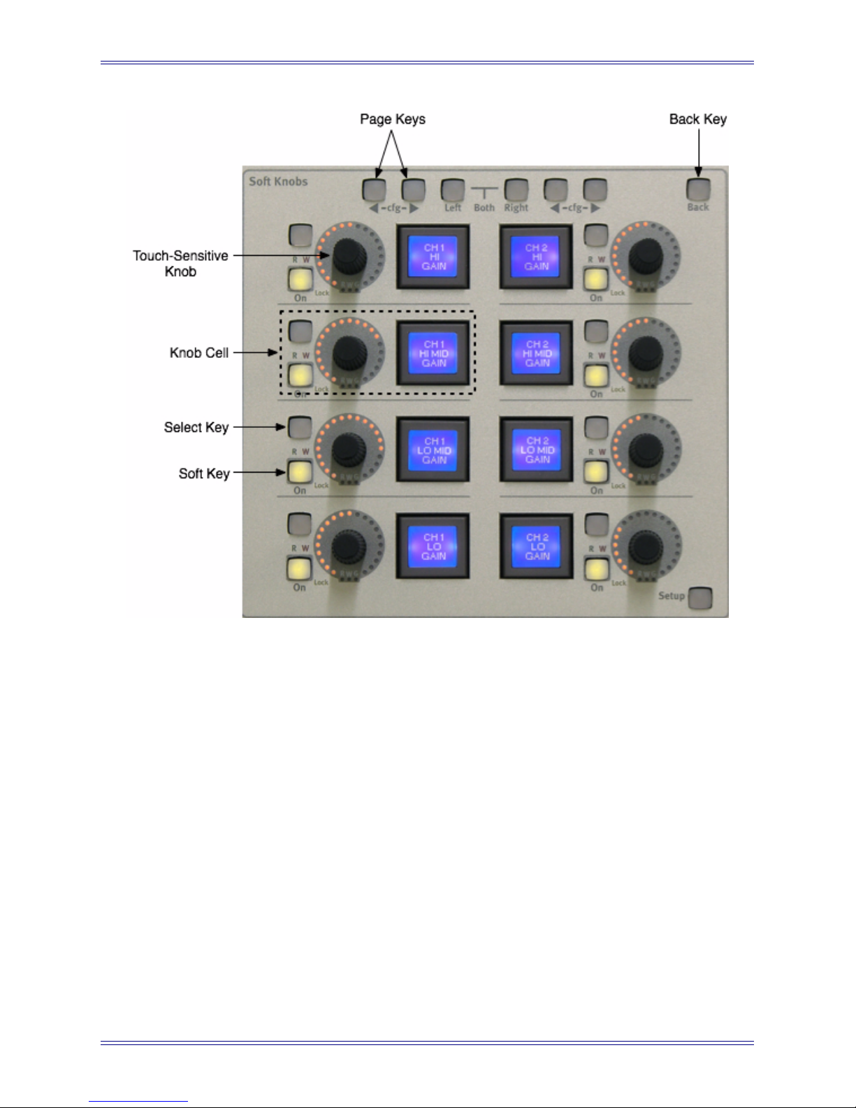
Euphonix Media Application Controller Operation Manual Soft Knobs
Figure 6-1 Knob cell controls in Soft Knobs area
The MC’s bank of Soft Knobs contains eight knob cells, each with a:
• Touch-sensitive knob: controls the parameter shown in the Soft Key’s LCD
• Knob top button (knob press): moves one menu level down the hierarchy
• Soft Key: Displays the current parameter assigned to that knob. Pressing the
Soft Key moves one menu level down the hierarchy (same as Knob top button).
• Select key: depends on specific knob function
• On key: activates/deactivates that parameter
• Lock LED: not currently used
• RW LEDs for On key: not yet implemented
• R and W LEDs: displays automation state of currently selected channel in Nuendo and Logic Pro
• G LED: not yet implemented
• Back key: moves one menu hierarchy up. Not lit if already at top of the menu
structure
56
Page 57

Euphonix Media Application Controller Operation Manual Soft Knobs
In addition, the top of the module has:
• Page Left and Right keys: access additional Soft Knobs pages in the knobset
• Left and Right selector keys: not yet implemented
• Back key: moves one menu hierarchy up.
6.1.1 Knobsets
Each DAW channel function (Aux Send, Inserts, EQ, Pan, etc.) has a knobset associated
with it, and the EuCon software includes knobsets for all supported plugins. A knobset
is comprised of pages of eight parameters each. The MC and CM408T’s knobsets are
identical.
Touch-sensitive Knobs
The knobs are touch-sensitive so the system can detect when the knob is touched,
moved, and released. Touching a knob displays the current parameter’s value on the
Soft Key’s LCD instead of the parameter name. Releasing a knob reverts the display
back to the parameter name (see page 39).
57
Page 58

Euphonix Media Application Controller Operation Manual Soft Knobs
6.2 Assignable Knob
The Assignable Knob can control most knob or switch parameter values in Nuendo or
Logic Pro. In Nuendo, move the cursor over a parameter on the host screen to assign it
to the Assignable Knob. With Logic Pro, you must click the parameter to assign it to
the Assignable Knob. Repeat these functions to assign to other parameters in these
DAWs.
Figure 6-2 Assignable Knob
Press the knob top to lock the current parameter onto the Assignable Knob and light the
Lock LED. The cursor can now be moved to control other DAW parameters while the
Assignable Knob remains in control of the locked parameter. Press the knob top again to
unlock the parameter, which frees up the Assignable Knob to control another parameter.
NOTE: Pyramix does not currently support the Assignable Knob. Apple Logic Pro
users must click the parameter to control first; the Assignable Knob will then
function as described.
6.3 Changing Knobsets
If the Workstation Tracks Knobset Changes preference is set (Preferences-General
touchscreen), the DAW is notified whenever a knobset is selected on the MC or a
CM408T module. This allows the DAW to show the function on the host screen. When
entering a plug-in window, the DAW will open that plugin window if the Open plugins
on entering workstation when editing preference is selected and close it upon leaving
the Insert knobset if the Close plugins on workstation when exiting is selected.
58
Page 59

Euphonix Media Application Controller Operation Manual
Chapter 7: Working with Channels
7.1 Channel Strips
The MC has four channel strips to which workstation tracks can be assigned. The track
names assigned to these strips are displayed in the top-right corner of the Main-Tracks
touchscreen. Workstation tracks can be assigned to the strips using the Channel Select
and Wave strip keys, or using the Layouts-Assign Touchscreen. The System 5-MC has
two motorized joystick panners in place of the four faders.
7.1.1 Solo
When activated, this button solos the assigned channel. Solo preferences are set on the
Preferences-Solo Touchscreen (see page 37).
Figure 7-1 Channel Strips Section
59
Page 60
Euphonix Media Application Controller Operation Manual Working with Channels
7.1.2 On
The On key must be lit (active) to hear the channel. The channel is muted when the
strip’s On button is unlit.
7.1.3 Record
Activate the Record key to enable (arm) a track for recording.
7.1.4 Chan Select Key
Press the Chan Select key to select the channel assigned to that strip. When lit, this
channel is selected in the DAW for editing.
Press the Chan Select key to select a workstation track; it lights when a track is selected.
The workstation’s tracks or mixer window scrolls to show the most recently selected
track.
7.1.5 Select Key
When pressed by itself, the Select key toggles Write mode on/off for the entire track.
LEDs
The green R and red W LEDs are used to denote the automation modes shown in Table
7-1. To set the automation mode, press and hold the Wave key and press the Select key
to select from the popup menu. In Write mode, the red W LED blinks when writing automation and is solid otherwise.
Table 7-1 Automation Modes
Mode R LED (green) W LED (red)
Isolate off off
Read on off
Write off on
Read + Write on on
In Write mode, the red LED blinks when writing automation, and lights solid when the
transport is stopped.
NOTE: The yellow G LED is reserved for future use.
60
Page 61
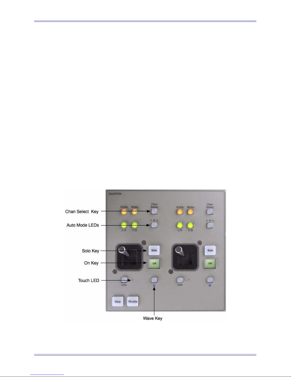
Euphonix Media Application Controller Operation Manual Working with Channels
7.1.6 Wave Key
Press the Wave key to attention a track to the MC Soft Knobs for channel editing. If
Select most recently attentioned track is selected in the Preferences-General Touch-
screen, this will also select the track in the DAW. The Wave key stays lit to indicate it
is the attentioned channel.
Wave + Select
Press the Wave and Select keys simultaneously to display the DAW automation (Read,
Write) mode control on the MC Touchscreen for that track.
Wave + Chan Select
Press the Wave and Chan Select keys simultaneously to assign a track to a strip. This
technique is called Direct Assignment (see page 66).
7.1.7 Fader
When a workstation channel is assigned to a strip, the fader controls the workstation
track’s fader.
7.1.8 Joysticks
Figure 7-2 Joystick Touchscreen
61
Page 62

Euphonix Media Application Controller Operation Manual Working with Channels
Two options are available for the upper-right area of the MC. The standalone MC is
usually fitted with four faders. The System 5-MC includes a pair of joysticks.
The Joysticks can send stereo or surround panning to EuCon-aware applications.
The MC Joysticks section has similar functions as the fader.
7.2 Strip Control Section
Figure 7-3 Strip Control
7.2.1 MC (System 5-MC Only)
The status of the MC key determines whether the Bank and Nudge keys apply to the
CM408T or the MC.
• MC key lit: Bank keys control the MC (default state).
• MC key unlit: Bank keys control the CM408Ts.
7.2.2 Bank Keys
Press the Bank keys to move left or right one bank of four (MC) or eight (CM408T)
strips.
62
Page 63

Euphonix Media Application Controller Operation Manual Working with Channels
7.2.3 Nudge Keys
Press the Nudge keys to move left or right one strip.
NOTE: The Bank and Nudge buttons adhere to the convention that the console is be-
ing “moved” left or right. Therefore, the Bank Left button actually moves the
tracks to the right, and Bank Right moves them to the left.
7.2.4 Home Key
Press the Home key to move track 1 to the left-most strip.
7.2.5 Flip Key (System 5-MC Only)
The Flip key puts an entire row of knobs onto the faders:
1. Press the Flip key and the entire first row of CM408T knobs is flipped to the
faders and volume control flips onto the first row CM408T knobs.
The Flip key lights solid to indicate that a different function is on the faders.
2. Press the Flip key again and the second row of knobs is assigned to the faders.
Pressing Flip eight times cycles through all the knob assignments and back to
no knobs flipped to the faders.
Pressing the Flip key until it is not lit restores the faders to normal operation.
7.2.6 Layouts Key
Layouts are one of the MC’s most powerful features. Layouts allow the assignment of
workstation tracks on the MC/S5MC surface to be stored and recalled. A Layout stores
the mapping of tracks that are Direct Assigned to strips. They do not store mappings of
underlying tracks that are automatically assigned to strips. Press the Layouts key to ac-
cess the Assign and Layout touchscreens.
63
Page 64

Euphonix Media Application Controller Operation Manual Working with Channels
Figure 7-4 Layouts Touchscreen
To create a layout:
1. Press the Layouts button in the Strip Control Setup section on the right of the
MC.
2. Touch the desired number for the layout.
3. Touch the Store button.
4. Touch the Name button to name the layout and touch OK.
To recall or clear a layout:
1. Touch the desired layout’s number.
2. Touch the Recall or Clear button.
The Touch Recall button toggles Touch Recall on/off. When on, layouts are instantly
recalled by touching the layout’s button in the grid. All other layout functions (Store,
Name, Clear) are disabled while Touch Recall is on. First create, name, and store layouts, then activate Touch Recall to have one-button access to them.
64
Page 65

Euphonix Media Application Controller Operation Manual Working with Channels
Touch Recall Mode to select from a popup menu the method to recall track assignments:
• Replace recalls all track assignments from the Layout and replaces the tracks
currently assigned to the channels.
• Overlay recalls only the track assignments stored in the Layout to channel
strips; all other channel strips retain their current track assignments.
Layout Recall from Soft Keys
1. Press Setup in the desired Soft Key section.
2. Add a Soft Key assignment type: MC
The default MC command is Recall Layout 1.
3. To assign Soft Keys to additional stored Layouts, assign subsequent numbers
of stored Layouts from the Layout pull-down.
NOTE: Bank 5 of the default Nuendo Appset is pre-programmed to display Layout Re-
call Soft Keys.
65
Page 66

Euphonix Media Application Controller Operation Manual Working with Channels
7.3 Assigning Tracks to Strips
The MC has four channel strips. The System 5-MC can have a virtually unlimited number of CM408Ts. The MC and CM408T strips can be scrolled independently. The
CM408T strips can have a Main and a Swap track assigned; the CM408T strip’s Swap
key switches between Main and Swap layers.
When the MC connects to a workstation with EuCon DAW software (or Mackie Control Universal/HUI), it automatically populates the channel strips (System 5-MC automatically populates the CM408Ts) with DAW tracks, putting track 1 on channel strip
1 and continuing sequentially. Deleting/adding tracks or changing track order automatically updates the MC/CM408T strips.
7.3.1 Strips and Tracks
Any track can be assigned directly to a strip, similar to System 5’s mapping of channels
to strips. Direct Assigned tracks do not move when the Nudge, Bank, and Home keys
are pressed.
Use the Assign Touchscreen to direct assign tracks to channel strips (the MC’s four
strips, or CM408T module channel strips for System-5 MC).
Figure 7-5 Assign Touchscreen
66
Page 67

Euphonix Media Application Controller Operation Manual Working with Channels
To assign strips:
1. Press the Layouts key in the Strip Control section on the MC (top-right of the
surface) to display the Assign Touchscreen.
2. Touch the tracks in the desired assignment order.
The track numbers appear under Selection Order at the top-left.
3. Touch Insert Blank Strip at the point where a blank strip is desired.
Blank strips appear as asterisks in the selection order.
4. Touch a selected track to remove it from the order.
If the track is in the middle of the selection order, subsequent tracks shift up to
take its place.
5. When finished creating the desired Selection Order, press the Wave key on the
channel strip where the direct assigned tracks should start.
The MC automatically assigns the tracks beginning at that channel strip. Tracks
currently direct assigned to channel strips shift to the right of all the assigned
tracks.
To remove direct assignments, touch the Unassign button. If none of the selected tracks
are currently direct assigned, the Unassign button is gray and inactive.
To direct assign just one strip, press that strip’s Wave and Chan Sel keys simultaneously.
This pops up a list of track names to select on the CM408T’s display or MC Touchscreen. To remove the direct assignment, choose None at the top of the list.
When a track is Direct Assigned to a strip, the underlying tracks, both Main and Swap,
are shifted to the right.
67
Page 68
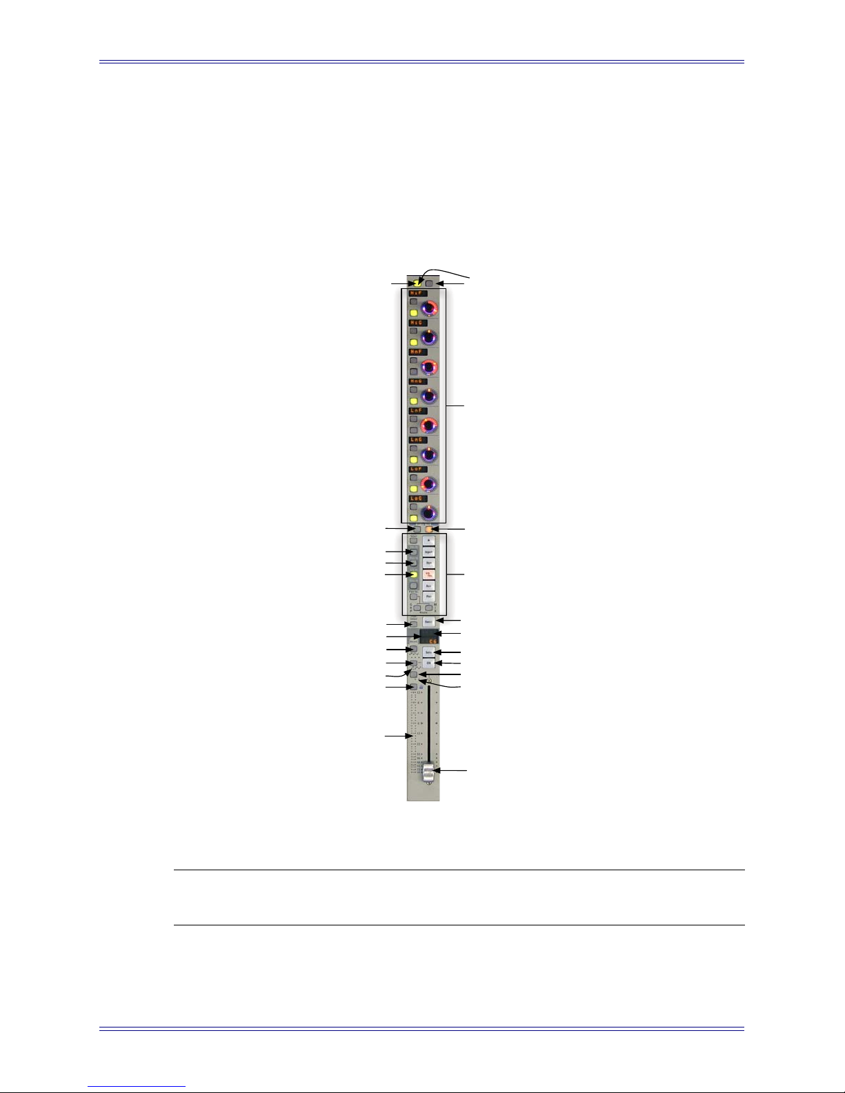
Euphonix Media Application Controller Operation Manual Working with Channels
7.4 CM408T Channel Strips (System 5-MC only)
The CM408T channel strip is similar to the strip on the standalone MC with faders, but
also have a four-character LED scribble strip display, and a high-resolution TFT display
to show additional channel information, metering, pan, and EQ graphs.
The CM408T channel strip has the following attributes:
All Key
Page L
Insert Master
Dyn Master
EQ Master
Chan Select Key
Main Layer Display
Record Key
Input Monitor
Auto Mode LEDs
Wave Key
Back Buttons
Soft Knobs
Page R
Knobsets
Swap Key
Swap Layer Display
Solo Key
On Key
Auto Write Toggle
Touch LED
NOTE: Press and hold the strip’s left-top button then press the right button to navigate
back (up) one level.
See Channel Strips on page 59 for an explanation of these features.
Signal Meter
Fader
Figure 7-6 CM408T channel strip
68
Page 69
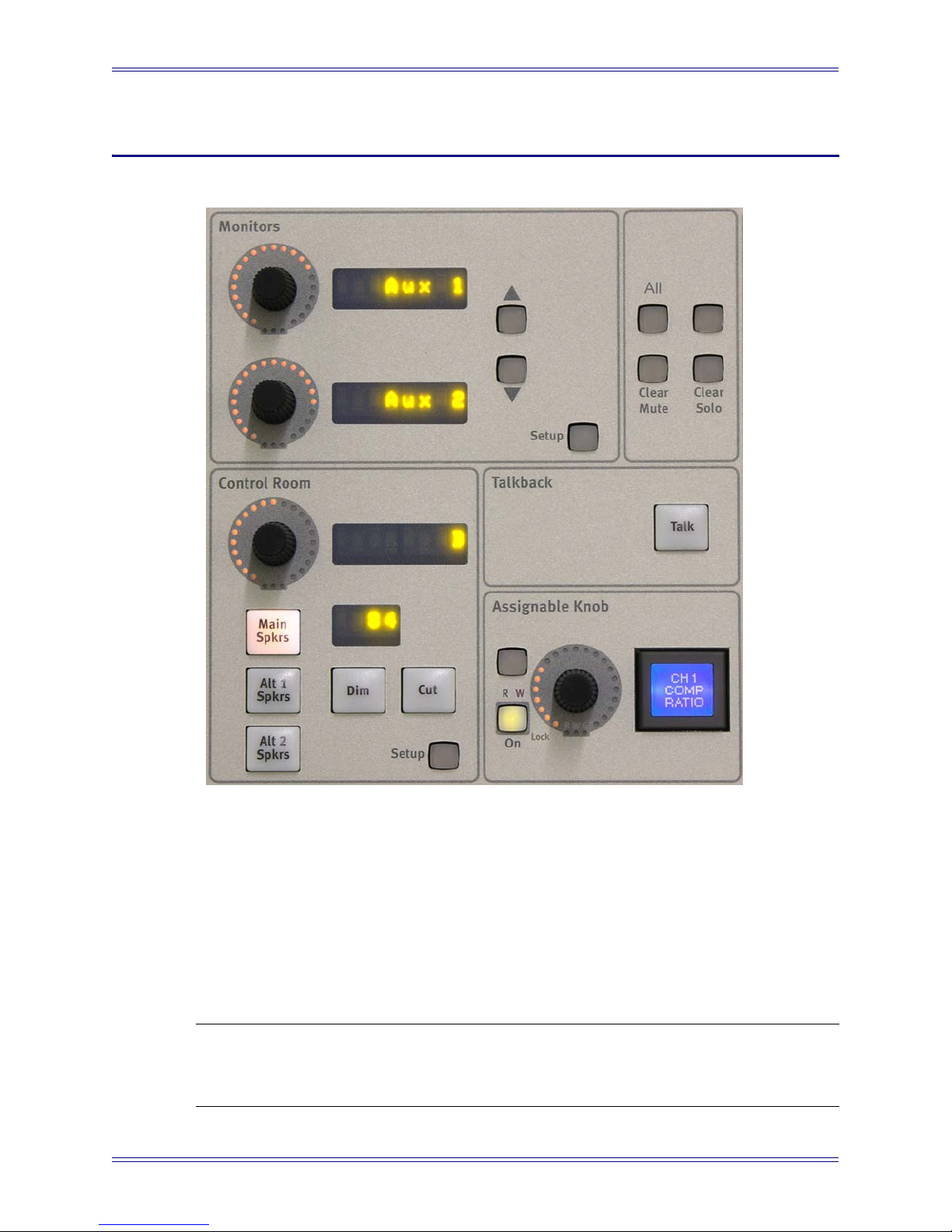
Euphonix Media Application Controller Operation Manual
Chapter 8: Monitors and Control Room
Figure 8-1 Monitors, Control Room, and Talkback Sections
The Monitors and Control Room sections of the MC surface allow for controlling various monitoring setups. The MC does not process or route audio: it interfaces with a EuCon-aware application’s monitoring section or with the Euphonix Studio Monitor
Express (SME) application (see Chapter 9: Studio Monitor Express (Windows)). Monitoring controls for Pyramix and Nuendo are described on page 108 and page 93, respectively. This chapter explains the MC’s integration of these controls with SME for
use with generic DAW applications.
NOTE: The Monitor section may be locked to your preferred application so monitor
control is not interrupted by focusing to another workstation or application. See
page 50 to lock the monitor section.
69
Page 70

Euphonix Media Application Controller Operation Manual Monitors and Control Room
8.1 Control Room
The touch-sensitive knob controls the overall Control Room volume. The level is
shown in the LED display to the right of the knob. The source is displayed in the lower
LED display.
Figure 8-2 Control Room Section
Main Spkrs, Alt 1 Spkrs, Alt 2 Spkrs
These buttons switch the main Control Room feed between three sets of speakers:
• Main Spkrs:Up to 5.1 channels of Control Room Monitor Out
• Alt1 Spkrs: Up to 5.1 channels of Control Room Monitor Out
• Alt2 Spkrs: Stereo Control Room Out
The selected source is displayed in the LCD to the right of the knob. Use SME to configure the Main, Alt1, and Alt2 audio sources.
Dim and Cut
The Dim key reduces the Control Room monitor level by a user-specified amount.
While Dim is engaged, moving of the Control Room knob adjusts the dim amount. Dim
amount can also be adjusted in SME.
The Cut key turns off the Control Room output.
Control Room Setup
This key opens the Control Room Setup Touchscreen. This chooses the source for the
Control Room feed, selects a folddown matrix, solos speakers, and sets the dim and
talkback mic levels. See MC Control Room and Monitor Setup on page 95.
70
Page 71

Euphonix Media Application Controller Operation Manual Monitors and Control Room
8.2 Monitors
Figure 8-3 Monitors Section
The Monitors section of the MC surface can control up to two monitor outputs per page,
labeled Monitor A and B in SME. Audio sources for Monitor A and B are configured
in SME’s Main tab or the MC’s Touchscreen (see page 74).
Touch-sensitive Knobs: These knobs control the level (displayed in the LED display
to the right of the knob) of their respective monitor outputs.
Up/Down Arrow Buttons: These buttons switch the knobs from controlling the first
two outputs to controlling the second two outputs.
Setup: This key opens the Monitor Setup Touchscreen. Toggle selected Monitor A and
B audio source(s) from the list displayed on the Touchscreen.
The top-right unmarked key is currently not implemented.
71
Page 72

Euphonix Media Application Controller Operation Manual Monitors and Control Room
8.3 Clear and All Keys
Figure 8-4 Clear and All Keys
The Clear Solo key turns off the solo on all DAW track s even if several solo modes are
supported (i.e., AFL, PFL, SIP).
The Clear Mute key unmutes all DAW tracks.
The All key is a System 5-MC only feature that, when lit, causes knobset selection on
one CM408T channel strip to be applied to all CM408T channel strips.This key functions in Nuendo and Pyramix only.
The right unmarked key is currently not implemented.
8.4 Talkback
The Talkback button dims the Control Room output (according to the Dim Level) and
activates the Talkback Mic channels assigned in SME (the Talkback Mic is active when
the button is held down). Pressing the button momentarily latches it, and holding it
down longer than the Latch Timeout setting (see Chapter 5: Soft Keys) makes it a momentary button; it releases when the button is released.
NOTE: The Foot Switch jack can toggle Talkback on/off (see page 16).
72
Page 73

Euphonix Media Application Controller Operation Manual
Chapter 9: Studio Monitor Express (Windows)
Studio Monitor Express (SME) is a powerful and flexible audio monitoring software
application that runs on your workstation or a dedicated computer and controls the
routing between applications, external inputs, and ASIO hardware. SME outputs are
routed to the audio I/O hardware and can be controlled from the MC’s Monitors secton. SME can be considered a software version of a mixing console’s master and
comms section.
SME provides a professional surround sound monitor mixer with up to two 5.1-speaker
outputs and an additional stereo output each with level, cut, and talkback controls. SME
can also be used to listen to external inputs without any other application open.
SME can be installed (optional) during the workstation EuCon software installation
(see page 17).
73
Page 74

Euphonix Media Application Controller Operation Manual Studio Monitor Express (Windows)
9.1 Main
Figure 9-1 Main Tab
Main tab controls:
• mapping of Sources created in the Sources tab (page 75) to Control Room,
Monitor A and Monitor B, also selectable from the MC Monitor section’s
Touchscreen.
• monitor level sliders, control levels to Control Room, Monitor A, Monitor B,
and correlates to the two Monitors knobs in the MC’s Monitors section.
• Cut: Cuts the Control Room signal completely; correlates to MC’s Cut button.
• Dim: Select the checkbox to attenuate the signal to the Dim Level set in the
Config tab (page 80).
• Fix: Select the checkbox to set the signal to the Fixed Level set on the Config
tab; correlates to MC’s Dim button (page 80).
• Phase: Select the checkbox to reverse the phase of the left channel (no surface
control for this parameter).
Only sections created in the Sources tab appear in the Source boxes (Figure 9-1). To
route a Source to a specific Monitor section, select it in the Source box for the desired
monitor output.
When the workstation and MC are connected, the changes made in this tab are reflected
in the Monitor and Control Room section on the surface, and vice versa.
74
Page 75

Euphonix Media Application Controller Operation Manual Studio Monitor Express (Windows)
9.2 Sources
Figure 9-2 Sources Tab
The Sources tab is used to create sources to SME’s mixer inputs. To create a source,
select the Format (Mono, Stereo, or 5.1), select the Start Channel, type a name into
the Name field, and click the Create button. SME creates the input monitoring section
and adds it to the list of sections on the Main tab; it is now available for monitoring.
To create a section called CD Player: Select Stereo from the Format, select 1 as the
Start Channel, type CD Player in the Name field, and press the Create button. This
creates a stereo monitoring section for SME mixer input channels 1 and 2. The inputs
to that section are defined in the Hardware I/P Patch tab (page 78), where a hardware
input can be patched to each SME I/P.
75
Page 76
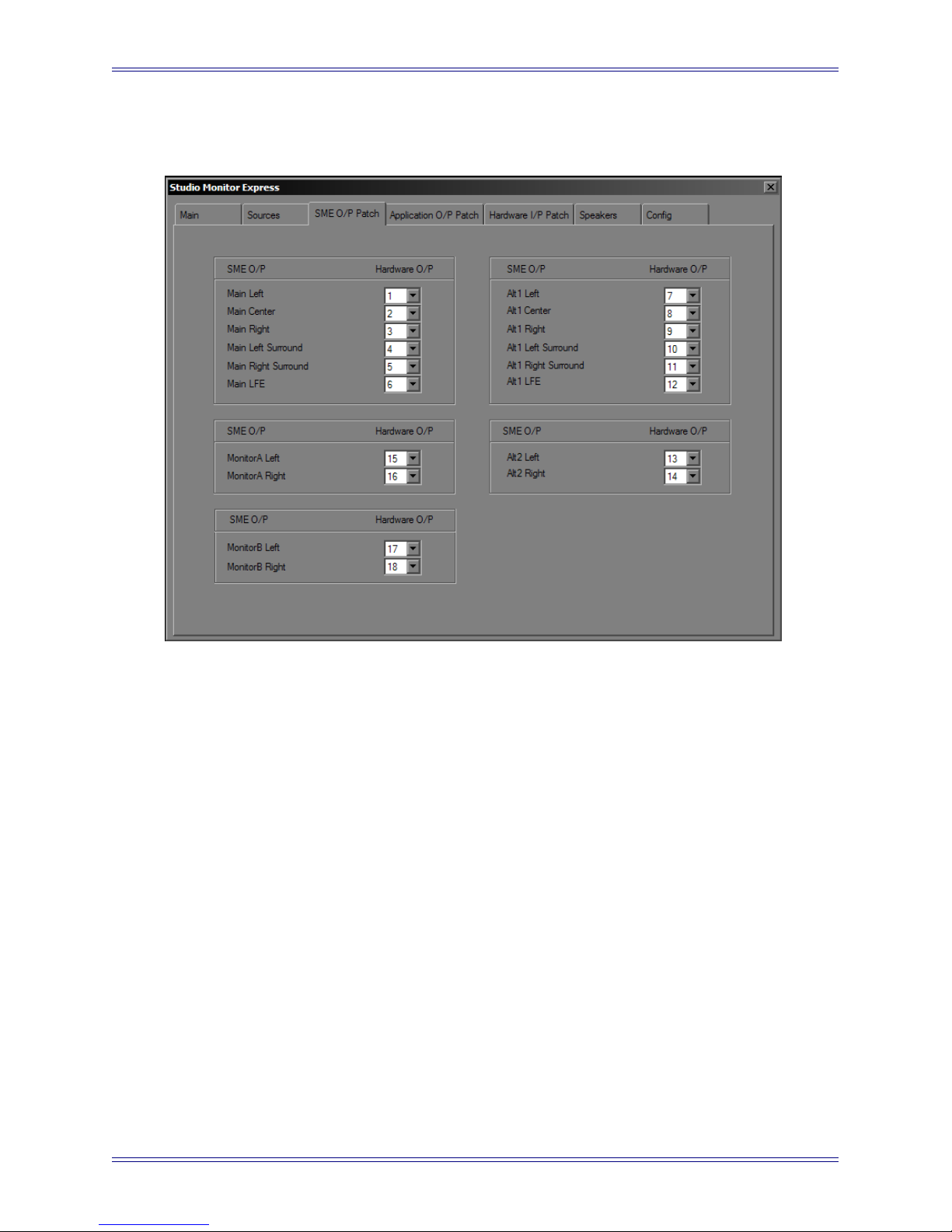
Euphonix Media Application Controller Operation Manual Studio Monitor Express (Windows)
9.3 SME O/P Patch
Figure 9-3 SME O/P Patch Tab
The SME O/P Patch tab sets the physical output channels from each of SME’s monitors
sections to the audio I/O hardware. Select the desired outputs from the Hardware O/P
drop-down menus.
76
Page 77
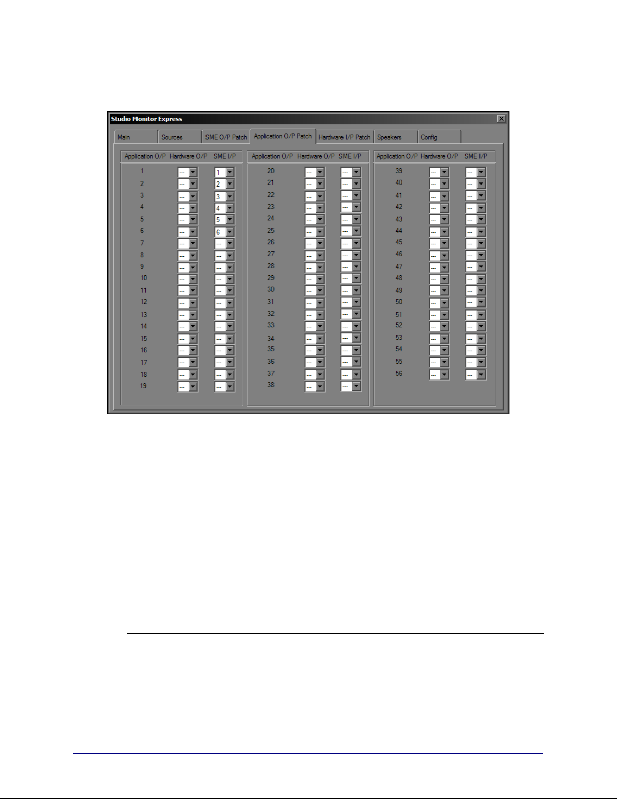
Euphonix Media Application Controller Operation Manual Studio Monitor Express (Windows)
9.4 Application O/P Patch
Figure 9-4 Application O/P Patch Tab
The Application O/P Patch tab routes the application outputs (i.e. Nuendo) to the audio
I/O hardware outputs and/or SME Inputs.
The Hardware O/P drop-down allows applications using the SME ASIO driver to
route signal directly to the physical outputs (bypassing SME).
The SME I/P drop-down allows applications using the SME ASIO driver to route signal into SME’s mixer. It is possible to select both a Hardware output and SME Input
simultaneously, creating a mult.
NOTE: Only outputs enabled in the Config tab (page 80) are available from the Hard-
ware O/P and SME I/P drop-down menus.
If the main outputs from your DAW application are Hardware O/Ps 1–6, they would
typically be sent to SME O/Ps 1–6. However, it is possible to route the speaker outs to
a different order (i.e., SMPTE surround format) than your monitors: For example, output 3 (which your DAW expects is Right Front but you wish to be Center) can be routed
to the actual output you use for Center.
77
Page 78
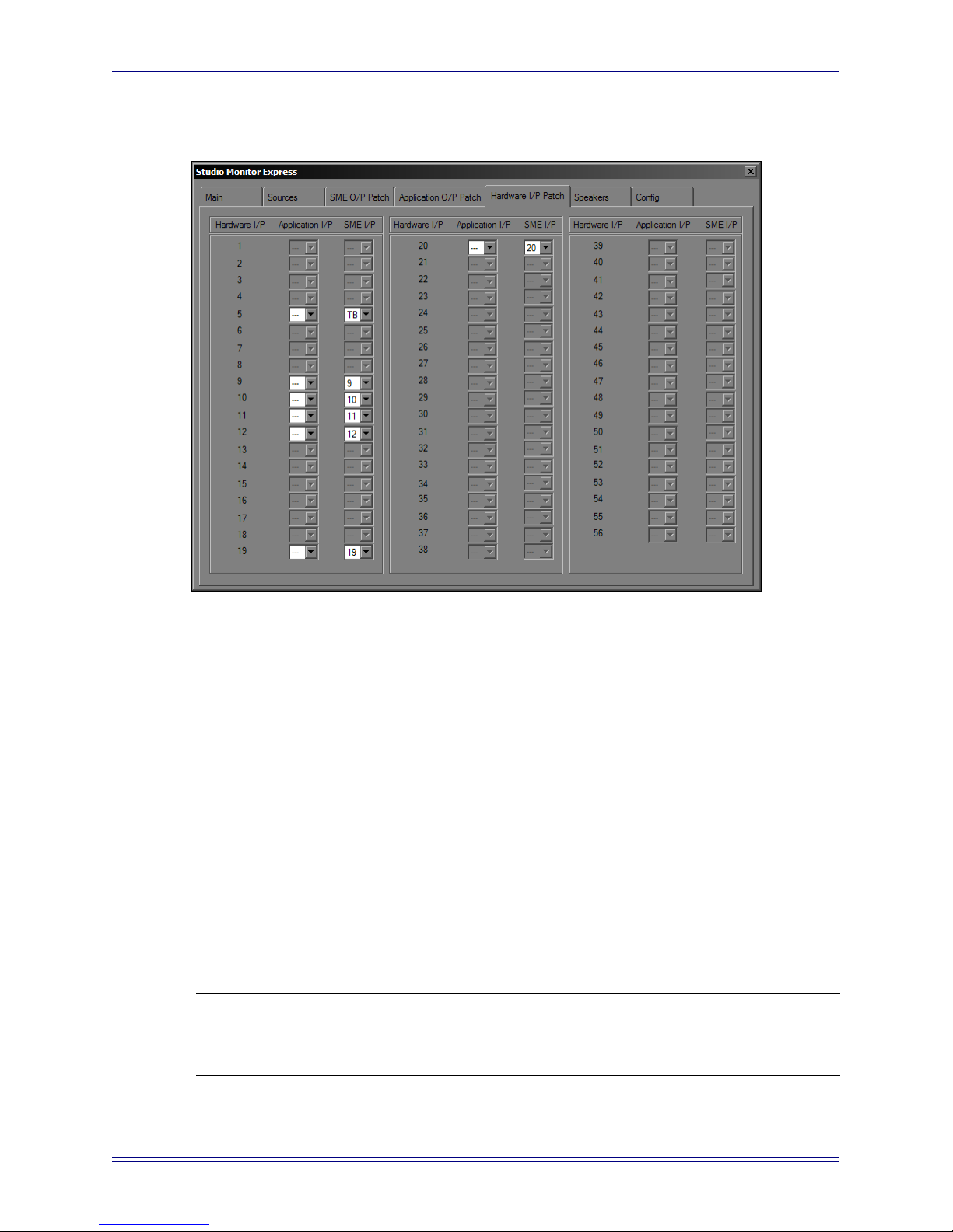
Euphonix Media Application Controller Operation Manual Studio Monitor Express (Windows)
9.5 Hardware I/P Patch
Figure 9-5 Hardware I/P Patch Tab
The Hardware I/P Patch tab routes audio from the hardware inputs (Hardware I/P) on
your workstation’s sound card to the Application I/P and/or inputs of SME’s mixer inputs (SME I/P).
To pass audio from a physical input to an application, the hardware inputs (Hardware
I/P) must be patched to Application I/P inputs. We recommend a one-to-one patch to
make it easier to track the mapping between physical inputs and channel inputs in your
DAW. However, it is possible to re-route a hardware input to a different EuIn input. For
th
example, if the kick drum is on the 24
physical input and you wish it to appear to your
DAW that it’s on the 1st input: select 1 from the Hardware I/P 24’s Application I/P
drop-down menu.
Refer to the CD Player example on page 75: If your CD player is routed to hardware
inputs 40 and 41, select 1 and 2 from the Hardware I/P 40 and 41’s SME I/P dropdown menus respectively. This routes the CD player to Mixer inputs 1 and 2, which
were set to a stereo monitoring section on page 75.
NOTE: Only outputs enabled in the Config tab (page 80) are available fro m the Appli-
cation I/P and SME I/P drop-down menus. SME minimizes its CPU resources
if you enable only the inputs you plan to use.
78
Page 79
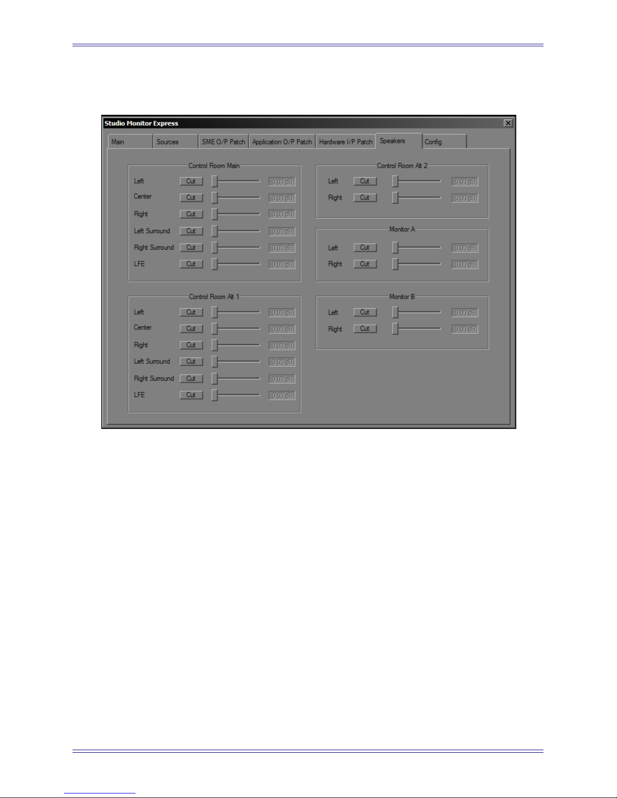
Euphonix Media Application Controller Operation Manual Studio Monitor Express (Windows)
9.6 Speakers
Figure 9-6 Speakers Tab
The Speakers tab allows attenuating and muting monitor section output levels. Drag the
faders to adjust the level indicated in the field to the right of the fader. Click the Cut
button to mute the output.
Each monitoring section has its own controls:
Control Room: Main, Alt1, Alt2
Monitors: A and B
79
Page 80
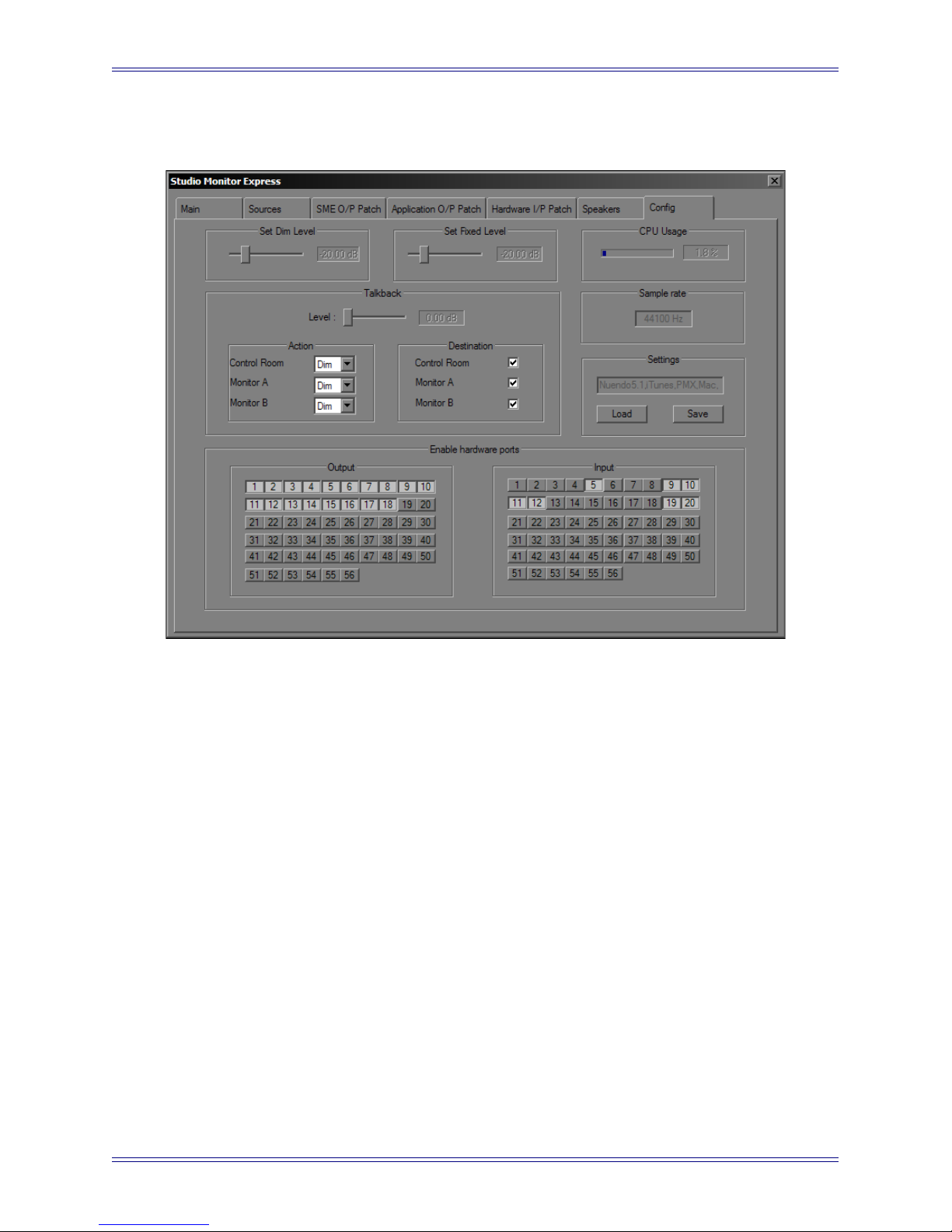
Euphonix Media Application Controller Operation Manual Studio Monitor Express (Windows)
9.7 Config
Figure 9-7 Config Tab
The Config tab displays the current sample rate, sets various levels, and enables the
hardware inputs and outputs that patch to sources and destinations.
Set Dim Level: This sets the attenuation amount (in dB) for the program signal when
using the talkback function.
Set Fixed Level: This sets the fixed output level, which is selectable in the Main tab for
the Control Room output. This is useful for setups that have been calibrated to a specific
db level and must maintain a fixed output level.
CPU Usage: This meter shows SME’s CPU usage.
Sample Rate: This shows the current sample rate to which SME is locked. This is only
an indicator since the sample rate is determined by your sound card’s settings.
Settings: This enables saving the current settings or loading previous settings, to quick-
ly switch between different SME configurations.
Enable hardware ports: This allows explicitly enabling or disabling each SME port.
This limits the ASIO stream’s inputs and outputs monitored by SME, thus minimizing
traffic on the PCI bus to only those ports necessary for the current setup. Only ports enabled here are available for routing to or from on the other tabs.
80
Page 81

Euphonix Media Application Controller Operation Manual Studio Monitor Express (Windows)
9.8 Configuring SME Talkback
To configure SME Talkback:
1. Connect the MC Talkback Mic to a microphone preamp with 48V phantom
power (required).
2. Connect the mic preamp’s output to any input on your sound card.
3. In the Config tab, enable the input that you connected the preamp to on your
sound card.
4. In the Config tab Talkback section, Set the desired Level, Destination and
Action.
5. In the Hardware I/P Patch tab, route the Hardware Input to SME I/P “TB”,
which appears at the bottom of the pull-down list (after channel 32).
81
Page 82

Euphonix Media Application Controller Operation Manual Studio Monitor Express (Windows)
82
Page 83

Euphonix Media Application Controller Operation Manual
Chapter 10: Studio Monitor Express (Mac)
Studio Monitor Express (SME) is a powerful and flexible audio monitoring software
application that runs on your workstation or a dedicated computer and controls the
routing between applications, external inputs, and Core Audio compliant hardware.
SME outputs are routed to the audio I/O hardware and can be controlled from the
MC’s Monitors section. SME can be considered a software version of a mixing console’s master and comms section.
SME provides a professional surround sound monitor mixer with up to two 5.1-speaker
outputs and an additional stereo output each with level, cut, and talkback controls. SME
can also be used to listen to external inputs without any other application open.
SME can be installed (optional) during the workstation EuCon software installation and
includes a Euphonix Monitor Core Audio Driver for integration with applications you
wish to use with SME on the Macintosh (see page 17).
10.1 Main
Figure 10-1 Main Tab
83
Page 84

Euphonix Media Application Controller Operation Manual Studio Monitor Express (Mac)
Main tab controls:
• mapping of Sources created in the Sources tab (page 85) to Control Room,
Monitor A and Monitor B, also selectable from the MC Monitor section’s
Touchscreen.
• monitor level sliders, control levels to Control Room, Monitor A, Monitor B,
and correlates to the two Monitors knobs in the MC’s Monitors section.
• Cut: Select this button to cut the signal completely.
• Dim: Select this checkbox to attenuate the signal to the Dim Level set in the
Config tab (page 88).
• Fix: Select this checkbox to set the signal to the Fixed Level set on the Config
tab; correlates to MC’s Dim button (page 88).
• Phase: Select this checkbox to reverse the phase of the left channel (no surface
control for this parameter)
Only sections created in the Sources tab appear in the Source boxes (Figure 10-1). To
route a Source to a specific Monitor section, select it in the Source box for the desired
monitor output. Sources can also be selected from the MC Monitors section Setup
Touchscreen.
When the workstation and MC are connected, the changes made in this tab are reflected
in the Monitor and Control Room section on the surface, and vice versa.
84
Page 85
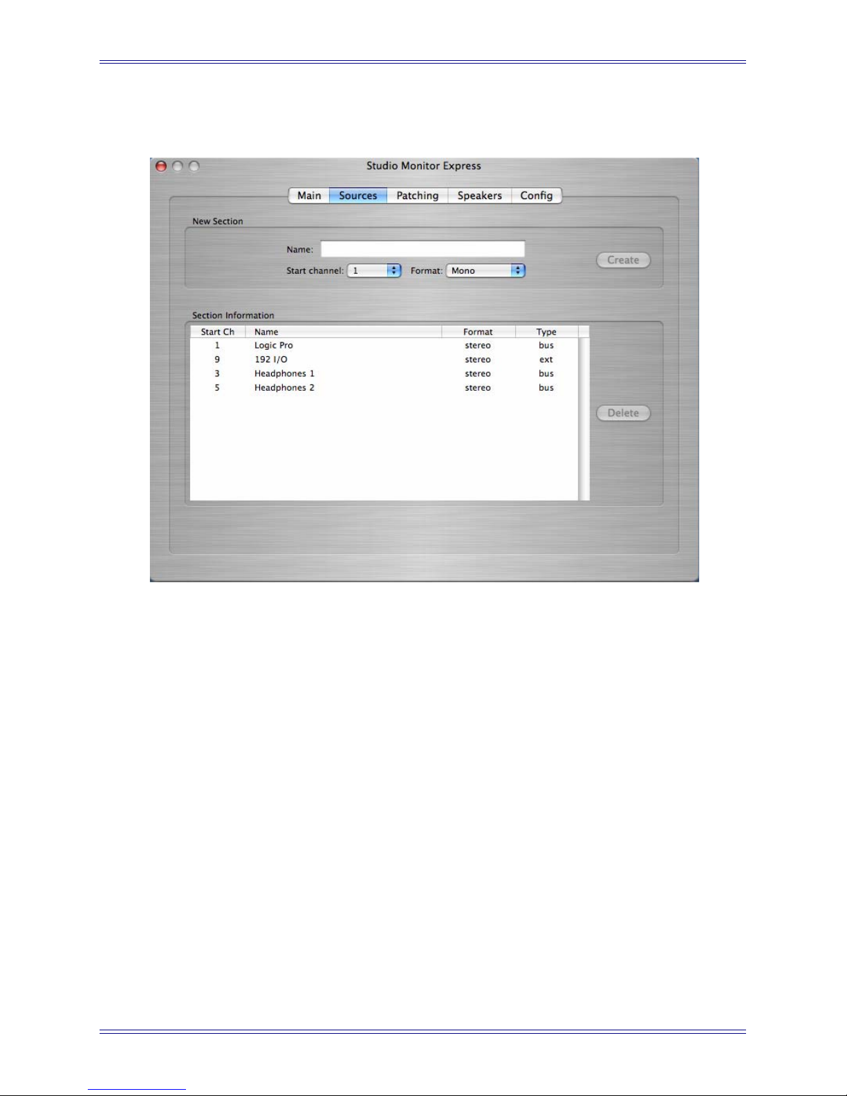
Euphonix Media Application Controller Operation Manual Studio Monitor Express (Mac)
10.2 Sources
Figure 10-2 Sources Tab
The Sources tab creates sources to SME’s mixer inputs. To create a source, select the
Format (Mono, Stereo, or 5.1), select the Start Channel, type a name into the Name
field, and click the Create button. SME creates the input monitoring section and adds
it to the list of sections on the Main tab; it is now available for monitoring. Channels
1–6 are used f o r intern a l b u s s e s f r o m the app l i c a t i o n u s i n g t he Studi o M o n i t o r C o r e
Audio driver. Channels 9–16 are reserved for external inputs, physical inputs to the audio I/O (i.e. an external CD player connected to the sound card inputs).
To route stereo audio from an application running on the Macintosh into SME, select
Euphonix Monitor as the application’s Core Audio output driver. In the SME Sources
tab, create a stereo source, name it (Logic, Nuendo, etc.), and set the start channel to 1.
This creates a stereo monitoring source for SME mixer input channels 1 and 2. Enable
the source in SME Main tab or from the MC Monitors section setup Touchscreen.
To create a source for a stereo external input (i.e., a CD Player): Select Stereo from the
Format, select 9 as the Start Channel, type CD Player in the Name field, and press
the Create button. This creates a stereo source for SME mixer external input channels
9 and 10. The inputs to that source are defined in the Patch tab (page 86).
85
Page 86

Euphonix Media Application Controller Operation Manual Studio Monitor Express (Mac)
10.3 Patching
Figure 10-3 Patching Tab
The Patching tab routes the SME inputs from applications running on the Macintosh
that are using the Euphonix Monitor Core Audio driver, external inputs to the workstation’s sound card, and the SME outputs.
The Input section (left) has eight selectable inputs from application outputs, and eight
selectable inputs from the audio device (sound card) installed in your workstation. Each
application used with SME must be set to use the Euphonix Monitor Core Audio driver.
WARNING: Only one application may use the Euphonix Monitor Core Audio driver at
a time.
The Output section (right) sets the sound card outputs to which the SME’s Main, Alt 1,
Alt 2, Monitor A, and Monitor B outputs are routed. For example, to change a 5.1 output from L-C-R-Ls-Rs-LFE to L-R-Ls-Rs-C-LFE, you can change the output routing
instead of physically repatching the outputs to your monitors.
86
Page 87
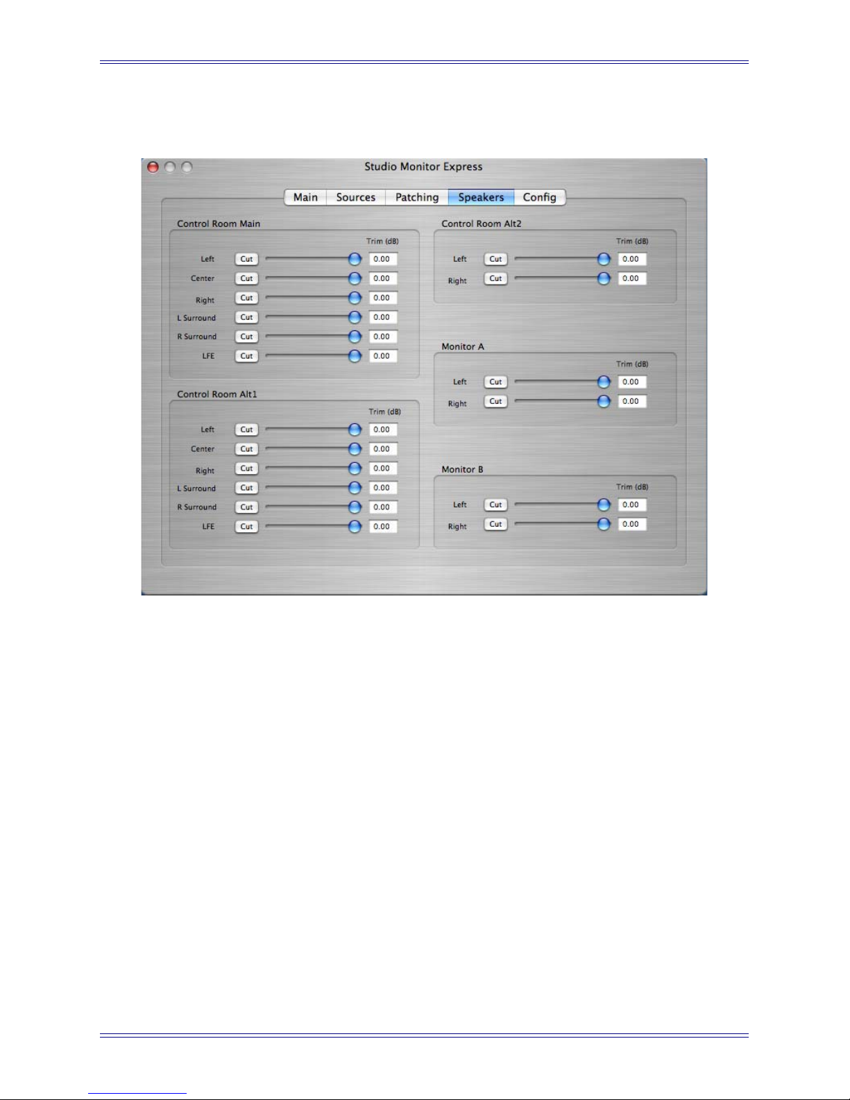
Euphonix Media Application Controller Operation Manual Studio Monitor Express (Mac)
10.4 Speakers
Figure 10-4 Speakers Tab
The Speakers tab calibrates and mutes output levels. Drag the faders to adjust the level
indicated in the field to the right of the fader. Click the Cut button to mute the output.
Each monitoring section has its own controls:
Control Room: Main, Alt1, Alt2
Monitors: A and B
87
Page 88
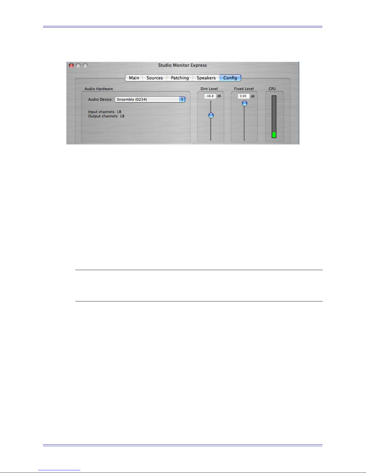
Euphonix Media Application Controller Operation Manual Studio Monitor Express (Mac)
10.5 Config
Figure 10-5 Config Tab
The Config tab displays the currently selected Core Audio device driver, Dim and
Fixed output levels, and a CPU meter.
Audio Device: This pull-down menu selects the Core Audio driver for the sound card
to use with SME.
Set Dim Level: Sets the attenuation amount (in dB) for the program signal when press-
ing the MC monitors section Dim button.
Set Fixed Level: Sets the fixed output level for the Control Room output. This is useful
for setups sending the output of the DAW to a separate mixer or router that has its own
level controls, instead of controlling the output level from SME.
CPU Usage: Shows SME’s CPU usage.
NOTE: When the output driver is changed, patching is reset to default settings with no
external or output patches enabled. Patches must be reassigned in the Patching tab.
10.6 Talkback Setup
1. Connect the MC’s Talkback Mic to your audio interface.
2. Enable 48V phantom power for the Talkback Mic (required).
3. In the SME Sources Tab, create and name a Source Talkback (required).
4. In the Main Tab, enable Talkback for each section requiring Talkback routing
(Main, Mon A, Mon B).
5. In SME Main Tab, press the Talkback button to enable Talkback.
6. Press the MC’s Talkback button to engage Talkback (follows latching/mo-
mentary logic defined in Soft Keys Setup on page 42).
7. Connect a standard footswitch to the MC’s rear panel Footswitch jack to toggle Talkback on/off remotely.
88
Page 89

Euphonix Media Application Controller Operation Manual
Chapter 11: DAW Integration
One of the MC’s most exciting abilities is dynamically detecting application and workstation switching: all controls on the surface switch to match the active application on
the selected workstation. The MC automatically detects not only the application but
also if it is EuCon-aware, HUI, Mackie Control, or a generic application, and sets the
control mode accordingly. The MC’s surface setups can be saved to the MC’s hard
drive as Usersets, which contain Application Sets for each application.
See page 23 to assign workstations to the Workstation keys.
11.1 User and Application Sets
To view the MC User Sets or Application Sets, touch Euphonix Menu->File. The File
Menu opens, displaying the User and App Sets tabs.
A User Set is a folder that contains any number of Application Sets. Usersets can be
saved and loaded from disk, and may contain variations of the various App Sets.
For example, a user may choose to create different User Sets for specific types of Nuendo projects: Recording, Editing, Mixing, Mastering, etc. The relevant controls for
each type of project are available on the MC’s surface.
User Sets can also help if the MC is used by more than one operator by recalling setups
for each.
Upon startup, the MC loads the Root User Set, which is the default User Set containing
App Sets for many of the most widely used applications. You can modify and save the
Root User Set or create a totally new User Set.
An App Set is an .xml file that contains metadata defining Soft Keys assignments for
each application, and also includes text, icon, and Soft Key color. The MC ships with
App Sets for many applications, but new App Sets can be easily created for applications
without one. Switching applications causes the MC to automatically load the focused
application’s App Set (if it exists).
Because of the flexibility of the MC’s Soft Key programming, Application Sets can also
be very useful for sending key commands to generic applications (i.e., Adobe Photoshop, Acid, SoundForge).
An Application Set stores all functions specific to an application:
• All banks of 16 Edit Control Left Keys
• All banks of 16 Edit Control Right Keys
• All banks of 24 Soft Keys
89
Page 90

Euphonix Media Application Controller Operation Manual DAW Integration
Left Edit Banks Right Edit Banks
A Default Application Set is provided and used in case there is no App Set for the application currently in focus.
11.1.1 User Sets
Knobsets
Figure 11-1 Content of an Application Set
Soft Key Banks
Keyboard/Trackballs
Faders/Joystick
Panners
User Sets store a collection of Application Sets. The Touchscreen in Figure 11-2 displays a file hierarchy in the columns from left to right. For example, the Root User Set
is in the MCUser folder in the UserSets folder. Each column scrolls with the up/down
arrows below the column.
Figure 11-2 File-User Sets Touchscreen
90
Page 91

Euphonix Media Application Controller Operation Manual DAW Integration
Copy: Copies the selected Userset into the Clipboard.
Paste: Pastes the Userset in the Clipboard and creates another with the same name ap-
pended by Copy (exactly like the Windows Explorer or MacOS Finder).
Reveal Opened: Displays the Userset currently open and in use.
Restore Root: Restores the Root Userset, the default Userset that ships with the MC.
The Root Userset contains Appsets for the most widely used applications. Use this
function only to restore the MC Root Userset back to factory settings; you will lose
changes in a modified Root Userset.
11.1.2 Application Sets
An Application Set stores the Soft Key assignments on the MC surface. An unlimited
number of Application Sets can be created, one for each of the applications you use.
Figure 11-3 File-App Sets Touchscreen
91
Page 92

Euphonix Media Application Controller Operation Manual DAW Integration
To create a new Application Set:
1. Connect the MC to the workstation on which the new application resides and
runs (see Workstation Control on page 23).
2. Open the application if it is not already open.
If it is open, bring it into focus as the front application.
3. Open the App Sets Touchscreen (Euphonix Menu->File).
Make sure the App Sets tab is selected.
4. Touch the New button.
The Application Set is created.
5. Program the MC’s Soft Keys as desired (see Chapter 5: Soft Keys).
6. When finished, touch Save to store the programming.
The new Application Set now appears in the list with all MC App Sets.
11.2 Steinberg Nuendo
Nuendo is a powerful DAW that can scale to handle as many tracks and effects as your
workstation’s CPU can support. It offers multitrack recording, editing, and monitoring.
Steinberg’s optional EuCon device driver enables fully integrated control of all of Nuendo’s functions from the MC control surface, including channel operations from the
CM408T channel strips (System 5-MC).
11.2.1 Configuration
To enable Nuendo to work with the MC, you must obtain a Nuendo EuCon Adapter license
from Euphonix and download it to your Syncrosoft USB protection device (dongle):
1. Close all open applications.
2. Start the Nuendo License Control Center by choosing Start Menu->Steinberg
Nuendo 3->License Control Center.
3. Choose License Download from the Wizards menu.
Choose License Transfer to transfer an existing Nuendo EuCon license to a
new USB dongle.
4. When prompted, enter the activation code for Nuendo EuCon provided by
Euphonix.
5. Make sure you are downloading the correct license, then click Next.
6. Make sure your USB dongle is attached to your workstation, select the target
device to which the license will be assigned, and click Next.
92
Page 93

Euphonix Media Application Controller Operation Manual DAW Integration
7. Press Download to transfer the license onto your USB dongle.
8. Close the wizard and open Nuendo.
The Nuendo EuCon Adapter must be installed during the EuConWS software installation (see page 17). Note that this is the MC Client’s Nuendo adapter. For Nuendo to
communicate with the MC, Nuendo’s EuCon device must be added in the Device Setup
dialog:
1. Choose Device Setup from Nuendo’s Devices menu.
The Device Setup dialog opens.
2. Click the + button (add) on the top-left.
A drop-down list of devices appears. EuCon should appear near the top of the
list. If not, close Nuendo and use the EuCon Workstation installer to install the
Nuendo EuCon Adapter (optional in Windows installer, installs by default with
the Mac installer).
3. Select EuCon from the drop-down list.
The EuCon device is added and the MC’s surface immediately updates with the
Nuendo default App Set and the MC faders & Soft Knobs display track functions. On the System 5-MC, Nuendo channels are displayed on the CM408T
strips, beginning with channel 1 on the leftmost strip (to rearrange the order of
CM408T modules see page 26).
11.2.2 Nuendo Monitor Setup
The MC’s Monitors section can control Nuendo’s Control Room Mixer. The Monitors
and Control Room sections (top-left of the MC surface) mirror their related GUI controls in Nuendo: Adjusting the MC’s controls updates Nuendo’s GUI controls and vice
versa.
To enable this functionality, use the following procedure to set up the Control Room in
Nuendo:
1. In Nuendo, choose Devices->VST Connections.
The VST Connections dialog opens.
2. Click Studio (right-most tab).
3. Click the Enable Control Room button at the top-right of the window.
Nuendo’s Control Room Mixer is now enabled. You may now set up the monitoring busses and talkback source.
93
Page 94

Euphonix Media Application Controller Operation Manual DAW Integration
4. Right-click in the window below Bus Name.
Nuendo has the following busses available:
• External Input (6) - Create inputs for external sources to monitor in the
control room.
• Talkback (1) - The Talkback bus is controlled by the Talkback button on
the MC surface.
• Studio (4) - Create mono or stereo studio outputs for talent to monitor.
These are also selectable sources for the Control Room output.
• Headphone (1) - The headphone output is a dedicated stereo downmix for
the control room headphones.
• Monitor (4) - Create up to four speaker outputs (all formats up to 8.1) controlled
by the Main Spkrs/Alt 1 Spkrs/Alt 2 Spkrs buttons on the MC surface.
5. Click on a bus to create.
A dialog appears to name the bus and select its format (up to 8.1 depending on
the bus). When finished, it appears in the Studio tab.
6. Click Not Connected in the Audio Devices column of the bus name just created. Select the hardware driver to use with that bus from the popup menu (your
ASIO soundcard).
7. Now click the + button next to the bus name.
The display expands to show the input or output channels that are part of that
bus. After selecting the hardware, Nuendo automatically assigns each output or
input to the first available hardware port (i.e., MADI 1, MADI 2). To reassign
these, click in each channel’s Device Port column and select the proper port
from the pop-up menu. For example, if Monitor 1 is a 5.1-channel system and
should go to outputs 20–25, click on each output (L, C, R, LFE, LS, RS) and
assign them to ports 20–25.
8. When using Nuendo’s Control Room Mixer, you may want to lock the MC
Monitor section to retain Monitor control when Nuendo is not the application
in focus. To do so, press and hold the MC keyboard’s Shift Key and press the
MC Monitors section’s Setup button.
94
Page 95

Euphonix Media Application Controller Operation Manual DAW Integration
Control Room
The MC’s Control Room section switches the output between Nuendo’s Monitor busses (output busses going to speakers). The MC’s Main Spkrs/Alt 1 Spkrs/Alt 2 Sp-
krs buttons switch the output between the first three monitor busses created. The
fourth Monitor bus is accessed by opening the Control Room window in Nuendo
(Devices->Control Room) and clicking the D button (bottom-right).
The Dim key lowers the volume to the selected Monitor bus by the specified Dim level
(default = -30 dB). The Dim level can be adjusted in the Nuendo Control Room window.
The Cut key cuts the output to the selected Monitor bus.
The Soft Knob controls the level of the selected Monitor bus. When the knob is touched
or adjusted the level appears in the LCD display to the right of the knob.
Monitor
The Monitors section controls the levels of Nuendo’s four Studio busses, which can
also be selected as sources for the Control Room section. This allows dynamic adjustments of the headphone feeds to the musicians. The name of the Studio bus being adjusted appears in the LCDs next to the two Soft Knobs. Move the knob to adjust the
output level for that Studio bus and the output level appears in the LCD. To switch between monitoring Studio busses 1/2 and Studio busses 3/4, press the up or down arrow
keys and the LCDs update to show which Studio busses are being controlled.
11.2.3 MC Control Room and Monitor Setup
Control Room Setup
Figure 11-4 Source tab in Control Room Setup Touchscreen
95
Page 96
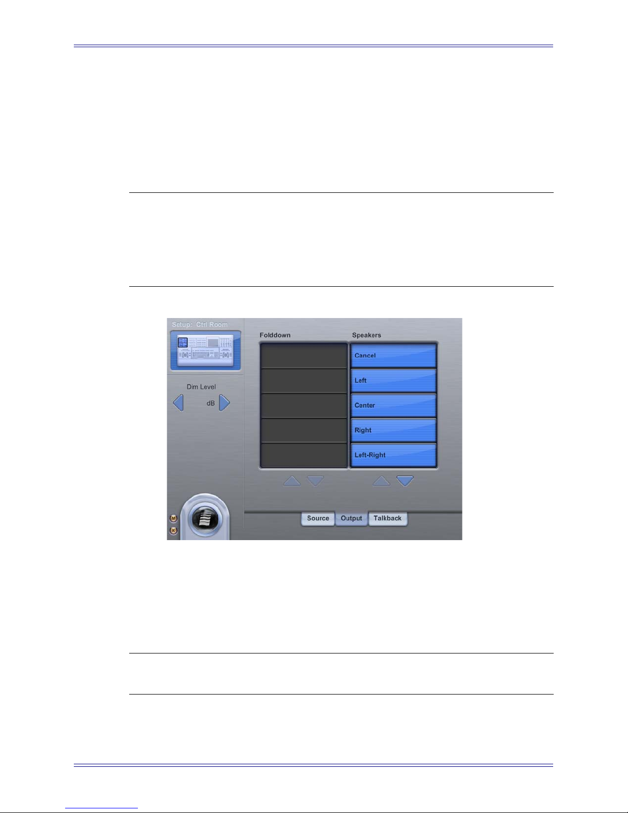
Euphonix Media Application Controller Operation Manual DAW Integration
Press the Control Room Setup button on the MC to open the Control Room Setup
Touchscreen. There are three tabs:
Source: This selects what the Control Room section monitors. The Mix bus, the default
bus in Nuendo’s VST Devices Output tab (denoted by an orange speaker icon next to
its name) is always available. If Studio or External Input busses have been created, they
also appear.
NOTE: Due to Nuendo's internal mixing structure, only one external input can be mon-
itored at a time. Thus, no matter how many of the six External Input busses are
used in the VST Connections->Studio tab, there will be only one Ext. selection
on the MC's Touchscreen. To switch between External Inputs, you must use
Nuendo's Control Room Overview (Devices menu) and click on the available
External Input crosspoint boxes.
Figure 11-5 Output tab in Control Room Setup Touchscreen
Output: This allows soloing one or more speakers. Touch the speakers in the Speaker
list to solo. They change to cyan to show that they are soloed. The Left-Right option is
a shortcut for a stereo feed: it automatically solos the Left and Right speakers. Touch
the Cancel button at the top to turn off all solo assignments.
NOTE: The Folddown and Dim Level controls shown on this tab are not enabled for
use with Nuendo’s Control Room Mixer at this time.
96
Page 97
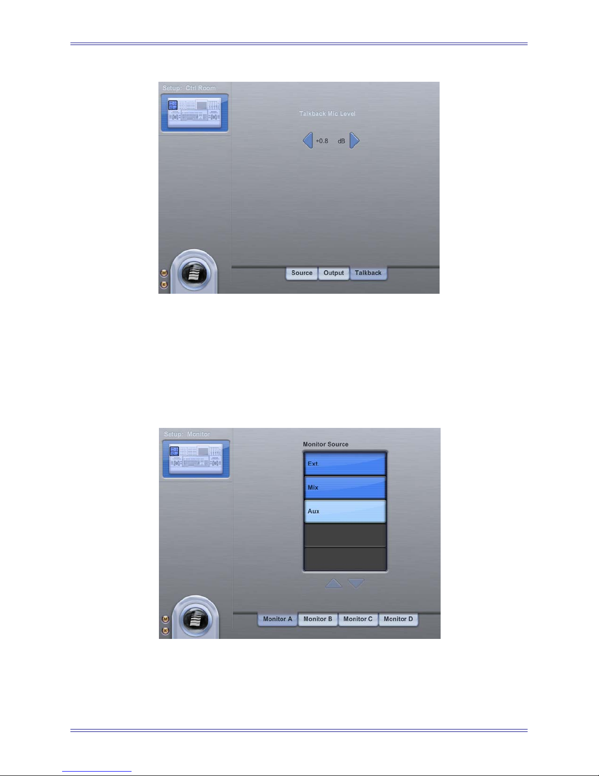
Euphonix Media Application Controller Operation Manual DAW Integration
Figure 11-6 Talkback tab in Control Room Setup Touchscreen
Talkback: If a Talkback bus was created in Nuendo’s VST Devices Studio tab, pressing the MC’s Talkback button enables the talkback function in the Nuendo Control
Room Mixer. The Talkback Mic Level adjustments on the Touchscreen do not function
with Nuendo’s Control Room Mixer at this time.
Monitor Setup
Figure 11-7 Monitor Touchscreen
97
Page 98

Euphonix Media Application Controller Operation Manual DAW Integration
The Monitor Setup key opens the Monitor Touchscreen, which controls the source for
each Studio feed. Each Studio feed has its own tab (Monitor A–D), and each tab lists
the possible sources (External Input, Main, and Aux busses). To select a source for a
Studio bus, touch the tab of the desired bus then touch the source to assign; source selections intercancel.
11.2.4 Talkback
Once the Talkback bus is set up (see page 93), pressing the MC’s Talkback button automatically dims all output bus levels and routes the Talkback bus output to all output
busses with TE enabled in the Nuendo Control Room Mixer (green when enabled). To
utilize the MC’s built-in talkback mic, connect the XLR talkback mic output on the rear
panel to an input on your Nuendo workstation’s hardware (ASIO sound card), then select
that input as the source for the Talkback bus (Device Port in the Studio tab of the VST
Devices window). The MC’s built-in talkback mic is a condenser microphone and requires 48-V phantom power.
NOTE: The rear panel Foot Switch jack can be used to toggle Talkback on/off (see
page 16).
11.2.5 Nuendo-Specific MC Controls
This section discusses MC controls that have a unique function within Nuendo.
Soft Keys
Soft Keys may be programmed with three Nuendo-specific commands by selecting MC
type commands.
• Parameter Collect: Stores automation data into the MC’s internal memory
buffer for punching into Nuendo’s automation system at specified locations.
• Parameter Punch: Transmits automation data collected into the MC’s internal
memory.
• Read/Write All Automation: Used in conjunction with Parameter Collect and
Parameter Punch to isolate automation system from automation being collected
into the MC’s internal memory buffer.
Multiple Track Selection
Multiple track selection from the surface depends on the Track Selection mode preference found on the General Preferences page. Track Selection mode can be set to In-
tercancel or Sum.
• Intercancel: Multiple track selection from the surface is not possible.
• Sum: Multiple track selection is accomplished by pressing Chan Select either
from the MC Touchscreen or on the channel strips. De-select a selected track
by pressing Chan Select again.
98
Page 99
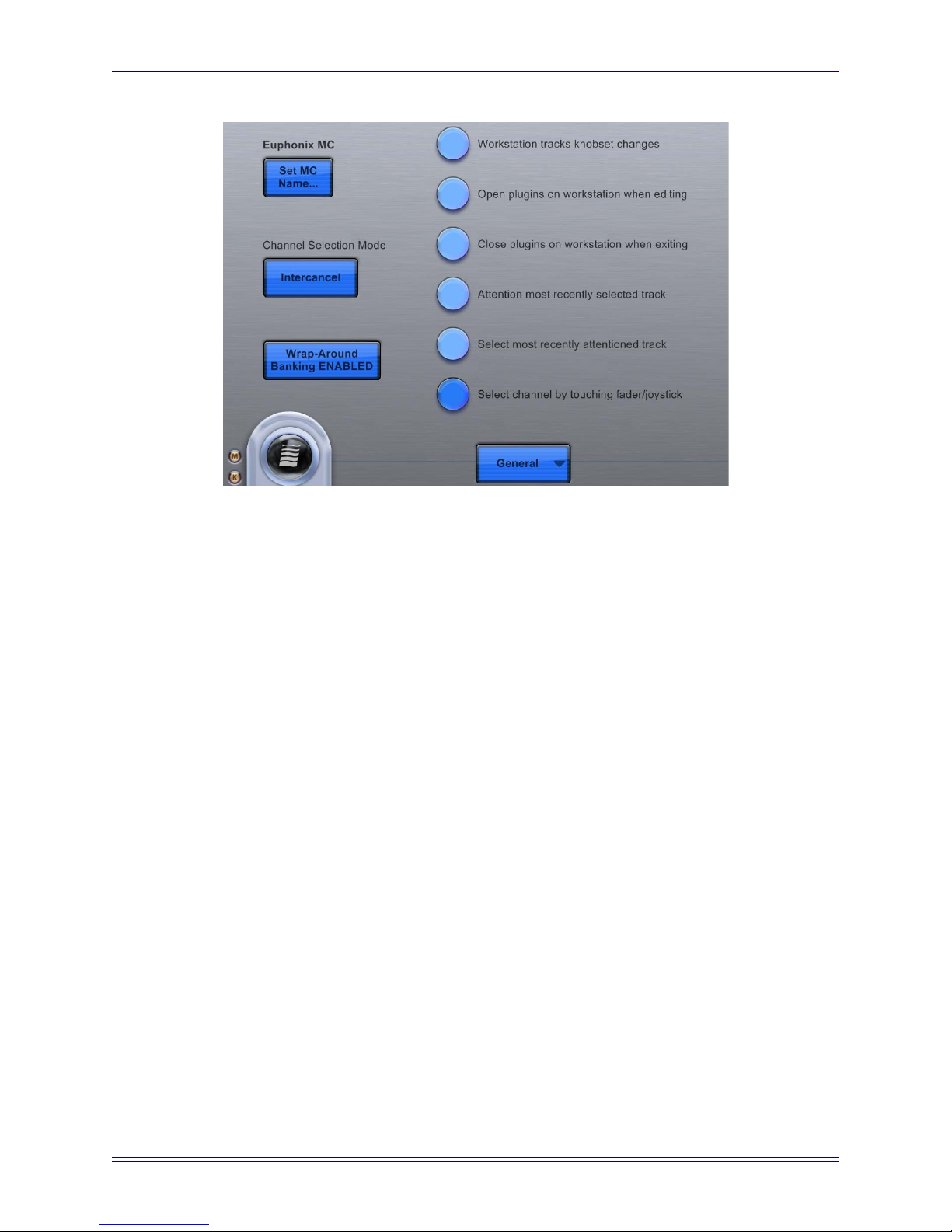
Euphonix Media Application Controller Operation Manual DAW Integration
Figure 11-8 Preferences-General Touchscreen
MIDI Tracks
Nuendo MIDI tracks are supported on the surface. The Insert, Dyn, Pan, Insert, and Mix
Knobsets can be used with Nuendo MIDI tracks.
The Insert Knobset has only four insert slots (audio channels have eight). Insert MIDI
plugins can be modified and automated in the Insert Knobset on MIDI tracks. Bypass
has no effect on MIDI inserts.
The Pan Knobset allows stereo-only panning of MIDI devices. On a joystick MC, the
joystick controls stereo-only panning on the attentioned MIDI track.
The Dyn Knobset selection opens the first Compress MIDI plugin when loaded into one
of the insert slots (MIDI plugin instantiation is only possible with the trackball at this
time). Knobs in the Dyn Knobset allow modification and automation of parameters of
Nuendo Compress plugins.
VSTi Tracks
VSTi tracks have only slightly different features than audio channels. The Record and
Monitor buttons and are disabled, Instantiation of VSTi's is only possible with the
trackball, and the Input Knobset is non-functional. Otherwise, VSTi tracks function
identically to audio channels.
EuCon Adapter Preferences
This section discusses EuCon Adapter Preferences for track assignment and transport
control.
99
Page 100

Euphonix Media Application Controller Operation Manual DAW Integration
Dynamic Selection of EuCon-ized Tracks
A list of checkboxes determines which channel types are modeled in EuCon. If a certain
channel is available in Nuendo and the corresponding checkbox is checked, the channel
can be accessed through EuCon and is deemed EuCon-ized.
Figure 11-9 Nuendo EuCon Preferences
100
 Loading...