

Page 1
Operation Manual
Document Revision: 3.0
Software Version: 3.0
Part Number: 840-08718-06
Release Date: September 2007
Euphonix, Inc.
220 Portage Ave.
Palo Alto, California 94306
Phone: 650-855-0400
Fax: 650-855-0410
Web: http://www.euphonix.com
e-mail: info@euphonix.com
Page 2

In the interest of continued product development, Euphonix reserves the right to make improvements to this manual and the product it describes at any time, without notice or obligation.
System 5, S5, PatchNet, eMix, EuCon, R1, Studio Hub, Audio Deck, Max Air, Reel Feel, Clear
Displays, Track Panner, SnapShot Recall, DSC (Digital Studio Controller), Hyper-Surround,
Total Automation and Mix View are trademarks of Euphonix, Inc.
Manual design by Rob Wenig.
Manual written by Tim Driedger, Steve Milne, Duane Takahashi, Martin Lucas and Rob Wenig.
©2007 Euphonix, Inc. All rights reserved worldwide. No part of this publication may be reproduced, transmitted, transcribed, stored in a retrieval system, or translated into any language in
any form by any means without written permission from Euphonix, Inc.
Note: This equipment has been tested and found to comply with the limits for a Class A
digital device pursuant to Part 15 of the FCC Rules. These limits are designed to
provide reasonable protection against harmful interference when the equipment is
operated in a commercial environment. This equipment generates, uses, and can
radiate radio frequency energy and, if not installed and used in accordance with
the instruction manual, may cause harmful interference to radio communications.
Operation of this equipment in a residential area is likely to cause harmful interference in which case the user will be required to correct the interference at his own
expense.
Caution:Any changes or modications made by the user that are not expressly approved
by Euphonix could void the user’s right to operate the equipment.
Page 3
IMPORTANT SAFETY INSTRUCTIONS
The lighting ash with arrowhead symbol within an equilateral triangle, is
intended to alert the user to the presence of uninsulated “dangerous voltage”
within the product’s enclosure that may be of sufcient magnitude to constitute a
risk of electrical shock to persons.
The exclamation point within an equilateral triangle, is intended to alert the user
to the presence of important operating and maintenance (servicing) instructions
in the literature accompanying the product.
Read these instructions.1)
Keep these instructions.2)
Heed all warnings.3)
Follow all instructions.4)
Do not use this apparatus near water.5)
Clean only with a dry cloth.6)
Do not block any ventilation openings. Install in accordance with the manufacturer’s in-7)
structions.
Do not install near any heat sources such as radiators, heat registers, stoves, or other appara-8)
tus (including ampliers) that produce heat.
Do not defeat the safety purpose of the polarized or grounding-type plug. A polarized plug 9)
has two blades with one wider than the other. A grounding type plug has two blades and a
third grounding prong. The wider blade or the third prong are provided for your safety. If
the provided plug does not t into your outlet, consult an electrician for replacement of the
obsolete outlet.
Protect the power cord from being walked on or pinched particularly at plugs, convenience 10)
receptacles, and the point where they exit from the apparatus.
Only use attachments/accessories specied by the manufacturer.11)
Use only with the cart, stand, tripod, bracket, or table specied by the manufacturer, or sold 12)
with the apparatus. When a cart is used, use caution when moving the cart/apparatus combination to avoid injury from tip-over.
Page 4

Unplug this apparatus during lightning storms or when unused for long periods of time.13)
Refer all servicing to qualied service personnel. Servicing is required when the apparatus 14)
has been damaged in any way, such as power-supply cord or plug is damaged, liquid has
been spilled or objects have fallen into the apparatus, the apparatus has been exposed to rain
or moisture, does not operate normally, or has been dropped.
WARNING – TO REDUCE THE RISK OF FIRE OR ELECTRIC SHOCK, DO NOT EX-15)
POSE THIS APPARATUS TO RAIN OR MOISTURE.
Do not expose this equipment to dripping or splashing and ensure that no objects lled with 16)
liquids, such as vases, are placed on the equipment.
To completely disconnect this equipment from the AC Mains, disconnect the power supply 17)
cord plug from the AC receptacle.
The mains plug of the power supply cord shall remain readily operable.18)
This unit is provided with a power supply cord set suitable for 120V AC input only (for 19)
U.S.A. and Canada). For other than U.S.A. and Canada, a qualied person must provide for
use with this unit, an appropriate, approved power supply cord set which is in compliance
with the end use country requirements and has a minimum cross-sectional area of 1.0mm2.
For units with more than one power cord:20)
Caution: This unit has more than one power supply cord. Disconnect two power supply
cords before servicing to avoid electrical shock.
Attention: Cet appareil comporte plus d’un cordon d’alimentation. An de prévenir les
chocs électriques, débrancher les deux cordons d’alimentation avant de faire
le dépannage.
Operator Accessible Fuse:21)
Caution: For continued protection against risk of re, replace only with same type and
rating of fuse.
Attention: Pour ne pas compromettre la protection contre les risques d’incendie, rem-
placer par un fusible de même type et de même caractéristiques nominales.
Page 5

Euphonix Max Air Mixing Console Operation Manual
Table of Contents
List of Figures viii
Chapter 1: Introduction 17
1.1 How to Use This Manual 17
1.2 Overview of the System Components 19
1.2.1 DF66 SuperCore 19
1.2.2 Analog and Digital I/O 19
1.2.3 Control Surface 21
1.3 Additional Hardware Components 22
1.4 Max Air Startup Sequence 23
Chapter 2: New Features in Version 3.0 25
Chapter 3: Quickstart to Common Tasks 27
3.1 Create a Title 27
3.2 Initial Router and Patchbay Setup 28
3.2.1 Name Ports 28
3.2.2 Assigning the Mic Preamps to Hubs 29
3.2.3 Label Individual Signals 30
3.2.4 Label Destination Ports and Signals 30
3.3 Channel to Strip Layout 31
3.3.1 Setting up Stereo Channels using MF Masters 31
3.3.2 Assign Channels to Strips 32
3.4 Busses 33
3.4.1 Create Main Sections and Audio Subgroups 33
3.4.2 Route to the Main Sections and Busses 36
3.4.3 Using the 24 Group Busses 36
3.5 Meters 37
3.5.1 Setting the Fader Meters On Each Strip 37
3.5.2 Screen Meters on the Touchscreen 37
3.5.3 External Meters Display 38
3.6 Knobsets 39
v
Page 6

Euphonix Max Air Mixing Console Operation Manual
3.6.1 Creating a Custom Knobset for Mono Channels 39
3.6.2 Creating a Custom Knobset for Stereo Channels 40
3.7 External Device Setup 40
3.7.1 Patching External Devices into the External Inputs 40
3.7.2 Assign External Inputs a Format and a Button 41
3.8 Monitors 42
3.9 Save a Default Title 43
Chapter 4: Touchscreen 45
4.1 Introduction to the Touchscreen 45
4.2 File 49
4.2.1 Projects 49
4.2.2 Titles 51
4.2.3 Operations on the Current Title 52
4.2.4 Default Titles 53
4.3 Patch 54
4.3.1 Destinations and Sources 55
4.3.2 Console I/O 55
4.3.3 Cabling 60
4.4 Patching Examples 63
4.4.1 Patch 12 Mics Into Channels 25–36 63
4.4.2 Main Bus Send/Return 67
4.4.3 Monitor Patching 68
4.4.4 Solo Bus and Utility Patching 68
4.4.5 Talkback Signal Patching 68
4.5 Busses 69
4.6 System 69
4.6.1 Externals 69
4.6.2 *Knobset 70
4.6.3 Mixer Model 71
4.6.4 Preferences 72
4.6.5 About 73
4.7 Channels 74
4.7.1 Multi Format Masters 74
vi
Page 7

Euphonix Max Air Mixing Console Operation Manual
4.7.2 Control Groups 74
4.8 Surface 74
4.8.1 Assign 74
4.8.2 Layouts and Snapshots 76
4.8.3 Spill Area 76
4.8.4 Lock Strips 77
4.8.5 Fader Unity 77
4.9 Status 78
4.10 Super Channel 80
4.10.1 Process Order 81
4.10.2 Main and Group Bus Routing 82
4.11 Meters 83
4.11.1 Presets 83
4.11.2 Screen 84
4.11.3 Fader 87
4.11.4 Setup 88
4.12 Events 88
Chapter 5: Channels and Strips 89
5.1 Strips 89
5.1.1 Assign Channels to Strips 91
5.2 Channel Control Features 93
5.2.1 Channel Name 93
5.2.2 Fader 94
5.2.3 Meters 95
5.2.4 Status LEDs 95
5.2.5 Wave Key 95
5.2.6 Channel On Key 95
5.2.7 Channel Select Key 96
5.2.8 Solo Key 96
5.2.9 Copy and Paste 96
5.2.10 Rotary Knobs 96
5.2.11 Knobset Select Keys 97
5.2.12 In/Out Keys 98
5.2.13 Expand 98
vii
Page 8

Euphonix Max Air Mixing Console Operation Manual
5.3 Channel Processing Functions 98
5.3.1 Inputs 98
5.3.2 Dynamics 101
5.3.3 EQ 102
5.3.4 Filters 103
5.3.5 Pan 104
5.3.6 Aux Busses 106
5.4 Channel Processor Order and Patch Points 107
5.4.1 Channel Processor Order 107
5.4.2 Insert Point 107
5.5 Channel Routing Functions 108
5.5.1 Group Bus Routing 108
5.5.2 Main Bus Routing 109
5.6 Mix Minus 110
Chapter 6: Busses 111
6.1 Introduction to Max Air Busses 111
6.2 Conguring Main and Group Busses 112
6.2.1 Format Selector 113
6.3 Conguring Aux Busses 116
6.3.1 Aux to Faders 116
6.3.2 Toggle On/Off 117
6.3.3 Toggle Pre/Post 117
6.3.4 Copy Fader to Aux 117
6.3.5 Copy Aux to Aux 118
6.3.6 Set Unity 118
6.3.7 Level To Off 118
6.3.8 Toggle Stereo 118
6.4 Mix Minus 119
6.5 Bus Centric Views 120
6.5.1 Group Bus View 120
6.5.2 Aux View 120
6.5.3 Main View 122
6.6 Bus Masters 123
viii
Page 9

Euphonix Max Air Mixing Console Operation Manual
6.6.1 Main Section Masters 123
6.6.2 Group and Aux Bus Masters 124
6.6.3 Bus Inserts 124
6.7 Bus Processing 125
Chapter 7: Center Section 126
7.1 Super Channel 127
7.1.1 Assign a Channel to the Super Channel 128
7.1.2 Input Section 129
7.1.3 Pan 129
7.1.4 Filters 130
7.1.5 Insert 130
7.1.6 EQ 130
7.1.7 Dynamics 131
7.1.8 Fader 131
7.2 Monitors and Control Room 132
7.2.1 Monitors 133
7.2.2 Control Room 134
7.3 Talkback/Slate 137
7.3.1 Talkback 138
7.3.2 Listenback 139
7.3.3 Slate 140
7.4 Oscillator 140
7.5 Solo 142
7.5.1 Solo Mode 143
7.5.2 Solo Level 143
7.5.3 Clear Solo 143
7.5.4 Solo Switch Mode 143
7.5.5 Speaker Selection 144
7.5.6 Solo Speaker Dim 144
7.5.7 Solo-Safe 144
7.5.8 Backstop PFL 145
7.6 Soft Knobs 145
7.6.1 Soft Knob Setup Popup 146
7.7 Center Section Faders 147
ix
Page 10

Euphonix Max Air Mixing Console Operation Manual
7.8 Keypad 148
7.9 Global Functions 150
7.10 Custom Keys 151
Chapter 8: Control Groups and Multi Format Masters 152
8.1 Control Groups 152
8.1.1 Create a Control Group 152
8.1.2 Assign Control Group Master to Strip 153
8.2 Multi Format Master Channels 154
8.2.1 Create a Multi Format Master Channel 154
8.3 Control Groups or Multi Format Masters 155
8.4 Spill 156
Chapter 9: Layouts and Snapshots 157
9.1 Layouts 157
9.1.1 Store 158
9.1.2 Recall 158
9.1.3 Name 158
9.1.4 Clear 158
9.2 Snapshots 159
9.2.1 Store 159
9.2.2 Recall 161
9.2.3 Name 161
9.2.4 Clear 161
Chapter 10: Scene Automation 162
10.1 Scene List 162
10.1.1 Scenes 162
10.1.2 Scene Menu 163
10.1.3 Add Scene 163
10.1.4 Insert Scene 163
10.1.5 Delete Scene 163
10.1.6 Take 163
10.1.7 Finish 164
10.1.8 Previous and Next 164
x
Page 11

Euphonix Max Air Mixing Console Operation Manual
Chapter 11: Event System 165
11.1 Input Types 166
11.2 Output Types 167
11.3 Logical Operators 168
11.4 Event Conguration Display 169
11.5 Event List 169
11.6 Input 170
11.7 Output 171
11.8 Deleting Events 171
11.9 Event Trigger on Title Load 171
11.10 GPI Examples 172
11.10.1 Creating an “On-Air” Tally 172
11.10.2 Using a Channel Strip to Control a Cart Machine 175
11.10.3 Audio Follow Video 177
xi
Page 12

Euphonix Max Air Mixing Console Operation Manual
xii
Page 13

Euphonix Max Air Mixing Console Operation Manual
List of Figures
1-1 Typical Max Air Hardware Conguration 20
1-2 Max Air Control Surface 21
3-1 Console Sources 28
3-3 Monitor Routing 42
4-1 Keyboard Popup 45
4-2 Touchscreen Main Menu Buttons 46
4-3 Touchscreen Main View 47
4-4 Touchscreen Navigation 48
4-5 Drives View 49
4-6 Projects View 50
4-7 Titles View 51
4-8 Save Current Data Popup 52
4-9 Current Title Buttons 52
4-10 Simplied MADI routing diagram 54
4-11 Sources and Destinations with respect to Max Air 55
4-12 Console I/O -A and B Inputs View 56
4-13 Sources and Destinations Selected 57
4-14 Patch Complete 58
4-15 Source input naming 59
4-16 Sources patched to channels 59
4-17 Cabling: MADI Out Port 61
4-18 Cabling: MADI In Port 62
4-19 Sources View with 12 Mic-Line Sources Selected 63
4-20 Selecting Destination Channels 65
4-21 Mic Patch Complete 65
4-22 Sources Selected 66
4-23 R-1 and Mics Patched 67
4-24 Main Bus Send and Return 67
4-25 Externals View 69
4-26 Knobset View 70
xiii
Page 14

Euphonix Max Air Mixing Console Operation Manual
4-27 Mixer Model View 71
4-28 Preferences View 72
4-29 Channels Tabs 74
4-31 Assign View 75
4-32 Spill Area function 76
4-33 Lock Strips View 77
4-34 Fader Unity popup 78
4-35 Status View 79
4-36 Super Channel View 80
4-37 Channel Selector Popup 81
4-38 Process Order Popup 81
4-39 Channel Routing Popup 82
4-40 Meters-Presets Popup 83
4-41 Meters-Screen Popup with Meters Display 84
4-42 Meters-Screen=Ext1 Popup with Meters Display 85
4-43 External Meters Display, fully congured 86
4-44 Meters-Fader Popup 87
4-45 Meters-Setup View 88
5-1 Console Strip and Bus display with block diagrams for Main and Swap channels 90
5-2 Channel Assign View 91
5-3 Channel Selector 93
5-4 Main and Swap Channel displays 93
5-5 Strip Fader 94
5-6 Rotary Knob Controls 97
5-7 Strip Function Switches 97
5-8 Mono Input knobsets 98
5-9 Stereo Input Knobsets 100
5-10 Dynamics knobsets 101
5-11 EQ knobsets 102
5-12 Filters knobsets 103
5-13 Pan Knobsets 104
5-14 Aux bus Knobset 106
xiv
Page 15

Euphonix Max Air Mixing Console Operation Manual
5-15 Channel processor order and patch points 107
5-16 Group Bus Routing Knobsets 108
5-17 Main Section Routing Knobset 109
5-18 Mix Minus Processing 110
6-1 Main Bus View 112
6-2 Group Bus View 113
6-3 Format Selector 114
6-4 Aux Bus Settings View 116
6-5 Mix Minus Conguration-Strips View 119
6-6 Group Bus View-Strips 120
6-7 Aux Bus View-Channels 121
6-8 Main View: A-Channels 122
6-9 CM404 Center Section with Soft Knobs 123
6-10 Bus Processing Conguration 125
7-1 CM404 Master Module 126
7-2 CM404 Super Channel Controls 127
7-3 Super Channel: Selected Channel, Pan, Filters, and Input 128
7-4 Super Channel: EQ, Insert 130
7-5 Super Channel: Dynamics 131
7-6 Monitoring Matrix 132
7-7 CM404 Monitor Controls 133
7-8 Monitors Setup Popup 133
7-9 Control Room Setup: CR Source 135
7-10 Control Room Setup: CR Output 135
7-11 CM404 Talkback/Slate 137
7-12 Talkback/Slate Setup Popup 138
7-13 Listenback Setup Popup 139
7-14 Slate Setup Popup 140
7-15 CM404 Oscillator 141
7-16 Oscillator Setup Popup 141
7-17 CM404 Solo Controls 142
7-18 Solo Setup Popup 142
xv
Page 16

Euphonix Max Air Mixing Console Operation Manual
7-19 Solo Safe Popup 144
7-20 CM404 Soft Knobs 145
7-21 Soft Knobs Setup Popup 146
7-22 CM404 Center Section Faders 147
7-23 CM404 Keypad 148
7-24 Keypad Directory Popup 149
7-25 Global Function Keys 150
7-26 Custom Keys 151
8-1 Control Groups View 152
8-2 Assign Channels to CG View 153
8-3 MF Masters View 154
9-1 Layouts View 157
9-2 Store Layout Popup 158
9-3 Snapshots View 159
9-4 Store Snapshot: Strip View 160
9-5 Store Snapshot: Channel View 161
10-1 Scene Automation Operations View 162
11-1 Event View 169
11-2 Add Input Event Popup 170
11-3 Add Output Event Popup 171
11-4 On-Air Tally On 174
11-5 On-Air Tally Off 174
11-6 Cart Start 176
11-7 Cart Stop 176
11-8 Audio Follow Video Conguration 177
xvi
Page 17

Euphonix Max Air Mixing Console Operation Manual
IntroductionChapter 1:
Congratulations on your purchase of Max Air, a compact high-performance digital mixing console intended for on-air broadcast and live applications. Max Air has been designed to satisfy broadcast audio professionals who demand the highest quality standards. Max Air is the perfect choice for serious broadcast audio production facilities that
require a powerful digital mixing system with an easy-to-use interface.
How to Use This Manual1.1
Euphonix has dedicated substantial time and resources to the Max Air documentation.
We recognize the diverse range of experience among our customers and have written
and organized the manual to be accessible to everyone. Of course it is more fun to use
Max Air than read about it but we assure you that your time reading this manual will be
well spent.
Manual Structure
We recommend that everyone read this introduction in its entirety. The manual contains
the following chapters:
Chapter 3: • Quickstart to Common Tasks: Provides the fastest way to begin using
Max Air’s basic features. Since this chapter depends on using the Touchscreen,
read page 45–48 to acquire introductory knowledge before beginning.
Chapter 4: • Touchscreen: Since Max Air uses Touchscreen software to implement
its ground-breaking user-interface, it is important to get acquainted with this new
technology. We recommend reading this chapter in its entirety.
Chapter 5: • Channels and Strips: Discusses the physical area of the console used to
control channels and the channel processing functions.
Chapter 6:• Busses: Discusses Max Air’s bus system consisting of 24 Main busses,
24 Group busses, 16 Aux busses, and a stereo solo bus.
Chapter 7: • Center Section: Discusses Max Air’s center section including the Su-
per Channel, monitors, talkback/slate, oscillator, solo, Soft Knobs, faders, keypad,
global functions, and Custom keys.
Chapter 8: • Control Groups and Multi Format Masters: Discusses how to use Con-
trol Groups and Multi Format Masters and the difference between them.
Chapter 9: • Layouts and Snapshots: Discusses how to store/recall channel-tostrip
mappings (layouts) to the console and how to store/recall channel functions (snapshots).
Chapter 10: Scene Automation: Describes the scene automation system and how •
to program scenes.
17
Page 18

Euphonix Max Air Mixing Console Operation Manual Introduction
Chapter 11:• Event System: Discusses how to use the event system to program Max
Air.
How to Use the PDF
The Acrobat PDF version of this manual provided in your system can be a valuable “online help” learning tool while using Max Air. We have included some amenities that we
wish to explain for those not familiar with Acrobat:
The Bookmarks on the left serve as a continuously visible table of contents while •
reading. Click on a subject heading to jump to that page. Click a + symbol to
expand that heading to show subheadings. Click the - symbol to collapse the subheadings.
The manual’s table of contents and list of gures are “active links” to their pages. •
Select the “hand” cursor, allow it to hover over the heading and turn into a “n-
ger.” Then click to locate to that subject and page.
All cross references are active links. Allow the “hand” cursor to hover over the •
reference, turn into a “nger,” and click to follow the reference.
Use the left and right arrow keys on the top bar to go back and forth between •
views. This is a great way to follow a cross reference and return to the page from
which you were reading.
Select the • Find item from the Edit menu (Ctrl-F) to search for a subject. This can
be used as an “index on the y.”
Use the magnifying glass tool or the zoom edit box on the top bar to zoom in/out. •
This is helpful when examining a complex graphic or setting the text size for easy
reading online.
Acrobat Reader version 4 or later is required to open the PDF. This can be downloaded
for free at http://www.adobe.com/products/acrobat/readstep2.html.
18
Page 19

Euphonix Max Air Mixing Console Operation Manual Introduction
Overview of the System Components1.2
DF66 SuperCore1.2.1
The DF66 SuperCore performs all Max Air audio processing: dynamics and EQ; Mix,
Group, Aux, and Monitor busses. The DF66 can employ from two to six SP662 DSP
cards, supporting Mixer Models from 68 to 194 channels
Analog and Digital I/O1.2.2
The engineer has complete freedom to decide how to route sources and destinations to
the console from the Touchscreen Patch View, which easily handles 224 digital and analog sources. Max Air can be expanded to accommodate 1536 sources, suitable for large
commercial installations.
Digital and analog I/O units connect all of the devices in the studio via MADI. All audio
signals are converted to and from the MADI format through analog and digital converters. The basic Max Air system includes eight MADI Inputs and seven Outputs to connect I/O devices. Additional MADI ports can be added by expanding the system with up
to six SP662 DSP cards. Each 75- Ω coaxial MADI cable can carry up to 56 channels
of 24-bit digital audio at 44.1 or 48 kHz. These MADI inputs and outputs appear at the
console’s internal router/patchbay. See Console I/O on page 55 for more information.
Microphone Inputs
Microphone inputs are handled by the ML530 Mic/Line Interfaces or the Modular I/O
System.
Each ML530 unit contains 24 remote-controlled microphone preamps, connected
to a dedicated AM713 Analog to MADI Conveter. A system can include up to seven
ML530s.
Each Modular I/O System frame can contain from 4 to 64 remote-controlled microphone
preamps. A system can include up to four frames.
19
Page 20
Euphonix Max Air Mixing Console Operation Manual Introduction
MC524
Monitor Interface
MA703
MADI to Analog
MIDI I/F
GPI/O
MA703
MADI to Analog
AM713
Analog to MADI
ML530
Analog Mic/Line
AM713
Analog to MADI
Talk & Listen
Mics
Speakers
FC726
Digital
FC726
Digital
Ethernet
Control
MADI
Analog Audio
Digital Audio
24
24
24
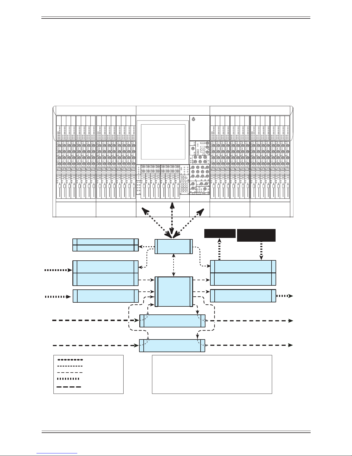
Typical Max Air Configuration
107 Full Channel Signal Paths
Inputs: 112 Digital, 24 Mic, 24 Line = 160
Ouputs: 112 Digital, 24 Line = 136
56 Digital
56 Digital
56 Digital
56 Digital
System
Computer
CM404
Center Section
CM416
Sixteen Fader Module
CM416
Sixteen Fader Module
DF66
SuperCore
Monitoring
The MC524 Monitor Controller provides analog monitor outputs. This unit provides
Main (7.1), Alt 1 (5.1), and Alt 2 (stereo) control room monitoring, SLS (7.1), and Cues
1–3 (each stereo) studio monitoring, two talkback preamps, and four listen microphone
preamps. The MC524 is connected to a dedicated MA703 MADI to Analog Converter.
Typical Max Air Hardware Conguration (Modular I/O not shown)Figure 1-1
20
Page 21
Euphonix Max Air Mixing Console Operation Manual Introduction
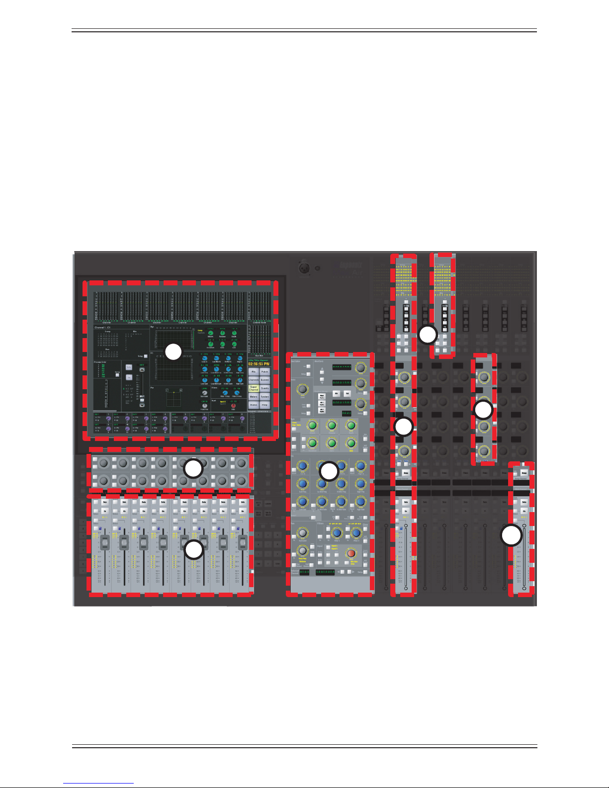
4
5
6
8
1
2
3
6
7
Control Surface1.2.3
Max Air features a professional modular control surface that can be easily congured
to suit a variety of operational layouts. The CM416 module contains sixteen identical
strips, the physical area on the console that contains keys, knobs, displays, and a fader.
Channels perform all of the signal processing (EQ, dynamics, routing, gain, etc.). The
control surface connects to the DF64 via ethernet and the EuCon Hub; audio does not
pass through the control surface.
The Max Air control surface consists of a CM404 center section with Touchscreen (1),
Super Channel (4), Soft Knobs (2) and 8 center section faders (3). The channel strips (5),
of which there can be a total of 48 (3 CM416 modules), contain a function select area (6),
four assignable knobs (7) and a fader (8).
Max Air Control SurfaceFigure 1-2
21
Page 22

Euphonix Max Air Mixing Console Operation Manual Introduction
Channels and Strips
A CM416 module contains sixteen identical Strips. The Strip is the physical control area
on the console that contains keys, knobs, displays, and a fader. A Channel performs all
of the signal processing (EQ, dynamics, routing, gain, etc.). Max Air has 96 channels,
each of which may be assigned to a Strip. A Strip has room for Swap and Main channels
that can be switched with one button press. Max Air allows tremendous exibility with
how Strips are assigned channels and how they are controlled.
Channel Format
Most analog consoles are limited to mono or stereo channels. Max Air supports mono
and stereo channels as well as LCRS, 5.1, 6.1, and 7.1 Multi Format Masters (Chapter 8:
Control Groups and Multi Format Masters).
Additional Hardware Components1.3
The following hardware devices are also used in the Max Air system:
System Computer (SC261)• : Runs the Max Air Touchscreen software applica-
tion; all le management and system setup is done from this computer.
See Chapter 4: Touchscreen.
Failover Switch: • This optional device can be used to connect to a backup DSP
SuperCore in parallel with the primary unit for complete redundancy of MADI
I/O, Router, and DSP Processing.
NOTE: This brief description to the Max Air hardware components is intended to in-
troduce the reader to the audio path in and out of the system. More detailed
information about all of the hardware is covered in the Max Air Technical
Manual.
22
Page 23

Euphonix Max Air Mixing Console Operation Manual Introduction
Max Air Startup Sequence1.4
With all system components turned off:
Turn on all of the surface modules.1.
Turn on the SC263 System Computer2.
Make sure the system digital sync source and Eucon switch is on.3.
Turn on the Failover Switch (if present), all I/O units, the MOTU MIDI Interface 4.
and the GP132.
The System Computer will nish booting to the Windows desktop.5.
With the system computer booted and the Failover Switch (if present), all I/O units, the
MOTU MIDI Interface and the GP132 turned on:
Double-click the 1. Max Air icon on the desktop.
Turn on the DF66.2.
If the modules on the system have previously been saved as default, Max Air will 3.
continue to boot when all modules reach 100%.
If modules appear as 4. Unexpected, the user can select all of the modules by holding
down the Ctrl key on the keyboard and selecting each of them. When all modules
are selected, touch Save selected as default, and conrm the selection by clicking
OK.
Click 5. Continue to nish booting.
Since Max Air has been designed for live, on-air applications, the system is designed
to tolerate variations in the startup sequence. The system will boot properly if power is
applied to all components simultaneously. If this occurs, be sure to check that all components are properly locked to a valid master digital sync source.
To restart the system:
Shutdown the System PC with the 1. Shutdown button in the About View.
Reset the CM404 and CM416 surface modules.2.
Power off the DF66 core.3.
Power on the System PC.4.
Since this takes the longest to boot, power it up rst.
Power on the DF66.5.
The DF66 must be off for 5 s before powering back on to discharge the PSUs.
The system will boot the rest of the way by itself.6.
23
Page 24

Euphonix Max Air Mixing Console Operation Manual Introduction
24
Page 25

Euphonix Max Air Mixing Console Operation Manual
New Features in Version 3.0Chapter 2:
Scene Automation
Scene Automation allows the manual triggering of a single snapshot, or a sequence of
snapshots. Cross-fading to a scene can be programmed by setting fader/knob glide times.
A delay time between scenes can also be programmed.
DF66 SuperCore
Support for the DF66 SuperCore DSP platform.
Failover Option
Support for the DF66 Failover Option. Ensures 100% redundancy of MADI I/O, routing,
and DSP functionality.
Meter Bridge Display
The Meter Bridge Display option allows the user to view up to 28 additional sets of meters on an external display.
UI Enhancements
New User Interface enhancements to accommodate larger Mixer Models, Bus Processing and general user interaction.
Enhanced Logging Capabilities
Enhanced logging capabilities capture a larger data set, including snapshot and layout
recall events. The System Computer log history will be available over muliple system
reboots with a new Rotating Log feature.
Changeover Event
New Event system “Changeover” Event input type.
Longer Delay Function
A longer delay function of up to 2 seconds with 3 separate display options (frames,
samples, and seconds).
Bus Processing
User-assignable Bus Processing functionality is added to Bus Sections, Group Busses,
and Aux Busses. These functions include a limiter, compressor, and lters.
Auto-Update of DSP Software
The DF66 will automatically check the System PC’s software version and update its own
software version if necessary to insure compatibility.
25
Page 26

Euphonix Max Air Mixing Console Operation Manual New Features in Version 3.0
Modular IO
Modular I/O congurations consist of one or more 3RU double-sided frames that can be
tted with a variety of I/O modules. For interface to the console, all signals are converted
to MADI. Depending on the conguration, a maximum signal density of 56 inputs and
56 outputs can be achieved on a single MADI I/O. Audio formats supported are remotecontrolled preamp, line level analog, AES/EBU, and HD/SD embedder/de-embedder.
These formats can be used simultaneously in the same frame. Refer to the Euphonix
Modular Conguration Guide for more details and conguration possibilities.
26
Page 27

Euphonix Max Air Mixing Console Operations Manual Quickstart to Common Tasks
Quickstart to Common TasksChapter 3:
Since this chapter depends on using the Touchscreen, please read page 45–48 to acquire
introductory knowledge before beginning.
Create a Title3.1
We will begin by creating a Title that allows you to save console and patch settings for
later recall.
On the Touchscreen:
Select 1. File from the Main Menu buttons.
Select the 2. Drives tab.
Select the 3. C: drive (the C: Local Disk drive).
Select the 4. Projects tab.
Create a new Project by touching the 5. New button.
A Project is a folder that contains titles for a show, location, or operator.
Name the project using the keyboard popup and press 6. Enter.
Select 7. Titles tab.
Create a new Title by pressing the 8. New button.
A Title can contain all settings for a show, each engineer can have their own Title,
different Titles can be used for different versions of the same show.
Name the Title using the keyboard popup and press 9. Enter.
To save the current console setup into the newly created Title, press 10. Yes when
prompted to Save Current Data. To clear the console setup back to the Default
Title settings, press No to save the new title without the current console settings.
27
Page 28
Euphonix Max Air Mixing Console Operations Manual Quickstart to Common Tasks
AM713
Analog to MADI
ML530
Analog Mic/Line
AM713
Analog to MADI
24 Mic
24 Line
FC726
Digital
FC726
Digital
56 Digital
56 Digital
USED
Analog 1-24
Digital In 1
Digital In 2
Mic 1-24
Unused
Unused
Unused
Unused
Unused
Unused
Initial Router and Patchbay Setup3.2
Max Air has an internal router that acts as a digital patchbay, allowing connection to
Sources, Console I/O and Destinations.
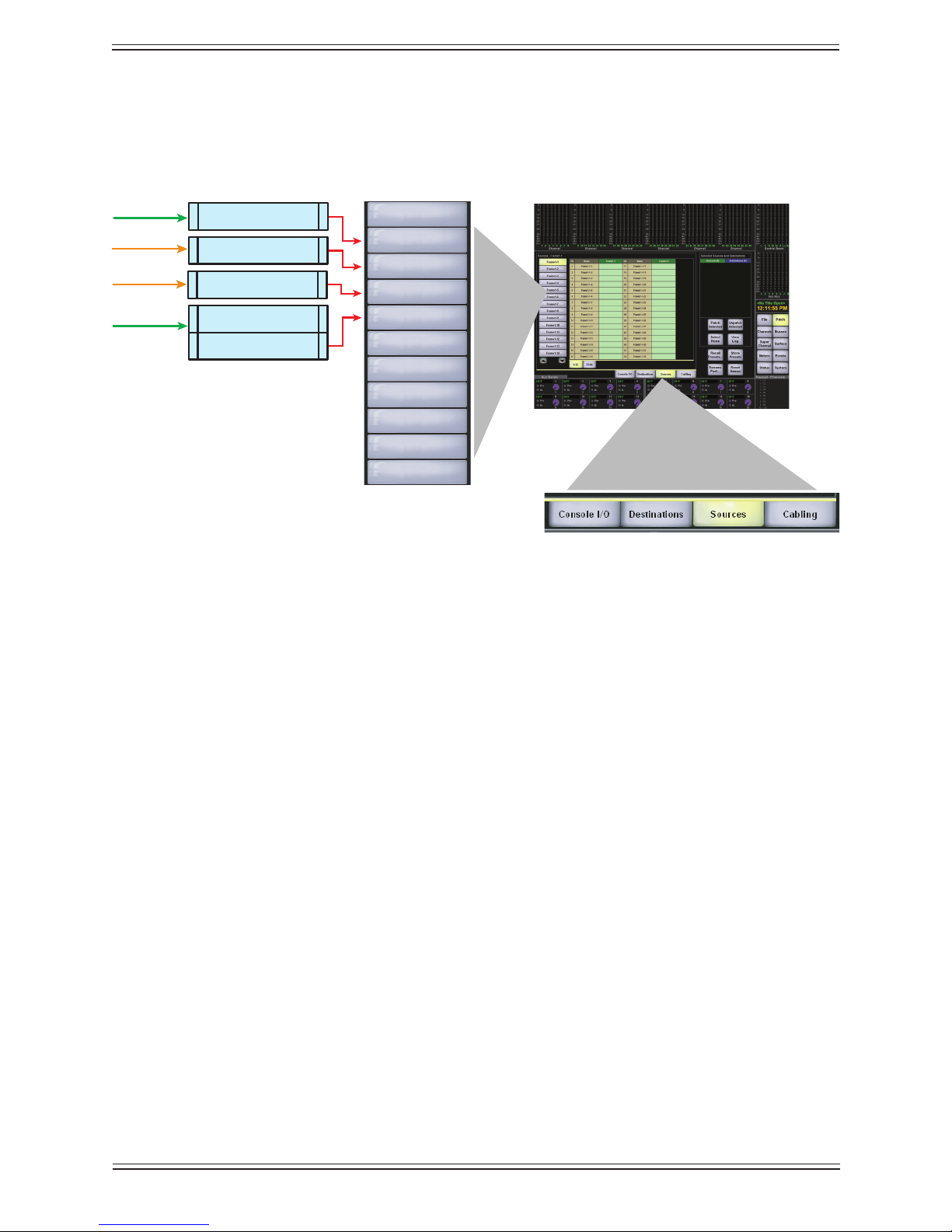
Console SourcesFigure 3-1
Each button along the left of the Patch view (Figure 3-1) represents a MADI connection to an I/O device. These MADI “Ports” are initially labeled as Frame x-x. We will
start by renaming these inputs and outputs and the individual sources and destinations
to meaningful labels. This is like labelling a patchbay with the equipment available for
patching. Once this is done these settings can be saved as the Default Title and used for
newly created Titles. Commonly used patches can be added to the Default Title setup in
the same way a traditional patchbay can be normalled.
Name Ports3.2.1
Select 1. Patch from the Main Menu buttons on the right of the Touchscreen.
Select the 2. Sources tab in the Patch view.
We will rename ports to match the connections of the system shown in Figure 1-1. The
rst MADI input (Frame1-1) is connected to 24 Mic Preamps.
Select 3. Frame1-1 on the left of the screen.
Touch 4. Rename Port. Type USED (Mics 1-24) using the keyboard popup.
28
Page 29

Euphonix Max Air Mixing Console Operations Manual Quickstart to Common Tasks
Select 5. Frame1-2 and touch Rename Port. Type Analog 1-24.
Select 6. Frame1-3 and touch Rename Port. Type Digital In 1.
Select 7. Frame1-4 and touch Rename Port. Type Digital In 2.
If any of the MADI inputs are not connected, rename them 8. UNUSED. Use the
keyboard commands <Ctrl-C> and <Ctrl-V> to copy and paste UNUSED to save
time.
Assigning the Mic Preamps to Hubs3.2.2
In the above example the rst MADI input port is used for the Mic Preamps. The patch
system must be informed which MADI input each Mic Pre (ML530 or AD924 equipped
IO93 frame) connects to so their input controls appear on the corresponding input channel knobset.
In the Patch view, select the 1. Cabling tab.
Select 2. MADI Out Ports from the list on the left.
These refer to the MADI output of external mic preamps, either directly, such as
from an AD924 equipped IO93 frame, or indirectly, such as from an ML530 via an
AM713 converter. In our example, we only have one.
Select the green 3. MADI Out box next to Mic1 Port.
It is displayed in the Sources list on the right.
Select 4. MADI In Ports from the list on the left.
Select the blue 5. MADI In box next to Frame1-1.
It is displayed in the Destinations list on the right.
Touch 6. Patch Selected to make the connection.
The console now knows how the mic/line interface is connected so the proper input controls appear at the top of the channels they are connected to.
Because Frame1-1 has been designated as a MADI connection to the Mic/Line interface,
selecting the Frame1-1 sub-category in Sources shows Device Patch in the channels that
are connected to a Mic Pre and will not allow selection unless the “Cabling” patch we
made earlier is removed, thereby declaring that these channels are not connected to a
Mic Pre.
29
Page 30

Euphonix Max Air Mixing Console Operations Manual Quickstart to Common Tasks
Label Individual Signals3.2.3
From the Patch view:
Select the 1. Sources tab.
Select 2. Mic Line 1 from the list on the left.
Select 3. Rename Port and enter Mic 1-24 using the keyboard popup.
This enters meaningful names into each of the 24 mic input name slots.
Each mic can now be individually named. Touch the rst beige box in the 4. Name
column that shows Mic 1-24-1. Use the keyboard popup to rename it Mic 1 and
hit the “Enter” key. You can use the hardware keyboard’s down arrow to tab to the
next name eld.
Touch the gray 5. Analog 1-24 button (the second gray button from the top-left,
originally labeled Frame 1-2).
The names in the beige Name list can now be changed to reect the actual sources 6.
connected to these 24 analog inputs (e.g. VTRA1, VTRA2, TEL1, etc.).
Touch the gray 7. Digital In 1 gray button (the third from top-left) to rename the in-
dividual digital inputs from the third MADI port. Do the same for the fourth Hub
input we earlier named Digital In 2.
Label Destination Ports and Signals3.2.4
Select the Destinations tab to name the output MADI ports and their individual signals. Their names will depend on how these MADI ports are connected to the outside
world. In the system diagram (Figure 1-1), four ports are shown. One of these ports is
always used for the monitor outputs that connect to the MC524 Monitor Interface so
only three ports appear in the destinations list as Frame1-1, Frame1-2, Frame1-3. In the
above example, Frame1-1 is connected to 24 analog outputs, the other two to 56-channel
digital format converters. Rename the Frame1-1, Frame1-2, Frame1-3 ports and their
individual signals.
30
Page 31

Euphonix Max Air Mixing Console Operations Manual Quickstart to Common Tasks
Channel to Strip Layout3.3
Euphonix digital consoles allow the user to adjust the relationship between the logical
channels (logical channels are the actual channel signal paths) and the 16–48 physical
channel strips on the surface.
Each channel strip has a Swap button that switches the Strip between the Main and Swap
channels.
To create an easy starting point, we will assign 96 logical channels to the 32 physical
strips as shown in Table 3-1.
Note: Your particular “Mixer Model” may actually have fewer or more channels than
the one we are using in this example
Mapping Logical Channels to Physical StripsTable 3-1
Physical Strips Logical Channels
Main Strips 1-16 Logical Channels 1-16
Swap Strips 1-16 Logical Channels 17-32
Main Strips 17-32 Logical Channels 33-64 (16 stereo channels)
Swap Strips 17-32 Logical Channels 65-96 (16 stereo channels)
Setting up Stereo Channels using MF Masters3.3.1
Table 3-1 shows that the rst 32 logical channels are mono channels, 33–96 are stereo
channels.
A Multi Format Master (or MF Master) provides you with a single controller for multiple channels. This is the preferred way of making “Stereo” (or two-channel) channels
on the Max Air system. By placing two logical channels under control of a MF Master,
you are in effect making a “Stereo Channel” with all functionality that a Stereo Channel
needs: Balance Control, Left-to-Mono/Right-to-Mono/Both-to-Mono, a Stereo EQ, true
Stereo-linked Dynamics, and stereo metering.
Setup Stereo Multi Format Masters for Channels 33-96
Select 1. Channels from the Main Menu buttons.
Select the 2. MF Masters tab, and the Masters 1-8 tab under the bank of buttons.
In the 3. Format Selector, press the arrows to display Stereo.
31
Page 32

Euphonix Max Air Mixing Console Operations Manual Quickstart to Common Tasks
The eight boxes below show the channels controlled by this format (two for stereo,
L and R).
In the list of logical channels to the left, press the arrows to display the third page 4.
(channels 33–48).
To make the rst MF Master (labeled M1) control channels 33 and 34 simply se-5.
lect buttons 33 and 34 in the rst row and press the Set Format button.
The format displayed (in this case Stereo) on these channel buttons is St L and St
R, showing that these two channels can now be controlled as a stereo pair from
MF Master 1.
To set six channels to be controlled as a 5.1 channel is identical: just select the 5.1
format from the Format Selector and select six rather than two channels.
The MF Master can be named to correspond to the actual source. Touch the MF 6.
Master’s button (they default to M1, M2, etc.) on the left and name them with the
keyboard popup (ST1, ST2 or with actual source names such as VTR1).
To assign the rest of channels to MF masters, repeat the process for each MF mas-7.
ter button.
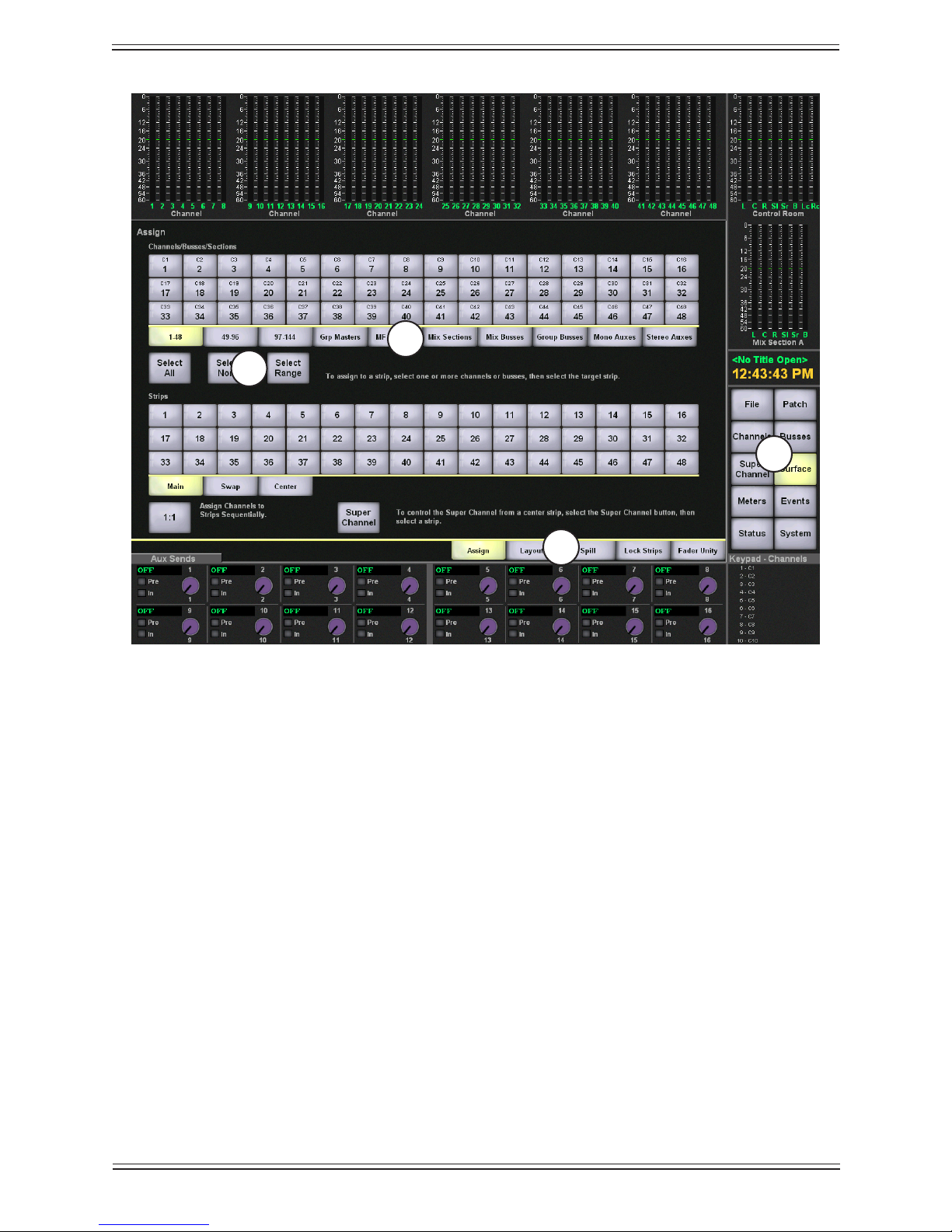
Assign Channels to Strips3.3.2
Touch the 1. Surface menu button on the right side of the screen
Select the 2. Assign tab.
Select the 3. Select Range button.
To assign Channels to Strips:
Select the 4. 1–48 tab beneath the upper bank of buttons called Channels. Select
channels 1–16 from the bank by pressing channel 1 button and then 16.
All 16 channels are selected.
Select the 5. Main tab beneath the lower bank of buttons called Strips. Touch the
Strip 1 button to select and assign the 16 channels in the upper bank to the 16 main
strips on the lower bank.
Select channels 6. 17–32 from the upper bank of channel buttons. Select the Swap
tab beneath the lower bank of strip buttons. Touch Strip 1 to assign channels 17–32
to the rst 16 Swap channels.
The Swap designations light up just beneath the Swap button on each of the rst
16 Strips on the control surface.
To assign MF Masters to Strips:
Select the 7. MF Masters tab from beneath the upper bank of buttons
32
Page 33

Euphonix Max Air Mixing Console Operations Manual Quickstart to Common Tasks
Select MF Masters 8. 1–16 and select the Main tab button beneath the lower bank of
Strip buttons.
Touch the Strip 9. 17 button in the lower bank to assign the rst 16 MF Master to
Main Strips 17–32.
Select MF Masters10. 17–32 and assign them to Swap Strips 17–32.
NOTE: To simply and quickly assign channels 1-x to Strips 1-x, press the 1:1 button.
However, use caution because this overwrites previous assignments!
Busses3.4
Create Main Sections and Audio Subgroups3.4.1
Max Air has 24 individual Main busses that can be grouped into 16 sections labeled
A–H and J–U (I, L, M, N, and O have been omitted to avoid being confused with similar
characters or numbers). Main sections can be setup in the following formats:
mono (M)
stereo (L, R)
LCRS (L, C, R, S)
5.1 (L, C, R, SL, SR, B)
6.1 (L, C, R, SL, SR, SC, B)
7.1 (L, LC, C, RC, R, SL, SC, SR, B)
Main sections can be set to different formats (i.e., A = stereo, B = mono, C =5.1). These
are the Main output busses of the console which can be monitored directly from the control room monitor section. They can also be used as audio subgroups and clean feeds.
Setup Subgroups and Main Program Output
This example creates four stereo subgroups using Main sections A–D and sets the Main
stereo program to Main section E.
Select 1. Busses from the Main Menu buttons.
Select the 2. Main tab at the bottom.
Select the 3. A–H Sections tab beneath the bank of buttons.
Make sure Main busses 1–16 are shown by using the arrows to locate page 1 of 4.
2.
Select Stereo in the Format Selector.5.
Touch Main Bus buttons 6. 1 and 2 in the rst row (Main section A).
33
Page 34

Euphonix Max Air Mixing Console Operations Manual Quickstart to Common Tasks
Touch 7. Set Format to make busses 1 and 2 into a stereo pair assigned to Main sec-
tion A.
The Main Section Master Level control can be mapped to the Soft Knobs just
below the screen by pressing the Main Masters key just below the screen in the
Soft Knobs section. This allows the main section to be switched on/off and level
trimmed.
Assign Main busses 3 and 4 as Stereo to main section B, 5 and 6 to Main section 8.
C, 7 and 8 to Main section D, 9 and 10 to main section E.
Since Main section E is the main stereo program bus, press the E button on the 9.
left and name it Prog in the keyboard popup. Name the other Main sections SubA,
SubB, etc.
34
Page 35

Euphonix Max Air Mixing Console Operations Manual Quickstart to Common Tasks
Placing Main Busses on the Center Section (CM404)
Press the 1. Surface button on the right side of the touch screen and select the “as-
sign” tab. In the upper block, select the Main Sections tab to display the Main/
Mix busses. Select Sections A through E and in the lower Strip block, select the
Center tab. Touch the button representing Center Strip 1 and Main Sections A
through E will be displayed on the rst ve center faders.
Press the 2. Super Channel button on the right side of the touch screen to bring up
the Super Channel page.
On Main Section “A” (SubA), press the 3. Wave key (blue Euphonix logo next to the
fader) in order to display that channel’s parameters and assignments on the Super
Channel.
In the upper left corner of the Super Channel display, press the 4. Setup button in
the Group/Main/Aux assignment box. A pop-up window appears allowing you to
assign that Main (SubA) section to the PGM Section “E”. Take care to not assign
a section to itself: e.g. do not route Main Section A to Main Section A, as feedback
will result.
Once SubA is assigned to PGM, press the wave key on the fader representing 5.
SubB. The assignment pop-up stays open, but now reects SubB’s routing Assign SubB to PGM. Repeat this process for the two remaining sections (SubC and
SubD) and close the assignment pop-up window.
You have now routed your four Sub Sections A-D to the PGM output bus E.6.
Depending on your Mixer Model, it may be desirable to add buss processing (com-7.
pression and limiting) to the output bus and sub sections. Please refer to Chapter
6, pages 111-125 for details on assigning processing to busses.
Figure 3-2
35
Page 36

Euphonix Max Air Mixing Console Operations Manual Quickstart to Common Tasks
Route to the Main Sections and Busses3.4.2
Route Channels
Press 1. All key on center section just below the left of the screen.
Press the 2. Main button at the top of any strip to select Main section routing on all
strips.
The ◄► keys at the bottom of the knobsets allow paging if there are more than four
Main sections.In this case the Prog (Main section E) appears on the 2nd page.
The four Main sections are shown as SubA, SubB, SubC and SubD in each Strip. 3.
To route the channel to SubA, press the On key next to the knob labeled SubA.
The routing LED at the top of the Strip shows the channel is routed to Main section
A. Do this for the rst 16 Strips.
Press any Strip’s 4. Swap button and repeat steps 2 and 3 so that the backup mics
plugged into channels 17–32 are also routed to Main section A.
Using the 24 Group Busses3.4.3
Max Air includes up to 24 Group busses. These are very useful for additional clean feeds
or extra stereo outputs. As an example we could use Groups 1 and 2 as a stereo foldback
output.
Select 1. Busses from the Main Menu and the Group tab.
Check that 1 and 2 are set to stereo. If not select the stereo format from the Format 2.
Selector, select busses 1 and 2, and press the Set Format button.
For mono mix minus, these could be set as mono busses.
To route a channel to these busses, press the 3. Group button at the top of a Strip. The
group pairs show next to the four knobsets.
Press the two buttons below the 1/2 group display next to the top to route the chan-4.
nel to these busses.
The routing LEDS at the top of the channel light to show routing to Groups 1 and
2.
The output level of the groups can be brought up on the Soft Knobs below the 5.
screen by pressing the Group Bus Masters button on the surface just below the
right edge of the Touchscreen.
36
Page 37

Euphonix Max Air Mixing Console Operations Manual Quickstart to Common Tasks
Meters3.5
After channels are assigned to the surface, set the meters to suit your needs.
Setting the Fader Meters On Each Strip3.5.1
We recommend beginning here since you will be able to see signal when you patch into
the channel.
Select 1. Meters from the Main Menu.
Select the 2. Fader tab.
This view shows all available Strips on your Max Air Console.
Touch 3. Select All, then choose Fader in the Meter Display area to the right to en-
able the meter next to each fader on the Strips.
When you begin patching audio into console, you will now see signal on each
channel as you patch.
Screen Meters on the Touchscreen3.5.2
There are eight meter banks across the top and down the right side of the Touchscreen.
You can choose from a wide variety of signals to display here. Since there are meters set
up on every channel, it is probably best to select the screen meter area to display Subgroups, Aux Masters, Solo, and Program. In this example we will place the meters for
these busses on the screen.
Select 1. Meters from the Main Menu.
Select the 2. Screen tab.
Select the left-most meter bank area (selected bank shows a yellow outline box).3.
To select the four stereo subgroup masters we created earlier, press the 4. Main Sec-
tions button in the Function area.
Select Main section 5. A (labeled SubA in the Main Section box).
You will see the SubA stereo meters appear in the selected bank.
Select the adjacent meter bank to the right and repeat above steps until SubA, 6.
SubB, SubC, and SubD meters are visible.
On the fth meter bank from the left, place eight Aux masters:
Select the fth meter bank area from the left.7.
Select 8. Aux Busses from the Function area – the available aux busses buttons ap-
pear on the right area of the screen.
37
Page 38

Euphonix Max Air Mixing Console Operations Manual Quickstart to Common Tasks
Touch the 9. Select Range button in the Aux Busses view. Touch 1, then 8.
This places the rst eight aux meters in the fth bank.
Repeat above steps for the Solo (in 10. Solo Bus), Program (in Main sections by se-
lecting Main section E), and Control Room Meters (in Control Room).
The names that appear below the meters are the names assigned to the busses earlier.
Channel/Strip Metering
You can put channel meters along the top of the Touchscreen. There are 48 meter spaces
available along the top row, not including the right corner section. Note that there are
two options with the Channels and Strips buttons: channels are the actual logical chan-
nels, Strips are the physical position of the Strips on the console. If you set the meters to
show channels, these will not necessarily match what is on the actual console Strips.
When you select the Strips button you will notice that you can set the meters to look
at just the Main or the Swap or whatever is on the Fader by selecting the appropriate
tab below the bank of buttons. If you select Fader, the meters change when you press
the Swap button on a Strip. The meters will read the signal path that is being controlled
by the actual fader. Also note that the position of the meter point in a channel can be
individually set to one of seven positions, so it can meter pre- or post-fader, pre- or postEQ, etc. The position of the meter in the channel signal path can be set by selecting the
Super Channel Main Menu button, then the Setup button in the Process Order box to
the left.
External Meters Display3.5.3
The optional External Meters Display allows the user to view up to 28 additional banks
of meters on an external display. An additional graphics card and 1280x1024 resolution-
capable display is required for this feature.
There are three display modes for the External Meters Display:
None -- only displays the Max Air logo.
3 Rows -- displays three 7-bank rows of meters
4 Rows -- displays four 7-bank rows of meters
To set up the External Meters Display, select Meters from the Main Menu. Select the
Setup tab and choose three or four rows of external meters. Select the Screen tab. Select
the Ext 1 tab. Congure the top 7 banks of meters, selecting what you want displayed
in each bank. (See page 85 to learn how to congure a meter bank.) These 7 banks will
appear as the rst row of banks on the External Meter Display. Selecting the Ext 2, Ext
3 and Ext 4 tabs enable you to set up the second, third, and fourth rows of meter banks,
respectively.
You can also choose different colors for each meter bank. When the bank is highlighted,
select one of the colors from the column on the right side of the popup. The default color
is blue.
38
Page 39

Euphonix Max Air Mixing Console Operations Manual Quickstart to Common Tasks
Knobsets3.6
Knobsets allow users to customize the four rotary controls on the surface to suit their in-
dividual requirements. There are six buttons at the top of each strip (Pan, Filt, EQ, Dyn,
Inp and *) that determine which parameters the knobset controls. In this example, we
will congure the * custom knobsets for mono and stereo channels. From bottom to top,
we will congure mono channels to have mic gain, pan, aux 1 and aux 2. Stereo channels
will have line trim, balance, aux 1 and aux 2.
Creating a Custom Knobset for Mono Channels3.6.1
Select 1. System from the Main Menu.
Select the 2. *Knobset tab.
The * in front of Knobset in the tab indicates that this custom set of knobs is accessible by pressing the * key at the top of each channel strip.
The view shows two boxes, the one on the left is a set of rotary controls and keys 3.
found on the strip. The boxes on the right are buttons that indicate the channel
functions.
Select the bottom box on the left.4.
It highlights yellow to show it is selected.
Select the 5. Input function in the middle column.
The grid on the right shows all input functions of the channel strip.
Select the A input 6. Gain situated in the bottom-left of the bank of buttons.
There are two inputs per channel each with Impedance, 48 V phantom, High-Pass
Filter, Mic Gain, digital input Trim, and Phase controls. The Delay settings and the
Input key (between the A and B Inputs) are common to both inputs. Note that the
Impedance, 48 V phantom, High-Pass Filter, and Mic Gain controls appear only
on channels that have been connected to a Mic Preamp (Channels 1–24 in the example at the beginning of the Quickstart).
You have just congured the Mic Gain control to appear on the bottom control on
the channel strip when the * key is selected on any strip.
Repeat the above steps choosing Pan F (Front pan) for the panner and Aux 1 and 7.
Aux 2 for the auxes. From bottom to top the four knobs will show Mic Gain, Pan,
Aux 1 and Aux 2.
By paging to the next set of knobs using the arrow keys at the top you can set a 8.
total of 16 custom knobs.
39
Page 40

Euphonix Max Air Mixing Console Operations Manual Quickstart to Common Tasks
Creating a Custom Knobset for Stereo Channels3.6.2
Select System from the Main Menu.1.
Select the 2. *Knobset tab.
Scroll to Page 2 using the arrow button on the top-left.3.
Select the bottom area in the left box.4.
It highlights yellow to show it is selected.
Select the 5. Input function in the middle column.
The grid on the right shows all input functions of the channel strip.
Select the A input 6. Atrim
Select the second knob area on the left and select 7. Input, then Balance.
Repeat for the other knobset positions choosing Aux 1 and Aux 2.8.
External Device Setup3.7
Max Air includes up to 32 external inputs that can be directly monitored at the touch of
a button. These individual inputs need to be grouped together, assigned a format, named
and attached to External Device buttons to match the external sources (i.e., Off Air Stereo, Dolby E Decoded 5.1, CD player, etc.).
Patching External Devices into the External Inputs3.7.1
Decide the sources to be patched into external inputs. For example, the rst 24 digital
sources coming into the console that we labeled Digital In 2 are external sources.
Select 1. Patch from the Main Menu.
Select the 2. Sources tab.
Select the fourth gray button which should now be labeled 3. Digital In 2.
Select the 4. 1–32 tab.
Touch and drag through the green 5. Digital In 2 column to select the rst 24 sourc-
es.
These appear in the green Sources list to the right.
Select the 6. Console I/O tab and select the Externals button on the left.
Touch and drag through the blue 7. External column to select all 24 External in-
puts.
Touch the8. Patch Selected button to make the patch.
40
Page 41

Euphonix Max Air Mixing Console Operations Manual Quickstart to Common Tasks
The rst 24 devices coming into the fourth MADI input (in this case the second Digital
Format Converter) are patched to the 24 External Inputs of the console. Note that it is
also possible to patch these into channels: the router allows any patch output to be sent
to more than one source.
Assign External Inputs a Format and a Button3.7.2
Select 1. System from the Main Menu.
Select the 2. Externals tab.
Select 3. Sets 1–8
Set the format to 4. Stereo L R.
To assign Ext Mon Inputs 1 and 2 to Device 1 button as a stereo pair, touch the 5.
buttons labeled 1 and 2 in the rst row and touch Set Format.
Touch the 6. Device 1 button on the far left and name the device Off Air.
Repeat the steps above for all externals.7.
The system allows any combination of formats. For example, a 5.1 Dolby E monitor set
of six inputs could be assigned as a 5.1 format to device button 2.
NOTE: Regarding 5.1 formatting: Euphonix’ 5.1 formatting follows the post produc-
tion convention of L, C, R, SL, SR, and B (or LFE). If you choose to have the
channel order match that of the Dolby E format (L, R, C, LFE, Ls, Rs) you
can either cross-patch to the correct channels or proceed as follows to make
a 1:1 channel order. Select the rst two external input channels of the device
in question, select “5.1” in the Format Selector and then DE-select the C, SL,
SR, B buttons within the Format Selector itself. Hit “Set Format” and the rst
two channels are now 5.1L and 5.1R. De-select these two channels and select the adjacent pair. In the Format Selector box, de-select L & R and choose
C and B instead. Hit “Set Format”. The next two external input channels are
now 5.1C and 5.1B (a.k.a. LFE). De-select these two external input channels
and select the next two adjacent. In the Format Selector box, se-select C &
B and choose SL and SR instead. Hit “Set Format”. The last pair of external
input channels are now formatted to be SL and SR (or Ls, Rs, if you prefer)
and you have a true Dolby formatted 5.1 input which can be patched 1:1 from
the output of the decoder or monitoring tool.
41
Page 42

Euphonix Max Air Mixing Console Operations Manual Quickstart to Common Tasks
Externals Main Sections Aux Snds
CR
Monitors
8 Out (max 7.1)
Mon A
8 Out (max 7.1)
Alt 2
Stereo
Alt 1
6 Out (Max 5.1)
Main
8 Out (max 7.1)
Mon B
Stereo
Mon C
Stereo
Mon D
Stereo
Monitor Selector
Rtn
Out
Monitors3.8
Setting up the monitors is the nal step to getting sound to the speakers. Note that only
certain monitor outputs can handle surround outputs.
Control Room Monitors
Press the 1. Setup button in the Control Room Monitor area of the Super Channel on
the surface.
Select the 2. CR Source tab.
Select the appropriate source from the screen.3.
In our example the fth Main section should be labeled Prog and has the main
program output.
The three buttons labeled Main Spkrs, Alt 1, and Alt 2 allow using three different
speaker sets in the control room.
Monitor A–D
The four speaker sets labeled Mon A–D can be used for additional monitoring including
green room feeds, oor foldback, etc. Setup is simple: press the Setup button at the top-
right of the Super Channel section to bring up the source options for these monitors.
Monitor RoutingFigure 3-3
42
Page 43

Euphonix Max Air Mixing Console Operations Manual Quickstart to Common Tasks
Save a Default Title3.9
Once you have completed this setup process, you should save this Title.
Touch the 1. File menu button and select the Title tab.
Touch the 2. Save button in the Current Title box to save all the changes you have
made. Do this frequently when making changes.
If you touch the 3. Save As Default button, the current settings will become the de-
fault settings and will be loaded when a new Title is created.
WARNING: Do not do execute step 3 if your technical or operational department has al-
ready set up the console and saved a Default Title.
43
Page 44

Euphonix Max Air Mixing Console Operations Manual Quickstart to Common Tasks
44
Page 45

Euphonix Max Air Mixing Console Operation Manual
TouchscreenChapter 4:
Introduction to the Touchscreen4.1
The Max Air Touchscreen allows you to touch items on the screen that you would normally click with a mouse. The software can still be operated with a mouse and keyboard
but we will conne our instructions to the “touch” interface because most users are unfamiliar with it. The main difference between a touch and conventional interface is that
there is no “double-touch” corresponding to a double-click to launch or open an item.
The term View is used for a screen of information that is activated by touching a menu
button or tab. There is no Close button to a View. Change Views by selecting another
View.
The term Popup is used for a window of topical information that is opened by touching
a button and closed by touching a Close button. A Popup is similar to a dialog box in
other systems.
When a keyboard popup is presented to name something (Figure 4-1), either touch the
letters onscreen or type them on the system computer keyboard. Either touch the Enter
button onscreen or hit the Enter key on the system computer keyboard.
Keyboard PopupFigure 4-1
We will use the word select to refer to items that stay selected or illuminated when
touched, or that activate a new mode.
We will use the word touch to refer to items that are activated when touched but do not
persist or activate a new mode.
45
Page 46

Euphonix Max Air Mixing Console Operation Manual Touchscreen
The Max Air Touchscreen application has 10 Main Menu buttons along the right side of
the screen that access its functions:
Touchscreen Main Menu ButtonsFigure 4-2
File:• le management
Patch:• digital patchbay
Channels: • congure Multi Format Masters, assign and name Control Groups,
congure Snapshots.
Busses:• congure and assign group, main, and aux busses
Super Channel:• shows all settings of the Super Channel
Surface:• assign channels to Strips, congure Layouts, assign Spill to Strips, lock
Strips, and set faders to unity gain.
Events:• GPI/O event conguration and Scene Automation operations
Meters:• congure meters and meter presets
Status:• view the status of any installed module; also performs some diagnostic
functions
System:• congure external monitor inputs, congure custom knobset, view Mixer
Model, and set Preferences
46
Page 47

Euphonix Max Air Mixing Console Operation Manual Touchscreen
1
4
2
5
3
Touchscreen Main ViewFigure 4-3
Four important types of information are displayed on the Touchscreen:
Permanent Display• : Consists of the Soft Knobs Display (3), the Main Menu but-
tons (5), a Keypad Function Viewer (6) and a display of the current Title and Time
of Day Clock (4).
Meters (1)• : The area at the top and upper-right of the display is used for level
meters.
View Area (2)• : The majority of the screen area between the meters and the perma-
nent display is used for context-sensitive Views.
Popups• : These are like dialog boxes used for a specic task (i.e., oscillator pa-
rameters, keyboard, etc.) that remain on screen until their task is completed or
canceled.
6
47
Page 48
Euphonix Max Air Mixing Console Operation Manual Touchscreen
3
4
1
2
Touchscreen NavigationFigure 4-4
Views are selected from the Main Menu buttons on the right side of the screen (1). Several views have multiple sub-views accessed by tabs (2). Within a view, Ranges Tabs (3)
select additional values and Screen Buttons (4) control various functions.
48
Page 49
Euphonix Max Air Mixing Console Operation Manual Touchscreen
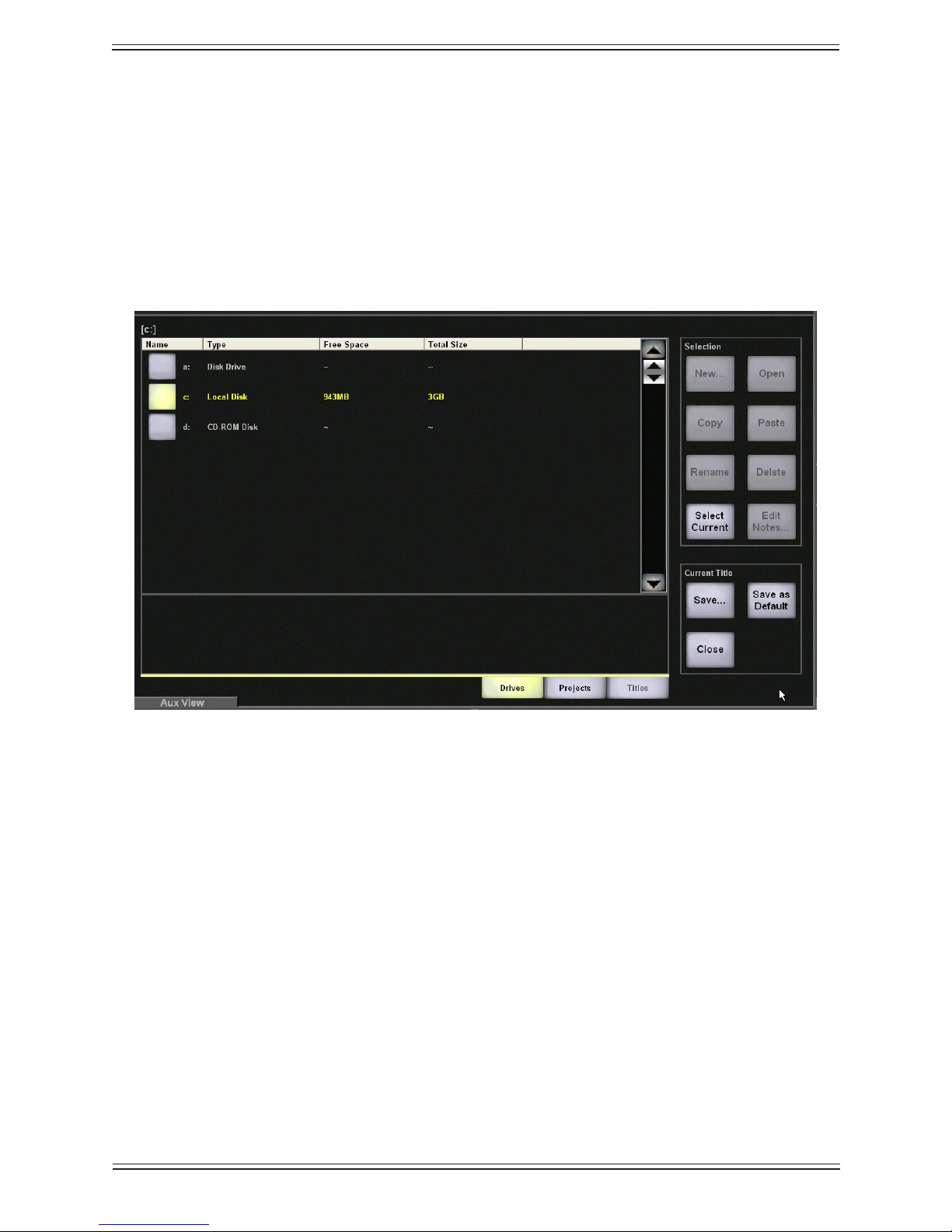
File4.2
Select the File button to navigate the Max Air le system. Three tabs along the bottom
of the view list the main subjects: Drives, Projects, and Titles. The order of these tabs
also represents their hierarchy (i.e., a Title is within a Project located on a Drive). File
operations are almost identical to those in Windows or the Macintosh, where a “drive” is
the actual storage Media (here, the “C:” drive is the RAID1 system drive and is generally
the preferred drive for your on-line project and title storage), Project is the equivalent of
a “folder” and a Title is the actual le itself..
Drives ViewFigure 4-5
Select the Drive on which to begin a new Project or open an existing Project. The Drive
name highlights but the Open button is dim because it is not necessary to open the drive;
just select the Projects tab to nd the project to open on that Drive.
Projects4.2.1
Select the Projects tab to view the Projects on the selected Drive. A Project must exist
before you can create a Title. A Project is essentially a folder in which Titles are stored.
49
Page 50

Euphonix Max Air Mixing Console Operation Manual Touchscreen
Projects ViewFigure 4-6
Create a New Project
Touch the New button in the Selection area along the right side of the Projects View.
Type a name in the view that appears and touch Enter.
Open an Existing Project
Select a Project name. The name highlights and there is no need to touch the Open button for the Project (since it is dim, you cannot). Just touch the Titles tab to see the Titles
within the selected Project (see Titles on page 51 to learn how to open a Title).
Rename, Copy, Paste, or Delete Project
The Rename, Copy, Paste and Delete buttons are located in the Selection area on the
right side of the Projects View. The easiest way to backup a Project is by copying and
pasting it to another Drive.
50
Page 51

Euphonix Max Air Mixing Console Operation Manual Touchscreen
Select a Project from the Projects View.
Touch the • Copy button to copy the selected Project.
The Paste button remains dim until the Copy button is used. Note that you cannot
copy a project to a CD-RW or CD-R drive from the application.
Touch the • Paste button to paste the copied Project. Of course, you can navigate to
another Drive before pasting.
If the selected Project’s name is Test, the copied Project is Copy of Test.
Touch the • Rename button to rename the selected Project in the keyboard popup
that appears. Touch Enter to complete the process or Cancel to leave the name
unchanged.
Touch the • Delete button to delete the selected Project.
The Project is deleted and cannot be pasted.
Titles4.2.2
A Project must exist before selecting, opening, or creating a new Title. The Rename,
Copy, Paste, and Delete buttons work the same on Titles as described above for Proj-
ects.
To open or create a Title, a Project must rst be selected (see Projects on page 49).
Titles ViewFigure 4-7
51
Page 52

Euphonix Max Air Mixing Console Operation Manual Touchscreen
Create New Title
Touch the New button in the Selection area along the right side of the Titles View. Type
the Title name in the New Title Name View that appears. Touch Enter to complete the
process or Cancel to exit without creating the Title. The following popup appears:
Save Current Data PopupFigure 4-8
Yes• : Saves the settings from the current title into the new title.
No• : Uses settings for Default Title to reset console. See page 53 to see how to
change the default settings.
Open Existing Title
Select the Title name and touch the Open button in the Selection area.
Operations on the Current Title4.2.3
Current Title ButtonsFigure 4-9
The three buttons in the Current Title area provide an easy way to operate on the currently open Title from any File view. They are dim if a Title is not open.
Save• : Performs both regular Save and Save As functions. A keyboard popup ap-
52
Page 53

Euphonix Max Air Mixing Console Operation Manual Touchscreen
pears with the current Title’s name in the edit box. Touch Enter to save changes to
the current Title. Save a copy under a different name by typing a new name. The
new Title becomes the currently open Title.
Save as Default• : Uses the settings in the current Title for new Titles. See Default
Titles on page 51 for more information about what is saved.
Close• : Prompts you to save changes before closing the current Title.
Select Current
Touch the Select Current button to instantly navigate back to the currently open Title in
the Titles View. This is a convenient way to browse the File system without losing your
place.
Edit Notes
Touch the Edit Notes button to enter any information about the Title. The notes are displayed below Title names in the Title View.
Default Titles4.2.4
The settings stored in the Default Title are automatically included with each new Title.
Each Mixer Model has a Default Title le. The following settings are contained in the
Default Title:
Patch settings and names•
Bus Setup: names and formats•
Externals Setup: names and formats•
SnapShots•
Layouts•
Meter setups•
NOTE: The Default Title is a le on the System Computer but does not appear in the
Directory.
Setting the Default Title
The Default Title can be set by touching the Save As Default button in the Titles View.
This copies all settings listed above from the currently open Title into the Default Title
for the current Mixer Model. A warning view appears to conrm this action.
53
Page 54

Euphonix Max Air Mixing Console Operation Manual Touchscreen
MC524
Monitor Interface
MA703
MADI to Analog
DSP
Core
MA703
Analog
AM713
Analog
ML530
Analog Mic/Line
AM713
Analog
DM714
Digital
Ta lk & Listen
Mics
Speakers
System
Computer
MD704
Digital
FC727
Digital
FC727
Digital
Modular I/O
Mixed
Patch4.3
The Patch View allows connections between the console and external devices in exactly
the same way as a conventional analog patchbay. The most signicant difference is that
patches can be created then saved and recalled with the Title.
The Patch View implements a digital patching system that uses a MADI routing hub to
connect sources to the console and its destinations.
Simplied MADI routing diagramFigure 4-10
The following devices provide a robust and complete I/O interface:
The Euphonix DM714 (AES/EBU-to-MADI) and MD704 (MADI-to-AES/EBU) •
converters provide 26 channel inputs and outputs.
The Euphonix AM713 (analog-to-MADI) and MA703 (MADI-to-analog) provide •
24 xed-gain channel inputs and outputs.
The Euphonix ML530 provides 24 remote, variable gain, analog, mic/line pre-•
amps that can be controlled from the Strip.
The Euphononix FC727 and FC726 provide 56 channels of digital format conver-•
sion.
The Euphonix Modular I/O provides up to 56 mixed-format (see page 26) channel •
inputs and outputs.
Some equipment, such as the Euphonix R-1, the Sony 3348HR recorder, DAW’s and
some high end consoles, offer a MADI interface. Most equipment, however, (i.e., mics,
speakers, and vintage gear) must convert to and from MADI using the appropriate Euphonix converter.
54
Page 55

Euphonix Max Air Mixing Console Operation Manual Touchscreen
Sources
Max Air Console
Destinations
Max Air must be initially setup so that all the studio equipment is displayed and correctly labelled and normalled ready for a session. This basic wiring information is stored
in the Default Title so these settings can be used when starting a new session with a new
Title. To setup Max Air studio wiring, see Chapter 3: Quickstart to Common Tasks.
Select Patch from the Main Menu buttons. The Patch View has four categories represented by tabs on the bottom of the screen: Console I/O, Destinations, Sources, and
Cabling.
Destinations and Sources4.3.1
Figure 4-11 shows that sources and destinations refer to the Max Air console. Sources
are signals sent to the console (i.e., signals from the analog to MADI and digital to
MADI converters, microphones, tape/VTR outputs). Destinations are signals sent from
the console (i.e., signals sent to the MADI to digital converters, VTR inputs).
Sources and Destinations with respect to Max AirFigure 4-11
A fully-loaded DF66 will have 24 MADI device input ports and 23 output ports on the
console, each carrying up to 64 channels. The smallest DF66 conguration will have 8
MADI device input ports and 7 output ports available.
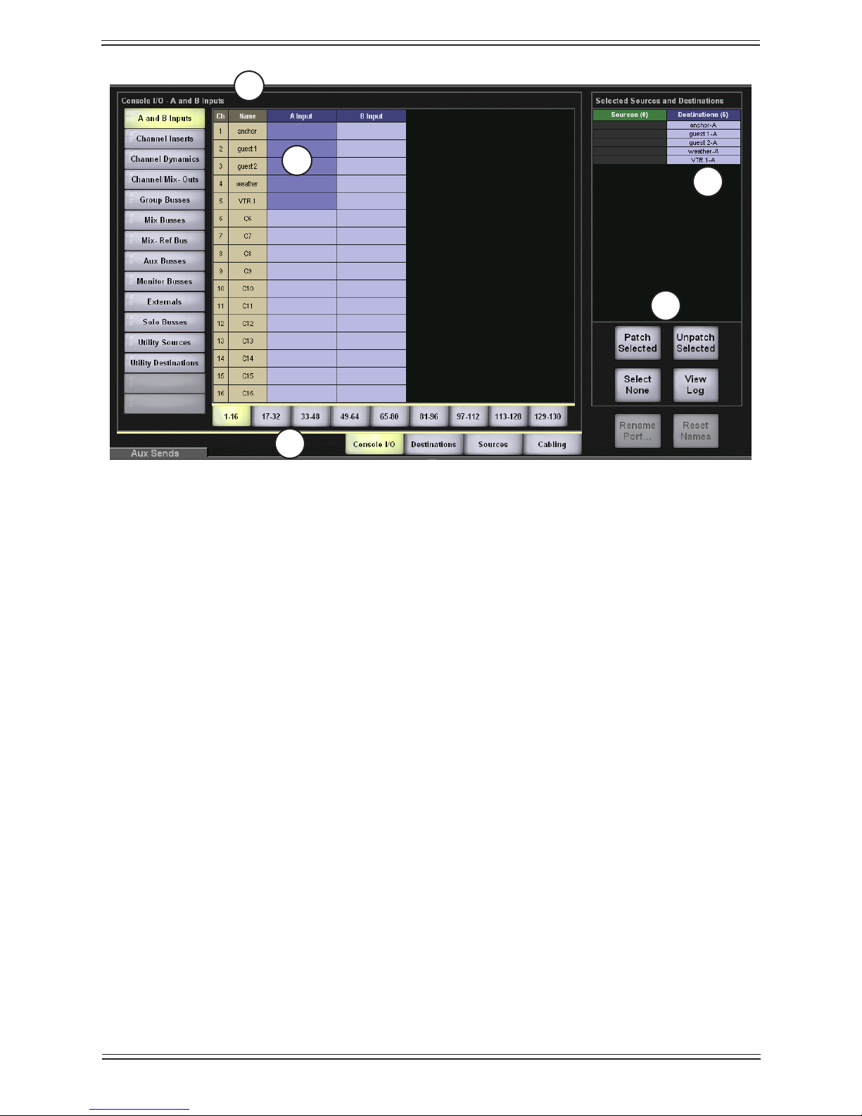
Console I/O4.3.2
Select the Console I/O tab on the bottom of the Patch View, then select the A and B
Inputs sub-category on the left (Figure 4-12). This is where connections to the channel’s
A and B inputs are made. Touch the Name eld (1 in Figure 4-12) and type a name for
a channel.
Touch and drag through the A Input cells (2 in Figure 4-12) for which you would like to
assign a patch. Figure 4-12 shows the result of selecting the A Input cells for channels
1–5. Note that the channel names appear in the Destinations column (3 in Figure 4-12)
in the Selected Sources and Destinations area. The numbered tabs (4 in Figure 4-12)
display additional pages of patchpoints.
55
Page 56
Euphonix Max Air Mixing Console Operation Manual Touchscreen
1
2
3
5
4
Console I/O -A and B Inputs ViewFigure 4-12
The four buttons (5 in Figure 4-12) on the lower-right perform the following functions:
Patch Selected• : Patches selected patchpoints (3 in Figure 4-12)
An error message appears if the sources are not properly matched to the destina-
tions. There must be an equal number of sources and destinations or one source to
multiple destinations.
Unpatch Selected• : Unpatches selected patchpoints
Select None• : Deselects all patchpoints
View Log• : Shows a log of failed patches
56
Page 57

Euphonix Max Air Mixing Console Operation Manual Touchscreen
To complete this Patch example:
Select the 1. Sources tab (1 in Figure 4-13).
Touch and drag through the rst ve cells in the Frame 1-1 column (2 in Figure 2.
4-13).
Note that these names appear in the Sources column of the Selected Sources and
Destinations area next to their counterparts in the Destinations column (3 in in
Figure 4-13).
2
3
4
1
Sources and Destinations SelectedFigure 4-13
Touch the 3. Patch Selected button (4 in Figure 4-13) to make the Patch.
Note in Figure 4-14 that the Selected Sources and Destinations area is cleared (1
in Figure 4-14) and the A Input names appear next to their source channels (2 in
Figure 4-14).
57
Page 58

Euphonix Max Air Mixing Console Operation Manual Touchscreen
2
1
Patch CompleteFigure 4-14
Router Mnemonics
Max Air supports importing router mnemonics to name channels. See page 72 to enable
this feature in Preferences.
NOTE: This function will only work as described if the console has been integrated
with the router system as described in the Max Air Installation Guide.
To enable importing of names to channels, enter “%X” as the Source Input name on the
Touchscreen. “%” indicates that the input is a router input or output. “X” indicates the
number associated with that router destination (console input).
58
Page 59
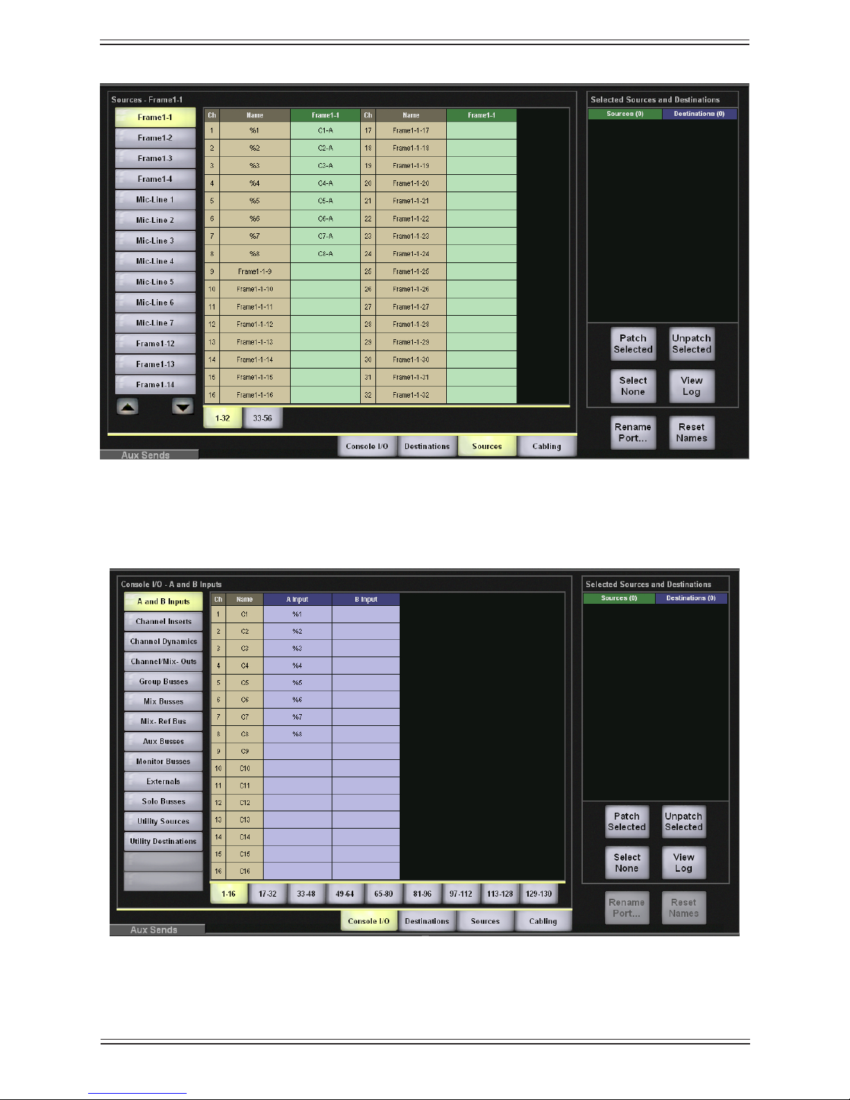
Euphonix Max Air Mixing Console Operation Manual Touchscreen
Source input namingFigure 4-15
The channel displays on the console surface are updated as the names associated with
the sources patched to the channels are changed and sent from the router.
Sources patched to channelsFigure 4-16
59
Page 60

Euphonix Max Air Mixing Console Operation Manual Touchscreen
Cabling4.3.3
This category handles MADI cable connections for the ML530 Mic/Line Interfaces.
NOTE: The following ML530 cabling and patching operations also apply to the Modu-
lar I/O remote-controlled preamp. Each Modular I/O frame can contain from
4 to 32 preamp channels.
Mic/Line Interface Patching
For mic inputs and analog inputs not at +4 dB, the Euphonix ML530 provides 24 preamps
each with gain, phantom power, high-pass lter, and hiz/loz switching. The ML530’s
analog outputs are connected to an AM713 Analog to MADI converter which then connects to one of the MADI inputs.
The patch system must be informed which MADI input each ML530 connects to so their
input controls appear on the corresponding input channel knobset. Note how each Mic/
Line Interface is connected.
In the example that follows, the MADI output from the Analog to MADI converters
of two ML530 Mic/Line interfaces have been connected to the inputs of Frame1-1 and
Frame1-2.
NOTE: We recommend patching each ML530 channel to only one channel input.
60
Page 61

Euphonix Max Air Mixing Console Operation Manual Touchscreen
Select the 1. Cabling tab (1 in Figure 4-17).
Select the 2. MADI Out Ports sub-category (2 in Figure 4-17).
The list shows seven Mic/Line Interfaces but congure only those wired to the
DF66 (i.e., Mic1 and Mic2).
Touch and drag through the cells next to Mic1 and Mic2 in the 3. MADI Out column
(3 in Figure 4-17).
The cells highlight green and the names appear in the Sources column of the Se-
lected Sources and Destinations area (4 in Figure 4-17).
3
2
4
1
Cabling: MADI Out PortFigure 4-17
Select the 4. MADI In Ports sub-category (1 in Figure 4-18).
Touch and drag through the cells to the right of the two Frame1 inputs Frame1-1 5.
and Frame1-2 (2 in Figure 4-18).
The cells highlight green and the names appear in the Destinations column of the
Selected Sources and Destinations area (3 in Figure 4-18).
61
Page 62

Euphonix Max Air Mixing Console Operation Manual Touchscreen
1
2
3
4
Cabling: MADI In PortFigure 4-18
Touch the6. Patch Selected button (4 in Figure 4-18) to make the patch.
The Patch system now knows how the two mic/line interfaces are connected so the
proper input controls appear at the top of the channels they are connected to.
Because Frame1-1 and Frame1-2 have been designated as MADI connections to the
Mic/Line interfaces, touching Frame1-1 and Frame1-2 in Sources shows Device Patch
in the rst 24 cells and will not allow selection unless they are unpatched.
62
Page 63

Euphonix Max Air Mixing Console Operation Manual Touchscreen
Patching Examples4.4
These examples assume that the steps in Mic/Line Interface Patching on page 58 have
been successfully completed.
Patch 12 Mics Into Channels 25–364.4.1
Select the Sources
Select the 1. Sources tab (1 in Figure 4-19).
Select Mic-Line 1 from the sub-categories (2 in Figure 4-19).2.
This displays all inputs from the rst Mic-Line Interface in the Name column. The
Mic-Line Interface is connected as part of the initial studio setup.
Select Mic1-1–Mic1-12 from the 3. Mic-Line column by touching and dragging
through the cells (3 in Figure 4-19).
These entries are highlighted in green in the Sources column of the Selected
Sources and Destinations area (4 in Figure 4-19). If there were more than 24
sources, additional tabs would appear to the right of the 1–24 tab.
2
3
4
1
Sources View with 12 Mic-Line Sources SelectedFigure 4-19
63
Page 64

Euphonix Max Air Mixing Console Operation Manual Touchscreen
Select the Destinations
There can be:
one source to one destination;•
an equal number of sources to destinations;•
one source to multiple destinations.•
Multiple sources cannot be routed to one destination.
To set the destinations for the 12 mics:
Select the 4. Console I/O tab (1 in Figure 4-20), then select the A and B Inputs sub-
category (2).
Select the 5. 17–32 tab to display those channels.
Select channels 25–32 by touching and dragging through the 6. A Input column next
to C25–C32.
Select the 7. 33–48 tab to display those channels.
Select channels 33–36 by touching and dragging through the 8. A Input column next
to C33–C36 (3 in Figure 4-20).
The entries are highlighted in green and the list of A input channels appears in the
Destinations column in the Selected Sources and Destinations area (4 in Figure
4-20).
64
Page 65

Euphonix Max Air Mixing Console Operation Manual Touchscreen
2
3
4
5
1
Selecting Destination ChannelsFigure 4-20
Click the 9. Patch Selected button (5 in Figure 4-20) to make the connection.
The sources and destinations appear in the A Input and Name columns, respectively (1 in Figure 4-21). The sources and destinations are cleared from the Se-
lected Sources and Destinations area (2 in Figure 4-21).
2
1
Mic Patch CompleteFigure 4-21
65
Page 66

Euphonix Max Air Mixing Console Operation Manual Touchscreen
Patch the Multitrack Returns Into Channels 1–24
Select the1. Sources tab (1 in Figure 4-22).
Select the 2. Frame1-3 sub-category (2 in Figure 4-22).
Touch and drag through the rst 24 cells in Frame1-3 column (3 in Figure 4-22).3.
These cells are highlighted and their names appear in the Sources column in the
Selected Sources and Destinations area on the right (4 in Figure 4-22).
2
4
3
1
Sources SelectedFigure 4-22
Select the4. Console I/O category.
Select the 5. A and B Inputs sub-category.
Touch and drag through the rst 24 cells in the 6. A Input column.
These cells are highlighted and their names appear in the Destinations column in
the Selected Sources and Destinations area on the right.
Touch the 7. Patch Selected button to make the connection.
The sources and destinations appear in the A Input and Name columns, respec-
tively (1 in Figure 4-23). The sources and destinations are cleared from the Se-
lected Sources and Destinations area (2 in Figure 4-23).
After connecting the 12 mics and the R-1 returns, the Console I/O A and B Inputs
View is shown in Figure 4-23.
66
Page 67

Euphonix Max Air Mixing Console Operation Manual Touchscreen
2
1
R-1 and Mics PatchedFigure 4-23
Main Bus Send/Return4.4.2
Select the Console I/O category and then select the Main Busses sub-category. Each
Main bus has a send and return. Figure 4-24 shows the rst six sends (a 5.1-channel
Main section) routed to channels 41–46 A inputs. The insert is switched in/out from the
Bus Masters Cong Page (see Bus Inserts on page 122).
Main Bus Send and ReturnFigure 4-24
67
Page 68

Euphonix Max Air Mixing Console Operation Manual Touchscreen
For every Main section, there is a corresponding return in the same format, which allows
patching the Main section recorder output back into the console. The Main section return
can be routed to the monitors from the Main Section page in the CR Source Panel (see
Control Room on page 129).
Monitor Patching4.4.3
The monitor outputs are automatically routed to the analog patch unit supplied with Max
Air and are ready to be normalled to the speaker inputs. The monitor feeds are also available within the Patch View for routing to other destinations if necessary.
Select the Console I/O category and the Monitor Busses sub-category. This window
shows all 22 monitor feeds:
Monitor BussesTable 4-1
Monitor Busses Format
1-8 Control Room L, C, R, Sl, Sr, Bm, X, Y
9-16 Mon A L, C, R, Sl, Sr, Bm, X, Y
18-18 Mon B L, R
19-20 Mon C L, R
21-22 Mon D L, R
The Cascade inputs allow for direct bus injection prior to the insert point into all monitor
signal paths.
Solo Bus and Utility Patching4.4.4
The Solo Busses sub-category in Console I/O allows custom patching of the stereo Solo
Bus. There is an Insert Send, Insert Return and separate solo output available for patch.
The Utility Sources sub-category includes the Oscillator output. The Utility Destina-
tions sub-category includes the Slate In which must be patched to the Talkback mic feed
from the Monitor Interface.
Talkback Signal Patching4.4.5
The talkback mics are wired to the MC524 Monitor Controller. They are amplied to
produce a single talkback signal. This analog signal must be fed into the system through
an Analog to MADI converter.
To send talkback to the busses, this signal must be patched to the Slate-TB Input (in the
Utility Destinations subcategory of the Console I/O category). Note which analog to
MADI converter input the talkback signal has been patched to and connect that channel
to the Slate-TB Input.
68
Page 69

Euphonix Max Air Mixing Console Operation Manual Touchscreen
Busses4.5
See Chapter 6: Busses.
System4.6
The System View has ve tabs: Externals, *Knobset, Mixer Model, Preferences, and
About.
Externals4.6.1
Select the Externals tab from the System View to congure the Externals in the same
way as Main and Group busses.
Externals ViewFigure 4-25
69
Page 70

Euphonix Max Air Mixing Console Operation Manual Touchscreen
*Knobset4.6.2
Select the *Knobset tab from the System View. The *Knobset View allows a customized set of 16 knob parameters to be displayed on the Strip when the channel’s * key is
pressed at the top of the Strip.
1
4
3
2
*Knobset ViewFigure 4-26
Select the page (1 in Figure 4-26) and knob position (2) for the function parameter 1.
from the Custom (*) Knobset area on the left.
Select a 2. Function from the center of the View (3).
Select the parameter from the 3. Function Parameters section on the right (4).
Repeat for each of the four knob positions and pages.4.
The Fader button can be used to put the Swap channel’s fader on a knob. This can provide simultaneous control of the Main and Swap fader level controls.
70
Page 71
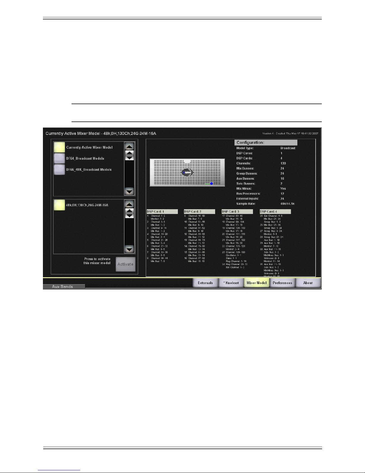
Euphonix Max Air Mixing Console Operation Manual Touchscreen
Mixer Model4.6.3
Select the Mixer Model tab from the System View. Max Air currently supports three
types of Mixer Models: DF66, DF 64 with a Studio Hub, and a DF64 without a Studio
Hub. To activate a different Mixer Model, touch the Max Air Models button on the left
of Figure 4-27. The two Mixer Models are displayed in the area below. Select the desired
Mixer Model and touch the Activate button.
NOTE: A complete system restart is required after activation of a Mixer Model.
Mixer Model ViewFigure 4-27
71
Page 72

Euphonix Max Air Mixing Console Operation Manual Touchscreen
Preferences4.6.4
Select the Preferences tab from the System View.
Preferences ViewFigure 4-28
Knob Text Display Mode
The Knob Text Display Mode buttons intercancel between three values:
Show value when touched, name otherwise• : Displays the value of the knob pa-
rameter when touched and reverts to the name afterwards.
Always show name• : Displays the parameter name even when touched.
Always show value• : Displays the parameter value even when touched.
Fader Text Display Mode
The Fader Text Display Mode buttons intercancel between the same three values de-
scribed above but the setting applies to touching the faders instead of knobs.
72
Page 73

Euphonix Max Air Mixing Console Operation Manual Touchscreen
Safety
The Safety section includes two buttons that can be set independently:
Bus Lock• : Disables the following functions when activated: Bus Levels (Main
Master, Master Trims, and Leg Trims), Bus Inserts, Bus On/Off keys.
While these functions are disabled, their values may still be interrogated.
Monitor Lock• : Disables the Control Room and Monitor levels. Dim and Cut
always remain active.
Clock Source
The on-screen clock can be set to Internal or External.
Select External to synchronize to a facility “Time of day” type clock using LTC.
Connect LTC to the LTC input of the system MIDI interface.1.
From the 2. Main Menu, press System.
Set the 3. Clock Source to External.
Select the desired display format from 4. Clock Display Format.
Clock Display Format
Allows the clock to be displayed in three formats: 12, 24 hour, HH:MM:SS:FF.
Delay Display Format
Allows the delay time units to be displayed in three formats: samples, frames, or seconds
Misc
Group Bus as Mix Minus: Activating this button inverts the group bus assignment indicators so channels NOT assigned to the bus are lit.
Show Router Names: This enables the router mnemonics feature (see page 58).
About4.6.5
Select the About button in the lower-right corner of the System View to display software
version information and a Shutdown button. Touching the Shutdown button does not
prompt you to save changes, so be sure to save before exiting the program (see Operations on the Current Title on page 52). You can also use the keystrokes Ctrl-Alt-* simul-
taneously. The * is from the numeric keypad not Shift-8.
73
Page 74

Euphonix Max Air Mixing Console Operation Manual Touchscreen
Channels4.7
Select Channels from the Main Menu buttons. There are seven views that are accessed
by tabs along the bottom of the screen.
Figure 4-29 Channels Tabs
Multi Format Masters4.7.1
See Chapter 8: Control Groups and Multi Format Masters.
Control Groups4.7.2
See Chapter 8: Control Groups and Multi Format Masters.
Surface4.8
Select Surface from the Main Menu buttons. There are ve views that are accessed by
tabs along the bottom of the screen.
Figure 4-30
Assign4.8.1
Select the Assign tab from the Surface View to assign channels to strips in the Assign
View (Figure 4-31 shows the Assign View with channels 1–8 selected).
74
Page 75

Euphonix Max Air Mixing Console Operation Manual Touchscreen
Assign ViewFigure 4-31
Select the channels to assign by touching them individually, touching and dragging
through a continuous set, or by using the three utility buttons (Select All, Select None,
Select Range) on the bottom-left of the Assign View (see below for a discussion of these
buttons). Select the Main, Swap, or Center tabs to assign the channels to the desired strip
type.
Touch a single strip to assign the selected channels sequentially from that strip upwards.
If the channels are not contiguous (i.e., 2–3, 5), they will still be assigned to sequential
strips, even if some of the strips already have channel assignments.
To control the Super Channel from the Center Strip, select the Super Channel button
and select a strip.
Touch the 1:1 button to assign channels 1–48 to Strips 1–48 Main.
Select Range
Use the Select Range button at the bottom-right of the Assign View to select a channel,
then select a higher or lower numbered channel to select all channels in between. The
range can include channels in another tab (i.e., C25–C55, C15–M25). The range is set
by each pair of selections.
When a channel is selected in a tab other than the selected tab, that tab highlights dimly
around the edges. In the gure below, 49–96 is the selected tab but channels are also
selected in 1–48.
75
Page 76
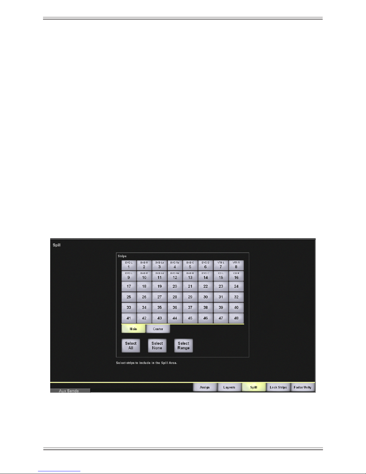
Euphonix Max Air Mixing Console Operation Manual Touchscreen
Select All
Use the Select All button to select all channels across all tabs (1–48, 49–96, Grp Masters, and MF Masters).
Select None
Use the Select None button to deselect all selected channels.
Layouts and Snapshots4.8.2
See Chapter 9: Layouts and Snapshots.
Spill Area4.8.3
Spill allows Control Groups and Multi Format Masters to spill their slaves to a dened
area so they can be individually accessed. See Spill on page 153 for details.
To create a Spill area:
From the 1. Main Menu, press the Channels button.
Select the 2. Spill tab.
Select the strips to include in the Spill area.3.
Spill Area functionFigure 4-32
76
Page 77

Euphonix Max Air Mixing Console Operation Manual Touchscreen
Lock Strips4.8.4
Select the Lock Strips tab to display the Lock Strips View (Figure 4-33), which provides the ability to prevent strips from being affected by Layout recall.
Lock Strips ViewFigure 4-33
Select one or more Strips to lock. Use the Main and Center tabs to select the strip type
(Main locks both Main and Swap). Use the Select All, Select None, and Select Range
buttons (see page 76) to assist your selection. There is no Close button; just select another view and this information is retained.
Fader Unity4.8.5
Select the Fader Unity tab to display the Fader Unity popup (Figure 4-34), which allows
setting the fader on designated strips and channels to 0 dB.
77
Page 78

Euphonix Max Air Mixing Console Operation Manual Touchscreen
Fader Unity popupFigure 4-34
Select Strip View or Channel View to view strips or channels, respectively. Select one
or more Strips or channels to set to unity gain. Use the Main, Swap, and Center tabs
to select the strip/channel type. Use the Select All, Select None, and Select Range buttons (see page 76) to assist your selection. Touch the Set Unity button to set the selected
faders to 0 dB. Touch the Level To Off button to set the selected faders to the down or
off position.
Status4.9
Touch the Status Main Menu button to display the Status View.
When a system error occurs and the user is not in the Status View, the Status Main Menu
button turns red, alerting the user to inspect the Status View.
78
Page 79

Euphonix Max Air Mixing Console Operation Manual Touchscreen
Status ViewFigure 4-35
Touching the View Log button opens a popup showing a Diagnostic Log.
The Diagnostic Log lists the time, date, and brief description of system errors.
The Diagnostic Log clears its data when the Max Air application closes.
NOTE: The Max Air System Computer can now create log les containing time-
stamped descriptions of events pertaining to the console’s software opera-
tions, including snapshot and layout recalls. These les are stored in the C:\
Emix\log folder. Each time the Max Air application is opened, a new log le
is created. The rst log le created is named “traceLog1.txt”. The succeeding log le names are saved as “traceLogX.txt”, where “X” is an incremental
number coinciding with each opening of the Max Air application.
In a Max Air system with a backup DF66 SuperCore, turning the Auto Failover button
on will enable an automatic switchover to the backup DF66 if the diagnostics system
detects a fault in the primary DF66. Touching the Restore to Primary DSP button will
manually switch the primary DF66 back into operation.
79
Page 80

Euphonix Max Air Mixing Console Operation Manual Touchscreen
Super Channel4.10
The Super Channel provides a way to view and edit the most important functions of
a channel. Select the Super Channel Main Menu button to display the settings of the
channel currently assigned to the Super Channel.
Assign a channel to the Super Channel by any of the following methods:
Press the • Wave key on any Strip;
Enter the channel number on the numeric keypad on the Center Section. See • Key-
pad on page 145.
Press the arrow keys in the Selected Channel area of the Super Channel on the •
console surface to select a channel.
Press the• Assign button in the Selected Channel area of the Super Channel on the
console surface. The Channel Selector popup appears (Figure 4-36).
Super Channel ViewFigure 4-36
80
Page 81

Euphonix Max Air Mixing Console Operation Manual Touchscreen
Channel Selector PopupFigure 4-37
Select the Strip View button to assign the Main or Swap channel on a Strip to the Super
Channel. Select the Channel View button to assign any channel, Group Master, or Multi
Format Master to the Super Channel by selecting the 1–48, 49–96, Grp Masters, or MF
Masters tabs, respectively.
Process Order4.10.1
The process order for the channel assigned to the Super Channel can be changed by
touching the Setup button on the left of the Touchscreen.
Process Order PopupFigure 4-38
81
Page 82
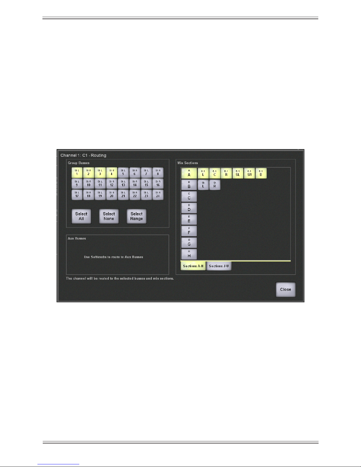
Euphonix Max Air Mixing Console Operation Manual Touchscreen
Select the desired Processes button and then touch one of the Positions buttons to assign that process to the position pointed to by the arrow. The processes move left or right
depending on the position vacated relative to the new position selected. For example, in
Figure 4-38 if EQ is selected and assigned the fourth Positions button, it becomes the
third process with Mtr sliding one position to the left. If Dyn is selected and assigned
the fourth Positions button, it becomes the fourth process with Ins sliding one position
to the right.
Main and Group Bus Routing4.10.2
The Main and Group bus routing for the channel assigned to the Super Channel can be
set by touching the Setup button on the upper-left of the Super Channel View (Figure
4-36).
Touch the Group Busses buttons to assign the channel to those busses (Figure 4-39
shows 1–4 selected). Touch the Main sections to assign the channel to them. Figure 4-39
shows Main section A selected and set to a 5.1-channel format. Use the Select All, Select
None, and Select Range buttons to assist your selection (page 75). Use the Soft Knobs
to route to the Aux Busses.
Channel Routing PopupFigure 4-39
82
Page 83
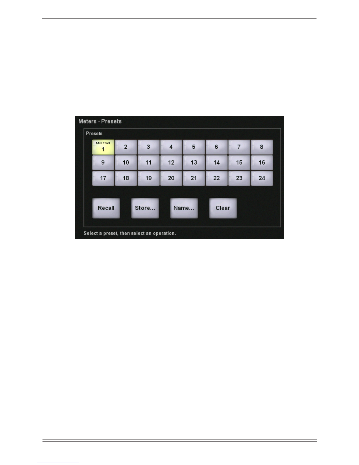
Euphonix Max Air Mixing Console Operation Manual Touchscreen
Meters4.11
Select the Meters Main Menu button to display the Meters View. There are four tabs
along the bottom: Presets, Screen, Fader, and Setup.
Presets4.11.1
After conguring the meters using the Screen, Fader, and Setup tabs discussed below,
the conguration can be captured as a preset, named and recalled for later use.
Meters-Presets PopupFigure 4-40
Select a numbered preset button. Touch the Store button to store the current meter conguration to that preset. Touch the Name button to assign an 8-character name in the
keyboard popup.
To recall a preset, touch the desired preset button and then touch the Recall button.
To delete a preset, touch the desired preset button and then touch the Clear button.
83
Page 84

Euphonix Max Air Mixing Console Operation Manual Touchscreen
Screen4.11.2
Select the Screen tab to congure the meters that will appear across the top and right
side of the Touchscreen. There are eight meter banks, each of which can contain up to
eight channels.
2
5
1
4
3
Meters-Screen Popup with Meters DisplayFigure 4-41
The Function section (1 in Figure 4-41) lists the types of meters that can be displayed.
The Channels function (2) is shown in Figure 4-41, which is representative of the interface for the other functions. The Strips, Channels, Group Masters, and MF Masters
functions have a Show Gain Reduction button (3) which, when activated, displays the
amount of gain reduction applied by the compressor. The Color section (4) lists the six
choices of meter colors available for each meter bank.
Select a meter bank on the top or right of the Touchscreen to assign the meter characteristics to. The meter bank highlights with a yellow rectangle (5).
84
Page 85

Euphonix Max Air Mixing Console Operation Manual Touchscreen
Ext1, Ext2, Ext3, Ext4
Select the Ext1, Ext2, Ext3, or Ext4 tabs to congure the meters that will appear on the
optional External Meters Display.
Meters-Screen=Ext1 Popup with Meters DisplayFigure 4-42
In Figure 4-42, Ext1, which is the top meter bank row of the External Meters Display, is
congured to display channels 49 to 96, and group busses 1 to 8. Figure 4-43 shows an
External Meters Display with Ext1, Ext2, Ext3, and Ext4 fully congured.
85
Page 86

Euphonix Max Air Mixing Console Operation Manual Touchscreen
External Meters Display, fully conguredFigure 4-43
86
Page 87

Euphonix Max Air Mixing Console Operation Manual Touchscreen
Fader4.11.3
Select the Fader tab to display the Meters-Fader View. This congures the meter display
next to the fader (Figure 4-44).
Meters-Fader PopupFigure 4-44
Select a Strip button from the Strips section. Use the Main or Center tabs and the Select
All, Select None, Select Range to assist your selection (page 75). Touch a Meter Dis-
play button to congure the selected Strip.
Fader• : The Main or Swap channel is displayed, depending upon the state of the
strip’s Swap button. When the Swap button is pressed to change from the Main to
Swap channel, the meter follows this change.
Fader with Gain Reduction• : The Main or Swap channel is displayed with gain
reduction.
Main and Swap• : The Main and Swap channels are always displayed in the left
and right meters respectively, regardless of whether the Swap button is pressed or
not.
None• : No meter is displayed.
87
Page 88

Euphonix Max Air Mixing Console Operation Manual Touchscreen
Setup4.11.4
Select the Setup button to display the Meters-Setup View, which determines the meter
ballistics for all currently displayed meters. Select Peak or Average to display the de-
sired meter ballistics.
NOTE: This setting, although not saved with the preset, is saved between system
shutdown and restart.
Events4.12
See Chapter 11: Event System.
Meters-Setup ViewFigure 4-45
88
Page 89

Euphonix Max Air Mixing Console Operation Manual
Channels and StripsChapter 5:
Strips5.1
A CM416 module contains sixteen identical strips. The strip is the physical control area
on the console that contains keys, knobs, displays, and a fader. A Channel performs
all of the signal processing (EQ, dynamics, routing, gain, etc.). Max Air has up to 194
channels, each of which may be assigned to a strip. A strip has room for Swap and Main
channels that can be switched with one key press. Max Air allows tremendous exibility
with how strips are assigned channels and how they are controlled:
Any channel can be assigned to any strip; assignments need not be consecutive.•
Channels with related functions, such as all VTRs, can be assigned to neighboring •
strips.
Two strips can control one channel, allowing convenient access to that channel •
from two locations.
Channel-to-strip assignments can be named, stored, and recalled as • Layouts (see
Layouts on page 157).
Channel settings (EQ, dynamics, routing, gain, etc.) can be named, stored, and •
recalled as Snapshots (see Snapshots on page 159).
Max Air channels are mono unless they are dened as stereo, LCRS, 5.1, 6.1, 7.1 •
formats through Multi Format Masters (see Chapter 8: Control Groups and Multi
Format Masters).
A 96-channel, 48-strip conguration could assign all channels to the control surface:
Main (channels 1–48 to strips 1–48); Swap (channels 49–96 to strips 1–48). A 96-chan-
nel, 32-strip Max Air conguration cannot assign all channels to the console at once but
could use two Layouts to easily interchange the channels. Figure 5-1 shows a strip with
its bus displays that appear on the surface above the channel, and block diagrams for the
Swap and Main channels.
NOTE: The term “active channel” will be used throughout the manual to refer to the
Main or Swap channel currently assigned to the fader.
89
Page 90

Euphonix Max Air Mixing Console Operation Manual Channels and Strips
On
On
On
On
Select
Select
Select
Select
12
72
60
48
42
36
6
0
6
12
18
24
30
clip
0
6
12
24
4848
72
3
6
12
24
Select
Select
Main Channel
Swap Channel
Talk
Select
Chan
48V
ST
Mix-
Lock
MSL
Copy Paste
BusMix-
GroupMain
PanAux
Filt
EQ
Dyn
Ins
Inp
*
Mix
Aux
Group
Knobset
Select
Expand
In Out
1122334455667788
991010 1111 12121313 14141515 1616
17171818 19192020 2121 22222323 2424
1122334455667788
AABBCCDDEEFFGGHH
991010 1111 12121313 1414 15151616
17171818 1919 20202121 22222323 2424
25252626 2727 28282929 30303131 3232
33333434 3535 36363737 38383939 4040
41414242 4343 44444545 46464747 4848
Swap
Solo
On
EQ
Function
4 of 7
Function
5 of 7
Function
6 of 7
Function
7 of 7
Pre-Fader
Output
Solo
PFL/AFL
Aux Sends
Group Busses
Matrix/Clean Feeds
Main Busses
Program/Sub Groups
System Buses
Channel Output
Mix Minus Output
Fader
& Mute
Any
Order
Insert
Function
3 of 7
Function
2 of 7
Delay
DYN
Pan
Pan
Key
Link
Trim & Phase
Input Select
Channel Inputs
AB
Function
2 of 8
Function
1 of 7
Meter
Mix Minus
Processing
Filters
EQ
Function
4 of 7
Function
5 of 7
Function
6 of 7
Function
7 of 7
Pre-Fader
Output
Solo
PFL/AFL
Aux
Sends
Group Busses
Matrix/Clean Feeds
Main Busses
Program/Sub Groups
System Buses
Channel Output
Mix Minus Output
Fader
& Mute
Any
Order
Insert
Function
3 of 7
Function
2 of 7
Delay
DYN
Pan
Pan
Key
Link
Trim & Phase
Input Select
Channel Inputs
AB
Function
2 of 8
Function
1 of 7
Meter
Mix Minus
Processing
Filters
Console Strip and Bus display with block diagrams for Main and Swap channelsFigure 5-1
90
Page 91
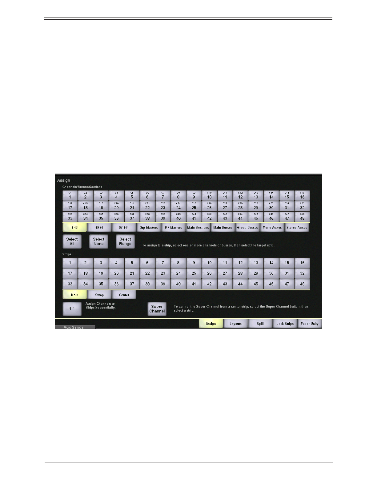
Euphonix Max Air Mixing Console Operation Manual Channels and Strips
Assign Channels to Strips5.1.1
Each strip can control a Main and Swap channel. One or both of the channels can be a
Control Group Master or Multi Format Master instead of a normal channel (see Chapter
8: Control Groups and Multi Format Masters). Channels can be assigned individually
using the strip controls or to multiple strips using the Surface - Assign View (see Chan-
nels on page 74) from the Touchscreen.
Surface Assign View
The Surface - Assign View on the Touchscreen is most commonly used to assign chan-
nels to multiple strips but can also be used for a single assignment.
Select 1. Channels from the Main Menu buttons.
Select the 2. Assign tab.
In the 3. Surface Assign View, select the channel to assign from the Channels bank.
Select the strip to assign the selected channel to from the 4. Strips bank.
Surface Assign ViewFigure 5-2
91
Page 92

Euphonix Max Air Mixing Console Operation Manual Channels and Strips
Assign Multiple Channels
Use the following procedure to assign multiple, consecutive channels to the console
surface:
In the 1. Surface Assign View, select Select Range.
Select the rst and last channel of a range of channels from the Channels bank.2.
Select the rst strip from the 3. Strips bank.
The selected range of channels is assigned to strips starting at the rst selected
strip.
Assign Channels Sequentially
Select 1:1 to automatically assign channels, starting with channel 1, to the main layer of
all strips starting at strip 1.
Super Channel
To assign a strip to follow the Super Channel:
Select 1. Super Channel (below the channels bank).
Select a strip from the strips bank2.
Any channel assigned to the Super Channel is now controlled by that strip.
Using the Strip to Assign Individual Channels
The Chan Select key can be used to assign individual channels to the console surface:
Press the 1. Swap key to assign the Main or Swap channel.
Press and hold down the 2. Wave key and press the Chan Select key.
The Channel Selector appears on the Touchscreen.
92
Page 93
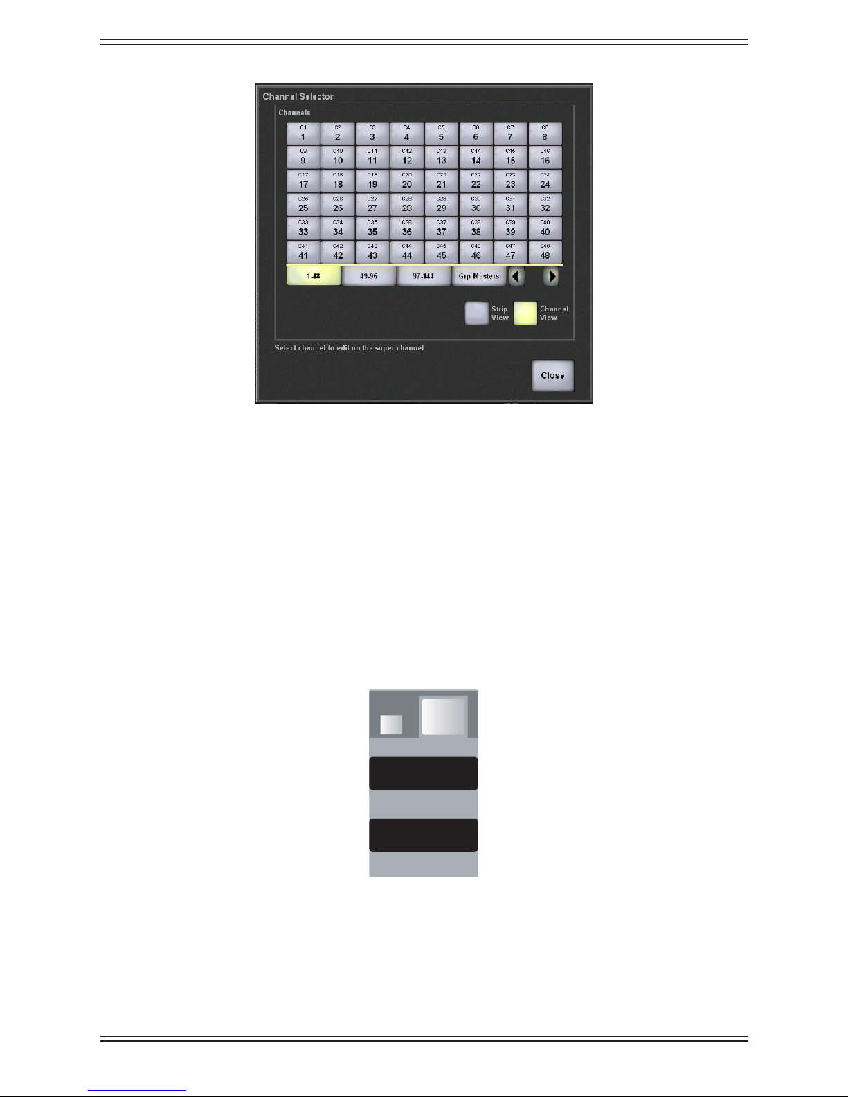
Euphonix Max Air Mixing Console Operation Manual Channels and Strips
MainChannel
Swap Channel
Main Channeln
Swap
Channel SelectorFigure 5-3
Select the channel (1–48, 49–96, 97–144), 3. Grp Master (Control Group Master),
or MF Master (Multi Format Master) to assign to the strip.
Channel Control Features5.2
Channel Name5.2.1
The Main and Swap channels are designated by a number (C# by default) or by an eightcharacter name assigned in the Patch View (see Patch on page 54). The Main channel is
below the Swap channel. Press the Swap key to key between the Swap and Main channels. The strip functions control only the active channel.
Main and Swap Channel displaysFigure 5-4
93
Page 94

Euphonix Max Air Mixing Console Operation Manual Channels and Strips
12
60
5
0
5
10
20
30
40
clip
0
6
12
24
4848
72
3
6
12
24
Select
Select
Select
Chan
48V
ST
Mix-
Lock
MSL
Solo
On
Fader5.2.2
Chan Select key
Channel On
Select key
Fader select
key
Wave Key
Status LEDs
Meters
Solo key
Channel On key
Status LEDs
Touch Sensitive fader
Gain reduction LEDs
Strip FaderFigure 5-5
Each strip has a touch-sensitive moving fader. The fader has 12 dB headroom from the
0 dB position.
Fader Select Key
The fader Select key is used to select the fader for copy (page 96) and clear operations
(page 150).
94
Page 95

Euphonix Max Air Mixing Console Operation Manual Channels and Strips
Backstop PFL
The Max Air faders have a backstop key past the bottom of their travel. Pull a fader back
to route the channel’s PFL signal to the solo bus. Releasing the fader cancels that fader’s
routing to the solo bus. Backstop PFL can be used on group masters to solo a control
group. See page 145 for more information.
Meters5.2.3
The meter can show the active channel, or Main and Swap, and can also show gain
reduction in the bottom four LEDs on the right meter (see Meters on page 83). Stereo
channels display the left and right channels on the left and right sides of the meter, respectively.
Status LEDs5.2.4
The following explanations pertain to the LED being illuminated.
48 V• : phantom power is on for the mic preamp of the active channel.
Phase• : phase is inverted for the active channel.
Lock• : strip is locked (page 77).
ST• : active channel is stereo (page 154).
Mix Minus• : mix minus key is pressed (page 110).
Fader Touch Sensor LED• : fader is being touched.
M• : active channel is Group or Multi Format Master (Chapter 8: Control Groups
and Multi Format Masters).
S• : active channel is a slave to a Group or Multi Format Master (Chapter 8: Control
Groups and Multi Format Masters).
L• : reserved for future use
Wave Key5.2.5
Pressing the Wave key has two functions:
brings the channel to the center Super Channel (see page 128).•
modies other keys like a shift key.•
Channel On Key5.2.6
The On key turns the channel on and off.
95
Page 96

Euphonix Max Air Mixing Console Operation Manual Channels and Strips
Channel On Select Key
The Select key is used to include the channel On key in copy and clear operations.
Channel Select Key5.2.7
The Chan Select key is used:
to include the entire channel in a copy or clear operation.•
in conjunction with the • Wave key to assign channels (page 92).
Solo Key5.2.8
The Solo key is used to solo the active channel (page 142).
Copy and Paste5.2.9
Settings from one channel may be copied and pasted to others.
To copy the settings:
Press and hold the 1. Wave key down and press the Copy key.
The strip dims and the Copy key ashes.
Press the 2. Chan Select key to select the entire channel, or press any Knobset Select
key at the top of the strip to copy that function to the copy buffer. Other functions
can be added to the buffer by pressing their Knobset Select keys.
Press and hold the 3. Wave key down and press the Copy key to stop it from ashing
and exit the mode.
To paste the settings to a new channel:
Select the Swap or Main channel within the desired strip.1.
Press and hold the 2. Wave key down and press the Paste key on the new channel.
The buffered information is pasted to the channel on the new strip.
Rotary Knobs5.2.10
Each strip has four rotary knobs each with a four-character display and two keys. The
knob is a continuous controller; as the knob turns, the LEDs on the outer ring light. The
display shows the knob’s current function or parameter value.
The lower key to the left of the knob toggles the knob’s function • In/Out.
The upper key to the left of the knob is the • Select key for the In/Out key below
it. This key is also used to select the On/Off key for inclusion in a Snapshot and
96
Page 97

Euphonix Max Air Mixing Console Operation Manual Channels and Strips
On
Select
BusMix-
GroupMain
PanAux
Filt
EQ
Dyn
Ins
Inp
*
Knobset
Select
Expand
In Out
pages to a second knobset function, if it exists.
Rotary Knob ControlsFigure 5-6
Knobset Select Keys5.2.11
The Input, Dynamics, EQ, Filters, Pan, Aux, and Routing functions can be assigned
to a strip’s four rotary knobs by the Knobset Select keys above the knobs. If the function
has more than four parameters, the ◄► keys (below the rst knob) page backward and
forward to display the additional settings. The Ins/Inp, Dyn, EQ and Filt keys double
as process in/out keys when the In/Out key is selected.
Strip Function SwitchesFigure 5-7
97
Page 98
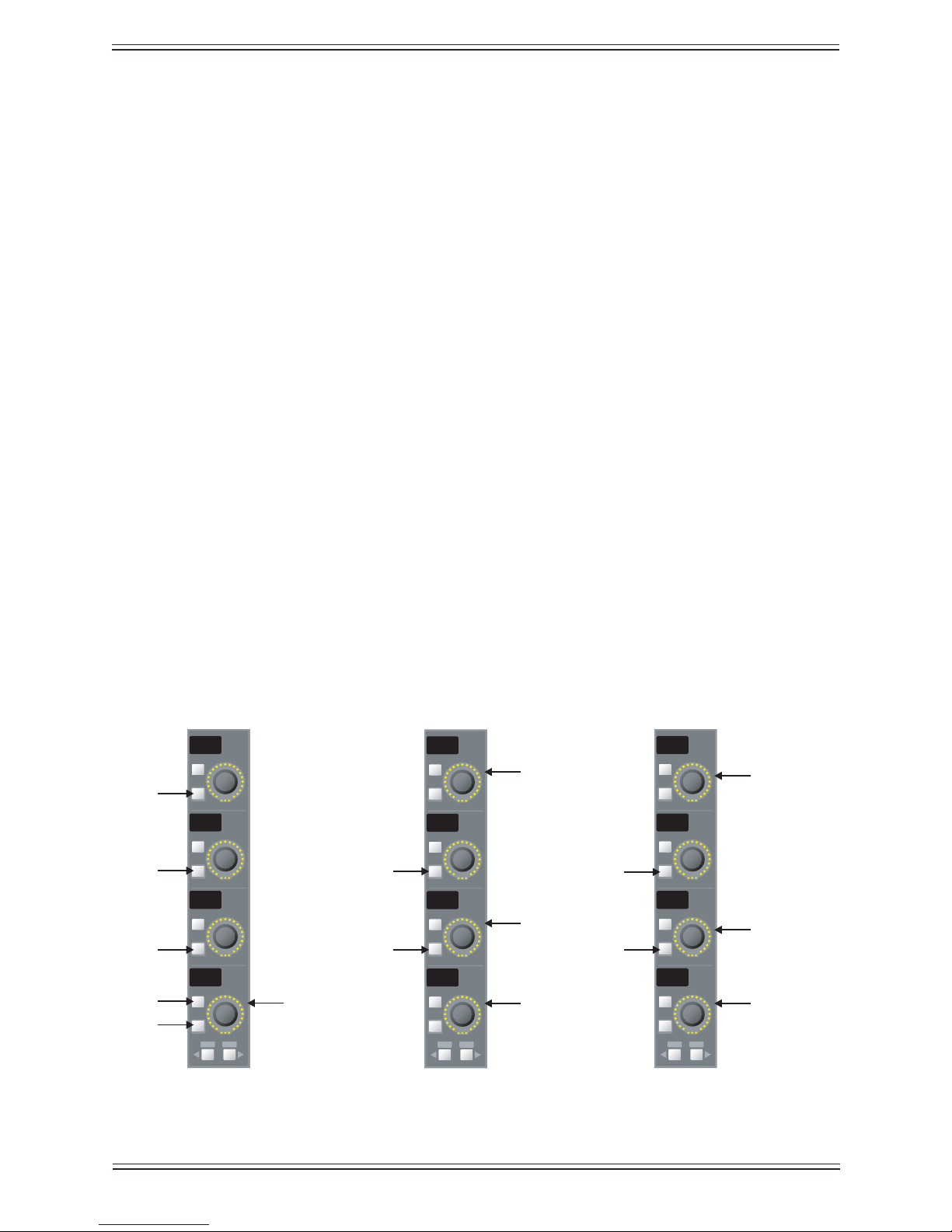
Euphonix Max Air Mixing Console Operation Manual Channels and Strips
On
On
On
On
Select
Select
Select
Select
Copy Paste
HiZ
48v
HPF
Gain
On
On
On
On
Select
Select
Select
Select
Copy Paste
Atrm
Aphs
Dly
Inpt
On
On
On
On
Select
Select
Select
Select
Copy Paste
Btrm
Bphs
Dly
Inpt
Page 1Page 2 Page 3
Input Select
Delay
Mic Gain
B Input Trim
Delay
Input Select
B Input
A Input
On/Off
On/Off
On/Off
On/Off
On/Off On/Off
On/Off
A Input Trim
In/Out Keys5.2.12
There is one In/Out key for each set of eight strips. When this key is on, the Ins/Inp,
Dyn, EQ and Filt keys act as function in/out keys. When the In/Out key is off, the Ins/
Inp, Dyn, EQ, and Filt keys return to their knobset selection mode but remain half-lit if
the function has been switched in.
Expand5.2.13
There is one Expand key for each set of eight strips. Expand has not been implemented
in v3.0 software.
Channel Processing Functions5.3
Max Air provides exible and complete processing functions for each channel: Input,
Dynamics, EQ, Filters, Panning, Aux Busses and Routing.
Inputs5.3.1
Press the Ins/Inp Knobset Select key to display the input controls on the knobs. Press
the ► key to display the B input page with the same controls as the A input.
Each channel has an A and B input. The Inpt knob (bottom) can feed A, B, or A+B to the
channel. These two inputs can be used in many ways but a common application is one
Mic and one Line. Another common use is for backup mic inputs: Channel 1A is from
the main mic while 1B is from the backup. The Inpt knob then acts as a main/backup
mic key.
Mono Input knobsetsFigure 5-8
98
Page 99

Euphonix Max Air Mixing Console Operation Manual Channels and Strips
Analog Controls
If an ML530 Mic/Line Interface or Modular I/O Remote Preamp is patched to the input,
the knobs show the analog mic/line controls:
HiZ• : Press the lower key to the left of the knob to toggle the input between high
and low impedance. When the key is lit, the input is high impedance.
48V• : Press the lower key to the left of the knob to toggle phantom power on/off.
When the key is lit, phantom power is on.
HPF• : Press the lower key to the left of the knob to toggle the high-pass lter on/
off. When the key is lit, the high-pass lter is on.
Gain• : Rotate the knob to adjust the analog input gain between -12 and +72 dB.
The upper key toggles the A input on/off, and the lower key toggles the B input on/
off. Press both keys down to mix the A and B inputs together.
NOTE: There is a +12dB offset between the Gain knob dB reading and the Modular
I/O Remote Preamp’s actual gain position. When the Gain knob displays
-12dB, the Modular I/O Remote Preamp’s setting is 0dB.
If an ML530 Mic/Line Interface or Modular I/O Remote Preamp is not patched to the
input, the rst page does not appear.
Digital Controls
The second page controls the digital parameters of the A and B inputs:
Atrm:• This knob adjusts the digital trim ±15 dB.
Aphs:• Press the lower key to the left of the knob to toggle the phase. The key lights
to indicate phase reversal. There is also a phase reversal light next to the fader.
Dly:• Press the lower key to the left of the knob to enable the delay. The key lights
to indicate the delay is active. Pressing the upper key to the left of the knob displays the delay knobset. The top knob adjusts the delay in one second increments.
The second knob down adjusts the delay in single frame increments. The third
knob down adjusts the delay in sub-frame increments. The bottom knob adjusts the
delay in single sample increments. The maximum amount of delay is 2 seconds.
Inpt:• This knob selects between inputs A, B, and A+B (mixes both inputs).
Atrm and Aphs have corresponding controls for the B input; Dly and Inpt adjust one
parameter that applies to both inputs.
99
Page 100
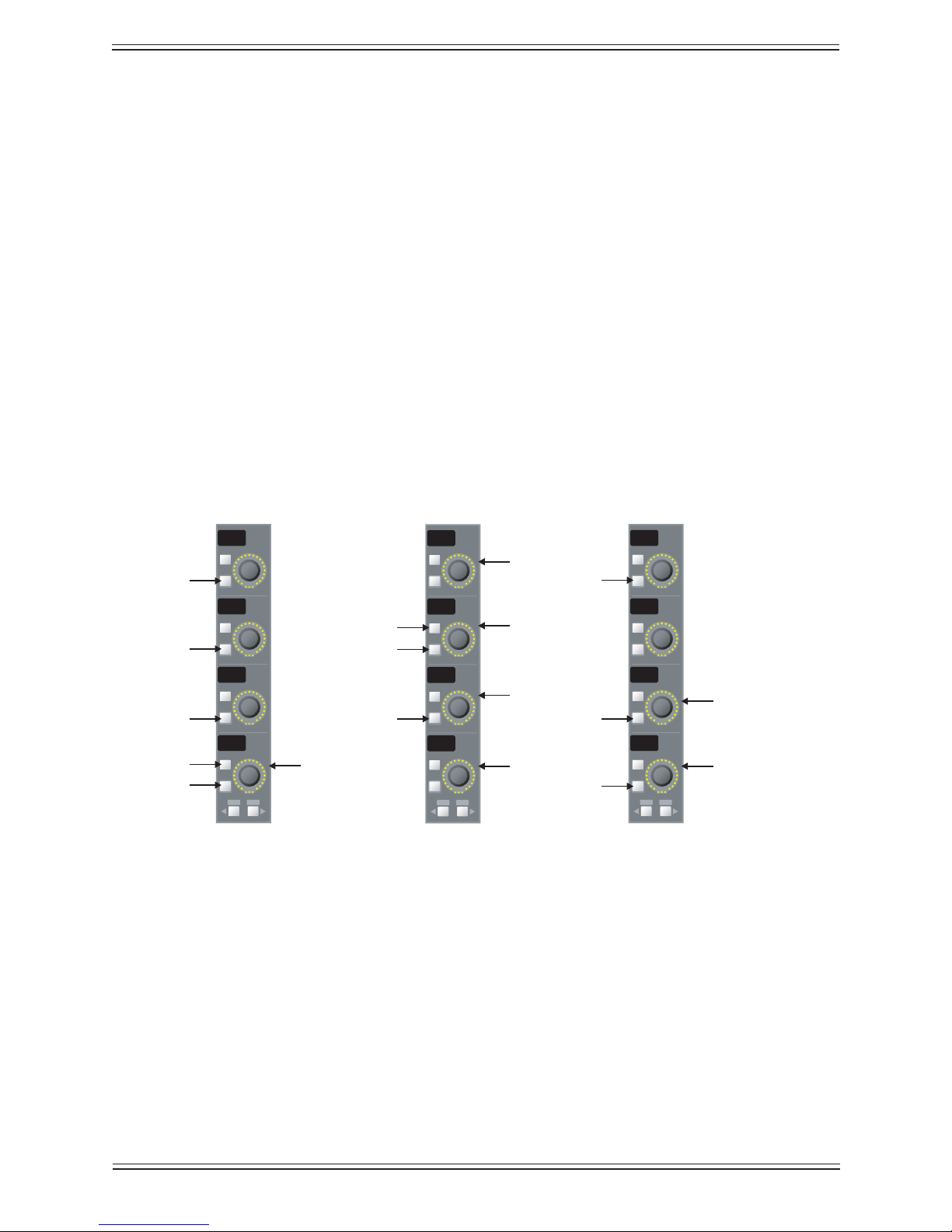
Euphonix Max Air Mixing Console Operation Manual Channels and Strips
On
On
On
On
Select
Select
Select
Select
Copy Paste
HiZ
48v
HPF
Gain
On
On
On
On
Select
Select
Select
Select
Copy Paste
Trim
Bal
Dly
Inpt
On
On
On
On
Select
Select
Select
Select
Copy Paste
Swap
Aphs
Bphs
Page 1Page 2 Page 3
Input Select
Delay
Mic Gain
A Input Phase
B Input Phase
B Input
A Input
On/Off
On/Off
On/Off
Right to Mono
Left to Mono
On/Off On/Off
On/Off
On/Off
Input Trim
Balance
Stereo Controls
There are two additional controls used for stereo channels (see Multi Format Master
Channels on page 154).
Balance• : Rotate the Bal knob left to hear more of the left channel; rotate right to
hear more of their right channel. Rotate left or right until the display reads 100L or
100R to hear only the left or right channel.
Left-to-mono• : Press the upper key next to the Bal knob to send the left channel
equally to both the left and right sides of the stereo channel.
Right-to-mono:• Press the lower key next to the Bal knob to send the right channel
equally to both the left and right sides of the stereo channel.
Both-to-mono:• Press both keys next to the Bal knob to send a mono mix of both
channels equally to both sides of the stereo channel. The Bal knob then adjusts the
mix between left and right channels.
Swap:• Press the lower key to reverse the left and right channels.
Stereo Input KnobsetsFigure 5-9
100
 Loading...