

Page 1
CS3000
CS2000
Operation Manual
Version 3.0
Revision 1
Page 2

Table of Contents
CS3000/2000
Operation Manual
Version 3.0
Revision 1
Worldwide Sales, Euphonix Inc. 11112 Ventura Blvd. #301, Studio City, CA 91604
Voice: (818) 766-1666 / Fax: (818) 766-3401
Corporate HQ, Euphonix Inc. 220 Portage Ave, Palo Alto, CA 94306-2242
Voice: (650) 855-0400 / Fax: (650) 855-0410 / Web Page: www.euphonix.com
Publish Date: October 1997
Operation Manual Part Number: 840-05134-01
In the interest of continued product development, Euphonix reserves the right to make improvements
in this manual and the product it describes at any time, without notice or obligation.
CS3000, CS2000, MixView, Crescendo, Total Automation, SnapShot Recall, Audio CUBE, Digital Studio Controller,
©1996 Euphonix Inc. All rights reserved worldwide. No part of this publication may be reproduced, transmitted,
transcribed, stored in a retrieval system, or translated into any language in any form
ii Euphonix CS3000/2000 Operation Manual
DSC, GainBall and GainCurve are trademarks of Euphonix Inc.
by any means without written permission of Euphonix Inc.
Page 3

Table of Contents
TABLE OF CONTENTS
SECTION 1 : INTRODUCTION................................ 1 - 1
System Component:............................................................................. 1 - 3
The Mix Controller...................................................................................................1 - 3
The Audio Tower......................................................................................................1 - 4
The Support Computer ............................................................................................1 - 5
The Patchbay ...........................................................................................................1 - 5
I/O Channel Module ................................................................................................1 - 6
Master Module........................................................................................................1 - 7
The DSC...................................................................................................................1 - 8
This Manual.............................................................................................................1 - 9
Useful Symbols........................................................................................................1 - 9
The DSC (Digital Studio Control) Module ......................................1 - 11
Master Control Panel ............................................................................................1 - 12
Dedicated Keys......................................................................................................1 - 13
Using the Dedicated Keys .....................................................................................1 - 14
Assignable Rotary Control Set ..............................................................................1 - 15
Mode Select Keys .................................................................................................1 - 16
Equalizers ..............................................................................................................1 - 17
Dynamics ...............................................................................................................1 - 18
Assignable Keys ....................................................................................................1 - 19
Channel/Route Select Keys...................................................................................1 - 20
Track Assign Keys..................................................................................................1 - 21
Transport Controls ................................................................................................. 1 - 21
Monitor Section.....................................................................................................1 - 21
Assignable Moving Faders....................................................................................1 - 22
CS3000D I/O Block Diagram (Rev F) ............................................... 1 - 23
CS3000P/B I/O Block Diagram (Rev F)............................................1 - 24
CS2000 I/O Audio Block Diagram (Rev E) ...................................... 1 - 25
CS3000 Master Audio Block Diagram (Stereo Outputs).............. 1 - 26
CS3000 Master Audio Block Diagram (Aux & Monitor Outputs) 1 - 27
Euphonix CS3000/2000 Operation Manual iii
SECTION 2 : GETTING STARTED ............................ 2 - 1
The Screen Display ............................................................................. 2 - 3
Startup Screen.........................................................................................................2 - 3
Status Bar................................................................................................................2 - 4
The SmartDisplay and Master Control Panel ................................. 2 - 5
Save Your Work ................................................................................... 2 - 5
MAKE A BACKUP!!!................................................................................................2 - 5
File Hierarchy ....................................................................................... 2 - 6
A typical MixView file tree: ....................................................................................2 - 6
Mounting Disks .................................................................................... 2 - 6
System Data Organization..................................................................2 - 7
List Selection........................................................................................ 2 - 8
Disk Selection....................................................................................... 2 - 8
Page 4

Table of Contents
Projects ................................................................................................. 2 - 9
New Project.............................................................................................................2 - 9
Project Comments ...................................................................................................2 - 9
Rename Project .....................................................................................................2 - 10
Delete Project........................................................................................................2 - 10
Copy Project...........................................................................................................2 - 10
Titles..................................................................................................... 2 - 11
Title Hierarchy .......................................................................................................2 - 12
New Title...............................................................................................................2 - 12
Title Comments......................................................................................................2 - 13
What’s in a Title?...................................................................................................2 - 13
Save Title...............................................................................................................2 - 13
Load Title...............................................................................................................2 - 13
Title Utilities Menu................................................................................................2 - 14
Title Rename, Delete and Copy.............................................................................2 - 14
Backing Up Title onto a Removable Cartridge ......................................................2 - 15
Title Setup Menu...................................................................................................2 - 15
Mixes ................................................................................................... 2 - 16
SECTION 3 : SNAPSHOT RECALL........................... 3 - 1
The Master Control Panel .................................................................. 3 - 3
Interactive Screen Display ................................................................ 3 - 4
Recalling (RCL) a Snapshot................................................................3 - 4
Assignable keys (seen in snapshot mode) ..............................................................3 - 4
Snapshot Mode .......................................................................................................3 - 5
SpinKnob .................................................................................................................3 - 5
Numeric keypad, [+]/[–] keys...................................................................................3 - 5
Storing (STO) a Snapshot................................................................... 3 - 6
Using the Master Control Panel..............................................................................3 - 6
IMPORTANT! .................................................................................................................. 3 - 6
IMPORTANT! .................................................................................................................. 3 - 7
Rename a Snapshot ................................................................................................3 - 7
Single Channel SnapShot Recall ...................................................... 3 - 7
Nulling Controls.................................................................................... 3 - 8
Standard Faders ......................................................................................................3 - 8
Motorized Faders.....................................................................................................3 - 8
Auto Null Selected (a) .............................................................................................3 - 9
Manual Null Selected (m) .......................................................................................3 - 9
Zeroing the Desk................................................................................3 - 10
CLEAR All Snapshot Memories .......................................................3 - 10
Match Current Position .................................................................... 3 - 10
Auto-Backup....................................................................................... 3 - 11
Recalling the Backup Snapshot...................................................... 3 - 12
Isolate During SnapShot Recall ......................................................3 - 12
Items NOT Stored as part of SnapShot Recall ............................. 3 - 12
SECTION 4 : TUTORIAL ...................................... 4 - 1
iv Euphonix CS3000/2000 Operation Manual
Signal Flow Diagram Symbols........................................................... 4 - 3
Channel Blocks .................................................................................... 4 - 4
Page 5

Table of Contents
Routing Parameters............................................................................. 4 - 4
Source......................................................................................................................4 - 4
Assign......................................................................................................................4 - 4
Mode .......................................................................................................................4 - 4
Exercise 1 Stereo Source/Stereo Fader/Stereo Bus/Monitor ..... 4 - 5
Source......................................................................................................................4 - 5
Assign......................................................................................................................4 - 5
Mode .......................................................................................................................4 - 6
Meters ................................................................................................... 4 - 6
Channel (I/O) Meter Selection ................................................................................4 - 7
Metering Presets.....................................................................................................4 - 8
Master Module Meter Selection ............................................................................4 - 8
Stereo Output Faders ..............................................................................................4 - 9
Save That Console...................................................................................................4 - 9
Monitor Source Selection .......................................................................................4 - 9
Universal Input Amplifiers (UIAs) M1 & M2.................................. 4 - 10
Bus/Tape switching ...............................................................................................4 - 10
Equalizers............................................................................................4 - 11
Phase Reverse, Filter, Phantom Power..................................................................4 - 11
Stereo Linking EQs ................................................................................................4 - 12
Adjusting EQ with the DSC ...................................................................................4 - 13
Default EQ Values..................................................................................................4 - 13
EQ Screen Display .................................................................................................4 - 14
Frequency Range ...................................................................................................4 - 14
EQ Routing Source.................................................................................................4 - 14
EQ Curves ..............................................................................................................4 - 15
Q Range .................................................................................................................4 - 16
Musical Note Value Display..................................................................................4 - 16
Adjusting the EQ Using Keypad ............................................................................4 - 17
Copying EQ values.................................................................................................4 - 17
Cascading 2 EQs to Produce an 8-Band EQ...........................................................4 - 18
Insert Points........................................................................................ 4 - 18
Exercise 2 Stereo Inserts into Audio Path..................................... 4 - 19
Insert Diagrams, Pre- & Post-EQ ....................................................4 - 20
Exercise 3 Multitrack Monitoring ................................................... 4 - 21
Clear Channel ........................................................................................................4 - 21
Clear Block.............................................................................................................4 - 21
Copy Channel.........................................................................................................4 - 21
Copy Block .............................................................................................................4 - 21
Clear/Copy Objects................................................................................................4 - 21
Recalling the Default Snapshot (Zeroing the Console).........................................4 - 22
Construct Signal Path............................................................................................4 - 23
Block Copy .............................................................................................................4 - 23
Copy One Setting...................................................................................................4 - 23
Add EQ...................................................................................................................4 - 24
I/O Metering for Multitracking..............................................................................4 - 24
Mono Insert Point..................................................................................................4 - 24
Sound! ...................................................................................................................4 - 24
Exercise 4 Multitrack Routing ......................................................... 4 - 25
Source....................................................................................................................4 - 25
Assign....................................................................................................................4 - 25
Mode .....................................................................................................................4 - 25
Bus Summing Amps ..............................................................................................4 - 26
Euphonix CS3000/2000 Operation Manual v
Page 6

Table of Contents
MT Bus to Out3................................................................................... 4 - 26
L4 Bus/Tape Switching..................................................................... 4 - 27
Querying a Channel’s Bus/Line Routing ........................................ 4 - 27
Adding EQ To M1...................................................................................................4 - 27
Saving to a Snapshot ............................................................................................4 - 27
Stereo Inputs to Multitrack ...................................................................................4 - 28
Auxiliary Sends .................................................................................. 4 - 29
Overview ............................................................................................. 4 - 29
Aux Modes..........................................................................................4 - 29
Exercise 5............................................................................................4 - 29
Mono Independent Mode......................................................................................4 - 29
Fader Source Tracking .....................................................................4 - 31
Exercise 6............................................................................................4 - 31
Configuring Aux Send Modes..........................................................4 - 32
Mono Ind Modes (mono in/mono out) ..................................................................4 - 32
Level/Pan Linked Modes (mono in/stereo out) (stereo in/stereo out)..................4 - 32
Mono Independent ”0dB” Locked Mode...............................................................4 - 32
Exercise 7............................................................................................4 - 33
Mono Pan Mode....................................................................................................4 - 33
Mono Pan Center Locked Mode............................................................................4 - 34
Mono mode ...........................................................................................................4 - 34
Exercise 8............................................................................................4 - 35
Stereo Balance mode ............................................................................................4 - 35
Stereo Center Locked mode ..................................................................................4 - 36
Stereo Individual mode .........................................................................................4 - 36
Stereo Reverse Modes..........................................................................................4 - 36
Copying an Aux Setup.......................................................................4 - 36
SOLO AFL and PFL ............................................................................. 4 - 37
AFL Mode ..............................................................................................................4 - 37
KILL SOLO Mode (Solo In Place)............................................................................4 - 38
Kill Solo Safe.........................................................................................................4 - 38
Intercancelling Solo Mode ....................................................................................4 - 38
PFL Mode...............................................................................................................4 - 38
Direct Outputs .................................................................................... 4 - 39
Default DIR Assignment........................................................................................4 - 39
Changing the Default ............................................................................................4 - 39
The Combiner ..................................................................................... 4 - 41
Combiner/DIR Experiments ...................................................................................4 - 42
Master Module Signal Flow Options.............................................. 4 - 46
Main Stereo Outputs.............................................................................................4 - 46
Stereo Bus Insert Points........................................................................................4 - 46
Switching the Stereo Insert Point .........................................................................4 - 47
Stereo Output Level...............................................................................................4 - 47
Stereo Output Balance ..........................................................................................4 - 47
0.00dB....................................................................................................................4 - 47
External Monitor Inputs.........................................................................................4 - 48
Talkback .................................................................................................................4 - 50
Oscillator ...............................................................................................................4 - 50
CLIP Indicator Options ...........................................................................................4 - 52
D Monitor/Phones .................................................................................................4 - 53
Monitor SET Options .........................................................................4 - 54
Monitor AutoMute ................................................................................................4 - 54
Monitor Link ..........................................................................................................4 - 54
vi Euphonix CS3000/2000 Operation Manual
Page 7

Table of Contents
Monitor Dim ..........................................................................................................4 - 54
Monitor Combinations and Examples ...................................................................4 - 55
Film Monitor Mode................................................................................................4 - 55
Film 4-Track Dolby Monitoring Diagram ...............................................................4 - 56
Film 5.1 Monitoring Diagram ................................................................................4 - 57
M/S (Sum & Difference) Modes......................................................4 - 58
Stereo Width Effect Using M & S Signal Encoding..............................................4 - 58
M/S Decoder .........................................................................................................4 - 58
M/S Channel Operation Block Diagram................................................................4 - 59
MIDI Machine Control ......................................................................4 - 60
Tape Transport and Locate..............................................................4 - 60
Locate Menu System ........................................................................4 - 62
Cue List and Menu.............................................................................4 - 63
Cue Points........................................................................................... 4 - 64
Virtual Timecode and the “VTM” ..........................................................................4 - 64
Locating to a Manual Entry ...................................................................................4 - 64
Locating using Shuttle Mode (SpinKnob)..............................................................4 - 64
Storing and Locating to Cues ................................................................................4 - 64
Locating to the Head/Tail ......................................................................................4 - 65
Locating to the Mark Point....................................................................................4 - 65
Locating from the Cue List ....................................................................................4 - 65
Capture Cues “On The Fly”....................................................................................4 - 66
Recall A Cue (Locating) .........................................................................................4 - 66
Next Cue/Last Cue ................................................................................................4 - 67
Editing the Cue List ...............................................................................................4 - 67
Assigning Custom Cue Names..............................................................................4 - 68
Duplicating Individual Cues...................................................................................4 - 68
Deleting Cues from the Cue List ...........................................................................4 - 68
Deleting the Entire Cue List ..................................................................................4 - 68
Saving the Cue List................................................................................................4 - 68
RollBack and PreRoll ........................................................................ 4 - 69
Cycling................................................................................................. 4 - 69
Locating To Start (LTS) Function..................................................... 4 - 70
Fader Names ...................................................................................... 4 - 70
Euphonix CS3000/2000 Operation Manual vii
SECTION 5 : THE PATCHBAY ................................ 5 - 1
Half-Normalling....................................................................................5 - 4
The Euphonix Patchbay System........................................................5 - 5
Patchbay Layout .................................................................................. 5 - 6
Channel Patch Unit..................................................................................................5 - 7
User Connections ....................................................................................................5 - 7
Channel Inputs and Outputs .............................................................. 5 - 8
Inputs.......................................................................................................................5 - 8
Outputs ....................................................................................................................5 - 8
Insert Points.............................................................................................................5 - 8
Normalling the Multitrack Returns .........................................................................5 - 9
Normalling the Multitrack Sends............................................................................5 - 9
Normalling the Dynamics........................................................................................5 - 9
Normalling the Audio CUBE ..................................................................................5 - 10
Master Patch Unit.............................................................................. 5 - 11
User Connections ..................................................................................................5 - 11
Page 8

Table of Contents
Master Inputs and Outputs ..............................................................5 - 12
External Inputs Ext 1 In (A, B & C), Ext 2 In (A, B & C) ..........................................5 - 12
Auxiliary Bus Outputs (A1-A8)...............................................................................5 - 12
Stereo Bus Outputs ST1 Out (A, B & C), ST2 Out (A, B & C).................................5 - 12
Monitor Outputs (Mon A Out, Mon B Out, Mon C Out) ........................................5 - 12
Monitor Outputs Continued… ..............................................................................5 - 13
Talkback In/Out (TB Out, TB In) .............................................................................5 - 13
Mults .....................................................................................................................5 - 13
Tie-Line Patch Unit............................................................................ 5 - 14
System Supplied Without Euphonix Patchbays ........................... 5 - 14
SECTION 6 : MOVING FADERS.............................. 6 - 1
Moving Faders (DSC) .......................................................................... 6 - 3
Moving Faders (Channel) ................................................................... 6 - 3
Moving Faders vs Standard Faders:........................................................................6 - 3
SmartDisplay Menus...........................................................................6 - 4
Moving Fader Options.........................................................................6 - 4
Motors ON/OFF .......................................................................................................6 - 5
Touch ON/OFF..........................................................................................................6 - 5
Release ON/OFF ......................................................................................................6 - 6
Slaves follow On/Off...............................................................................................6 - 6
First Punch Manual ............................................................................. 6 - 7
SECTION 7 : AUTOMATION .................................. 7 - 1
Overview ............................................................................................... 7 - 3
Setup......................................................................................................7 - 3
Timecode Reference................................................................................................7 - 3
Reference Source Select.........................................................................................7 - 4
New Mix................................................................................................ 7 - 4
The Mix Snapshot ...................................................................................................7 - 5
Creating a New Mix ................................................................................................7 - 5
Naming a New Mix .................................................................................................7 - 5
New Mix Dialog..............................................................................................................7 - 5
Mix Comments ........................................................................................................7 - 6
Mix Screen .....................................................................................................................7 - 6
Mix Menu ................................................................................................................7 - 6
Introduction to the Automation Template ...............................................................7 - 7
DSC Dedicated Automation Keys ..................................................... 7 - 8
Switching Automation On................................................................... 7 - 9
The Punch key..........................................................................................................7 - 9
Object Select keys...................................................................................................7 - 9
Recording Moves............................................................................... 7 - 10
Fader Moves..........................................................................................................7 - 10
Null Lights .............................................................................................................7 - 10
Punch Out ..............................................................................................................7 - 10
Initial Pass....................................................................................................................7 - 10
Pan Move...............................................................................................................7 - 10
Mute Move............................................................................................................7 - 10
Pass Control........................................................................................ 7 - 11
Screen Anatomy ....................................................................................................7 - 11
Pass Tree................................................................................................................7 - 11
Event Count ...........................................................................................................7 - 11
viii Euphonix CS3000/2000 Operation Manual
Page 9

Table of Contents
EDIT .......................................................................................................................7 - 11
CUES......................................................................................................................7 - 11
SNAPS ...................................................................................................................7 - 11
AUX A-D ................................................................................................................7 - 11
PAN BAL ................................................................................................................7 - 11
UF and LF (Faders) .................................................................................................7 - 12
ON (Mute)..............................................................................................................7 - 12
Pass Control SmartDisplay Menus................................................. 7 - 12
Saving a Mix/Undo/Redo......................................................................................7 - 12
Clearing Passes .....................................................................................................7 - 12
Packing Passes ......................................................................................................7 - 12
View menu....................................................................................................................7 - 13
View Scale....................................................................................................................7 - 13
Full/Half Screen............................................................................................................7 - 13
Show Automation Viewer..............................................................................................7 - 13
Zoom Factor .................................................................................................................7 - 14
Trim Mode...........................................................................................7 - 14
WIn, WOut & WThr Modes.............................................................. 7 - 15
ABS WIn Mode......................................................................................................7 - 16
ABS WOut Mode...................................................................................................7 - 16
ABS WThr Mode ...................................................................................................7 - 17
Trim WIn, WOut, WThr..........................................................................................7 - 17
Punch Menu .......................................................................................7 - 17
Monitor Before Record (MBR) ........................................................7 - 19
Exercise 1............................................................................................7 - 19
Engaging MBR mode.............................................................................................7 - 20
Aborting MBR Mode .............................................................................................7 - 20
Punching-In ................................................................................................................. 7 - 20
More on Templates ...........................................................................7 - 20
Set Mode...............................................................................................................7 - 21
Dyn Mode ..............................................................................................................7 - 21
Isolate Mode .........................................................................................................7 - 21
Safe Modes ...........................................................................................................7 - 21
Set Safe ........................................................................................................................7 - 21
Iso Safe ........................................................................................................................ 7 - 22
Dyn Safe.......................................................................................................................7 - 22
SnapShot Suppression ..........................................................................................7 - 22
Suppression Menu ................................................................................................7 - 22
Suppression Screen...............................................................................................7 - 23
Automated EQ..................................................................................... 7 - 23
EQ Object key ........................................................................................................7 - 23
Writing EQ Moves .................................................................................................7 - 23
All Parameter Punch..............................................................................................7 - 23
Individual Parameter Punch...................................................................................7 - 23
Playing EQ Moves..................................................................................................7 - 23
Monitor Before Record (MBR)...............................................................................7 - 24
Automation Editing ............................................................................7 - 24
Edit Operations......................................................................................................7 - 24
Edit Template......................................................................................7 - 26
Edit Descriptions ...................................................................................................7 - 26
Edit Region.......................................................................................... 7 - 26
Manual Timecode entry.........................................................................................7 - 26
Using Cue/Locate points .......................................................................................7 - 27
On-The-Fly .............................................................................................................7 - 27
Offline Trim ............................................................................................................7 - 27
Euphonix CS3000/2000 Operation Manual ix
Page 10

Table of Contents
Pass Join.............................................................................................7 - 28
Example........................................................................................................................7 - 28
Exercise 2............................................................................................7 - 28
Pass Join Event Entry ............................................................................................7 - 29
Viewing the Pass Join List ....................................................................................7 - 29
Join Template.....................................................................................7 - 29
Object Included/Excluded......................................................................................7 - 30
Execute the Join....................................................................................................7 - 31
Editing the Pass Join List ......................................................................................7 - 31
The Base Pass .......................................................................................................7 - 31
Import Mix...........................................................................................7 - 32
Group Coalesce.................................................................................. 7 - 33
Automated SnapShot Recall............................................................ 7 - 33
Event Parameters ..................................................................................................7 - 34
Recording Automated SnapShots .........................................................................7 - 34
Automated SnapShot Event List ...........................................................................7 - 34
Playback of SnapShot Events................................................................................7 - 34
Editing The SnapShot Event List ...........................................................................7 - 34
Add Events to the List...................................................................................................7 - 35
Event Parameters ..................................................................................................7 - 35
Select Event to Edit ...............................................................................................7 - 35
Last Event Recalled ...............................................................................................7 - 35
CHAN Parameter ...................................................................................................7 - 36
Channel/MIDI Preset Number...............................................................................7 - 36
Timecode Editing...................................................................................................7 - 37
Capture Current Time ............................................................................................7 - 37
Simultaneous Events.............................................................................................7 - 37
Event Mode ...........................................................................................................7 - 37
SnapShot Suppression and Automated SnapShots ................... 7 - 38
SECTION 8a : GROUPING SYSTEM......................... 8 - 1
Overview ............................................................................................... 8 - 3
Exercise 1..............................................................................................8 - 3
Creating A Group ................................................................................. 8 - 3
Turning the Grouping System On ............................................................................8 - 3
Select Group Master ...............................................................................................8 - 3
Select Group Slaves ................................................................................................8 - 4
Meters in Group Mode............................................................................................8 - 4
Fader/DCA Control ..................................................................................................8 - 5
Group Master Fader and Underlying Audio Control................................................8 - 6
Physical Fader vs. Virtual Fader in Master Mode ...................................................8 - 6
INDependent Mode.................................................................................................8 - 6
Group Status Indication...........................................................................................8 - 7
Exercise 2 Adding More Slaves to a Group ................................... 8 - 7
Exercise 3 Creating More Groups....................................................8 - 9
Existing Groups Display...........................................................................................8 - 9
Select Group Master ...............................................................................................8 - 9
Select Group Slaves ................................................................................................8 - 9
Fast Access to Group Control..........................................................8 - 11
Deleting Groups ................................................................................. 8 - 11
Delete an Individual Group....................................................................................8 - 11
Delete All Groups ..................................................................................................8 - 12
Storage & Recall of Group Data......................................................8 - 12
x Euphonix CS3000/2000 Operation Manual
Page 11

Table of Contents
Single Level Groups........................................................................... 8 - 12
Group Solo Modes.............................................................................8 - 12
Group PFL - NO!.....................................................................................................8 - 12
Group AFL Normal Mode.......................................................................................8 - 12
Group AFL Kill Mode .............................................................................................8 - 13
Group AFL Intercancelling Mode...........................................................................8 - 13
SECTION 8b : FADER LINKING .............................8 - 14
Overview ............................................................................................. 8 - 14
Fader Links Setup .............................................................................. 8 - 14
SECTION 9 : DYNAMICS ..................................... 9 - 1
Features................................................................................................. 9 - 3
ES108A Wiring......................................................................................9 - 4
The ES108A Front Panel...................................................................... 9 - 5
The ES108A Rear Panel ...................................................................... 9 - 7
Dynamics Software Setup ............................................................... 9 - 11
Accessing/Assigning Dynamics ............................................................................9 - 11
Dynamics Configuration/Assignment Window Details ...............9 - 13
Clearing All Dynamics Assignments .....................................................................9 - 13
Auto Assign 1 Dynamics per Channel...................................................................9 - 14
Auto Assign 2 Dynamics per Channel...................................................................9 - 15
Assigning Individual Dynamics Processors...........................................................9 - 16
Assigning Dynamics to the ST1 and ST2 Buses ...................................................9 - 17
Linking Adjacent Dynamics Processors.................................................................9 - 18
Crosspatching Dynamics Assignments .................................................................9 - 20
Saving Dynamics Assignments .............................................................................9 - 21
Inserting the Dynamics in the Signal Path............................................................9 - 21
Stereo Dynamics Insert .........................................................................................9 - 22
Dynamics on both Upper & Lower Faders.............................................................9 - 23
Adjusting the Dynamics & Filters..........................................................................9 - 24
Dynamics Screen............................................................................... 9 - 25
Gain Curve .............................................................................................................9 - 25
GainCurve, GainBall and the Side-Chain ..............................................................9 - 26
GainCurve and GainBall Examples........................................................................9 - 26
Bargraph Meters ...................................................................................................9 - 28
The GainBall and RMS vs. Peak Detectors ...........................................................9 - 29
Adjusting Dynamics........................................................................... 9 - 30
Dynamics Page 1 ...................................................................................................9 - 30
Dynamics Page 2 ...................................................................................................9 - 31
Accessing Dynamics Parameters with the Numeric Keypad................................9 - 32
Copy Dynamics Settings........................................................................................9 - 33
Assignable Function Keys .....................................................................................9 - 33
Page 1 Numeric Keypad Select Compressor/Gate ...............................................9 - 34
Page 2 Numeric Keypad Select Filters..................................................................9 - 35
Key Inputs ........................................................................................... 9 - 36
Filters ................................................................................................... 9 - 37
Filters Pre-Compressor/Gate.................................................................................9 - 37
Filters Only.............................................................................................................9 - 37
Filter Types.......................................................................................... 9 - 38
Euphonix CS3000/2000 Operation Manual xi
Page 12

Table of Contents
Dynamics Factory Presets (Modes) ...............................................9 - 39
Dynamics Factory Presets: Expander Mode..........................................................9 - 40
Dynamics Factory Presets: Peak Limiter Mode.....................................................9 - 41
Dynamics Factory Presets: Gate and Auto Comp Mode .......................................9 - 42
Dynamics Factory Presets: Ducker Mode..............................................................9 - 43
Dynamics Factory Presets: Filters Only Mode.......................................................9 - 44
Dynamics Factory Presets: Dynamic Notch/De-esser Mode ................................9 - 44
MixView Display ...................................................................................................9 - 45
Dynamic Notch Mode Parameters ........................................................................9 - 45
Calibration Procedure............................................................................................9 - 46
Dynamics User Presets ....................................................................9 - 47
SECTION 10 : THE AUDIO CUBE ...........................10 - 1
Overview ............................................................................................. 10 - 3
Additional Aux Sends........................................................................10 - 3
Hyper-Surround Panning ................................................................. 10 - 4
Chassis ..................................................................................................................10 - 5
Power Supply.........................................................................................................10 - 5
Quad Bus Cards .....................................................................................................10 - 5
Interconnections....................................................................................................10 - 6
Bus Inject Inputs....................................................................................................10 - 6
Bus Inserts.............................................................................................................10 - 6
System Configurations Cube Input Assignments..................................................10 - 6
Cube Configuration............................................................................ 10 - 6
View the Template......................................................................................................... 10 - 7
“Standard” Cube Input Assignment Template ......................................................10 - 7
M-56 Cube Input Assignment Template .......................................................................10 - 7
F-32 Cube Input Assignment Template......................................................................... 10 - 8
”Special” Cube Input Assignment Template......................................................... 10 - 8
M-40 Cube Input Assignment Template .......................................................................10 - 8
Direct Outputs .....................................................................................................10 - 10
I/O Configuration.................................................................................................10 - 10
Cube Metering.....................................................................................................10 - 11
Diagnostics Screen..............................................................................................10 - 11
Operational Configuration...................................................................................10 - 12
Define Bus Types........................................................................................................10 - 12
Bus Link and Insert.....................................................................................................10 - 12
Defining Buses................................................................................. 10 - 13
Exercise 1..........................................................................................10 - 13
Cube Aux Masters...............................................................................................10 - 14
Stereo Aux Sends .......................................................................................................10 - 14
Naming Aux Sends.....................................................................................................10 - 14
Buss Kill.....................................................................................................................10 - 15
Control Initialization ...................................................................................................10 - 15
Aux Copy....................................................................................................................10 - 16
Bus Iso .......................................................................................................................10 - 16
Pan Bus Masters .................................................................................................10 - 16
Bus Kill.......................................................................................................................10 - 16
SECTION 11 : HYPER-SURROUND ........................11 - 1
xii Euphonix CS3000/2000 Operation Manual
Overview ............................................................................................. 11 - 3
Panner Rotary Control Set.....................................................................................11 - 3
Panner Assignable Key Set ...................................................................................11 - 3
Page 13

Table of Contents
Exercise 1............................................................................................11 - 4
Setting Up a 5.1 Panner ........................................................................................11 - 4
Selecting a Format ................................................................................................11 - 5
Selecting a Channel ..............................................................................................11 - 5
Selecting a Bus......................................................................................................11 - 5
Next Block .............................................................................................................11 - 5
Understanding The Panner controls ..............................................11 - 6
Using the Panner ...................................................................................................11 - 6
Naming the Panner................................................................................................11 - 6
The Rotary Controls...............................................................................................11 - 6
EXERCISE 2 ......................................................................................... 11 - 9
Setting Up an LCR Panner .....................................................................................11 - 9
Changing Bus Numbers.........................................................................................11 - 9
Shared Buses.........................................................................................................11 - 9
Setting Up a Surround Only Panner ....................................................................11 - 10
EXERCISE 3 ....................................................................................... 11 - 10
Preset library .......................................................................................................11 - 11
Storing & Naming Presets...................................................................................11 - 11
Standard Formats ................................................................................................11 - 11
Partial and Multiple Formats...............................................................................11 - 11
Custom Formats...................................................................................................11 - 12
SECTION 12 : MIDI REMOTE CONTROL...................12 - 1
Overview ............................................................................................. 12 - 3
Program Changes.............................................................................. 12 - 3
MIDI presets..........................................................................................................12 - 3
Assigning MIDI Presets.........................................................................................12 - 4
Assigning MIDI Channels......................................................................................12 - 4
Assigning MIDI Program Changes ........................................................................12 - 4
Assigning MIDI channel Names............................................................................12 - 5
Sending Multiple MIDI Program Changes ............................................................12 - 5
Linking Presets to Console SnapShots ..........................................12 - 5
Remote Control of Console SnapShots.......................................... 12 - 6
Remote Control of External Equipment (OUT)............................... 12 - 7
Remote Control of Console Objects by External Equipment (IN)12 - 9
APPENDICES................................................... A - 1
System Setup Window ...................................................................... A - 3
Fader Pan/Balance Mode Theory.................................................... A - 5
Aux Send Mode Theory..................................................................... A - 6
Front...................................................................................................... A - 8
Rear....................................................................................................... A - 8
Outside.................................................................................................. A - 8
Surface................................................................................................. A - 8
Model #................................................................................................. A - 9
CS3000-2-40 ......................................................................................... A - 9
CS3000-3-72 ......................................................................................... A - 9
CS3000-4-104 ....................................................................................... A - 9
Audio Tower Dimensions ................................................................ A - 10
Euphonix CS3000/2000 Operation Manual xiii
Page 14

Table of Contents
This page intentionally left blank
xiv Euphonix CS3000/2000 Operation Manual
Page 15

1
Section 1: Introduction
INTRODUCTION
EUPHONIX MIXING SYSTEMS
Euphonix CS3000/2000 Operation Manual 1 - 1
Page 16

Section 1: Introduction
This page intentionally left blank
1 - 2 Euphonix CS3000/2000 Operation Manual
Page 17
SECTION 1 : INTRODUCTION
he Euphonix CS3000 & CS2000 are digitally controlled analog audio
T
mixing systems. The system foundation consists of four component
parts: the digital Mix Controller, the Audio Tower, the patchbay, and the
support computer.
System Component:
Section 1: Introduction
The Mix Controller
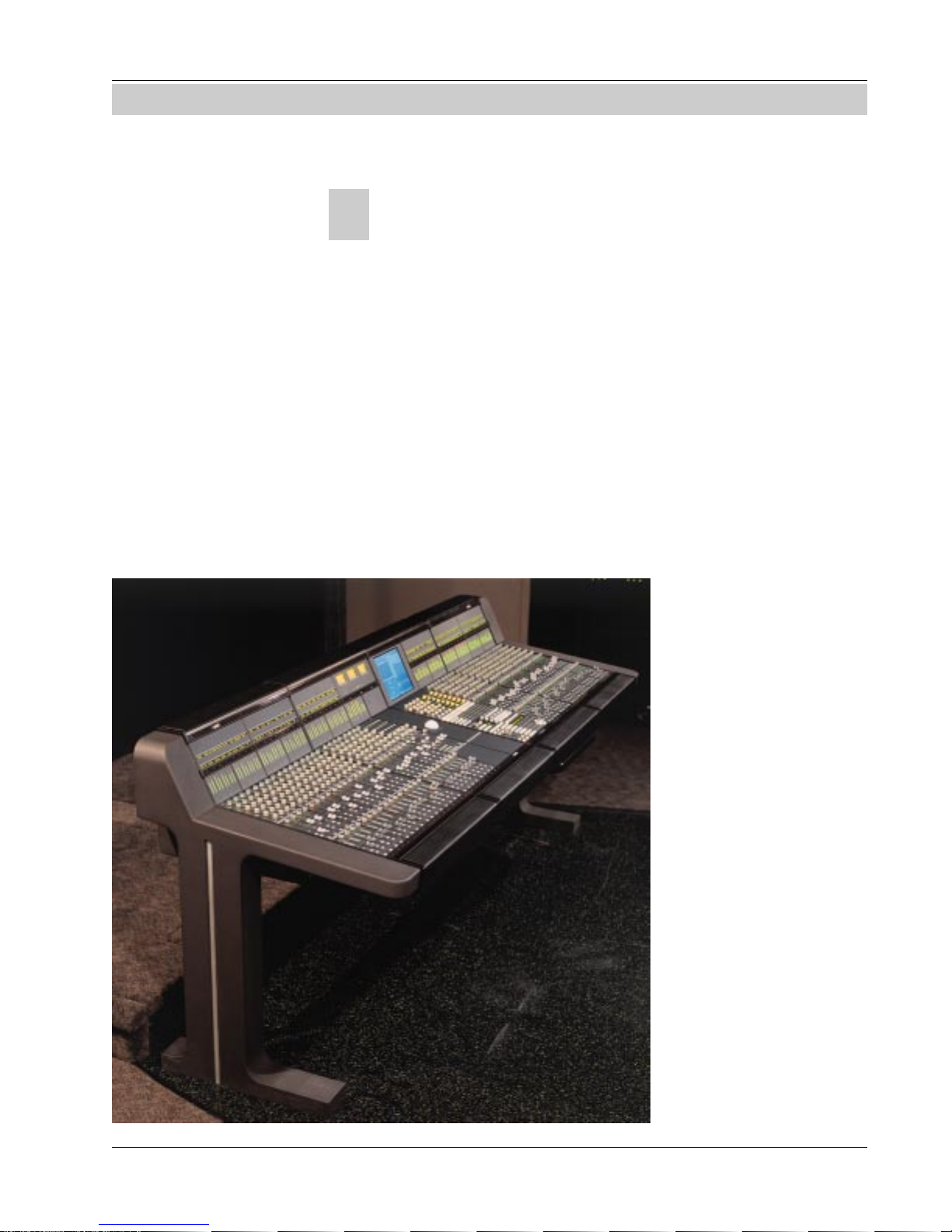
The Mix Controller resembles a conventional control surface in many ways,
with rotary controls, faders, and routing displays. However, the Mix Controller
is basically a group of computer systems working together, connected to the
remotely located Audio Tower via a multi-way serial cable snake. This snake
passes information from the Mix Controller to the electronics in the Audio
Tower. Every block of 8 faders in the Mix Controller is a computer, as is the
Master Controller and the Digital Studio Controller (DSC).
When a fader within a group of 8 faders is moved, that section’s computer
interprets the movement and sends instructions down the serial line to the
appropriate audio card. The
gain of the Digitally Controlled Attenuator (DCA)
associated with that fader is
changed by exactly the
amount the fader has moved.
In the event of a power
failure, console settings can
be retrieved from batterybacked RAM.
96-fader CS3000, model # CS3000D-4-96
Euphonix CS3000/2000 Operation Manual 1 - 3
Operation of the Euphonix is
similar to a conventional
console. However as you will
see later, there are many
incredibly powerful features
that only a system such as
this can support.
It is worth looking briefly at
the Audio Tower so you
understand what occurs
when controls are adjusted
on the Mix Controller. A
single Audio Tower can
accommodate up to 56
Page 18
Section 1: Introduction
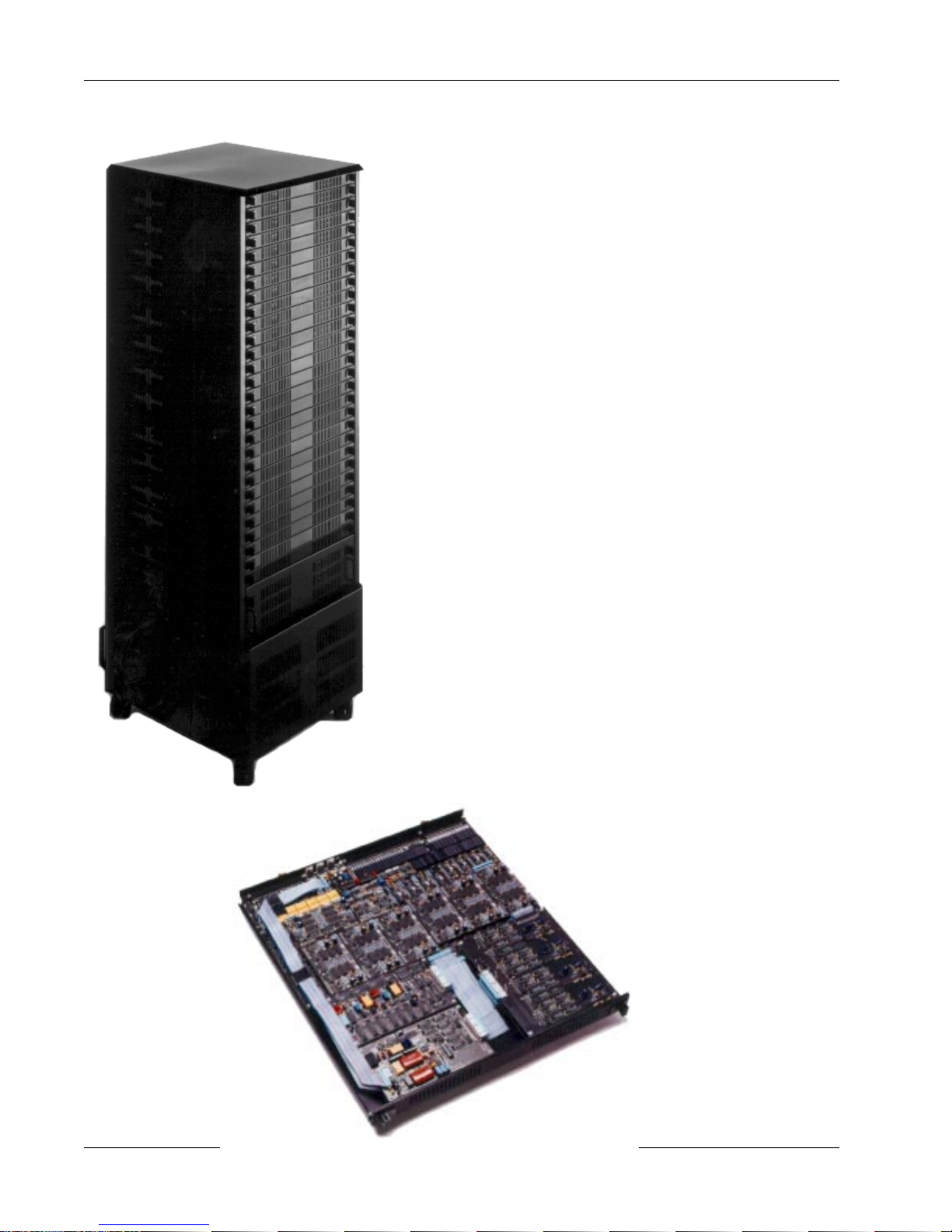
The Audio Tower
faders worth of audio. Consoles above 56 faders have two Audio Towers; the
first houses the audio electronics for 48 faders, and the second for up to 56
faders, making a potential maximum of 104 faders. The bottom 4
channel slots in the first Tower of a 2-Tower system house the
bus link cards, which bridge the audio between the two Audio
Towers. The Master Audio Module resides in the bottom of the
first Tower while the Submaster Audio Module is in the second
Tower as its Master Section.
A single I/O Audio Module includes all the analog electronics for
2 faders or 1 channel strip. Each module also includes 2 equalizers, 2 variable input amps, 4 line input amps, 3 output amps, a
stereo/dual-mono direct output, a 6-into-1 Combiner (submixer),
4 aux send gain DCAs as well as the 2 stereo fader DCAs.
As audio goes through the channel, it passes from the patchbay
to an I/O Audio Module in the Tower, and back out again to the
patchbay and/or to the various buses that run within the Tower.
This is similar to a conventional console. What is different is
that all of the controls are located remotely in the Mix Controller.
Audio Tower
Audio processing for up to 56 faders
Great care has been taken in designing the circuitry to maintain
the highest possible integrity in the audio path. Wiring lengths
are kept to a minimum; digital control signals are kept clear of
audio signal paths; high-grade components are utilized; and
each stage of the signal flow has been optimized for low noise,
low distortion, and low crosstalk.
The result is an electronically well-managed audio control
system. Since all of the analog audio circuitry is in a remote
Tower, the Euphonix Mix Controller is sleek and compact, freeing
up valuable control room real estate. The remote location of the
Audio Tower also causes the system to generate
very little heat in the control room.
I/O Audio Module
Audio processing for 2 faders
1 - 4 Euphonix CS3000/2000 Operation Manual
Page 19

The Support Computer
Section 1: Introduction
The Euphonix system includes a high-speed, 19” rack-mounted support
computer. The support computer is connected to the Mix Controller via a high
speed data link which enables it to manage all of the other computers in the
Mix Controller. It drives the screen display and the disk storage facilities as
well. During automation the support computer keeps track of all the moves
and transfers mix data to and from the Mix Controller. The computer, associated hardware and the MixView software package, is often referred to as the
MixView Platform.
In the unlikely event of a support computer failure, the Mix Controller and
Audio Tower can operate on the fly without it. Remember that within the Mix
Controller are many individual computers responsible for audio control. They
will continue to function and you will have complete control of the audio and
local snapshot store and recall functions. However, you will not have access to
automation, file management, or the screen display, since these require a
functioning support computer. Integrated Euphonix optional components like
the Audio CUBE and ES108A Dynamics also require support computer access.
MixView, the Euphonix system software, eliminates the need for a mouse,
although one is supplied for future facilities. The QWERTY keyboard is used
for naming files and can be found in a convenient sliding tray under the
CS3000/2000’s frame.
The Patchbay
The support computer also handles disk storage of mix and other information.
It has an internal hard disk and a standard 3.5” high-density floppy drive for
updating system software. Current systems are also shipped with a removable
media drive for session data import and export. All Euphonix systems are
compatible so you can track in one city and instantly reconfigure a CS3000/
2000 on the other side of the globe to exactly match where you left off.
Systems include high-quality Euphonix patchbays. As a custom option, systems may be supplied without patchbays. This is generally discouraged since
Euphonix patchbays are tested with the system to ensure signal integrity
throughout the system. The Euphonix patch system has one dual 48-jack row
for each group of 8 faders, and one for the Master Audio Module. The patchbay is enclosed in a 1U connectorized case. A 56-fader system would have
eight 1U-high patchbays. Each patchbay connects to the Audio Tower
with a high-grade multi-way cable terminated in 90-pin Elco
connectors with gold-plated contacts.
Using the Index and Table of Contents listing, this manual
Channel Patchbay
There are two 48-jack rows of halfnormalled jacks with Elco connectors on
the rear panel
Euphonix CS3000/2000 Operation Manual 1 - 5
Page 20
Section 1: Introduction
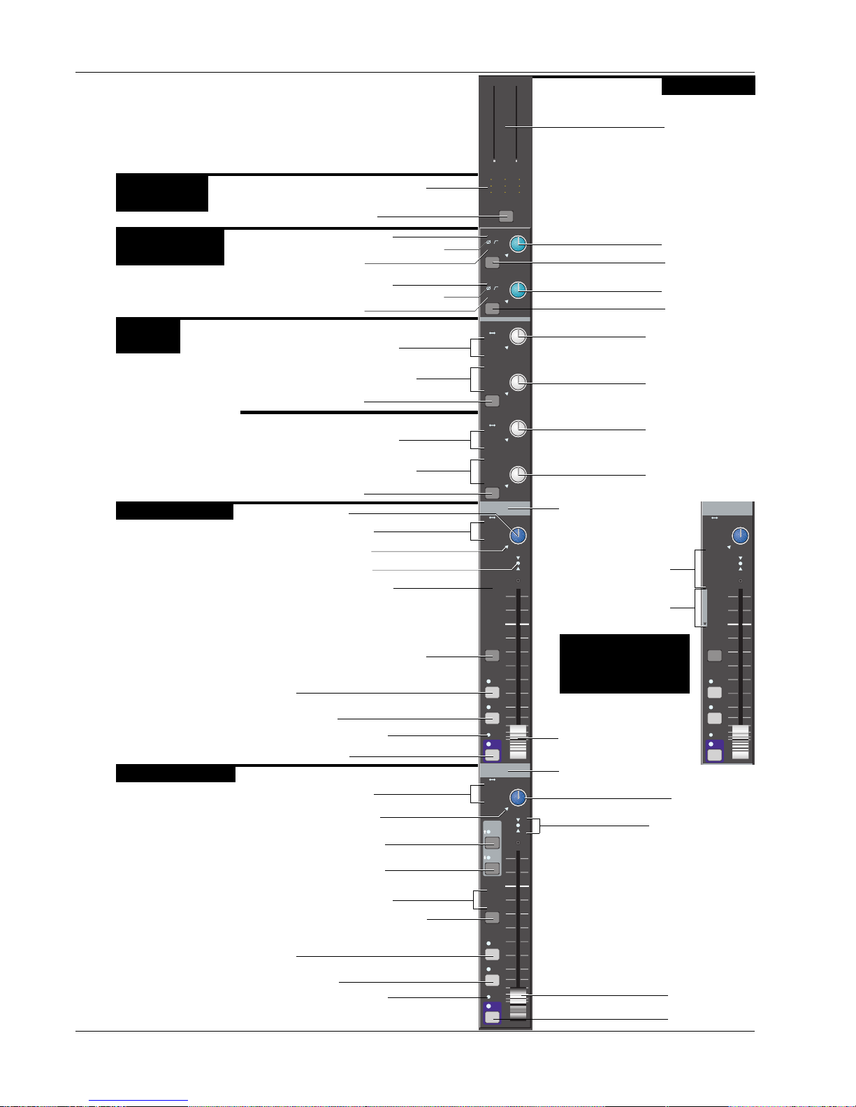
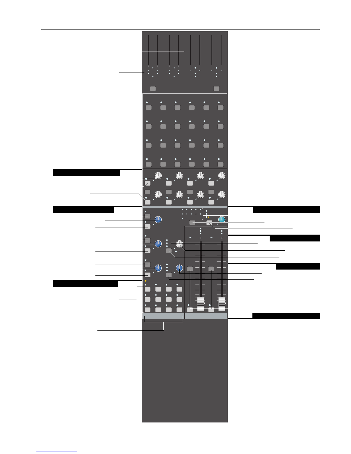
I/O Channel Module
Output Source
Select
Universal Input
Blocks, M1 & M2
Aux Send
Blocks
Upper Fader Block
Lower Fader Block
Outputs 1, 2, & 3 Source display
Channel Attention key
M1
Phantom Power indicator
Phase Rev & Hi Pass Filter indicators
Input Pad indicator
M2
Phantom Power indicator
Phase Rev & Hi Pass Filter indicators
Input Pad indicator
Aux/Cue A & B
Aux Sources A & B display
Aux Assignment A & B display
A & B Attention key
Aux/Cue C & D
Aux Sources C & D display
Aux Assignment C & D display
C & D Attention key
Pan/Bal control
Fader Source display
Pan Control Null LED
Fader Null indicators
Fader Assignment display
Upper Fader Block Attention key
PFL
AFL/Kill Solo
Group Master indicator
Fader ON (Mute)
Fader Source display
Pan Control Null LED
EQ•Dyn1 Attention key
EQ•Dyn2 Attention key
Fader Assignment display
Lower Fader Block Attention key
PFL
AFL/Kill Solo
Group Master indicator
6
0
6
3
12
0 0
18
24
3
30
6
36
42
12
48
33
60
U L
F
B
M
M
1 2
1 2
L
L
1 2
1 2
L
L
3 4
3 4
Out 1 Out 2 Out 3
M1
Pwr
Pad
ovld
M2
Pwr
Pad
ovld
A
M1 M2
L1 L2
L3 L4
ovld
BUS
A1 A2
B
A3 A4
A5 A6
A7 A8
C
M1 M2
L1 L2
L3 L4
ovld
BUS
A1 A2
D
A3 A4
A5 A6
A7 A8
Input
M1 M2
L1 L2
L3 L4
BUS
26
25
1
2
ovld
28
27
3
4
30
29
5
6
32
31
7
8
34
33
9
10
36
35
11
12
38
37
13
14
40
39
15
16
42
41
17
18
44
43
19
20
46
45
21
22
48
47
23
24
DIR
ST1
ST2
PFL
AFL
Grp
ON
Input
M1 M2
L1 L2
L3 L4
ovld
EQ•Dyn
12L
R
BUS
DIR
ST1
ST2
PFL
AFL
Grp
ON
0
6
12
18
24
30
36
42
48
60
M
L
L
PAN BAL
PAN BAL
PAN BAL
PAN BAL
6
3
3
6
12
33
1 2
1 2
3 4
Channel Block
PPM/VU meters
M1 Gain control
M1 Attention key
M2 Gain control
M2 Attention key
Aux A Send control
Aux B Send control
Aux C Send control
Aux D Send control
Fader Label strip
Upper Fader Routing
to the 12 buses
Lower Fader Routing
to the 12 buses
CS3000B, CS3000P, &
Input
M1 M2
L1 L2
L3 L4
BUS
1
2
PAN BAL
ovld
3
4
5
6
7
8
9
10
11
12
1
2
3
4
5
6
7
8
LL
9
10
F
11
12
DIR
ST1
ST2
CS3000F Upper Fader
Assign Display
Long-Throw
Automated fader
Fader Label strip
Fader Null indicators
Motorized Long-Throw
PFL
AFL
Grp
ON
Pan/Bal control
Automated fader
Fader ON (Mute)
1 - 6 Euphonix CS3000/2000 Operation Manual
Page 21
Master Module
Software Configurable Master
PPM/VU meters
Meter Assignment indicators
6
0
0
0
0
0
0
6
6
6
6
6
3
12
18
0 0 0 0 0 0 0 0
24
3
30
36
6
42
12
48
60
33
A1 A2 A3 A4
A5 A6 A7 A8
A mon B mon C mon D mon
1 2 3 4 5 6
7 8 9 10 11 12
13 14 15 16 17 18
19 20 21 22 23 24
6
3
3
12
12
18
18
24
24
3
3
30
30
36
36
6
6
42
42
12
12
48
48
60
60
33
Solo osc
33
6
3
12
12
18
18
24
24
3
30
30
36
36
6
42
42
12
48
48
60
60
33
6
6
3
3
6
12
33
L R L R
A5 A6 A7 A8
0
6
6
6
3
12
12
18
18
24
24
3
30
30
36
36
6
42
42
12
48
48
60
60
33
Ext 1 Ext 2
Section 1: Introduction
0
6
6
6
3
3
12
18
24
3
3
30
36
6
6
42
12
12
48
60
33
33
ST2ST1
8 Aux Send Master Blocks
Aux 1 Send control
Aux 1 Send ON
Aux 2 Send ON
Monitor A B & C Blocks
Monitor A Set key
Monitor A Level control
Monitor A Dim key
Monitor B Set key
Monitor B Level control
Monitor B Dim key
Monitor C Set key
Monitor C Level control
Monitor C Dim key
Monitor Source Selection
Monitor Source Selection keys
Monitor Mode keys
A1
ON
ovld
A2
ON
ovld
SET
A monitor
DIM
SET
B monitor
DIM
SET
C monitor
DIM
monitor SET
A1•2 A3•4 A5•6 A7•8
Ext 1 Ext 2 ST1 ST2
Left Right Stereo Mono
A3
ON
BAL
ovld
A4
ON
ovld
SOLO
A
B
C
Active
Solo
Ext—
C pre
D monitor
ON
BAL
ON
A1A2A3A4A5A6A7
ST1
ST2
BUS
BAL BALKill
ST1 ST2
ON ON
A5
ON
BAL
ovld
A6
ON
ovld
Oscillator
Patch
A8
TB MIC
ovld ovld
A7
BAL
ovld
A8
ovld
Talkback/Oscillator Block
Talkback/Osc Destination display
Talkback/Osc Attention key
Talkback ON
AFL/Kill Solo Block
Solo Monitor Selection display
AFL/PFL control
Solo Attention key
Monitor D Block
Monitor D Ext2 Level control
Monitor D Attention key
Each stereo output has a fader ON key
and Attention key
Stereo Output 1 & 2 Blocks
Euphonix CS3000/2000 Operation Manual 1 - 7
Page 22

Section 1: Introduction
Color Graphics
Display
Unique Dynamics & EQ display
screens provide real-time visual
display of processing status
Built-in TFT active-matrix color
graphics screen eliminates the
need for an external graphics
monitor. When adjusting EQ &
dynamics, controls on the screen
are mapped down to the
Assignable Rotary Control Set at
the top of the DSC to provide
interactive control display &
parameter indication.
Assignable Rotary
Controls
12 assignable Rotary controls
with illuminated switches can
be selected to adjust EQ,
Dynamics, Aux sends, and Bus
Masters.
Assignable Rotary control
Assignable key
Automation keys for punching
Rotary control and switches
showing Iso, Dyn, & Trim status.
Mode Select for Rotary controls
Rotary Control Mode keys
Machine Control
MIDI Machine Control of
multiple machines.
Monitor Controls
& Keys
Currently unimplemented.
Programmable Monitor Macro
keys with 8-character
Alphanumeric displays.
d t
i
d t
i
d t
i
d t
i
d t
i
d t
i
d t
i
Pg 1 Pg 2 Pg 3 Pg 4
1
3
5
Mstr
CtrlTCSlave
1
2
4
6
8
d t
i
d t
i
d t
i
d t
i
d t
i
d t
i
d t
i
DynEQ
Aux Pan
Slct
Slct
2
REC
REC
onln
onln
Slct
Slct
4
REC
REC
onln
onln
Slct
Slct
Solo
6
REC
REC
onln
onln
Route
1
2
4
6
8
d t
i
d t
i
d t
i
d t
i
d t
i
d t
i
d t
i
d t
i
1
2
3
4
5
d t
i
d t
i
d t
i
Assign
123
25
37
d t
i
d t
i
d t
i
List
Pg 1 Pg 2 Pg 3 Pg 4
Chan
45
16 17
Mon
Select
Bus
Master
!1@2#3$4%5^6&7*8(9)0_-+
Q W E R T Y U
tab
26A27S28D29F30G31H32J33K34L35
shft
38Z39X40C41V42B43N44M45
spc
6
7
8
Faders
Preset Macro
Mon
Cnfg
678
18 19 20
Rec Rec Rec Rec
Studio
9101112
21 22 23 2413 14 15
I O P
>
<
46
.
,
ComMic
Talk
Loc
continuously displays
incoming code and code type
Snapshot List showing the
50 snapshots instantly
available to the engineer by
use of the Master Control
Panel or Assignable keys
Other lists include Disks,
Projects, Titles, Mixes,
Passes, and Cue Points.
Selection is made from
SmartDisplay Function keys.
9
10
11
12
13
14
15
16
Store
Snap
Shot
=
del
:
36
"
;
'
?
48
47
/
4 Sets of Bus/Tape and Record
ent
Assignable Keys
Alphanumeric display
SnapShot Mode key
Channel Selection
Keys that can be assigned to any
individual or group of tracks.
Track & Machine indicators
Auto
Rec
The DSC
Timecode Window
8-character
Assignable key
Page Select for
Assignable keys
Mode Select for
Assignable keys
48 Routing, Solo, &
Attention keys
Record Arm key
Machine/MIDI
Transport controls
Twin Moving Faders
Twin moving faders with
Automation, Solo, & Mute keys.
You have the ability to assign
any channel to these faders for
central moving fader control &
d t
i
automation.
d t
i
32 Dedicated Keys for use
during routing and automation
to speed up access time.
Safe Safe
Solo Solo
On On
Dedicated Keys
1 - 8 Euphonix CS3000/2000 Operation Manual
GrpGrp
i
i
d t
d t
Attn Pnch Tplt Auto
Set Iso Dyn Safe
FaderAPanBOn
Trim ATO W in W out
Abs
Offset
M1 M2 DIR All
L1 L2 ST1 All
L3 L4 ST2 All
MBR Move
CD
Rec
SS
Glide
aux
upper
lower
MixOnPass
Pass
Ctrl
Grps Mtrs
Rec
Setup Snap System Grps
F1 F2 F3 F4
789
456
123
0 Enter Del
+
Bus
DIR
*
ST
Clr Esc
Master Control Panel
Dedicated Fast Access keys
SmartDisplay
SmartDisplay Function keys
Clear Current Selection
Numeric Keypad
SpinKnob for data entry
and list scroll
Page 23

This Manual
F
B
Useful Symbols
Setup Snap Auto Grps
F3F1 F2 F4
File Pass Tplate Punch
F3F1 F2 F4
Section 1: Introduction
can be used as a reference guide. However, we strongly suggest that you go
through the Tutorial, which uses examples to illustrate how the system
operates. Section 2 explains the file structure and how to save your work.
Subsequent sections then take you through operation of the whole console
using examples and exercises. Section 7 covers the automation system in
detail. Section 9 describes the operation of the software-integrated Euphonix
ES108A Dynamics unit. Section 10 describes the operation of the softwareintegrated Euphonix Audio Cube and various available multi-format bus
options and functions. The fastest way to become a fully-functional Euphonix
user is to go through the Tutorial section while sitting in front of the console.
The following are used to illustrate various concepts throughout this manual:
SmartDisplay menu. These icons are used repeatedly throughout this text to
show how to navigate through the console menu trees. Lines connecting one
SmartDisplay to another indicate movement through the menus by pressing
one of the four Special Function keys. In the example to the left, the F3 key
should be pushed in the upper menu to go to the lower menu.
+
Bus
DIR
789
456
123
0 Enter Del
F1 F2 F3 F4
SpinKnob. This icon is used to show that you can use the SpinKnob on the DSC
to cycle through available menu options in the SmartDisplay and through lists
on the screen display.
+ & – keys. These keys are often used in conjunction with or instead of the
SpinKnob to cycle through menu options and lists. These icons are an example
of how the keys on the console are represented throughout this text.
Master Control Panel Numeric keypad. This keypad is used to make menu
selections in the SmartDisplay. Note the Enter key, which often must be
pressed to confirm a numerically keyed entry. Don’t confuse this with the
keypad on a QWERTY keyboard.
Function keys on the QWERTY keyboard. These are used to choose some
system functions that only require occasional access.
M
M
M
1 2
1 2
1 2
L
L
L
1 2
1 2
1 2
L
L
L
3 4
3 4
3 4
Out 1 Out 2 Out 3
M1
Pwr
Pad
ovld
Euphonix CS3000/2000 Operation Manual 1 - 9
Console blocks. The functional control blocks that make up the Mix Controller
surface are sometimes represented by icons such as this one, which shows
the M1 Input block with gain pot, block attention key, and indicators.
Page 24

Section 1: Introduction
PWR
Line Input
Aux A
AUX BUS
1 - 8
Block diagram symbols. These symbols represent the functional blocks of
audio circuits and are used to illustrate the finer points of signal flow and
routing through the console.
Universal Input Amplifier, with phantom power, gain, phase reverse, and highpass filter
Line Input with buffer
Fader
LF
4 Band EQ
Combiner
Bus
∑
Summing
Amp
∑
Aux B
Line Out
Direct Out
Auxiliary Bus
4-Band EQ
Line Output with buffer
Direct Output with buffer
6-into-1 Combiner with summing amplifier
Bus Summer with summing amplifier
Un-normalled patch point
Half-normalled patch point
Fully-normalled patch point
SIDE NOTE:
When you try to solo wet, make
sure that the aux sends to FX
devices you are using have been
set as post-fader sends (the
default setting is pre-fader). Press
the appropriate aux block attention
key, select the mode, and then
toggle [F4] through the options to
choose either PLF (Post Lower
Fader) or PUF (Post Upper Fader).
Side Notes give solutions to potential problems and general hints about using
product features effectively.
1 - 10 Euphonix CS3000/2000 Operation Manual
Note: Throughout this manual, keys to be pressed are represented
by bold type and brackets as shown in this example: [Esc].
Page 25

The DSC
(Digital Studio
Control) Module
Digital Control
The Digital Studio Control
Module (DSC) is the central
control module that is required
to run MixView software
Versions 2.4 and later. The unit
is available to retrofit into
systems without it.
The DSC provides a highly
sophisticated integrated control
surface with built-in color TFT
display, eliminating the need for
an external graphics monitor.
Section 1: Introduction
Designed with present and
future development in mind, the
entire control surface of the
DSC is under software control.
Software updates continue to
add functionality to the surface
and extend system control for
external MIDI effects devices,
and GPI relays for fader starts,
speaker mutes, and multitrack
machines.
The Assignable Rotary Control
Set at the top of the module can
be used to adjust EQ and
dynamics parameters, Audio
CUBE aux sends, bus trims, and
multi-format panning. The DSC supports MIDI Machine Control, Assignable Moving Fader control and Assignable Keys with 8-character alphanumeric displays. The Master Control Panel (the SmartDisplay, SpinKnob, &
keypad) at the bottom right of the DSC works in conjunction with the QWERTY keyboard for Mix Controller and
support computer interface.
The flat active-matrix, 256-color screen, eliminates the need for an external monitor and becomes part of the
console surface, integrating with the Assignable Rotary Control Set at the top of the module. As part of the
surface, the screen display interacts with the DSC controls, providing the engineer with unique feedback on
system and control status which would be impossible with conventional mixing console systems. The use of
this technology enables the Euphonix to build on traditional console interfaces and at the same time introduces
a new and exciting way of controlling an entire studio as an integrated system.
Euphonix CS3000/2000 Operation Manual 1 - 11
Page 26
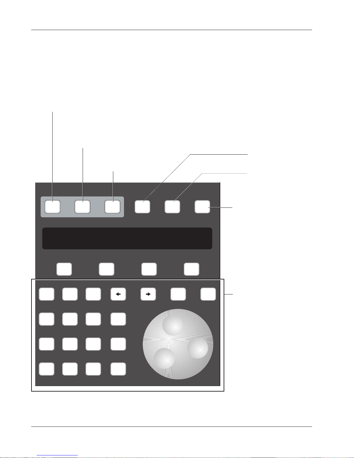
Section 1: Introduction
Master Control Panel
Switches automation On/Off
Shows when automation is ready to
record any action (replaces the REC
key on the Master Control Panel).
The Master Control Panel on the DSC is used in conjunction with the screen
display as the primary user interface for the console. The Function keys (F1,
F2, F3 and F4) below the SmartDisplay are used to access SmartDisplay
menus. The SpinKnob and +/– keys scroll through lists on the DSC screen.
Specific menu and key functions are detailed in the appropriate sections of
this manual.
Selects Group menu in
Go to Pass menu
SmartDisplay.
Selects Meter menu in
SmartDisplay
Mix
On
Pass
Rec
Pass
Ctrl
Grps Mtrs
Setup Snap System Grps
F1 F2 F3 F4
789
456
123
0 Enter Del
+
Bus
DIR
*
ST
Clr Esc
Panic Key - Allows you to
regain control of the desk in the
event of support computer
malfunction. Audio level & pan,
routing, EQ, and snapshot
functions will operate normally.
Numeric keypad, SpinKnob,
+/– keys, and other keys in
this area are used to navigate through SmartDisplay
menus and perform menuspecific functions.
1 - 12 Euphonix CS3000/2000 Operation Manual
Page 27
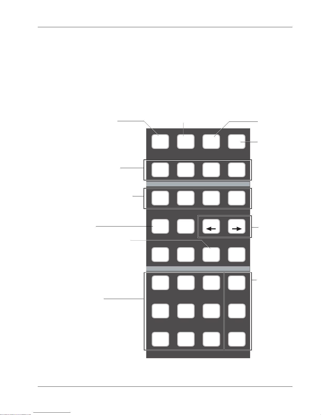
Dedicated Keys
Selects Block Key
Attention mode
Section 1: Introduction
The Routing keys in the lower left section are used to route signals through
the individual channels to various console buses. The All aux, All upper, and
All lower keys allow quick configuration of Punch and Template modes.
Others allow immediate access to automation modes such as Trim and Absolute without the need to go through menus in the SmartDisplay. These modes
are covered in detail in the Automation section.
Selects Punch mode
during automation &
selects Punch menu
Selects
Template
menu
Fast, direct access
to Template modes.
Keys used to select Fader/
Pan/Mute and Aux ABCD
controls in the Punch and
Template menus.
Selects Trim Punch mode
directly
When lit, touch punch-in
from Assignable Moving
Fader is activated.
Routing Keys.
M1, M2, L1, L2, L3, L4 allow
fast source selection.
ST1, ST2, and DIR allow fast
access when assigning faders
to their sources.
Attn Pnch Tplt Auto
SS
Set Iso Dyn Safe
Fader
A
Trim ATO W in W out
Abs
Offset
M1 M2 DIR All
L1 L2 ST1 All
L3 L4 ST2 All
Pan
B
MBR Move
On
CD
Rec
Glide
aux
upper
lower
Access Auto
SnapShot
menu
Select Punch
Extension modes
directly.
These keys are
for configuring
groups of
controls. They
operate only in
Template and
Punch menus.
Euphonix CS3000/2000 Operation Manual 1 - 13
Page 28

Section 1: Introduction
Using the
Dedicated Keys
Below are the basic functional descriptions of the Dedicated Keys. A more
detailed description can be found in the Automation section. The purpose of
these keys is to provide quick access to menu items in the SmartDisplay.
Attention Mode Key
Automation modes
change directly from
these Dedicated Keys
Used in conjunction with
Mode Change keys to
configure the template
and allow different
control combinations in
Punch mode.
Select individual
Automation Punch
control of Fader, Pan,
Mutes, and Aux ABCD
Punch Mode Key
Attn Pnch Tplt Auto
Set Iso Dyn Safe
Fader
A
Fader
A
Trim ATO W in W out
Access template on screen display
and Template menu in SmartDisplay.
SS
Pan
B
Pan
B
On
CD
On
CD
Automated
snapshot
functions
Use in conjunction
with Set, Iso, &
Dyn during automation. Also
accessable from
SmartDisplay
See the Automation section for a full description of the key functions labelled above.
1 - 14 Euphonix CS3000/2000 Operation Manual
Selects Trim mode when
running automation system
Write In, Write Out, Write
Through automation.
Page 29
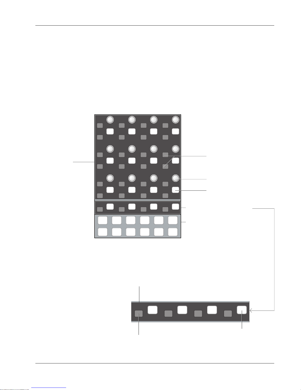
Assignable Rotary
Control Set
Section 1: Introduction
Located at the top of the DSC, the 12 continuous-turn encoder controls that
make up the Assignable Rotary Control Set are mapped to the screen display.
They are used to control EQ, dynamics, CUBE aux sends, CUBE multi-format
buses, and master CUBE bus trim levels. Each of the 12 rotary controls has a
Function key associated with it. The operation of these rotary controls and
Function keys depends on the mode selected. The actual function of both the
knob and the key is indicated by the graphics on the screen display. On some
screens only the knob is active, as in the EQ. On other screens only the key is
active, as in the dynamics Side Chain Listen key (DYN, Page 2). Sometimes
both control and key are active as in the case of Bus Master Level & Mute.
12 Assignable
Rotary Controls
and Function keys
d t
i
d t
i
d t
i
d t
i
d t
i
d t
i
d t
i
d t
i
d t
i
d t
i
d t
i
d t
i
d t
i
d t
i
d t
i
d t
i
d t
i
d t
i
d t
i
d t
i
d t
i
d t
i
d t
i
d t
i
d t
i
d t
i
d t
i
d t
i
For future development
Assignable Rotary Control
Associated Function key
4 Special Function Keys
Pg 1 Pg 2 Pg 3 Pg 4
List
Assignable Rotary Control
DynEQ
Aux Pan
Assign
Bus
Master
Chan
Select keys
The four Function keys are used for general assignable switching functions
defined by software. Their function depends on which screen is displayed.
More detailed examples are given in the following pages.
Euphonix CS3000/2000 Operation Manual 1 - 15
Automation Status Indication: Iso, Dynamic, Trim (if applicable)
d t
i
Automation Punch key
for the assignable switch
d t
i
d t
i
d t
i
Assignable
Function key
Page 30
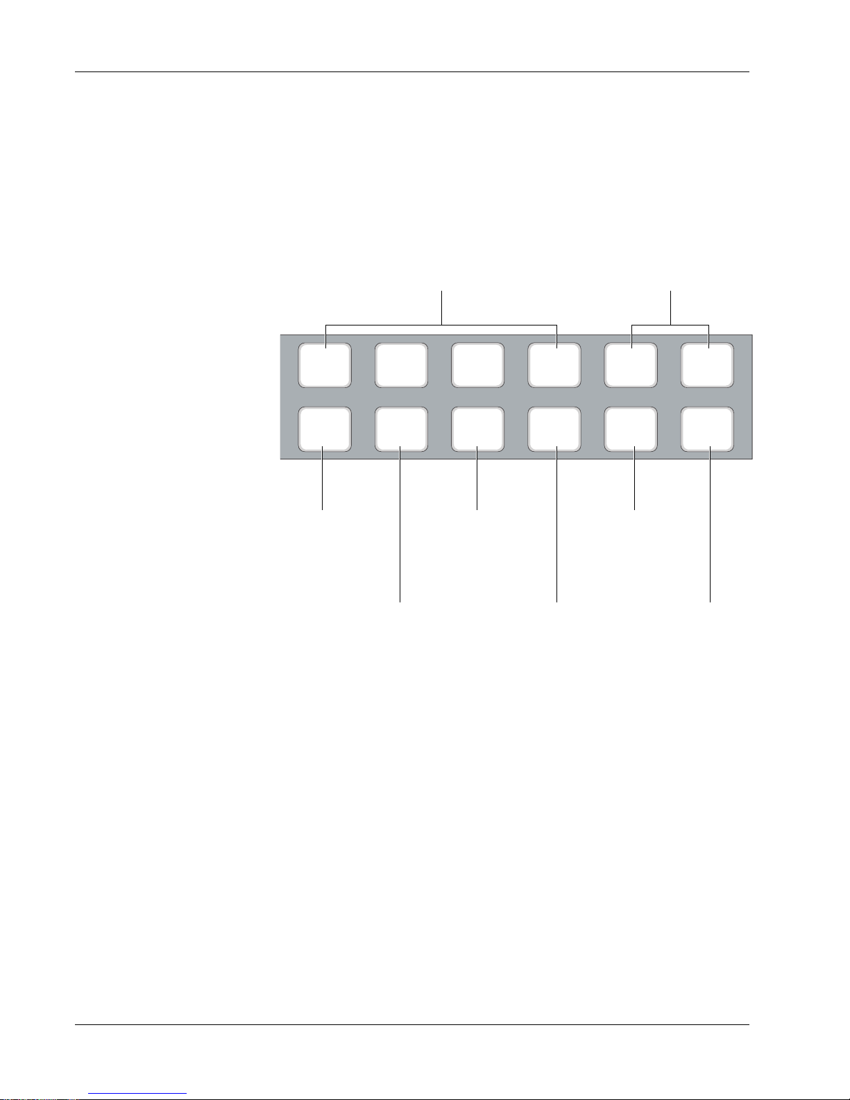
Section 1: Introduction
Mode Select Keys
At the bottom of the Rotary Assign area are the Rotary Control Select keys.
These keys select different control functions for the assignable control set,
such as EQ, dynamics, auxes, multi-format panning, etc.
Four Page keys switch between pages/screens
of functions. Sometimes only Page 1 is used.
In Dynamics mode, for example, Page 1 shows
gate/compress parameter controls and Page 2
shows filter adjustment controls.
Not yet implemented
Pg 1 Pg 2 Pg 3 Pg 4
Selects EQ
control mode
Selects ES108A
Dynamics/Filters
control mode
DynEQ
Selects Audio Cube
Aux Send control mode
Aux Pan
Selects Audio Cube
Multi-Format Bus
Panning screens &
controls
Assign
Selects Audio Cube
Bus Master control
mode for auxes or
multi-format pans
Bus
Master
List
Chan
Not yet
implemented
1 - 16 Euphonix CS3000/2000 Operation Manual
Page 31
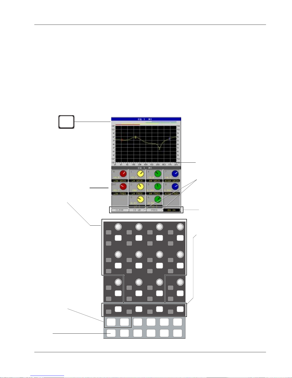
Equalizers
From the DSC
EQ
Section 1: Introduction
With the EQ mode selected from the DSC, pressing an EQ attention key
located in the lower fader block (or a DSC Channel Selection key) will cause
the EQ user interface to appear on the screen display. This includes the EQ
curve and the EQ controls and switches which are mapped down to the
Assignable Rotary Controls and Function keys. Adjusting a hardware knob
turns the virtual knob on the screen in real time, so you can see the exact
parameter value as well as see the effects of any changes on the displayed
curve, also in real time.
Just below the Assignable Rotary Controls are 4 Function keys. Their functions
are shown at the bottom of the screen. Pressing clear will zero the EQ, setting
all gains to 0 and all frequencies to their default positions. Scale range can be
switched from the default 15 dB scale to the 30 dB full scale. Scale mode can
be switched from a display in Frequency (Hz) to the same values in
Notes (as shown by 1/3rd octave
marks). The Function key on the far
right switches the entire EQ in or out
of the signal path.
Knobs are mapped as
seen on screen display.
For EQ, active knobs are
outlined here.
In the EQ screen,
Pg 1 accesses EQ1 and Pg 2
accesses EQ2
Scale Calibration and scale
Mode can be toggled. 15 dB or
30 dB, Frequency or Note
display.
Clear, scale Calibration, scale
Mode, and EQ In/Out switches
d t
i
d t
i
d t
i
d t
i
controlled by the 4 lower
Function keys. On some screens
d t
i
d t
i
d t
i
d t
i
d t
i
d t
i
d t
i
d t
i
d t
i
d t
i
d t
i
d t
i
d t
i
d t
i
d t
i
d t
i
d t
i
d t
i
d t
i
d t
i
d t
i
d t
i
d t
i
d t
i
these keys are unused.
EQ key accesses the EQ
screen
Euphonix CS3000/2000 Operation Manual 1 - 17
Pg 1 Pg 2 Pg 3 Pg 4
DynEQ
Aux Pan
Assign
Bus
Master
List
Chan
Page 32
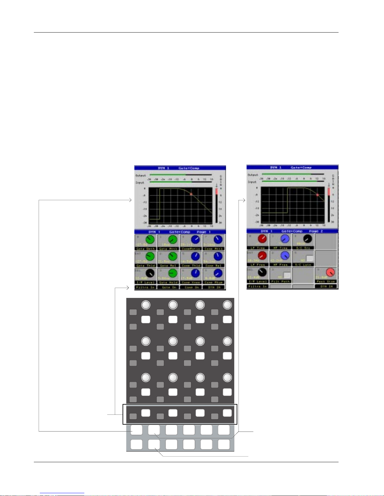
Section 1: Introduction
Dynamics
On systems equipped with dynamics, pressing the [Dyn] key will access the
Dynamics menus and screen. Now either the EQ attention key on the channel
strip or the channel selection keys on the DSC can be used to access the
assigned dynamics channel. If no dynamics are assigned to a particular desk
channel, the screen display will reflect this. Setup and assignment procedures
as well as other available modes are covered in the Dynamics section.
Depending on the Dynamics Preset selected, there may be two pages for
dynamics; using the gate/comp as an example, Page 1 is shown below left and
displays gate and compressor characteristics. Page 2 (below right), selected by
pressing the [Pg 2] key at the bottom of the Assignable Rotary Control section,
allows the filters and switching functions of the processors to be controlled.
Page 2 - Filters & Switch FunctionsPage 1 - Gate/Compressor
d t
i
d t
i
d t
i
d t
i
d t
i
d t
i
d t
i
d t
i
d t
i
d t
i
d t
i
d t
i
d t
i
d t
i
d t
i
d t
i
d t
i
d t
i
d t
i
d t
i
d t
i
d t
i
d t
i
d t
i
Special Function keys
are designated at the
d t
i
d t
i
d t
i
d t
i
bottom of the screen
Pg 1 Pg 2 Pg 3 Pg 4
List
Page 2 key switches to the
Filters screen; Page 1 back to
DynEQ
Aux Pan
Assign
Bus
Master
Chan
the Compress/Gate screen
Selects the Dynamics screen
1 - 18 Euphonix CS3000/2000 Operation Manual
Page 33

Assignable Keys
Section 1: Introduction
Situated at the top right of the DSC, this control panel has many uses. The 8character display to the left of each Assignable Key is used to tell the operator
what the function of the key is. Its function depends on what mode or page is
currently selected. Software-defined controls enable Euphonix to add new
features to any of the control sections of the console.
8-character
Display
Assignable
Key
Page keys for accessing
multiple layers within a mode
Assignable Keys
Mode select
1
2
3
4
5
6
7
8
Pg 1 Pg 2 Pg 3 Pg 4
Mon
Select
Mon
Cnfg
Preset Macro
Studio
Faders
10
11
12
13
14
15
16
9
Store
Snap
Shot
Assignable Keys are shown here in Macro mode, Page 1 (the Macro and Pg 1
keys are both lit). On this page the individual Assignable Keys are factoryprogrammed to run pre-defined macros which call up various console meter
configurations. The 8-character display indicates the meter configuration that
will be called up if the button to the right of it is pressed. Macros are NOT
user-definable, but there are a couple of files that can be auto-loaded on
bootup (access System Setup by pressing the QWERTY keyboard [F10] key and
type in the name of the factory-programmed macro file desired. V26.MAC and
CONSOLE.MAC are two files that are currently provided in MixView).
The Assignable Keys are also used for other tasks, including quick store and
recall of snapshots, monitor select for external audio device playback, and
configuration of MIDI communications.
Euphonix CS3000/2000 Operation Manual 1 - 19
Page 34
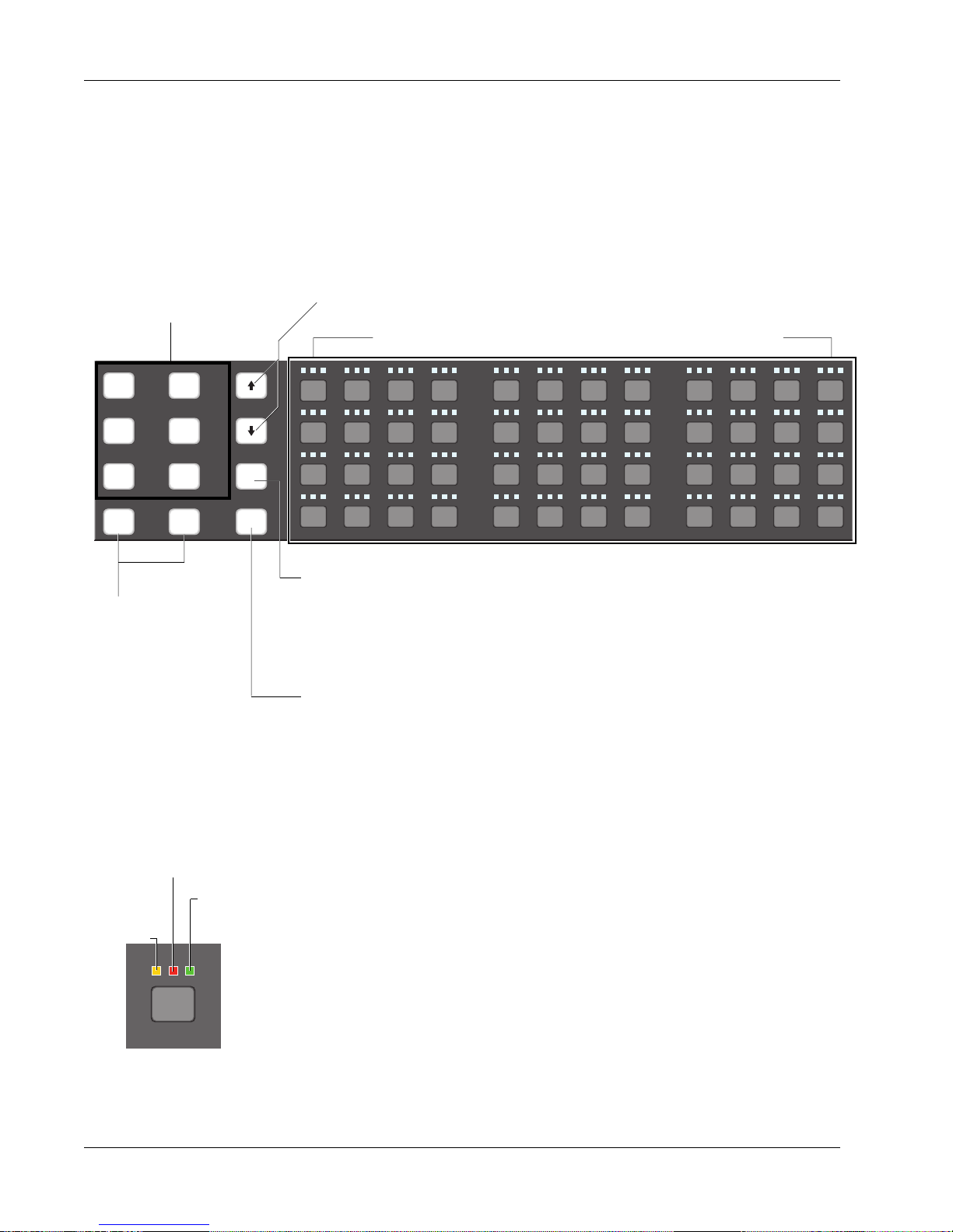
Section 1: Introduction
Channel/Route Select
Keys
Future implementation of
tape machine attention
keys for MIDI Machine
Control track arming.
The 48 numbered Select keys have multiple uses. An amber blinking LED
indicates the selected channel. After selecting a block attention key (mic pre,
aux, upper/lower fader, EQ1 or 2) on a channel strip, you can access the same
block of any other channel via these switches. For example, press channel 1’s
EQ1 block attention key. Now use these Select keys to select channel 5.
Channel 5’s EQ1 block is now displayed. Channel copying can also be done
from this location (see the Tutorial section). If no block has been selected,
these keys default to lower fader block selection.
Selects Upper or Lower faders
Select keys for Attention, Routing, Solo, and Track Arming
1
3
5
Mstr
Ctrl
Slct
REC
onln
Slct
REC
onln
Slct
REC
onln
2
4
6
TC
Slave
Slct
REC
onln
Slct
REC
onln
Slct
REC
onln
Machine Control/
Timecode Source
Select keys. Selects
various machine
control and automation slave modes.
See details in the
Automation section .
Solo
Route
!
@
#
123
1
2
3
Q W E R T Y U
tab
25
26
shft
37
spc
27
A
S
38
39
Z
X
$
45
4
16 17
28
D
40
C
%
^
678
5
6
18 19 20
29
30
F
G
41
42
V
B
&
*
7
8
31
32
H
J
43
44
N
M
(
9101112
21 22 23 2413 14 15
33
45
)
9
0
I O P
34
K
L
>
<
46
.
,
Pressing the DSC [Solo] key puts Select keys
into Solo mode. The keys can then be used to
solo upper or lower faders, as determined by
the Upper and Lower Fader Select keys.
The DSC [Route] key is used during routing to the multitrack buses.
Multitrack routing to 24 multitrack buses is done from upper faders in
a standard console configuration. Depending on jumper selection in
the Audio Tower, 12 multitrack buses can be made available to both
the upper and lower faders. CS3000P and CS3000B systems are
shipped configured with 12 multitrack buses available from all faders.
_
+
-
=
del
:
35
36
"
;
'
?
47
48
ent
/
Red LED not yet
implemented
Amber LED shows
Attention mode
Green LED
shows multitrack
assignments
Press the DSC [Route] key, and the numbered Select keys become multitrack
bus assignment keys. The bus assignments are indicated by a green LED. With
the Route key light extinguished, select channel 1 from the Select keys. Notice
the amber LED lit above key #1; press the up arrow key. Now press the [Route]
key and begin pressing 1 through 12 Select keys consecutively. Observe the
green LEDs light above each Select key that you press. Now look at channel
#
3
3
1’s upper fader. You will see the MT Assign indicator light, showing that
multitrack buses 1 through 12 are assigned.
Routing from the lower faders in 12-bus systems is accomplished in the same
way. The hidden-til-lit multitrack indicators on the faders of a standard 12-bus
console will show appropriate numbering for the buses (1-12 for upper and
lower faders instead of 1-24 for upper faders only).
1 - 20 Euphonix CS3000/2000 Operation Manual
Page 35

Track Assign Keys
Section 1: Introduction
Rec Rec Rec Rec
These keys are for future implementation. At this time the displays are used to
monitor MIDI timecode returning to the DSC. Note: this reader does not
display frames.
Transport Controls
The Transport keys are used for MIDI Machine Control of compatible tape
transports such as the Tascam DA-88™ and the Alesis ADAT™.
Auto
Loc
Rec
These keys allow the user to control external machines that support MIDI
Machine Control protocol, as well as to control the automation without
external code using the console’s VTM (Virtual Tape Machine). The MMC keys
support Play, Record, Stop, Forward, Rewind, Cycle, Shuttle, Locate to Cue,
Next Cue, Last Cue, and RollBack.
The Euphonix VTM is effectively an internal timecode generator. When the
DSC Mstr Ctrl and T/C Slave keys are off, then internal timecode can be
generated. See the Tutorial and Automation sections for additional details.
Monitor Section
Euphonix CS3000/2000 Operation Manual 1 - 21
This section is for future implementation. Currently, all monitor facilities are
controlled via the Master Module.
1
2
4
6
8
1
2
4
6
8
ComMic
Talk
Page 36

Section 1: Introduction
Assignable Moving
Faders
The Assignable Moving Faders are used for central control of any channel’s
upper and lower faders. Using the Channel/Route Select keys, or any fader
block key, gain attention of a channel strip. Now that channel’s upper and
lower faders and mutes can be controlled directly from the Assignable Moving
Faders. It is possible for the engineer to record automation fader moves and
mutes on any channel from the DSC. During automation playback, the moving
faders will track the programmed moves.
Indicates that fader
selected is an upper fader
Fader Null Indicators
Automation Punch Key
Automation Mode Indicator
(Iso, Dyn, Trim)
Mute Punch Key
Upper Fader Control
d t
i
d t
i
Lower Fader Control
GrpGrp
Indicates that fader
selected is a lower
fader
d t
i
d t
i
Mute
Note: The Assignable Moving Faders currently only work in Absolute
mode. Future software releases will enable the use of other automation modes.
1 - 22 Euphonix CS3000/2000 Operation Manual
Safe Safe
Solo Solo
On On
Page 37

M2
M1 L1
L3
L2
L4
Aux Buses
1 - 8
ST1
ST2 Solo
1
2
34567
8
9
10
1112131415
16
17
18
1920212324
ST1-L
ST1-R
ST2-L
ST2-R
AFL-R
AFL-L
PFL-R
PFL-L
22
DCA
R / even
DCA
L / odd
6:1
6:1
MT Buses
ST1-L
ST1-R
ST2-L
ST2-R
AFL-R
AFL-L
PFL-R
PFL-L
6:1
6:1
DCA
R / even
DCA
L / odd
D
DCA
A1
A2
A3A4A5
A6
A7
A8
6:1
6:1
C
DCA
A1
A2
A3A4A5A6A7
A8
B
DCA
A1
A2
A3A4A5A6A7
A8
6:1
Automated Aux Sends
A1
A2
A3A4A5A6A7
A8
6:1
A
DCA
6:1
6:1
6:1
6:1
6:1
CMB
6:1
Lo - Med - Hi
Lo - Med - Hi
CMB/M1
L4/Bus
PWR
PAD
PWR
PAD
M2/Bus
Bus Summing Amp
1-24 (bus 1 to channel1 etc...)
∑
EQ1
EQ2
M1
M2
L3
L4
L1
L2
Dir 1
Dir 2
Dir 2
Out 1
Out 2
Out 3
Dynamic Range
Dynamic Range
Processor/Emulator
Processor/Emulator
ES108
ES108
A
A
MIDI
Key Mon
246
9
121521
30
MIDI
Key Mon
246
9
121521
30
MIDI
Key Mon
246
9
121521
30
MIDI
Key Mon
246
9
121521
30
MIDI
Key Mon
246
9
121521
30
MIDI
Key Mon
246
9
121521
30
MIDI
Key Mon
246
9
121521
30
MIDI
Key Mon
246
9
121521
30
ES108A Dynamics
Out 3 & CMB
Bus/M1 switch
M2
L2
L4
MT
CMB
LFR
UFR
M1
L1
L3
CMB
MT
LFL
UFL
Right
Meter
Left
Meter
The Out 3 pre fader output is
typically used as a third insert
send paired with L3.
In the current revision of channel
electronics, the Group Bus output
can be sent to Out 3 in place of
the M1 signal freeing up the Dir 1
and Dir 2 outputs for use as post
fader feeds to the Cube.
The Dirs can be configured
as dedicated mono or stereo
post fader feeds from a lower
or upper fader.
Dynamics
Each optional dynamics
provides variable hi-
pass & low-pass filters.
Assignable EQ
Two per channel. These
EQ can remain as
individual, be cascaded
to produce an 8 band
EQ, or stereo linked.
Source - Mode - Assign
Combiner
Allows any combination
of pre fader inputs to be
sent to DIR1, DIR2 and
back into M1 input.
Dir 1 & Dir 2
Assignable Direct Outputs
Available selections are:
Group Bus Output
This is the default assignment. Dir2 typically
feeds the multitrack recorder inputs.
Bus # equals channel #.
Post Lower Fader, left and/or right.
Post Upper Fader, left and/or right.
These post fader selections are commonly used
to feed the Cube main inputs for Multi-Format
Panning, additional aux sends, or mix minus
feeds.
Combiner
Provides additional pre-fader output.
OUT 1, 2, 3
Assignable pre fader
outputs - Can be used as
insert sends or general
purpose pre-fader outputs.
1
1
2
3
448
Assignable Aux
Sends
from every fader
up to 48
Via the Cube
2
3
4
48
∑
Bus Insert
IN/OUT
Bus
Master
1 of 48
possible
Direct Bus
Inject Inputs
with link switch
The console aux
buses can be linked
into the Cube buses
integrating the two
Aux systems into one
Input
EQ•Dyn
BUS
Grp
1
2
L
R
ON
AFL
PFL
DIR
ST1
M1M2
L1L2
L3L4
ovld
PANBAL
ST2
Input
LL
F
Grp
BUS
ON
AFL
PFL
13579
11
246
8
10
12
DIR
ST1
ST2
ovld
PANBAL
M1
L1L2
L3L4
13579
11
246
8
10
12
M2
U L
B
F
633
6
12
33
633
6
12
33
0 0
0
6
12182430364248
60
0
6
12182430364248
60
CS3000D I/O Block Diagram (Rev F)
Section 1: Introduction
Euphonix CS3000/2000 Operation Manual 1 - 23
Page 38

Section 1: Introduction
M2
M1 L1
L3
L2
L4
Aux Buses
1 - 8
ST1
ST2 Solo
MT Buses
DCA
R / even
DCA
L / odd
6:1
6:1
ST1-L
ST1-R
ST2-L
ST2-R
AFL-R
AFL-L
PFL-R
PFL-L
1
2
3
4
5
6
7
8
9
10
11
12
DCA
R / even
DCA
L / odd
6:1
6:1
ST1-L
ST1-R
ST2-L
ST2-R
AFL-R
AFL-L
PFL-R
PFL-L
1
2
3
4
5
6
7
8
9
10
11
12
D
DCA
A1
A2
A3A4A5A6A7
A8
6:1
6:1
C
DCA
A1
A2
A3A4A5A6A7
A8
B
DCA
A1
A2
A3A4A5
A6
A7
A8
6:1
Automated Aux Sends
A1
A2
A3A4A5A6A7
A8
6:1
A
DCA
6:1
6:1
6:1
6:1
6:1
CMB
6:1
Lo - Med - Hi
Lo - Med - Hi
CMB/M1
L4/Bus
PWR
PAD
PWR
PAD
M2/Bus
Bus Summing Amp
1-24 (bus 1 to channel1 etc...)
∑
EQ1
EQ2
M1
M2
L3L4L1
L2
Dir 1
Dir 2
Dir 2
Out 1
Out 2
Out 3
Dynamic Range
Dynamic Range
Processor/Emulator
Processor/Emulator
ES108
ES108
A
A
MIDI
Key Mon
246
9
121521
30
MIDI
Key Mon
246
9
121521
30
MIDI
Key Mon
246
9
121521
30
MIDI
Key Mon
246
9
121521
30
MIDI
Key Mon
246
9
121521
30
MIDI
Key Mon
246
9
121521
30
MIDI
Key Mon
246
9
121521
30
MIDI
Key Mon
246
9
121521
30
ES108A Dynamics
Out 3 & CMB
Bus/M1 switch
M2
L2
L4
MT
CMB
LFR
UFR
M1
L1
L3
CMB
MT
LFL
UFL
Right
Meter
Left
Meter
The Out 3 pre fader output is
typically used as a third insert
send paired with L3.
In the current revision of channel
electronics, the Group Bus output
can be sent to Out 3 in place of
the M1 signal freeing up the Dir 1
and Dir 2 outputs for use as post
fader feeds to the Cube.
The Dirs can be configured
as dedicated mono or stereo
post fader feeds from a lower
or upper fader.
Dynamics
Each optional dynamics
provides variable hi-
pass & low-pass filters.
Assignable EQ
Two per channel. These
EQ can remain as
individual, be cascaded
to produce an 8 band
EQ, or stereo linked.
Source - Mode - Assign
Combiner
Allows any combination
of pre fader inputs to be
sent to DIR1, DIR2 and
back into M1 input.
Dir 1 & Dir 2
Assignable Direct Outputs
Available selections are:
Group Bus Output
This is the default assignment. Dir2 typically
feeds the multitrack recorder inputs.
Bus # equals channel #.
Post Lower Fader, left and/or right.
Post Upper Fader, left and/or right.
These post fader selections are commonly used
to feed the Cube main inputs for Multi-Format
Panning, additional aux sends, or mix minus
feeds.
Combiner
Provides additional pre-fader output.
OUT 1, 2, 3
Assignable pre fader
outputs - Can be used as
insert sends or general
purpose pre-fader outputs.
1
1
2
3
448
Assignable Aux
Sends
from every fader
up to 48
Via the Cube
2
3
4
48
∑
Bus Insert
IN/OUT
Bus
Master
1 of 48
possible
Direct Bus
Inject Inputs
with link switch
The console aux
buses can be linked
into the Cube buses
integrating the two
Aux systems into one
Input
EQ•Dyn
BUS
Grp
1
2
L
R
ON
AFL
PFL
DIR
ST1
M1M2
L1L2
L3L4
ovld
PANBAL
ST2
Input
LL
F
Grp
BUS
ON
AFL
PFL
13579
11
246
8
10
12
DIR
ST1
ST2
ovld
PANBAL
M1
L1L2
L3L4
13579
11
246
8
10
12
M2
U L
B
F
633
6
12
33
633
6
12
33
0 0
0
6
12182430364248
60
0
6
12182430364248
60
CS3000P/B I/O Block Diagram (Rev F)
1 - 24 Euphonix CS3000/2000 Operation Manual
Page 39
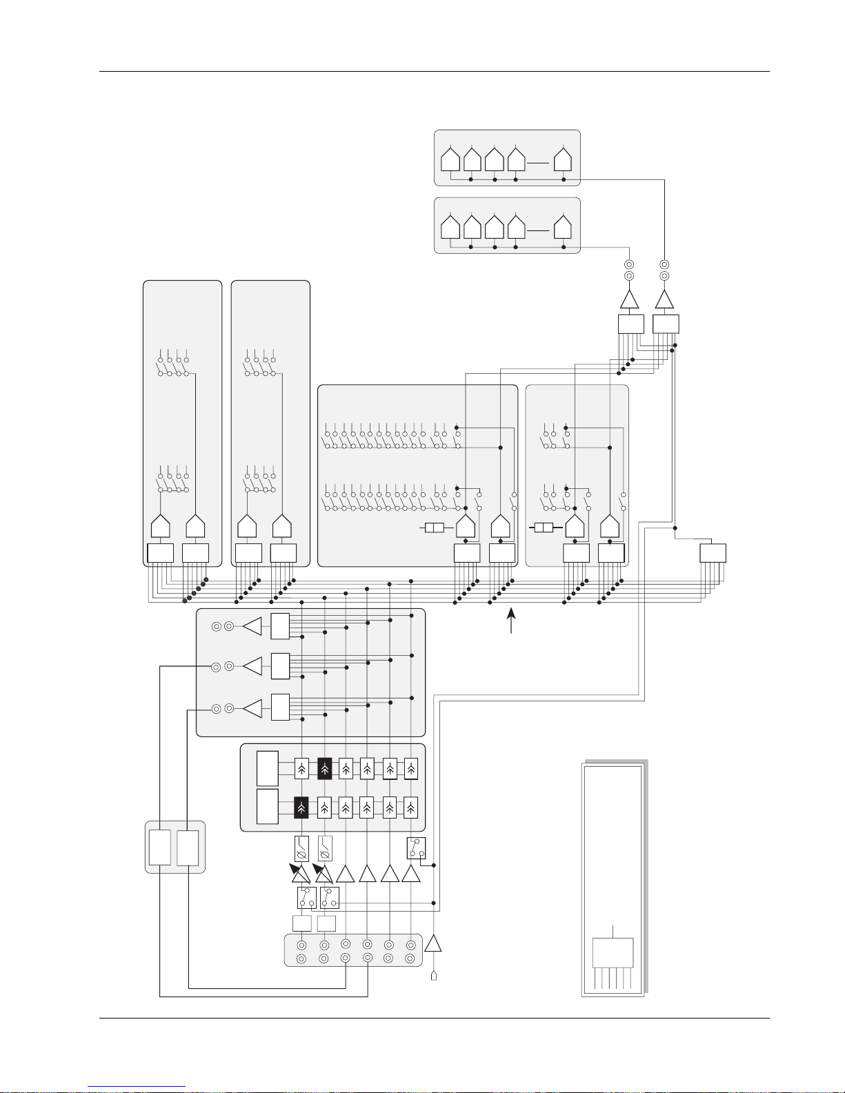
EQ2
EQ1
A
B
C
D
A1A3A5
A7
M1
M2
L3
L4
13579
11131517192123
ST2 L
Solo L
246
8
10121416182022
24
6:1
ST1 L
ST2 R
Solo R
ST1 R
6:1
6:1
ST2 L
Solo L
ST1 L
ST2 R
Solo R
ST1 R
UF
LF
6:1
6:1
BUS
1-24
6:1
OUT1
L1
OUT2
L2
1
2
3
4
48
A & B Automated
Aux Sends
C & D Automated
Aux Sends
DCA
DCA
DCA
DCA
DCA
DCA
DCA
DCA
6:1
6:1
6:1
6:1
6:1
6:1
6:1
DIR 1 & DIR 2 source assignments are:
1- The group bus summing amp for feeding multitrack
recorders. This is the default assignment.
2- Post Lower or Upper Fader for feeding Cube inputs,
providing additional aux sends, mix minus feeds, and
Multi-Format buses as shown.
3- The Combiner, providing an additional pre-fader output.
PFL
PFL
PFL
PFL
DIR2
Bus Summing Amp
1-24 (Channel 1 picks up
bus 1 etc..)
A2
A4A6A8
Combiner: Allows any
combination of pre fader inputs
to be sent to DIR1, DIR2 and
back into M1 input
M1,M2
L1,L2,L3,L4
signals post
EQ &
Dynamics
M2 & L4
have
Bus/Input
switch
Dynamics
Each optional dynamics
provides variable hi-
pass & low-pass filters
Audio Cube
Optional
Multi-Format Buses
Additional
Aux Sends, Multi-Format mix
stems, Mix Minus feeds
From 4 to 48 buses
DYN2
DYN1
A1A3A5
A7
A2A4A6
A8
DIR1
6:1
OUT3
OUT 1, 2, 3
Can be used as insert sends
or general purpose pre-fader
direct outputs
1
2
3
4
48
M1 has
CMB/Input
switch
PWR
PAD
PWR
PAD
This symbol represents a six (6)
input selector/summing circuit.
It can select and sum any
combination of the inputs.
6:1
DCA
DCA
DCA
DCA
DCA
DCA
DCA
DCA
DCA
DCA
CS2000 I/O Audio Block Diagram (Rev E)
Section 1: Introduction
Euphonix CS3000/2000 Operation Manual 1 - 25
Page 40
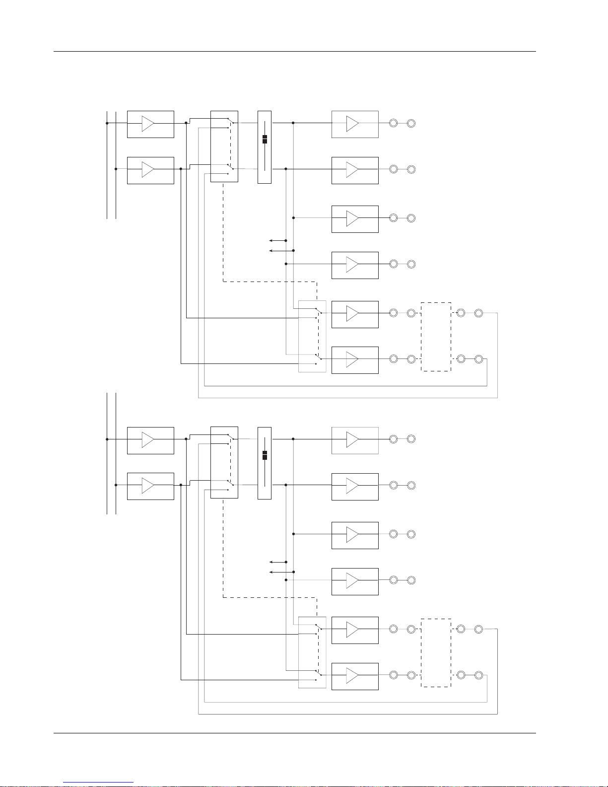
Section 1: Introduction
CS3000 Master Audio Block Diagram (Stereo Outputs)
STEREO 1 BUS
L R
BUS
∑
AMP
Bal
Out
ST1L(A)
STEREO 2 BUS
L R
BUS
∑
AMP
Pre-fader feed to
ST1 C
BUS
∑
AMP
ST1
Stereo
pre-fader
insert relays
linked together
ST1 feed to
Mon Select
& Meters
Bal
Out
Bal
Out
Bal
Out
Bal
Out
Bal
Out
Bal
Out
ST1R(A)
ST1L(B)
ST1R(B)
ST1L(C)
ST1R(C)
ST2L(A)
External
Stereo
Comp
ST1L(INS)
ST1R(INS)
BUS
∑
AMP
Pre-fader feed to
ST2 C
ST2
Stereo
pre-fader
insert relays
linked together
ST2 feed to
Mon Select
& Meters
Bal
Out
Bal
Out
Bal
Out
Bal
Out
Bal
Out
ST2R(A)
ST2L(B)
ST2R(B)
ST2L(C)
ST2R(C)
External
Effects
Device
ST2L(INS)
ST2R(INS)
1 - 26 Euphonix CS3000/2000 Operation Manual
Page 41
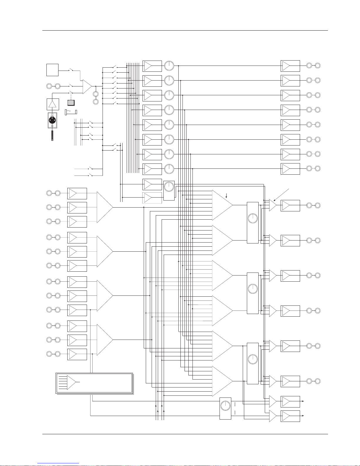
Section 1: Introduction
CS3000 Master Audio Block Diagram (Aux & Monitor Outputs)
Sine
Osc
EXT TB IN
Mic
Amp
TalkBack
Mic
MultiTrack
Bus 1-24
EXT1A L
EXT1B L
EXT1C L
EXT1A R
EXT1B R
EXT1C R
EXT2A L
EXT2B L
EXT2C L
EXT2A R
EXT2B R
EXT2C R
Talkback Select and
Feeds to Buses
∑
TB OUT
or
ST1 ST2
Bus
Odd
Even
Ext
A
In
Ext
B
In
Ext
C
In
Ext
A
In
Ext
B
In
Ext
C
In
Ext
A
In
Ext
B
In
Ext
C
In
Ext
A
In
Ext
B
In
Ext
C
In
This symbol represents a
multiple input selector/summing
∑
circuit. It can select and sum any
combination of the inputs.
Aux Bus
1 - 8
AFL/
PFL
Bus
Left
Right
∑
EXT1 (L)
∑
EXT1 (R)
∑
EXT2 (L)
∑
EXT2 (R)
∑
∑
∑
∑
∑
∑
∑
∑
∑
∑
Aux Masters
Bus
Amp
Bus
Amp
Bus
Amp
Bus
Amp
Bus
Amp
Bus
Amp
Bus
Amp
Bus
Amp
Bus
Amp
Bus
Amp
SOLO
Solo Bus
A1
A3
A5
A7
EXT1 L
EXT2 L
ST1 L
ST2 L
A2
A4
A6
A8
EXT1 R
EXT2 R
ST1 R
ST2 R
A1
A3
A5
A7
EXT1 L
EXT2 L
ST1 L
ST2 L
A2
A4
A6
A8
EXT1 R
EXT2 R
ST1 R
ST2 R
A1
A3
A5
A7
EXT1 L
EXT2 L
ST1 L
ST2 L
A2
A4
A6
A8
EXT1 R
EXT2 R
ST1 R
ST2 R
Monitor Select
(L)
∑
(R)
∑
(L)
∑
(R)
∑
(L)
∑
(R)
∑
Ext2C
Mon
D
C pre
Mon
Mon
Mon
C
AFL/PFL Select
Stereo, Mono, Left, Right Select
∑
A
∑
∑
B
∑
∑
∑
Solo
∑
∑
Bal
Out
Bal
Out
Bal
Out
Bal
Out
Bal
Out
Bal
Out
Bal
Out
Bal
Out
MON A (L)
Bal
Out
MON A (R)
Bal
Out
MON B (L)
Bal
Out
MON B (R)
Bal
Out
MON C (L)
Bal
Bal
Out
Out
MON C (R)
Bal
Out
Bal
Out
MAIN & PHASE
METER MODULE
(optional)
Bal
Out
AUX 1
AUX 2
AUX 3
AUX 4
AUX 5
AUX 6
AUX 7
AUX 8
ST1 Post Fader Feed ST2 Post Fader Feed
Euphonix CS3000/2000 Operation Manual 1 - 27
Page 42

Section 1: Introduction
This page intentionally left blank
1 - 28 Euphonix CS3000/2000 Operation Manual
Page 43

2
Section 2: Getting Started
GETTING STARTED
EUPHONIX MIXING SYSTEMS
Euphonix CS3000/2000 Operation Manual 2 - 1
Page 44

Section 2: Getting Started
This page intentionally left blank
2 - 2 Euphonix CS3000/2000 Operation Manual
Page 45

Section 2: Getting Started
SECTION 2 : GETTING STARTED
any of the controls on the CS3000/2000 are similar to those on
M
conventional consoles; faders, meters, pans, aux sends, mute
switches, etc. A big difference is the software interface displayed on the TFT
screen and the alphanumeric SmartDisplay located on the Master Control
Panel.
The Screen
The screen display acts as an extension of the console surface and interacts
Display
EQ•Dyn
Input
M1 M2
L1 L2
L3 L4
BUS
DIR
ST1
ST2
PAN BAL
ovld
12L
R
with selections on the console. For example, when you select an EQ, the
screen shows the actual EQ curve and changes in real time as EQ is adjusted.
EQ 1 M1
15
12
9
6
3
0
3
6
9
12
15
21 41 82 165 330 659 1.3K 2.6K 5.3K 11K 21K
15
12
9
6
3
0
3
6
9
12
15
Startup Screen
Blue highlighted window
bar indicates that EQ
window is active.
EQ Window Snapshot Window
When you first start up the CS3000/2000 you will notice the screen below. The
thin window bar at the top of any window list is highlighted in blue indicating
when it is active. According to this screen, there is no title or mix currently
loaded into the console.
Status Bar
Euphonix CS3000/2000 Operation Manual 2 - 3
Page 46

Section 2: Getting Started
Status Bar
Currently
Selected
Channel Fader Name
Lower
Fader
Indicator
The Status Bar is an important part of the screen display, giving the user
comprehensive system feedback in a very compact space. The symbolic nature
of the information (the use of meaningful icons, colors, etc.) gives the operator
more information at a glance. Much of the information in this diagram will be
covered in the Tutorial and Automation sections, so don’t worry about understanding everything now. This diagram is only to give you an overview of what
the graphics on the screen display represent.
SMPTE = 30 Frame
DROP = 30 Drop
EBU = 25 Frame
Current Title
Current Mix TC Display
FILM = 24 Frame
Title TailTitle Head
Status Window
Memory Bar
Yellow <90% used
Red >90% used
[Alt-M] for Memory Status
With MIX ON
Group Status
Gray - OFF
Mix Status
Gray - OFF
Yellow - ON
(MSTR/IND)
Green - ON
Red - ON + Pass Enabled
Current Pass
Gray <90 Passes
Red >90 Passes
Current Position Marker
relative to title head
and tail times
Last Recalled Snapshot
(includes Automated SnapShots)
Last Recalled Snapshot
(includes Automated SnapShots)
Pass Bar Indicator
Green - Playback
Red - Recording
During RECORD
Start Time Position
(of first punch-in)
2 - 4 Euphonix CS3000/2000 Operation Manual
# of Moves
Total number of
moves recorded
End Time Position
(of last move)
Page 47

The SmartDisplay
and Master
Control Panel
SmartDisplay
Setup Snap System Grps
F1 F2 F3 F4
Section 2: Getting Started
The SmartDisplay is located at the top of the Master Control Panel on the DSC
(See the Introduction section). The SmartDisplay tells you what each of the
four function keys (F1-F4) do if you press them. Their actions vary depending
on the menu displayed; use them to navigate through the console menus.
top-level
Main Menu
Setup Snap System Grps
F1 F2 F3 F4
789
456
123
0 Enter Del
+
Bus
DIR
*
ST
Master Control Panel
with SmartDisplay
Save Your Work
Clr Esc
789
Clr Esc
At any time, pressing the [Esc] key one or more times will get you back to this
Main menu.
From the top-level Main menu, [F1] (Setup) accesses the Console Setup
menus, [F2] (Snap) the Snapshot menu, [F3] (System) the File system & console
int/external communication menus and [F4] (Grps) the Groups menus. These
menus are covered in detail later.
Save your work on the hard disk in the support computer. The information you
save on the internal hard disk can be transferred to a removable medium for
backup or additional storage. Systems are currently shipped with a 3.5” floppy
drive and a removable cartridge drive.
It is best to begin by naming a project. Naming a new project creates a
directory (“folder”) on the support computer’s hard drive into which all your
work can be saved and later retrieved (these functions will be described later).
The computer now has a place to store your titles, which contain snapshots,
mixes, and other important console information.
MAKE A BACKUP!!!
Euphonix CS3000/2000 Operation Manual 2 - 5
The support computer effectively has 3 disk drives:
A: 3.5” high-density 1.4MB floppy drive - for updating software.
C: Internal hard drive - for saving your work.
D: Removable cartridge drive - for backups and archiving your work.
The removable cartridge D: drive is what you would normally use to transport
projects or individual titles for use in another studio, or for backup purposes.
Floppy disks may also be used to back up smaller files.
BACK UP YOUR DATA! We cannot stress this fact enough. Keep at least one
recent backup on hand in case you have any problems with your system, and
keep a second in case you have problems with the first backup. As with any
computer-based system, regular and complete backups are essential to protect
your system files.
Page 48
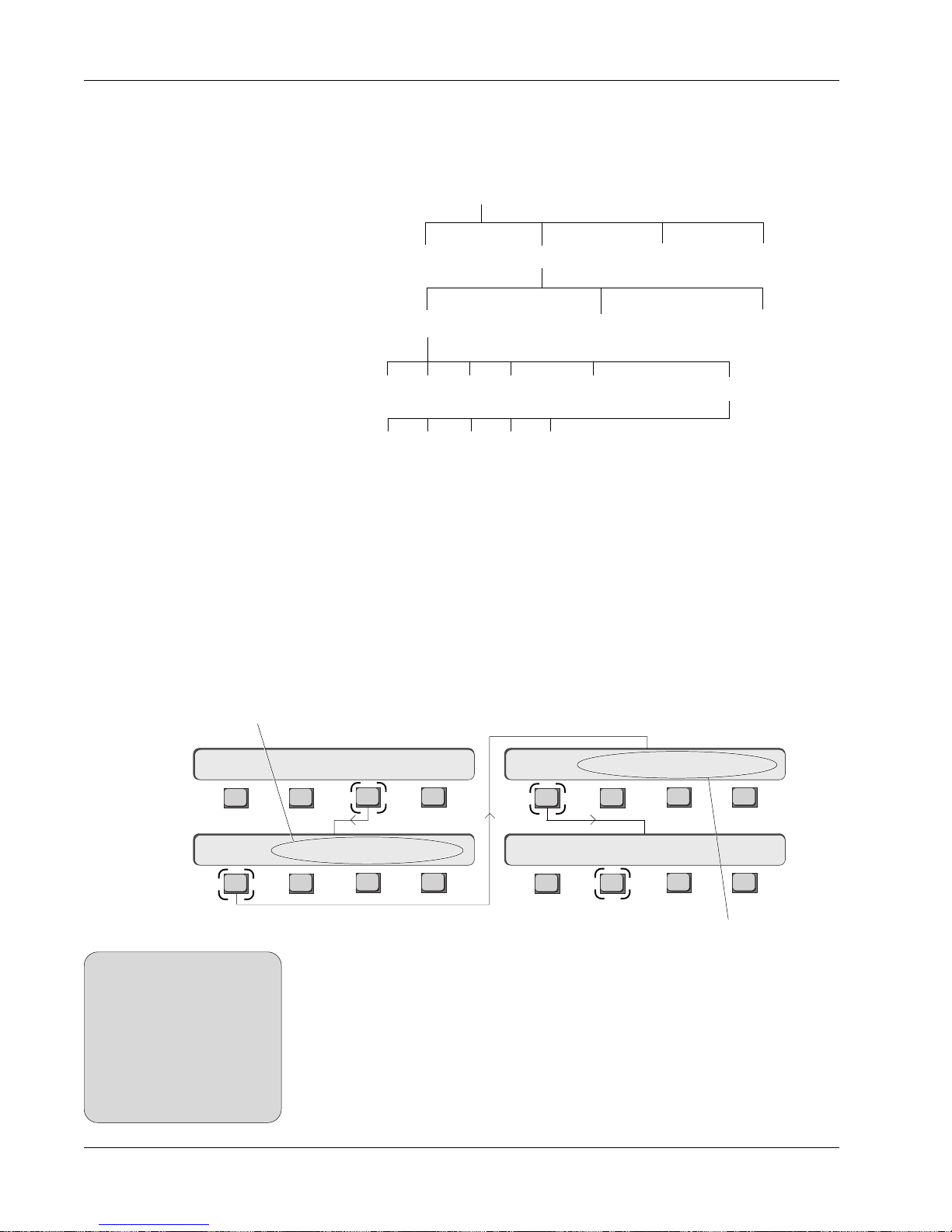
Section 2: Getting Started
File Hierarchy
Euphonix console data is organized in a basic “file system” structure. The
drives are at the top of the hierarchy, followed by projects, titles and mixes.
Remember that drive C: is the computer’s internal hard drive, that D: is the
removable disk drive and that A: accesses the 3.5” floppy:
A typical MixView
file tree:
(RAM based)
Mounting Disks
[F-Link], [GPI] & [MIDI] are used for
internal fader linking and communication
with external equipment
Disks: A: C: D:
Projects: NFL Football Surround Demo Nightly News RKK
Titles: AES NAB IBC
Mixes: #1 #2 #3 #4 Montage Final1 Montage Final2
Passes: 1 2 3 4 5…
Also stored under the title name are 50 SnapShots, title template, title setup,
ES108A Dynamics and Audio Cube assignments, MX464 Master Expander GPI
relay assignments, factory-programmed macros, comments, and cues.
The Euphonix support computer can address a SCSI drive attached to it for
storage. Normally, all computer hard disks (C: drive, etc.) appear in the Drive
list window when accessed. If you insert a DOS (IBM-compatible) formatted
removable cartridge into the D: drive, the list does not show the disk immediately. The disk must be mounted first. To do this, make sure you are at the toplevel Main menu; if not, press the DSC [Esc]ape key repeatedly, then press
[F3] (System), [F1] (File), [F1] (Disk) and then [F2] (Read):
Setup Snap System Grps
System Menu
File F-Link GPI MIDI
SIDE NOTE:
After inserting a floppy or
removable disk, make sure you
press the [F2] (Read) key,
otherwise the system will not
recognize the new disk. As soon
as you press [F2] all disks
attached to the system will
appear in the list.
Disk Project Title Mix
F3F1 F2 F4
F3F1 F2 F4
You will now see that the word ‘mounting’ appears in the
Disk list and the SmartDisplay. If the cartridge is DOS
F3F1 F2 F4
Disk: Read
F3F1 F2 F4
[Project], [Title] & [Mix] select
the appropriate lists and show
options available for that list
formatted it will appear in the list. This applies to the 3.5” floppy drive as well.
Euphonix software does not include disk format routines for floppies. You must
use pre-formatted IBM-compatible disks. You can format floppies by quitting
MixView (press [Alt-Q] on the QWERTY keyboard) and issuing the appropriate
DOS commands if you wish, but it’s simpler to buy pre-formatted disks. Refer
to the DOS manuals that came with the support computer if you need to
File MenuMain Menu
Disk Menu
format your own floppies.
2 - 6 Euphonix CS3000/2000 Operation Manual
Page 49

Project
Title
HD
unlimited
Titles*
512
Projects
50
SnapShots
200
Mixes
User
SnapShots
• Project Comments
• Project Creation Date/Time
• Title List - *limited only by disk capacity
• Title Comments • Title Setup
• Title Name • Last Mix used
• Mix List (200 Mixes)
• CS3000 • Cube
• ES108A • MIDI
Title Setup
Info
ES108A:
includes: Dynamics assignments
AUDIO CUBE:
includes: Bus Names Buses (48)
Panner Names Panner Panners (16)
Aux Names Aux Buses (48)
Cube Configuration
MX464 MASTER EXPANDER:
includes: Setup Data
CleaR DISPLAYS:
includes: Upper Fader Names Lower Fader Names
MISC:
includes: GPI Fader assignments MIDI in/out
Head/Tail times MIDI Program changes
TOD/Input TC MIDI SnapShot linking
Cue TC position/name TC frame standard
Cue List (999 Cues)
Mix
Automation
Mix Setup
Info
Mix
SnapShots
• Automation Database (1000 Passes)
• Automation Templates (CS3000)
• CS3000 • Cube
• ES108A • MIDI
• Mix Comments • Mix Setup
• Mix Name • Last Mix used
• Last Mix update Date/Time
• Auto SnapShots (999 SnapShots)
• Punch Templates • Punch Modes
• Groups
System Data
Organization
Section 2: Getting Started
Euphonix CS3000/2000 Operation Manual 2 - 7
Page 50

Section 2: Getting Started
List Selection
You can change the currently selected list by invoking the Disk list. From the
top-level Main menu, press [F3] (System), [F1] (File), [F1] (Disk) and then [F2]
(Read):press [F1] (Disk):
Main Menu
System Menu
Setup Snap System Grps
File F-Link GPI MIDI
Disk Selection
Disk drive list now selected
(will be highlighted in blue)
C: disk now selected
Disk space used on the
selected disk
Clr Esc
+
Bus
DIR
*
ST
SpinKnob or [+]/[–] keys are used
to scroll through the selected list
File Menu
Disk Menu
F3F1 F2 F4
F3F1 F2 F4
Disk Project Title Mix
F3F1 F2 F4
Disk: Read
F3F1 F2 F4
Remember: Pressing the [Esc] key moves
you back up the menu tree one level
Notice the selected window is shown by the highlighted blue title bar above
the list. You can select different disks with the DSC [+]/[–] keys and the
SpinKnob. In this case,
the floppy drive (A:) is
not visible because
there is no floppy
inserted into the drive.
Select the C: disk. The
Project list to the right
of the Disk list now
shows the projects
that are on the C:
drive. As you scroll
through the disks you will see that the Project list changes showing the
projects on each disk. Notice that when a disk is selected the computer reads
from it and then displays projects and titles. There will be a slight delay before
the projects and titles are displayed after you stop scrolling; this interrupt
enables you to scroll smoothly through the list without having to wait for each
lower-level list to update. Lists can be displayed sorted chronologically (by
date) or alphabetically. (See “System Setup” in the Appendix section.)
Projects
A project contains only titles, nothing else. It defines and gives a name to the
space on the disk in which your titles are stored. Titles are the files that
contain the actual session information. Before doing anything else, create a
project so there is a defined area on the disk in which to save your work.
Although you can operate the system without saving, it is so easy to save and
retrieve your work that it makes no sense to operate without having named a
project and title into which your valuable mixes and snapshots can be stored.
2 - 8 Euphonix CS3000/2000 Operation Manual
Page 51

New Project
Section 2: Getting Started
Go to the File menu. If you are in the Drive menu at the top of the last page,
simply [Esc]ape back up to the File menu. Press [F2] (Project):
File Menu
Project Menu
The Project Bar is highlighted in
blue showing that the window
is currently active
Disk: Project Title Mix
F3F1 F2 F4
New? ReNm? Del? Copy?
F3F1 F2 F4
Press [F1] to create a new project. You will be prompted to name your new
project. The project name could be the record, film or TV series, or could
represent an individual operator’s user space. The project name can be up to
eight characters in length. Upon naming the project, the current date and time
is automatically assigned to the project. Notice that the title list is empty since
you have not yet named a title. (See Naming a Title later in the section)
The window will look something like this:
Date and time project was created
Currently selected project
Comments field for the project
Project Comments
You can enter a project’s Comments field by pressing the [Tab] key on the
QWERTY keyboard. You can type in up to 4 lines of remarks in the Comments
field. Pressing [Tab] again gets you back to the Project list. You can return to
the Comments field at any time to update your comments.
Euphonix CS3000/2000 Operation Manual 2 - 9
Page 52

Section 2: Getting Started
Rename Project
You can rename a project from the File menu by pressing [F2] (Project), [F2]
(ReNm?) and then [F3] (Yes) to confirm:
Disk Project Title Mix
Delete Project
SIDE NOTE:
As with renaming projects, a
project containing titles
currently in use cannot be
deleted.
New? ReNm? Del? Copy?
F3F1 F2 F4
Rename Proj? Yes [No]
F3F1 F2 F4
F3F1 F2 F4
Project MenuFile Menu
A prompt on the monitor screen will allow you to type in a new name (up to
eight characters for a project). When done you can press the keyboard [Enter]
key or [F3] (Yes). Pressing [F4] ([No]) will abort the renaming of the project.
Note that you cannot rename a project that contains titles currently in use.
To delete a project, go to the Project menu and press [F3] (Del?). You will be
prompted for confirmation in the SmartDisplay:
Delete Proj? Yes [No]
F3F1 F2 F4
!! Danger !! This will delete all enclosed titles as well as associated
SnapShots and mixes within the project file. To prevent accidental
deletion, the screen prompt requires you to press the QWERTY keyboard [Enter] key or [F3] (Yes) in the SmartDisplay for confirmation.
Copy Project
Project Menu
Copying a project will copy every title within that project. Since the number of
titles is limited only by available disk space, and each may contain up to 200
mixes, a project’s size can be very large. If you try to copy a project to a disk
with insufficient space, an error message will tell you that the copy was
aborted. You may want to limit the size of your project to avoid potential file
management problems, since DOS limits how large a single directory can get.
From the Project menu, press [F4] (Copy?) to copy a project:
New? ReNm? Del? Copy?
F3F1 F2 F4
Copy to Disk ? [OK]
F3F1 F2 F4
You now have to select a disk drive on which to copy the currently selected
project. Notice that the Disk list header is highlighted in blue and that the
current drive is selected. If you want to copy the entire project to the same
drive, press [F4] ([OK]). If you want to copy to a different drive, select the drive
in the Disk list using the SpinKnob or DSC [+]/[–] keys and then press [F4].
2 - 10 Euphonix CS3000/2000 Operation Manual
Page 53

Section 2: Getting Started
The following menu appears:
Copy Proj ? Yes [No]
F3F1 F2 F4
…together with a screen prompt so that you can rename the project before
you make the copy. If you intend to
copy back to the current drive then
you must rename the project. If you
try to copy the project to the same
disk as a project with the same name,
the copy process will automatically
abort. If you’re copying to the another
drive, you don’t need to rename the
project. Press [F3] (Yes) to proceed or
[F4] ([No]) to abort.
The use of screen prompts along with
SmartDisplay questions is common in
the Euphonix system and mainly used
when you need to type something
from the QWERTY keyboard.
Titles
The titles contain all the important session information. Projects are simply
designated storage areas (like folders in Windows or Macintosh operating
systems). An example of a typical Title window, showing the titles contained
in a project is shown below. (See “Titles and Files” in the Appendix section for
a breakout of all system files found on the CS3000 system hard disk.)
Title Window:
Date and time of
title creation
Comments
Window
Euphonix CS3000/2000 Operation Manual 2 - 11
Page 54

Section 2: Getting Started
Title Hierarchy
Disk A: Floppy Disk C: Internal HD Disk D: Removable
Project 1-Synclav 2 Project 2-DEMO II Project 3-RKK
Title 1 The Montage Title 2 AES Paris Montage Title 3
Reebok Demo
Audio Cube Assignments
Dynamics Assignments
MX464 GPI Relay Assignments
Comments
Setup
Cues
Macros
Snapshots (50)
Mixes
All this is saved
with the title
MixTitle
Current title and mix are
displayed in the Status Bar
New Title
Mix 1
Snapshot
Template
Dynamic moves (passes)
Mix 2 - Current Mix
Snapshot
Template
Dynamic moves (passes)
Mix 3
Snapshot
Template
Dynamic moves (passes)
From the File menu, press [F3] (Title), then [F1] (New) to create a title in your
new project:
File Menu
Disk Project Title Mix
F3F1 F2 F4
New? Load? Save? Utils
Loading a title
also loads the
last current mix
with its SnapShot
& template
A window will appear on the screen display allowing you to name your new
title. Enter the name of the title by typing in the keyboard and then press
[Enter].
2 - 12 Euphonix CS3000/2000 Operation Manual
F3F1 F2 F4
Page 55
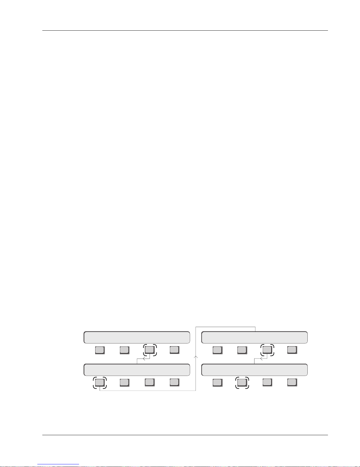
Title Comments
Section 2: Getting Started
You can enter comments about a particular title by pressing the Tab key when
the title has been highlighted. When in the Comments field, simply type in
your comments and press Tab again to exit. To move between titles when in
the Title list, use the SpinKnob or the DSC [+]/[–] keys.
What’s in a Title?
Save Title
Now that you have a title you can start to work and save what you do. When a
new title is created, the current set of snapshots in the console gets saved to
the new title’s SnapShot list.
Every title contains:
50 Snapshots - Up to 50 snapshots are stored with each title. The Snapshot
list is shown on the right-hand side of the screen display.
Audio Cube - Bus allocations, bus names, bus linking and inserts, and I/O
switch settings.
Dynamics - Assignments of CS3000/2000 channels to ES108A channels.
MX464 Master Expander - GPI relay assignments.
Mixes - Up to 200 mixes can be stored within a title.
Cues - Up to 999 cue points can be used to place and view events.
Macros - These function keys allow a single button press to carry out a
number of factory-programmed actions.
Title Setup - Time display type, timecode type, Head & Tail times, etc.
Comments - User comments pertaining to the title.
At any time you can save the current title by going to the Title menu and
pressing [F3] below the SmartDisplay. This saves anything in the title that you
may have changed since the last save such as snapshots, comments, cues,
etc. When you save a title that has mixes and you have made changes to the
mixes, a prompt will come up on the screen asking if you would like to save
the changes. If you reply “yes”, changes are saved to the mix, its SnapShots
and automation templates. The next time you load the title, it will load the last
mix and bring back that mix’s snapshot and template.
Load Title
Main Menu
System Menu
Euphonix CS3000/2000 Operation Manual 2 - 13
Setup Snap System Grps
File F-Link GPI MIDI New? Load? Save? Utils
The diagram below shows how to get to the Title menu from the top-level
Main menu. Press [F3] (System), [F1] (File), [F3] (Title) and then [F2] (Load?) to
load a title:
File Menu
Title Menu
F3F1 F2 F4
F3F1 F2 F4
Disk Project Title Mix
F3F1 F2 F4
F3F1 F2 F4
Page 56

Section 2: Getting Started
SIDE NOTE:
When a title is loaded the last
saved mix of that title is also
loaded and the console is reset
with the mix’s snapshot &
automation template.
Now select another title using the SpinKnob or the DSC [+]/[–] keys. When the
desired title is highlighted in the list, press [F2] to load it. You will be
prompted with the following menu:
Load Title ? Yes [No]
F3F1 F2 F4
The monitor screen will also show a prompt. To load the selected title, press
[F3] or the [Enter] key on the DSC Numeric keypad. Pressing [F4] or [Esc]cape
will abort the title load. Note that when you load a new title, you will lose
whatever title information is currently in the desk.
The newly selected title’s 50 snapshots will now be loaded into the console’s
memory, ready for instant access, together with the mix that was in memory
when the title was last saved. If the title did not have any saved mixes, an
“untitled mix” is loaded. As you load a title, the last mix is loaded together
with the last mix snapshot and template.
Loading a title usually takes less than a minute (unless there is quite a lot of
automation data) allowing you to move quickly between songs, shows or
whatever you do. Remember that you cannot
load
a project, as the project is
simply a directory area for storing your titles.
Title Utilities Menu
Disk Project Title Mix
Title Utilities Menu
Title Rename, Delete
and Copy
There are a few more file management features to explore before you move on
to the SnapShot Recall section of this manual. These features include renaming and copying titles. You may need to refer back to this section of the
manual when you want to create, copy, rename or delete a project or title or
save files to a removable cartridge. Some of these file utilities are accessed
from the SmartDisplay Util menu or from the keyboard function keys.
We have already looked at the Title menu’s New, Load and Save commands.
Now let’s look at the Utils options. From theFile menu, press [F3] (Title) and
then [F4] (Utils):
New? Load? Save? Utils
F3F1 F2 F4
ReNm? Del? Copy? Setup
F3F1 F2 F4
F3F1 F2 F4
Title MenuFile Menu
Function keys [F1], [F2] and [F3] allow titles to be renamed, deleted and
copied. The interface is exactly the same as with projects. Use the Copy
command when backing up your title to the removable disk drive. After
selecting Copy, you will be prompted to select the destination disk and project
folder for the copy in exactly the same way as you had to select the disk for
copying a project.
2 - 14 Euphonix CS3000/2000 Operation Manual
Page 57

Section 2: Getting Started
When the currently selected title is copied, you will be given the chance to
rename the title before the copy is made. You cannot rename a title that is in
use. You cannot copy a title to a disk without a project name on that disk.
Make sure to create a project on a disk before attempting to copy to that disk.
Backing Up Titles onto a
Removable Cartridge
Title Setup Menu
789
456
Title Utilities Menu
To make a backup copy of a title on a removable cartridge:
1. Insert a DOS, preformatted removable cartridge in the D: drive.
2. Go to the Disk menu; press [F2] to perform a disk read.
3. Create a new project on the removable D: disk .
4. Go back to into the original project and select the title you wish to back
up.
5. Select Title Copy [F3] from the Title Utility menu.
6. At the ‘Copy to Disk?’ prompt select the D: drive with the SpinKnob or the
DSC [+]/[–] keys.
7. At the “Copy to Proj?” prompt select the project name on the removable
disk drive that you want to copy the title into using the SpinKnob or DSC
[+]/ [–] keys.
8. Press [OK] to confirm and make the copy, renaming the file if necessary.
The final menu in the File System menus is the Title Setup menu. Access this
by pressing [F4] from the Title Utility menu (see previous page, last menu). A
window opens showing current settings on the screen.
The SmartDisplay allows you to set various options which are stored with the
selected title. From the Title Utilities menu, press [F4] (Setup):
ReNm? Del? Copy? Setup
F3F1 F2 F4
123
0 Enter Del
Key in the timecode number,
followed by [Enter]
T/C Display
T/C Standard
Current Position
Marker
Title Head
Title Tail
Pass Bar Indicator.
Shows the location of the
current automation pass Start
and End times in relation to the
Head and Tail of the title.
Title Head 00:00:00
F3F1 F2 F4
You can use [F1], [F2], the SpinKnob or the DSC [+]/[–] keys to toggle through
the options so you can set parameters:
Title Head - Sets a start reference TC address used by the Current Position
Marker displayed in the TC Display, (upper right corner of the DSC display
screen). Using the Numeric keypad, enter the timecode value that you wish the
display to reference from, followed by the DSC [Enter] key.
Title Tail - Sets an end reference TC address used by the Current Position
Marker. The head and tail times need not be exact; they are only used for the
start and end points in the Pass Control window. Locate to Head is an option in
the Cue list. Represented by a green or red line along the bar, it is used during
automation so that you can see what part of the title was changed.
Film o/s - Sets a TC offset number which is applied to film’s incoming
feet|frames reference in order to sync your mixes to film.
Euphonix CS3000/2000 Operation Manual 2 - 15
Page 58

Section 2: Getting Started
T/C Standard - Allows the timecode type to be changed manually although
the type will automatically be selected after reading incoming timecode for a
couple of seconds. A manual change is useful if you want to perform off-line
editing and need to change the timecode type to match a particular standard.
With incoming timecode from a multitrack or video reference generator, the timecode type will automatically be selected and displayed in
the upper right hand corner of the DSC display screen
[F3] and [F4] toggle through the options: Film 24, EBU 25, SMPTE 30, Drop
Frame.
TC Display - [F3] and [F4] toggle between hh:mm:ss display or Day/Time
display.
. The Function keys
Mixes
Mixes contain all automation data. The file management menus for mixes are
similar to those for projects and titles; you will find Utility menus allowing
mixes to be renamed, copied, and deleted. (See the Automation section for
more about mixing.)
2 - 16 Euphonix CS3000/2000 Operation Manual
Page 59

3
Section 3: SnapShot Recall
SNAPSHOT RECALL
EUPHONIX MIXING SYSTEMS
Euphonix CS3000/2000 Operation Manual 3 - 1
Page 60

Section 3: SnapShot Recall
This page intentionally left blank
3 - 2 Euphonix CS3000/2000 Operation Manual
Page 61

Section 3: SnapShot Recall
SECTION 3 : SNAPSHOT RECALL
efore even attempting to look at signal routing you should learn how
B
the SnapShot Recall system operates. This is one of the most powerful
features of the console and it will completely change the way you approach all
aspects of mixing.
All controls and switches on the console may be stored to any one of 50
memory locations within a title. They can then be instantly recalled to reset
the entire console. EVERYTHING is stored from the channel strip (and almost
every function on the Master Control Module) including fader levels, pan
position, EQ settings, aux send levels, routing, etc. The only things that don’t
get saved as part of the SnapShot are monitor configurations, solo configurations, and some other settings that are more logically stored with the mixes.
See page 3-10 for details.
If you are learning the system you may wish to save your tutorial work. Section
2 detailed how to name a project and title so you can work on the console and
save your SnapShots for access at a later session. If you don’t do this, any
changes you make to the SnapShots will be lost when another title is loaded.
In Section 4 there is a full tutorial on routing. It is quite useful to save your
routing experiments into SnapShots as you go through the tutorial.
The Master
Control Panel
Master Control Panel on DSC
Find the Master Control Panel at the bottom of the DSC. This is the main
control area in the console and is conveniently located nearest to you in the
center-position monitor sweet spot for that very reason.
The diagram below shows the Master Control Panel. The alphanumeric
SmartDisplay tells you what the four Function Select keys ([F1] to [F4]) directly
below it will do if you press them. At any time, pressing [ESC] one or more
times will return you to the Main menu shown in the Master Control Panel’s
SmartDisplay below:
MixOnPass
Setup Snap System Grps
F1 F2 F3 F4
789
456
123
0 Enter Del
Pass
Ctrl
+
Bus
DIR
*
ST
Grps Mtrs
Clr Esc
Returns you
step by step
back up the
menu
hierarchy
Rec
Euphonix CS3000/2000 Operation Manual 3 - 3
Page 62
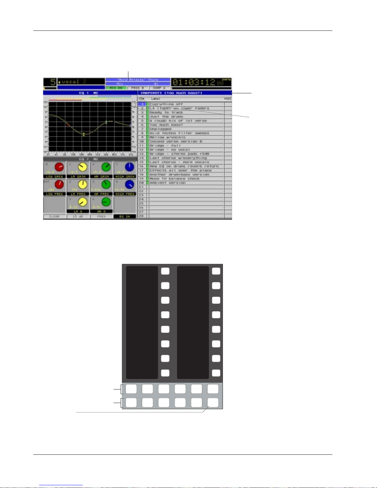
Section 3: SnapShot Recall
Interactive Screen
Display
The list in the right half of the screen lists the SnapShots in the console. When
a new title is created and named (see Section 2), the current set of console
SnapShots is stored in the the new title.
Currently Selected Title
Currently Active SnapShot
SnapShot selected in SmartDisplay ready for recall.
As you change the SnapShot
number, the highlight bar
will move up and down the
list. In this example,
SnapShot #1 shown highlighted here is the same
SnapShot that is currently
active as well.
Recalling (RCL) a
SnapShot
Assignable keys
(seen in SnapShot
mode)
Page keys
Mode keys
SnapShot
Mode key
SnapShots are recalled via the DSC Assignable Keys or the Master Control
Panel. When you recall a SnapShot, the entire console is reset in less then one
SMPTE frame (1/30th of a second).
1
9
You have one-button recall of all 50
SnapShots from the DSC Assignable
2
3
10
11
keys located in the upper right of the
DSC. The SnapShot name will appear
in the 8-character display to the left
4
12
of the Assignable key. Using the Page
keys located below the bank of 16
5
6
13
14
Assignable keys, you can page
through the 50 SnapShots 16 at a
time. Press the [SnapShot] Mode
7
8
Pg 1 Pg 2 Pg 3 Pg 4
Faders
15
16
Store
key. Now select any one of 4
SnapShot pages by pressing a Page
key. Now press the Assignable key to
the right of the desired SnapShot
number to instantly recall it.
Mon
Select
Preset Macro
Mon
Cnfg
Studio
Snap
Shot
Note that SnapShot selection using
the DSC SnapShot keys or the DSC [+]/[–] keys is a destructive process that
“clears” all console settings by loading another SnapShot. For non-destructive
SnapShot list scrolling, use the SpinKnob to highlight a stored SnapShot
location on the screen and press [F4].
3 - 4 Euphonix CS3000/2000 Operation Manual
Page 63
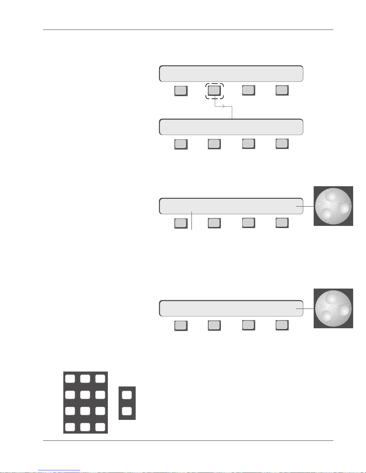
Section 3: SnapShot Recall
SnapShot Mode
SpinKnob
To get to the SnapShot Recall menu from the Master Control Panel, simply
press [F2] (Snap) in the Main menu of the SmartDisplay. You are now in
SnapShot mode.
Setup Snap Auto Grps
F3F1 F2 F4
**SS=1 a RCL 1
F3F1 F2 F4
Turn the SpinKnob and you will see the number on the far right end of the
SmartDisplay change. You can spin to any number from 1 to 50. These represent the 50 SnapShot Recall memories in the current title. Pressing [F4] will
instantly recall the selected SnapShot.
**SS=1 a RCL 1
Numeric keypad,
[+]/[–] keys
789
456
123
0 Enter Del
F3F1 F2 F4
The number in the left of the display is the most recently recalled SnapShot.
Move the SpinKnob until 11 shows in the right side of the SmartDisplay, then
press [F4]. SnapShot 11 will recall and the desk will instantly reset to whatever is stored there (note that you lose current console settings if they are not
saved). Also, the number to the left will update to show that 11 is now the
current SnapShot.
**SS=11 a RCL 11
F3F1 F2 F4
You can also go to a particular SnapShot memory location by entering the
number on the keypad. To select SnapShot 27, press the [2] key, then the [7]
and then the [Enter] key. This is the same as using the SpinKnob to get to a
number. When you press [F4] the desk resets to SnapShot 27.
The [+]/[–] keys next to the SpinKnob will reset the console to the next
+
Bus
DIR
SnapShot up (+) or down ( – ) from the current number shown in the
display above F4. The only difference with these keys is that each time
you press the key, the SnapShot memory resets the console without
having to press F4. This is invaluable for sequential SnapShot recall in
live performance work.
Euphonix CS3000/2000 Operation Manual 3 - 5
Page 64
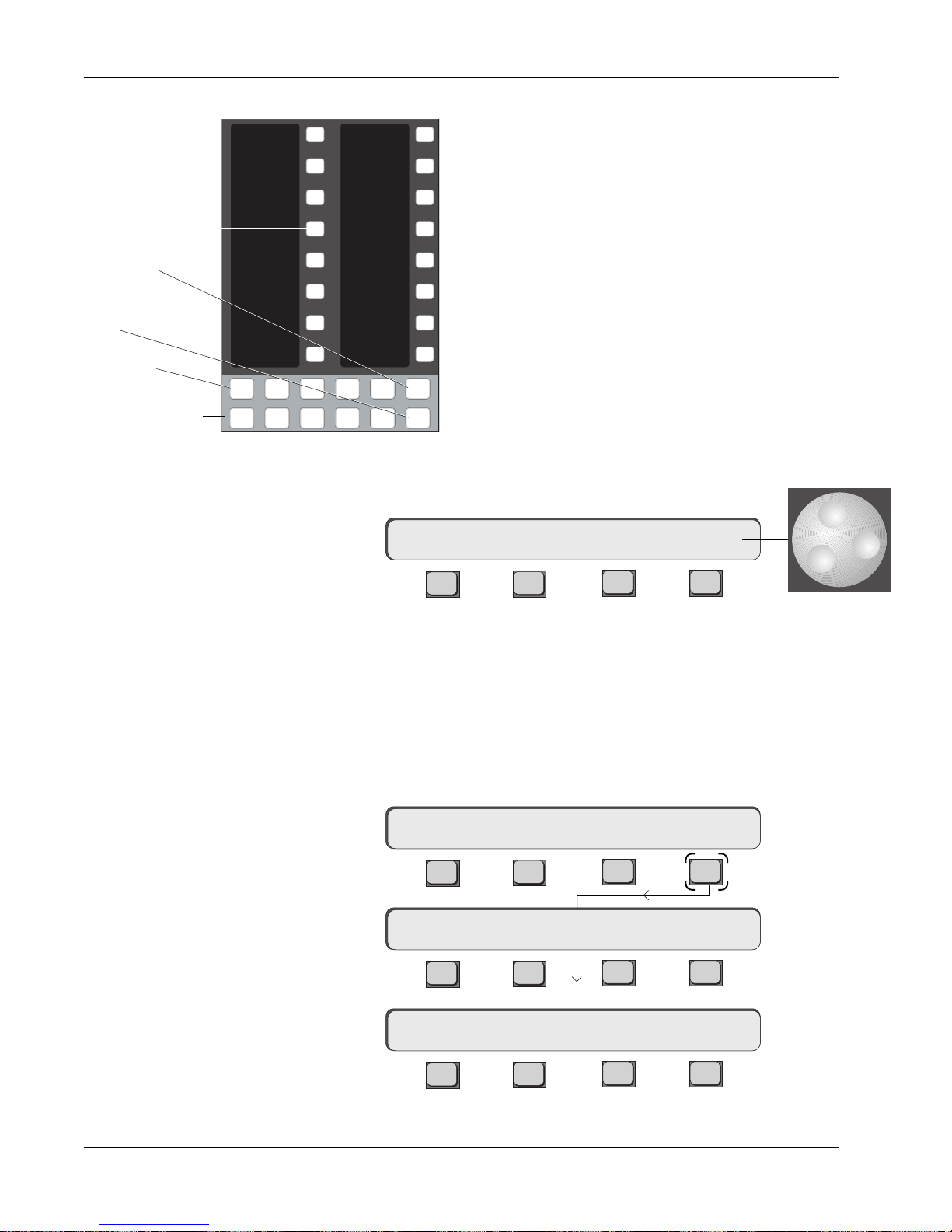
Section 3: SnapShot Recall
Storing (STO) a SnapShot
1
DSC Assignable
keys
SnapShot Assignable key
Store key
SnapShot Mode
key
Page key
Assignable keys
Mode Select
Using the Master
Control Panel
Pg 1 Pg 2 Pg 3 Pg 4
Mon
Select
2
3
4
5
6
7
8
Preset Macro
Mon
Cnfg
Studio
Another way to store a SnapShot is to use the Master Control Panel. Use the
SpinKnob or the numeric keypad to select 16 in the display above F4.
SnapShots can be stored using the DSC Assignable
Keys or the Master Control Panel. From the DSC Assign-
9
10
11
12
13
able Keys section, press the SnapShot mode key. This
puts the Assignable Keys in SnapShot mode. Next press
the Store key and name your SnapShot from the keyboard, then select the SnapShot page (Pg 1-4). Each
page displays 16 SnapShots except Page 4 which
displays 49 & 50 and the Default, Auto Null On/Off, and
Physical keys. Store the SnapShot to a specific
Faders
14
15
16
Store
Snap
Shot
SnapShot number by pressing the corresponding
Assignable Key. For example, to store console settings
into SnapShot memory 16, press the [Snap]shot Mode
key, the [Store] key, name the SnapShot, press the [Pg
1] key and then press the #16 SnapShot Assignable Key.
This procedure saves the current state of the console to
SnapShot memory #16.
**SS=11 a RCL 16
IMPORTANT!
Next press [F3]. This toggles between Store (STO) and Recall (RCL) as indicated above [F3]. It also brings up a prompt on the screen display so you can
enter the name of the SnapShot from the keyboard. It is possible to save the
SnapShot without naming it. Press [F4] to store.
Make sure STO not RCL shows in the display above F3 before you press F4 or
you will lose your SnapShot! You can also press the [Enter] key instead of F4
to store the current console into the SnapShot indicated above F4.
Momentary display:
Then:
Press [F4]:
F3F1 F2 F4
**SS=11 a STO 16
F3F1 F2 F4
...SnapShot STORED 16
F3F1 F2 F4
**SS=16 a RCL 16
The current desk has now been stored to 16. Note that the left number now
indicates that 16 is the active SnapShot and [F3] has returned to RCL.
3 - 6 Euphonix CS3000/2000 Operation Manual
F3F1 F2 F4
Page 65

Section 3: SnapShot Recall
B
IMPORTANT!
A red box in the SnapShot list on the DSC screen, indicates that the adjacent
SnapShot is stored in the Mix Controller’s RAM only. The new SnapShot will
not be saved to disk until you save the title. When you are finished with a title,
Color of box indicates whether
SnapShot has been saved
Rename a SnapShot
save the title and all SnapShot data will be saved to disk (subsequently
indicated with a green box). Recalling another title without saving the previous
title first, will overwrite any SnapShot data added since the last title save.
To rename a SnapShot, first select the SnapShot number, then press the [F1]
key on the QWERTY keyboard. This brings up an entry dialog on the DSC
screen. Type in the new name and press the [Enter] key.
Single Channel
The two asterisks (**) shown in the left of the SmartDisplay indicate that the
SnapShots are working globally, i.e., EVERY control and switch on EVERY
SnapShot Recall
channel and the Master Section will be recalled or stored. Only the functions
listed on page 3-12 are not included in the SnapShots. SnapShots can also be
recalled or stored on a channel by channel basis. For example, while still in
Global SnapShot mode, recall SnapShot 1. The SmartDisplay appears like this:
Press [F1] to enter Single Channel SnapShot mode:
**SS=1 a RCL 1
F3F1 F2 F4
M
L
L
M1
12
12
34
M
L
L
12
12
34
Channel
Attention
key
??SS–> a RCL :
F3F1 F2 F4
You are now in Single Channel mode. The display asks you to select a
channel. Press the channel attention key at the very top of the channel strip
you wish to affect. We will use channel 5 for this example. The selected
channel number will now show in the left of the SmartDisplay where the ??
M
12
L
12
L
34
Out 1 Out 2 Out 3
Pwr
was, followed by the SnapShot number currently active in that channel.
Pad
ovld
5SS–>1 a RCL :1 ok
F3F1 F2 F4
Using the Assignable Keys, SpinKnob or numeric keys, select SnapShot #10.
Make sure you’re in Recall (RCL) mode above F3. Using the Assignable Keys
All other channels will
won’t require pressing F4.
5SS–>10 a RCL :10 ok
maintain their current
settings while channel 5
F3F1 F2 F4
is updated to the
settings stored in
SnapShot location #10.
You have now copied the contents of SnapShot 10 into channel 5 exclusively.
Notice that the number following the “SS” updates to show that SnapShot 10
is now active in channel 5. Press [F1] to return to Global SnapShot mode.
Euphonix CS3000/2000 Operation Manual 3 - 7
Page 66
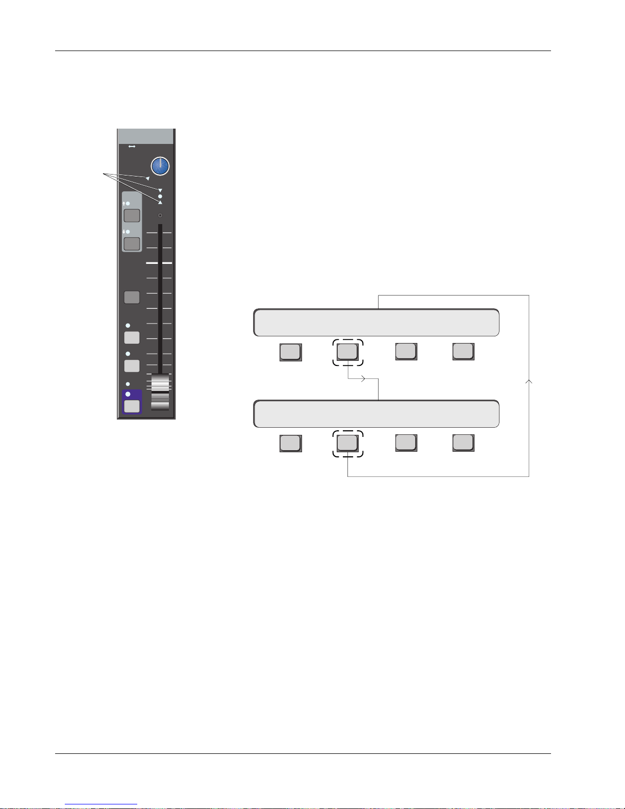
Section 3: SnapShot Recall
Nulling Controls
Standard Faders
Input
Null
indicators
M1 M2
L1 L2
L3 L4
EQ•Dyn
12L
BUS
DIR
ST1
ST2
PFL
AFL
PAN BAL
ovld
R
When a SnapShot is recalled you will notice a number of red indicators on the
console light up. As you recall a SnapShot, the audio electronics in the Tower
instantly reset to match the SnapShot audio levels. These levels may be
different from the actual physical positions of the controls, in which case a red
“null” indicator lights up next to the control. At this point the audio is under
computer control. Green means a control is aligned with the computer level
and red means the control is not aligned.
Try recalling any SnapShot that lights one of the fader red null indicators. Go
to that fader and move the fader in the direction of the red arrow. As the fader
passes through the null point, control is regained and the red indicator will go
out (in Auto-Null mode only – see below).
There are two options available for nulling recalled controls; Manual Null and
Auto Null. These modes can be switched from the DSC Assignable Keys (see
bottom of page 3-10) or by pressing [F2] from the SnapShot menu. This toggles
between the different modes:
Auto Null
**SS=10 a RCL 10
F3F1 F2 F4
Grp
ON
Manual Null
**SS=10 m RCL 10
F3F1 F2 F4
The “a” indicates Auto Null, “m” indicates Manual Null.
In Auto Null, the fader or knob automatically regains control of the audio when
it passes through the null point. For fader nulling, the red arrow indicates
which direction the fader needs to be moved to reach the null point.
With Manual Null, the fader null indicator goes green when the fader matches
the audio. You must press the block key to regain control of the nulled fader.
For fast operation the Auto Null option is better. The Manual Null mode is
most useful when you just want to exactly match all the faders to the
SnapShot position. When you have moved the faders to the null, rather than
having to hit all the individual block keys, you can simply switch to the Auto
Null mode. When you move the faders away from the null they will automatically activate.
Motorized Faders
In some instances, nulling does not operate as described above when used
with motorized faders. See the motorized faders portion of the Automation
Section for more information.
3 - 8 Euphonix CS3000/2000 Operation Manual
Page 67
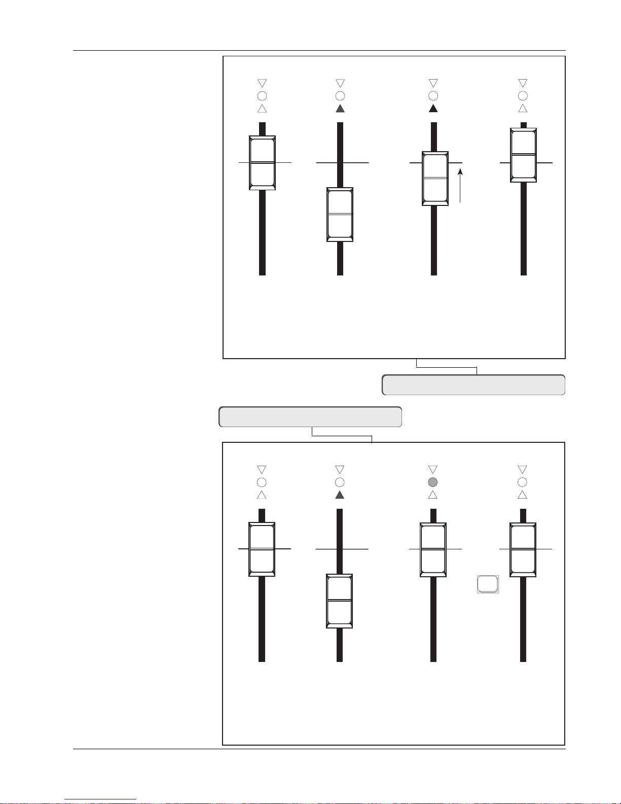
Section 3: SnapShot Recall
Auto Null Selected (a)
Red
Green
Red
Store
Snapshot
Fader AutoTakeover from a Snapshot
Recall Snapshot.
Fader has been moved
so RED indicator
shows direction the
fader has to be moved
to reach the null point.
Fader is disconnected
from audio.
Move fader
towards the null
position shown by
the red arrow.
As the fader passes
through the null
point, control is
automatically
regained and the
fader becomes
active. The red
indicators go out.
Manual Null
Selected (m)
* Nulling requires
pressing the block key
m = Manual Null*
**SS=11 m RCL 11
Fader Nulling - Manual Null Mode
Red
Green
Red
Store
Snapshot
Recall Snapshot.
Fader has been moved
so RED indicator
shows direction the
fader has to be moved
to reach the null point.
Fader is disconnected
from audio.
**SS=11 a RCL 11
a = Auto Null
Fader Block
Key
Move fader to the
null position shown
by the green
indicator.
Press the Block Key to
null and restore control
to the fader. All indicators
go out.
Euphonix CS3000/2000 Operation Manual 3 - 9
Page 68

Section 3: SnapShot Recall
PAN BAL
The same nulling laws apply to rotary controls as faders, although the red
indicator does not show the direction of the null point. When the control
passes through the null point the red LED goes out and the rotary control is
now active.
Each time you recall a SnapShot, it is not necessary to null every control. You
will instantly hear the recalled settings. Null a control only if you need to
modify an audio level.
Zeroing the Desk
CLEAR All
SnapShot
Memories
!!CAUTION!! When in the SnapShot Mode, pressing the Default key in Page
4 of the DSC Assignable Keys (see diagram bottom of page) or pressing the
M1 assignment key on the Master Control Panel will allow you to zero the
desk. It will deselect all routing and turn down every gain control. Try this to
see the effect. Many of the controls will show a red indication since their
physical position will now be different from the actual audio settings.
!!EXTRA CAUTION!! When in the SnapShot menu, pressing [Clr] followed by
[F3] will allow you to completely clear the SnapShot memory. It will not reset
the desk, so all of your current routing and levels will remain intact. This can
be useful if you want to create a new title, clear out the SnapShot memory
and store the current desk settings as the first SnapShot.
In both cases, as a precaution against totally destroying a good mix, the
SmartDisplay will ask if you are sure you want to do this. You need to confirm
by pressing [F3] (Yes). If you wish to abort, press [F4] ([No]) or press [Esc].
**SS= Sure? Yes [No]
F3F1 F2 F4
Match Current
A simple way to make the audio level match the current physical position of
the controls and faders is to press the Assignable Key labelled “Physical” in
Position
page 4 when in SnapShot mode. Instantly, all null indicators go out indicating
that the audio levels now match the position of the controls. This can also be
done from the Master Control Panel. Press the ST* button in the Master
Control Panel keypad.
DSC Assignable
Keys Section
1
49
2
50
3
4
5
6
7
8
Pg 1 Pg 2 Pg 3 Pg 4
Pg 1 Pg 2 Pg 3 Pg 4
Mon
Mon
Select
Select
Preset Macro
Mon
Preset Macro
Mon
Cnfg
Cnfg
Studio
Studio
DEFAULT
PHYSICAL
AUTONULL
Faders
Faders
9
10
11
12
13
14
15
16
Store
Store
Snap
Snap
Shot
Shot
Recall Default
(Zero) SnapShot
Match levels
to Controls
Toggle Auto/Manual
Null Mode
Master Control
Panel keypad
+
Bus
DIR
*
ST
Match
3 - 10 Euphonix CS3000/2000 Operation Manual
Page 69

Section 3: SnapShot Recall
Auto-Backup
Main Menu
Setup Menu
Setup Snap System Grps
Backup Interval Menu
Normally if the power fails while you are working on a computer-based
console, you might lose changes made since you last saved your settings.
However, the Euphonix has a built-in automatic backup system which stores
the entire console to battery-backed RAM on a regular basis. You can set the
frequency of this auto-backup procedure from the Console Backup menu. If you
ever need to recall the backup SnapShot it is also done via this menu. From
the Main menu, press [F1] (Setup), [F2] (Cnsl), [F4] (Backup) and then [F2] (Int):
F3F1 F2 F4
Mstr Cnsl Meter MFdr
F3F1 F2 F4
backup interval : 5 min
This is the time between auto-backups. The time interval can be changed by
keying in a new number using the numeric keypad, or by stepping up and down
with the DSC [+]/[–] keys. The range is 1 to 99 minutes.
Backup: Int Rcl
F3F1 F2 F4
Macs Cnfg Diag Backup
F3F1 F2 F4
F3F1 F2 F4
Console Menu
Backup Menu
Recalling the
Backup SnapShot
Press [Esc] once to get to the Backup menu.
Backup: Int Rcl
F3F1 F2 F4
If your studio experiences a power failure, or if you do something catastrophic,
like recalling a SnapShot when you meant to store it (see page 3-4), you can
recall the last auto-backup.
From the Backup menu, press [F3] (Rcl) to enter the Recall Auto-Backup menu:
RCL backup SnapShot ?
F3F1 F2 F4
Pressing [F4] will now restore the last backup SnapShot. Press [Esc] once to
get to the Backup menu:
Backup: Int Rcl
Euphonix CS3000/2000 Operation Manual 3 - 11
F3F1 F2 F4
[F4] is for future use and is not active in current software revisions.
Page 70

Section 3: SnapShot Recall
The backup SnapShot is taken in the background while you work. It is worth
mentioning that the shorter your interval time is, the less time you have to
recall the SnapShot should you need to. If your interval is set to 1 minute and
you experience a power failure, once the power is restored you have only 1
minute to recall your backup SnapShot before it is updated again. Of course,
setting the interval too high has the obvious disadvantage of allowing the
operator to lose more work in this scenario.
Isolate During
SnapShot Recall
Items NOT Stored
as part of
SnapShot Recall
The new template system described later in this manual allows parts of the
console to be isolated from SnapShot Recall. Any sections of the console that
have been configured in Isolate (yellow color on the template screen) will not
change when a SnapShot is recalled. This very useful feature is ideal for
recording when you may want to leave a group of faders set at their levels
when recalling a SnapShot. Broadcasters and live sound engineers also use
this facility to isolate sections of the console from the recall system.
Some master functions are intentionally not stored in order to prevent unwanted changes when moving from one SnapShot to another. These items are:
Monitor Levels, KillSolo/Afl, Intercancel Solo, Dim Level, Mono Level, Monitor
Set On/Off, T/B On/Off, Monitor Link, Clip Level & Monitor Left/Right selection. Groups are not stored with a SnapShot, but with each mix and with the
title.
3 - 12 Euphonix CS3000/2000 Operation Manual
Page 71

4
Section 4: Tutorial
TUTORIAL
EUPHONIX MIXING SYSTEMS
Euphonix CS3000/2000 Operation Manual 4 - 1
Page 72

Section 4: Tutorial
This page intentionally left blank
4 - 2 Euphonix CS3000/2000 Operation Manual
Page 73

SECTION 4 : TUTORIAL
lease read Section 2 before proceeding with the Tutorial so that you can
P
store and recall the routing setups you construct. You will need an audio
source to route through the patchbay; it can be a CD player, DAT machine, or
even a tone generator. We will begin by introducing the functional components
of the audio path. In the first exercise, we’ll route audio signals from the
patchbay to the stereo bus and then to the monitors.
Section 4: Tutorial
Signal Flow
Diagram Symbols
PWR
Line Input
AUX BUS
1 - 8
Aux A
Aux B
4 Band EQ
Each channel strip has a number of audio elements that, depending on your
routing setup, can form two completely separate mono or stereo signal paths.
The SnapShot Recall system will save a particular signal path routing for
instant recall making console setup simple, quick, and flexible.
The symbols below represent the elements within the channel strip.
2 Universal Input Amps (UIA) - Will accept both microphone and line levels
and impedances. Variable gain control. Designated M1 & M2. M2 has the
option of bus/tape switching. M1 can be fed by the Combiner.
4 Line Inputs - Fixed at unity gain, for line level (+4dBu) signals. Designated
L1, L2, L3, & L4. L4 has the option of bus/tape switching.
4 Aux Send controls - 2 blocks each with 2 sends feeding 8 buses. They are
source-assignable from any of the channel strip’s 6 inputs. They can be pre/
post, upper or lower fader as well as completely separate from the fader path.
2 EQs, 4-band parametric - Assignment of the EQs can be 1 per fader (1
upper and 1 lower), linked and assigned to a stereo fader (upper or lower), or
cascaded to produce an 8-band parametric EQ, and assigned to a fader (upper
or lower). EQs are assigned to the signal path via source input assignments.
LF
Line Out
Direct Out
∑
Combiner
Bus
∑
Summing
Amp
Euphonix CS3000/2000 Operation Manual 4 - 3
2 Long-Throw (100 mm) Automated Faders - Each has pan/balance and
mute.
3 Line Outputs - Designated Out1, Out2, and Out3 (pre-fader).
2 Direct Outputs - Designated Dir1 & Dir2. They can be sourced from the bus
summing amp, combiner, or post-fader signals. Assignable as 1 stereo or 2
mono. Dir2 has 2 parallel feeds available from the patchbay.
1 Combiner - This is a 6-into-1, unity-gain mixer.
1 Bus Summing Amp - Takes the multitrack bus associated with that channel
and amplifies it to line level.
Busing - Each channel strip can access 2 sets of Stereo buses, 24 Multitrack
buses, 8 Aux send buses, Stereo Solo (PFL/AFL) bus.
Page 74
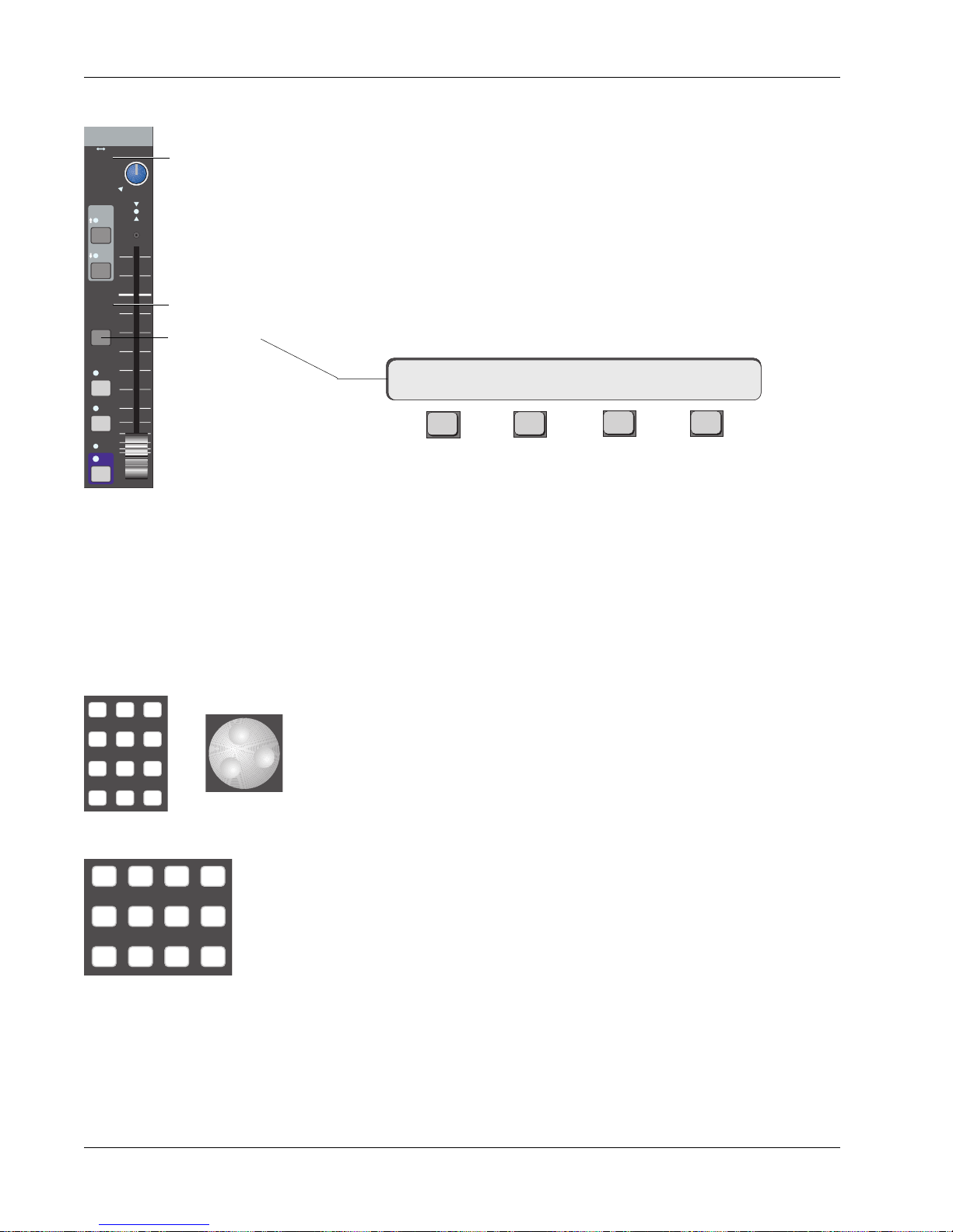
Section 4: Tutorial
Channel Blocks
Input
M1 M2
L1 L2
L3 L4
EQ•Dyn
12L
BUS
DIR
ST1
ST2
PAN BAL
ovld
R
Source Indicators
Assign Indicators
Fader Block
PFL
AFL
Grp
ON
Key
Routing
Parameters
The channel strip is organized into 7 channel blocks. Each block has its associated attention key located within the block. These are the Channel block,
Universal Input blocks (M1 & M2), Aux Send blocks (A/B & C/D), Upper Fader
block, and Lower Fader block. Take a moment to identify the individual blocks
of a channel strip on your console using the diagram on page 1-6.
When you press a block attention key, you can control that block via the
Master Control Panel and the DSC. You will then be able to configure the
signal path of that block directly from the DSC.
Press the lower fader block attention key on channel 16. You will notice that
the SmartDisplay on the Master Control Panel shows the following menu:
16LF-> SRC MODE ASGN
F3F1 F2 F4
“16LF” means that the Master Control Panel now controls channel 16’s lower
fader block. The arrow indicates that the routing for that block is described in
the menus to the right. We have to select the input source (SRC) for the fader,
the mode (MODE) of the fader, and the output assignment (ASGN) for the
fader’s signal. Source and assign selection can be done directly from the DSC
Dedicated Keys section. Sources and assignments are indicated on every block
by hidden-til-lit displays for easy reference.
789
456
123
0 Enter Del
M1 M2 DIR All
L1 L2 ST1 All
L3 L4 ST2 All
or
aux
upper
lower
DSC Source/Assign
Dedicated Keys
Mode
Source
Assign
Modes are used to select how signals are routed and combined through the
two DCAs of each fader or aux send block. Mode selections can be selected
directly from the DSC Numeric keypad or by scrolling through modes using the
SpinKnob. Until you gain familiarity with the options, press SmartDisplay key
[F3] (MODE) and use the SpinKnob to find the mode you need. If you are
familiar with the modes, you can enter the corresponding mode number, then
press the DSC [Enter] key. A complete listing of available modes to each
block can be found in the Appendix section.
Source selections can be any of the console channel strip’s 6 inputs. They are
M1, M2, L1, L2, L3, and L4. M1 and M2 are commonly thought of as microphone preamplifiers, but are actually universal input amplifiers (U.I.A.s) that
accept a wide range of levels and impedances. Each of these inputs is
equipped with phase reverse, high-pass filter, and phantom power. The DCA
for M1 can be used for the Combiner. L1 - L4 are simply non-variable, line-level
amplifiers. Both M2 and L4 inputs have the option of bus/tape switching.
Assignment selections are ST1, ST2, Multitrack group buses (24 from upper
fader only, or 12 from upper and lower faders depending on Audio Tower
jumper configuration - see technical manual for details), Direct Outputs (Dirs 1
& 2), and Aux buses 1 - 8 (from the aux blocks only).
4 - 4 Euphonix CS3000/2000 Operation Manual
Page 75
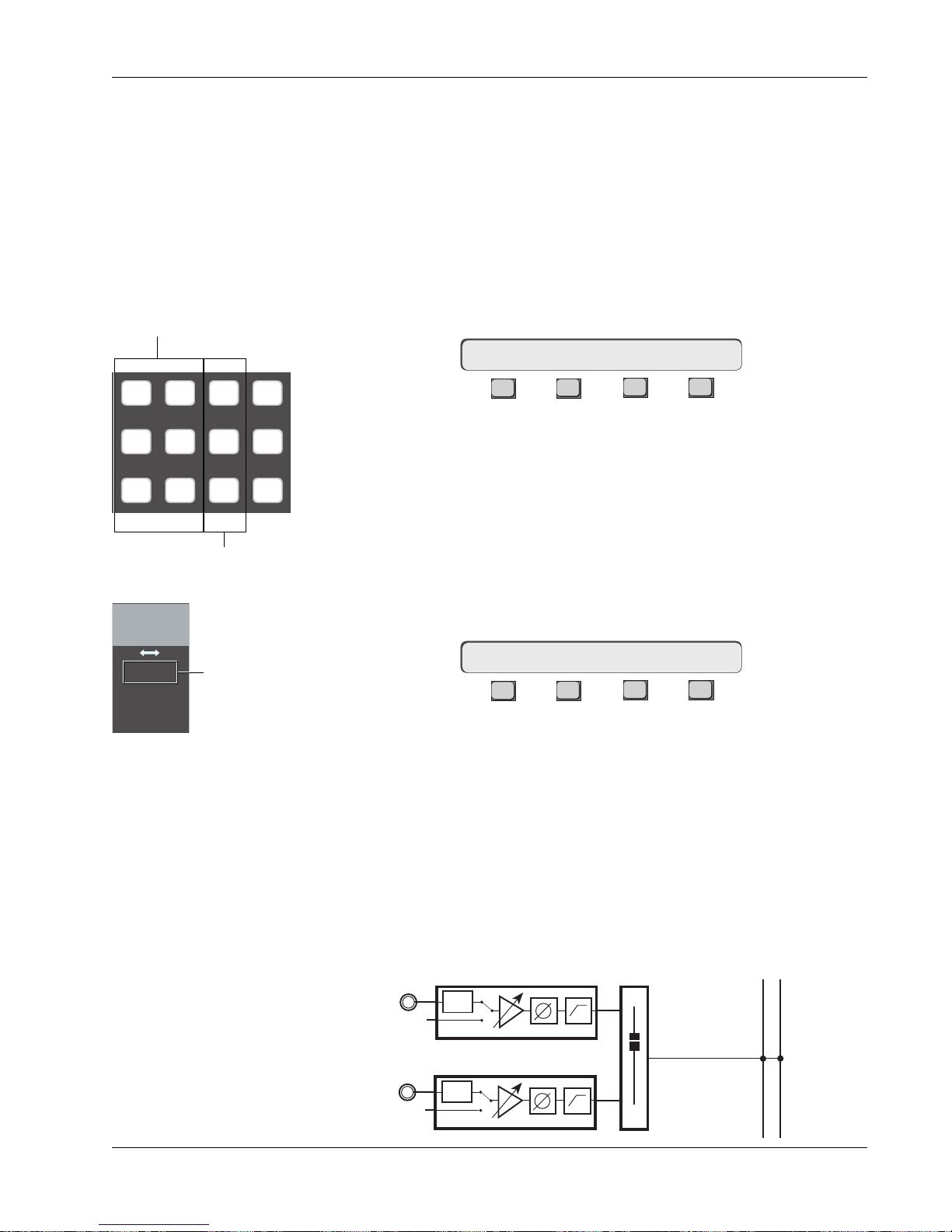
Section 4: Tutorial
Exercise 1
Stereo Source/
Stereo Fader/
Stereo Bus/
Monitor
Source
Source Dedicated keys
M1 M2 DIR All
L1 L2 ST1 All
L3 L4 ST2 All
Assign Dedicated keys
aux
upper
lower
In this exercise we will construct a stereo signal path to route a stereo source
through the console and out to the monitors.
Begin this exercise from a “Default” (or zeroed) console, and create a new title
in which to store your Tutorial work. Patch your sound source into the M1 &
M2 inputs of a channel. We will use channel 16 for this example. A compact
disc makes a good sound source because it’s usually 45 minutes of uninterrupted signal. Start playing the sound source you are going to use now.
Press channel 16’s lower fader block key. Notice that the menu in the SmartDisplay has changed to this:
16LF–> SRC MODE ASGN
F3F1 F2 F4
This means that you now have control of channel 16’s lower fader from the
DSC. Select the source by pressing the [M1] & [M2] Dedicated keys. Notice
that when you press these keys, the M1 & M2 Source LEDs light in channel
16’s lower fader block. If you press [M1] again, notice that it toggles the M1
source off. In this case, only the M2 input is feeding the fader. Press [M1]
again to re-select it, checking the final routing by looking at the Source display
next to the pan/bal control of the fader block as seen in the diagram to the
left. Select [L1] through [L4] in the same way. Selections will appear in the
SmartDisplay:
Input
M1 M2
L1 L2
L3 L4
M1 & M2 only
are sourced from
lower fader
Assign
SRC–> M1 M2 L1 L2 L3 L4
F3F1 F2 F4
While in the SRC menu, pressing the DSC [Clr] key clears all input selections.
Clear the selections and select only M1 & M2.
Next we will select an assignment to send the fader output to a desired
destination. In our example we will assign to the ST1 bus. Press the DSC [ST1]
Dedicated key. You will now see that ST1 Assign LED lights in 16’s lower fader
block. Try deselecting ST1 by pressing the [ST1] Dedicated key again, and
selecting [ST2] as the destination. ST2 is a completely separate stereo bus
with its own master fader, insert and patch points. Re-select only ST1.
The signal path we have set up now looks like this:
STEREO 1 BUS
L R
M1
PWR
Euphonix CS3000/2000 Operation Manual 4 - 5
M2
PWR
LF
Page 76

Section 4: Tutorial
Mode
SIDE NOTE:
The default fader
mode is mono.
Let’s select a MODE for the lower fader block. This can be done directly from
the Numeric keypad or by using the SpinKnob. If you are familiar with the
modes by number (see Appendix A-3), enter the mode number and then press
the DSC [Enter] key. In our example we will use Mode 7-Stereo. Press 7 (you
will see 7 blinking in the SmartDisplay) then press the DSC [Enter] key. The
other way to select modes is to use the SpinKnob. First press [F3] to access
the Mode menu:
16LF–> SRC MODE ASGN
F3F1 F2 F4
16LF–> MODE 7:Stereo
F3F1 F2 F4
Using the SpinKnob, scroll through the modes until you see Mode 7:Stereo.
There is no need to press Enter when using the SpinKnob, just [ESC]ape back
up the menu tree.
The Bal LED below the fader’s Pan/Bal control will light, indicating that you
have now placed a balance control in the signal path. The signal flow diagram
is now:
Meters
STEREO 1 BUS
L R
M1
M2
PWR
BAL
PWR
LF
Modes are a very important and powerful part of the routing structure of the
console. You should experiment with modes and be familiar with all of them.
See Appendices 3 and 4.
If you began the Tutorial with a “Default” (zeroed) console (all faders, controls
down and routing unassigned), then the meters will be in their OFF mode. We
will assume this is the case and set up the meters now.
We will show how to set the meter modes globally for all channel I/O meters
and then for individual channels via the SmartDisplay Meter menus. We will
also set the meters for the Master Module.
4 - 6 Euphonix CS3000/2000 Operation Manual
Page 77
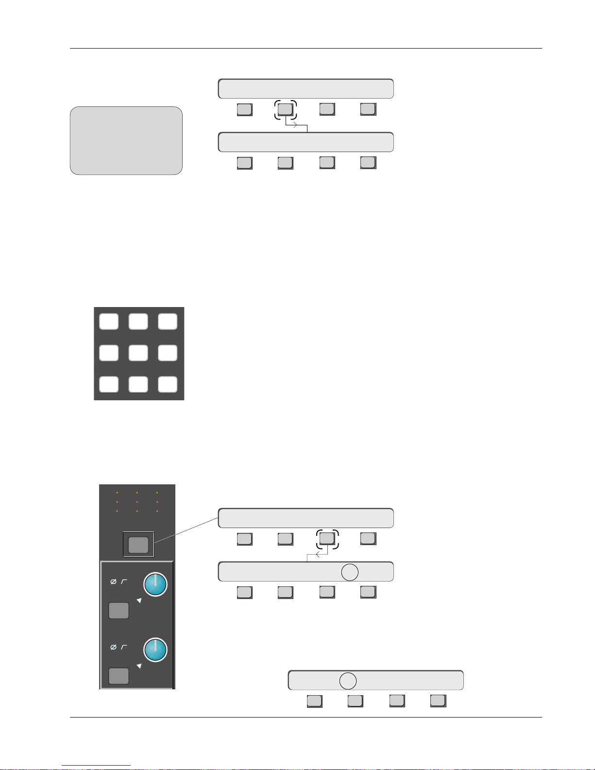
Section 4: Tutorial
B
Global Channel (I/O)
Meter Mode Selection
SIDE NOTE:
Assigning meter modes
globally by using the DSC
Mtrs key, always overrides
and changes any individual
channel meter assignments.
Metering Mode Presets
789
456
123
For the global setup, press the DSC [Mtrs] key, then [F2] (I/O):
Mode I/O Master
F3F1 F2 F4
**CH->Aud:OFF Aud->OFF
F3F1 F2 F4
Meter Menu
Meter Config Menu
The two asterisks (**) preceding the channel designator indicate that we are
affecting all I/O meters simultaneously.
Metering presets allow you to easily configure meter pairs. Pressing any of the
DSC Numeric keypad keys recalls these Meter selection presets. Following is
a list of the available presets:
KEY LEFT METER: RIGHT METER:
E Rev F Rev E Rev F Rev
[0] — Aud:OFF Aud:OFF Aud:OFF Aud:OFF
[1] — Aud:M1 Aud:M1 Aud:M2 Aud:M2
[2] — Aud:L3 Aud:L1 Aud:L4 Aud:L2
[3] — Aud:MT Aud:L3 Aud:L4 Aud:L4
[4] — Aud:LFL Aud:CMB Aud:LFR Aud:MT
[5] — Aud:UFL Aud:MT Aud:UFR Aud:CMB
[6] — Lvl:UF Aud:LFL Lvl:LF Aud:LFR
[7] — Lvl:M1 Aud:UFL Lvl:M2 Aud:UFR
[8] — - - - Lvl:UF - - - Lvl:LF
[9] — - - - Lvl:M1 - - - Lvl:M2
Individual Channel (I/O)
Meter Mode Selection
Pressing the DSC [*ST] key while the Meter Config menu is visible, switches
you into individual meter config mode. There is another way to set meter
modes for individual channels. Press a channel’s attention key located just
M
L
L
M1
12
12
34
ovld
M
L
L
12
12
34
M
12
L
12
L
34
Out 1 Out 2 Out 3
Pwr
Pad
under the I/O channel’s meter array, then press [F3] (METER):
1CH-> OUTs METER Route
F3F1 F2 F4
1CH->Aud:OFF Aud->OFF
F3F1 F2 F4
Starting with unconfigured meters, attention is initially directed to the right
Pwr
M2
channel meter as indicated by the arrow between Aud and OFF shown above.
Press [F2] to direct attention to the left meter:
Pad
ovld
1CH->Aud->OFF Aud:OFF
F3F1 F2 F4
Euphonix CS3000/2000 Operation Manual 4 - 7
Page 78
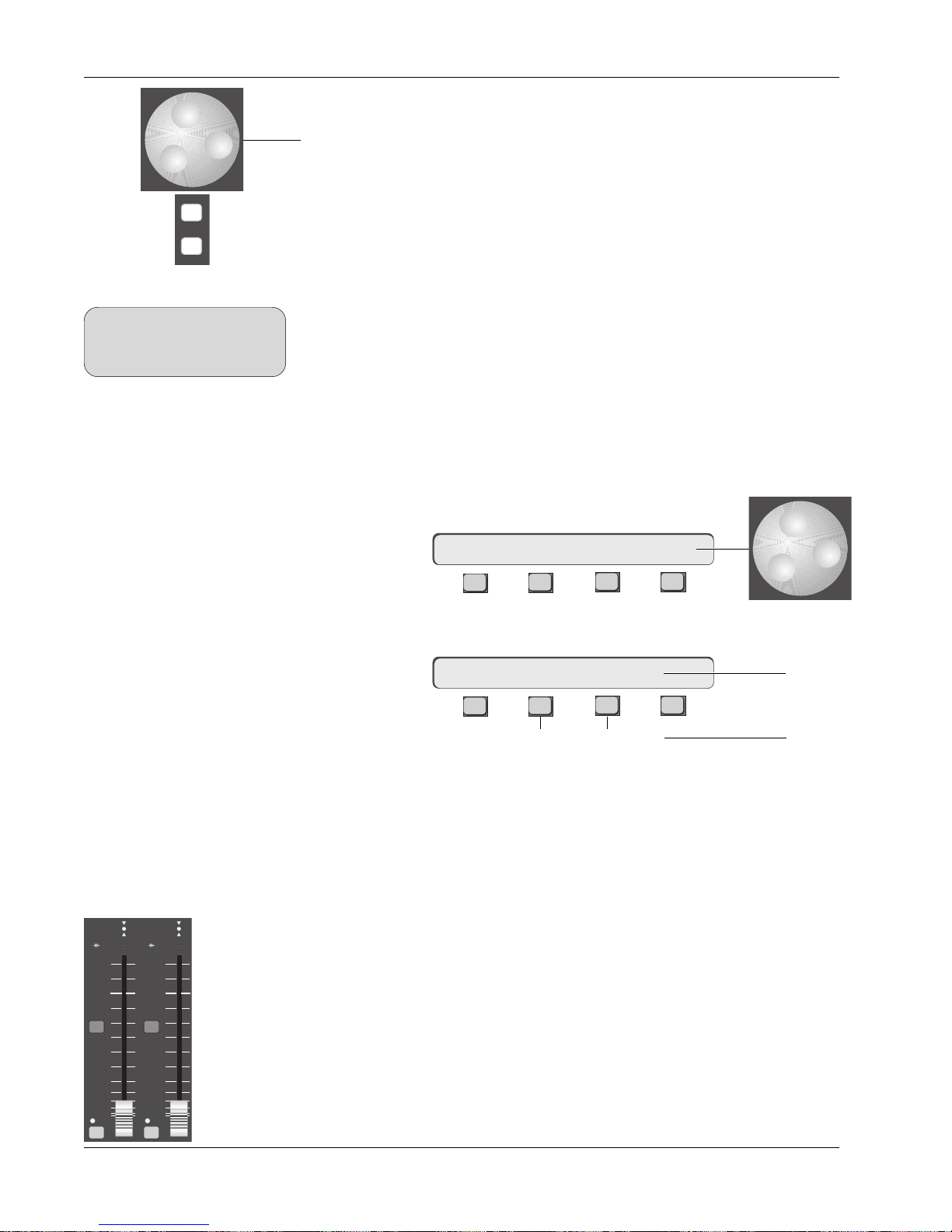
Section 4: Tutorial
Pressing [F2] again toggles the meter mode between Aud (Audio signal) and
Lvl (DCA level). This menu structure allows each meter’s source to be assigned
using the SpinKnob or [+]/[–] keys.
The following list details available selections:
+
Bus
DIR
SIDE NOTE:
Any combination of sources you
cannot monitor directly can be
monitored using the Combiner.
Master Module Meter
Selection
LEFT METER:
Aud: M1, L1*, L3, CMB*, MT, LFL, UFL, OFF
Lvl: UF, UP, A, C, M1, OFF, LF, LP, B, D, M2
RIGHT METER:
Aud: M2, L2*, L4, MT*, CMB*, LFR, UFR, OFF
Lvl: LF, LP, B, D, M2, OFF, UF, UP, A, C, M1
An asterisk (*) indicates that choice is available only for F Rev ch. hardware.
Now we will set the Main meters in the master section. [Esc]ape once to get
to the Meter menu, then press [F3] to select the Master Meter options. There
are 10 master metering modes available. These modes are explained in detail
in Appendix 7. Choose Mode 2 using the SpinKnob. This mode allows you to
meter Aux buses 1-4, ST1, and ST2 signal levels:
mME–>DISP 2: A1-A4 STs
F3F1 F2 F4
From the Meter menu, press [F1] (Mode):
+18 to -42dB
**ME= RMS 18-42
range
ovld ovld
BAL BAL
ST1 ST2
ON ON
Stereo
Output
Faders
F3F1 F2 F4
PEAK 6-33
+6 to -33dB
range
[F2] selects different meter characteristics. [Clr] will set the meters to the
default settings shown above. [F3] selects the range of the meter. The 0 VU
point is the same for both ranges, only the high and low limits change. The
mode selection is global and affects both channel and master meters.
The next step in completing the signal path is to turn on channel 16 and bring
up channel 16’s lower fader. You’ll find the fader ON button, a.k.a. “mute”, at
the bottom left of the fader block. A green LED above the ON button shows
that the fader is on. Bring the fader up to 8 on the scale. This represents 0 VU
or “unity gain”. Press the ST1 [ON] button and bring the master fader to the 8
(unity gain) mark. Assuming you have successfully setup the Master meters
and your audio source is playing, you should now see the audio levels on ST1
output.
4 - 8 Euphonix CS3000/2000 Operation Manual
Page 79
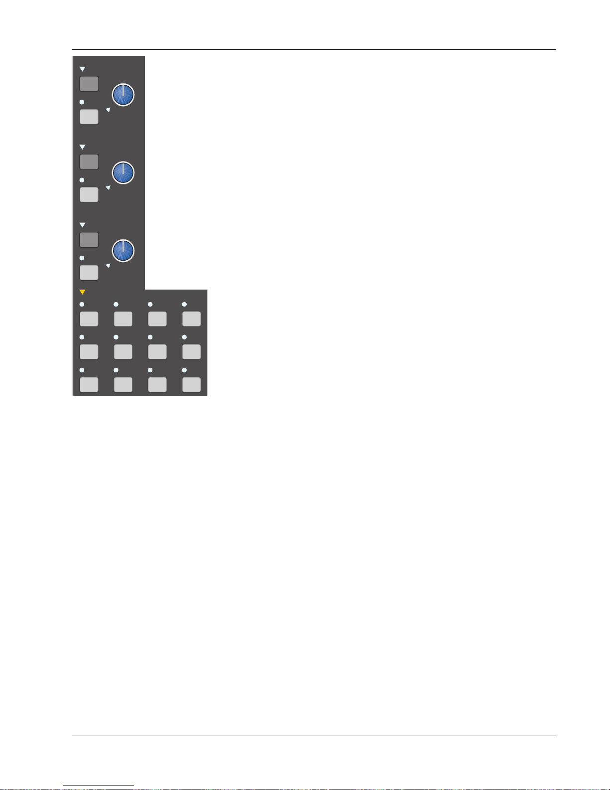
Section 4: Tutorial
S
SET
A monitor
Monitor
Source
DIM
SET
B monitor
DIM
SET
C monitor
DIM
monitor SET
A1•2 A3•4 A5•6 A7•8
Ext 1 Ext 2 ST1 ST2
Selection
Kill
SOLO
A
B
C
Active
Solo
Ext—
C pre
D monitor
The CS3000/2000 is equipped with 3 monitor speaker outputs labelled A, B &
ST1
C. Each monitor section has its own Level control, DIM, and SET keys. We will
ST2
assume there are amplified speakers connected to the “A” Output. We will
BU
listen to ST1 through Monitor A. First, turn Monitor A’s level control down
(fully counter-clockwise). Next, press A’s [SET] key and the Monitor Set area,
located below the monitor controls, will reflect A’s output selections. Press the
[ST1] key in the Monitor Set area. Now slowly turn Mon A’s level control up to
hear the audio. The 4 lower keys in this area determine the mode of the
selected monitor output; either (Left or Left to both), (Right or Right to both),
Stereo or Mono. Try toggling between them now while the sound source is
playing.
It is useful to note that the selections in the Monitor Set area are additive and
not intercancelling. This means that you can listen to both ST1 and ST2 out of
Monitor A. In fact, you could listen to a sum of all 8 monitor sources.
A1-A8 are the Aux buses and Ext1, Ext2 are external patchable inputs for tape
returns, reverse talkback, etc. Each EXT input is actually made up of three
stereo inputs which can be summed together. So on the Master patchbay
there are three stereo inputs for EXT1 labelled EXT1(A), EXT1(B) and EXT1(C).
There are three similarly labelled inputs to EXT2 (see page 5-12).
Left Right Stereo Mono
Save That Console
You will also notice that a menu comes up in the SmartDisplay when you press
the [SET] key. This menu allows you some additional options for each monitor
output. These options are detailed later in this section.
With any computer-based system, regular saving of work is essential. The
same is true with your Euphonix System. You may need to refer back to
Section 3 for details on snapshot store and recall procedures. Storing a
snapshot can be done from the DSC’s Assignable Keys section. Press the
[SnapShot] mode key, then the [Store] key, then name the snapshot if you
wish and press the Assignable Key for the snapshot location you wish to use.
For this example, try using snapshot location #10.
Remember that the red indicator next to the snapshot number on the screen
indicates it is not stored to disk yet. It will not be stored to disk until the next
time you save your title. After the title is saved, the indicator will turn green.
This concludes Exercise 1.
Euphonix CS3000/2000 Operation Manual 4 - 9
Page 80

Section 4: Tutorial
Universal Input
Amplifiers (UIAs)
M1 & M2
M1
Pwr
Pad
ovld
MixOnPass
Setup Snap System Grps
F1 F2 F3 F4
789
456
123
0 Enter Del
low gain
med gain
Rec
high gain
Pass
Ctrl
+
Bus
DIR
*
ST
Grps Mtrs
Stereo Link
Clr Esc
Let’s return to the channel and adjust the input levels to assure a reasonable
gain structure. To do this we need to look in more detail at the Universal
Inputs (M1 & M2). Press M1’s block key to access its control parameters.
U.I.A. Menu
16M1–> low/ 0.0dB Cnfg
F3F1 F2 F4
Notice that the actual gain level is shown in dB, and that the level in the
display changes along with the signal level of the left channel as you rotate
the gain pot. The input amps can toggle between 3 gain ranges by pressing
keys 1, 2, or 3 on the numeric keypad or by pressing the DSC [+]/[–] keys. The
ranges are:
1/Low 0.0dB to +24.0dB (lights PAD LED in M1 or M2 block)
2/Med +20.0dB to +44.0dB (PAD LED off)
3/High +40.0dB to +64.0dB (PAD LED off)
Set the gain now by turning the M1 gain pot until the null indicator goes out,
and then adjust the level while watching the meters (about +12dB for a CD
player). If the gain is set too high, the clipping indicator will light in the
respective input block. Clip Indicator threshold adjustment is covered later in
this section.
When using the two U.I.A.s as a stereo source (as we are), it may be preferable to lock the two gain controls together to form a single stereo input gain
control. To do this, press the M1 or M2 block key. Press the [*ST] key on the
Master Control Panel. This will lock the two controls, disable the M1 level
control, and allow the M2 level control to be the master. You should see an
asterisk (*) in the SmartDisplay above F2 and the null indicator on the M1
control becomes permanently lit, indicating that the M1 control is disabled.
Stereo link asterisk above F2
They can be unlinked simply by pressing the [*ST] button again when in M1 or
M2 input menus. The * indication in the display goes away to show that the
SIDE NOTE:
Bus/Tape switching
input blocks are now separately controlled.
The M2 input can monitor the channel’s bus signal. Press M2’s block attention
key, then press [F2] below the SmartDisplay. If the multitrack return is
Multitrack Return
M2
PWR
normalled into M2 then [F2] acts as a bus/tape switch.
From Bus Summing Amp
4 - 10 Euphonix CS3000/2000 Operation Manual
16M1–> *low/ 4.0dB Cnfg
F3F1 F2 F4
16M2–> Bus/ 4.0dB Cnfg
F3F1 F2 F4
Acts as bus/tape switch
Page 81
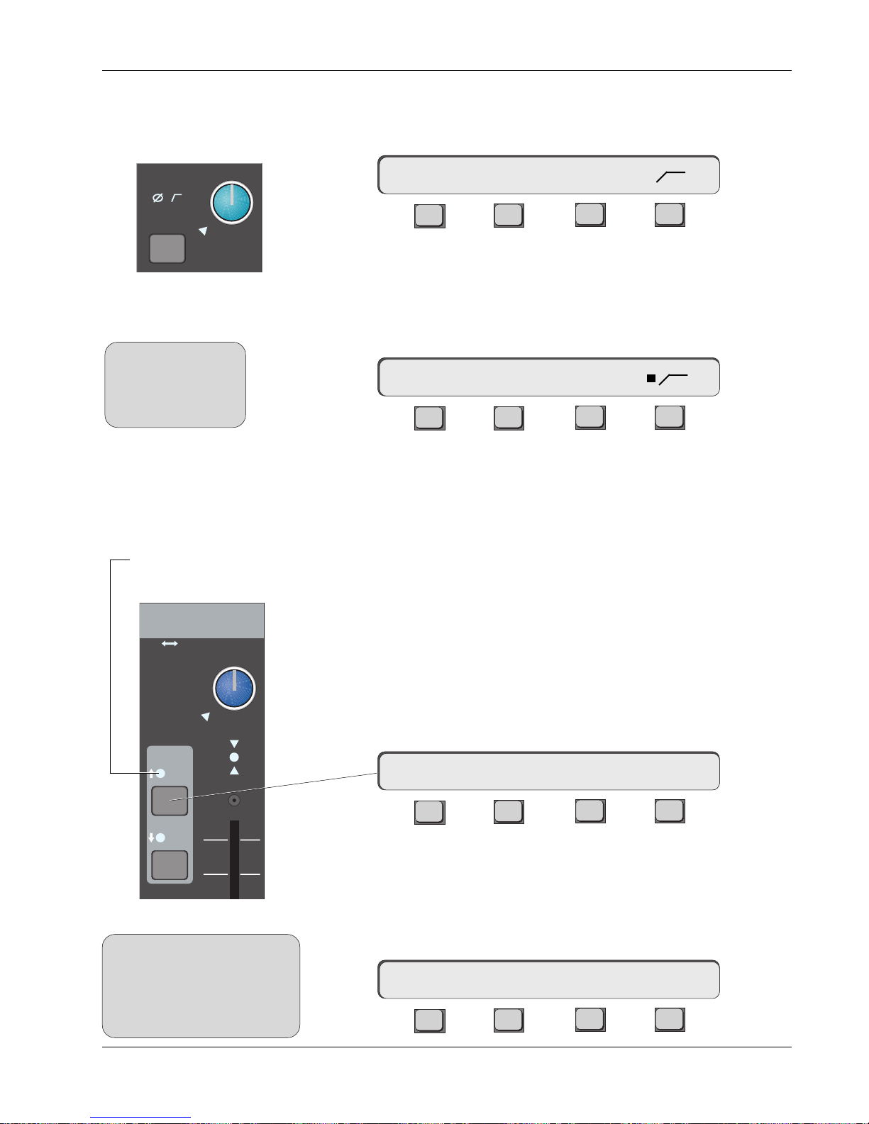
Section 4: Tutorial
Phase Reverse, Filter,
Phantom Power
M1
Pwr
Pad
ovld
SIDE NOTE:
Cnfg assignments do
not carry over between
stereo linked U.I.A.
inputs.
Each U.I.A. has phase reverse, high-pass filter (3dB down at 100Hz), and
phantom power control. Press the M1 block key to access the U.I.A. menu then
press [F4] (Cnfg) to access the U.I.A. Configure menu:
16M1–> PWR Ø
F3F1 F2 F4
[F2], [F3], & [F4] toggle the options on and off. If selected, the appropriate
indicator will light in the M1 block and a square indicator appears next to the
selected item in the SmartDisplay menu.
Press [F4] to turn on the filter and observe the SmartDisplay menu:
16M1–> PWR Ø
F3F1 F2 F4
Also observe the filter icon light in the M1 block of the selected channel. Press
[F4] again to toggle the filter off.
Equalizers
EQ LED illuminates when
assigned to an input
Input
M1 M2
L1 L2
L3 L4
PAN BAL
EQ•Dyn
SIDE NOTE:
The EQ1 and EQ2 keys are located
in the lower fader block for
convenience. They are not
necessarily part of the lower fader
signal path.
ovld
12L
R
Each channel strip is equipped with two 4-band equalizers. Each EQ can be
assigned to any one of the 6 input sources. When assigned to the same source
“cascaded”, the EQs form a 8-band parametric EQ. Stereo linked, the two EQs
track each other, which is to say they’re both equal masters and can control
each other.
Let’s set up a stereo EQ in the lower fader signal path. With the DSC EQ key
lit, press the EQ•Dyn 1 attention key, located in channel 16’s lower fader
block. You will see that the SmartDisplay shows channel 16’s EQ1 parameters,
and the DSC screen now displays the EQ frequency response curve.
16E1–> lmG 0.0dB –>>-
F3F1 F2 F4
The EQ is not yet in circuit, as shown by the open insert icon (–> >-) above F4.
In this case we want EQ1 to be inserted into the signal path just after M1
input. To do this, go to the DSC Source Dedicated Keys and press M1. The EQ1
indicator comes on in the channel fader block showing that the EQ is now in
circuit. Also the source M1 is shown in the DSC screen and SmartDisplay:
16E1–> lmG 0.0dB –>M1>-
F3F1 F2 F4
Euphonix CS3000/2000 Operation Manual 4 - 11
Page 82

Section 4: Tutorial
Select EQ2’s source in a similar manner by pressing the EQ•Dyn 2 attention
key then the [M2] Source Dedicated Key. As before, this routing selection is
also seen in the far right of the SmartDisplay within the insert icon.
16E2–> lmG 0.0dB –>M2>-
F3F1 F2 F4
The EQ may be switched in and out of circuit by pressing [F4] or by pressing
the rightmost of the 4 Function keys just below the Assignable Rotary Control
Set. (See the Introduction Section.)
Stereo Linking EQs
Indicates stereo link
This is our signal path now:
M1
M2
PWR
Stereo Link
PWR
EQ1
4 Band EQ
4 Band EQ
EQ2
LF
BAL
STEREO 1 BUS
L R
As mentioned earlier, the two EQs may be linked together to form a stereo
pair. When in the EQ menu, press the [*ST] key on the Master Control Panel.
When stereo linked, both EQs are adjusted in tandem to give you a true stereo
4-band parametric. At any time you can unlink the two EQs by pressing the
[*ST] key again. When the two EQs are working in stereo, the SmartDisplay
indicates this with a “*”.
16E2–> *lmG 0.0dB –>M2>-
F3F1 F2 F4
SIDE NOTE:
The Page 1 and Page 2
buttons on the DSC both
illuminate to indicate
when a pair of EQs is
stereo linked.
the EQ title bar.
When you stereo link EQs by pressing the [*ST] key, all of the parameters of
the selected EQ are copied into the other EQ. For example, if EQ1 is selected
when you press the [*ST] key, EQ1’s curve is copied into EQ2. Likewise, if EQ2
is selected when you press the [*ST] key, EQ2’s curve is copied into EQ1.
Signal path after
stereo linking EQs
In addition, the screen display indicates “Stereo EQ 1” instead of “EQ 1” on
M2
4 - 12 Euphonix CS3000/2000 Operation Manual
M1
PWR
PWR
Stereo Links
EQ1
4 Band EQ
4 Band EQ
EQ2
LF
BAL
STEREO 1 BUS
L R
Page 83

Section 4: Tutorial
Adjusting EQ with the
DSC
SIDE NOTE:
Once the EQ is accessed, the Assignable Rotary Control Set at the top of the
DSC is mapped to the EQ. The control assignments are shown on the screen
display along with the actual EQ graph:
Controls mapped to
DSC Rotary Controls
These switches
are mapped to the
DSC Function keys
just below the
Rotary Control Set.
Refer to the Introduction section for more information on the mapping of these
controls. As soon as an EQ attention key is pressed, that EQ curve is automatically drawn on the screen display. As you make adjustments from the DSC
Rotary Controls, the EQ curve is updated in real-time on the screen. This gives
you a clear visual representation of the EQ response.
Default EQ Values
The EQ curve can be flattened either by pressing the assignable function key
corresponding to the Clear function in the DSC screen or the [Clr] key when in
the EQ SmartDisplay menu. This sets default values for frequency and Q as
well as setting all gains to 0. It is like centering the Gain, Q, and Frequency
knobs on a conventional console EQ. The list below shows the default values:
Band Frequency Note Q
High 10.5kHz E9 n/a
High Mid 2.64kHz E7 0.51
Lower Mid 330Hz E4 0.51
Low 82.4Hz E2 n/a
EQ 1 (M1)
15
12
9
6
3
0
3
6
9
12
15
21 41 82 165 330 659 1.3K 2.6K 5.3K 11K 21K
15
12
9
6
Default values with
3
0
no routing selected
3
6
9
12
15
Euphonix CS3000/2000 Operation Manual 4 - 13
Page 84

Section 4: Tutorial
EQ Screen Display
15
12
9
6
3
0
Info Bar
Low Range
(Red)
EQ(1) or EQ(2)
EQ Routing (bypassed)
EQ 1 (M1)
Lower Mid-Range
(Yellow)
High Mid-Range
(Green)
High Range
(Blue)
15
12
9
6
3
0
3
6
9
12
15
21 41 82 165 330 659 1.3K 2.6K 5.3K 11K 21K
Gain/Attenuation in dB Frequency in Hz
Frequency Range
The frequency range of each of the 4 bands is shown on the screen. The high
mid and the low mid have extended ranges to allow them to overlap with the
high and low bands, thus making two bands available in the high and low
regions.
3
6
9
12
15
EQ Routing Source
4 - 14 Euphonix CS3000/2000 Operation Manual
When you select a source for the EQ (M1, M2, L1, L2, L3, L4), that source
appears in the EQ graph info bar. If the source is selected but the EQ is bypassed (“out”), the source appears in parentheses as seen in the diagram
above.
Page 85

Section 4: Tutorial
EQ Curves
As the EQ parameters are adjusted, the graph instantly displays an accurate
representation of the EQ response curve. The illustration below shows the low
gain increased to +12dB at 82.4Hz. Note that +12dB refers to the
of the EQ boost (the horizontal asymptote to the curve) and not to the amount
of boost at the actual filter cut-off frequency. This is typical of an analog EQ.
Adjusting Low Gain
+12dB @ 82.4Hz
Changing the low frequency to 165Hz will change the curve as seen below:
Adjusting Low Gain
+12dB @ 165Hz
EQ 1 M1
15
12
9
6
3
0
3
6
9
12
15
21 41 82 165 330 659 1.3K 2.6K 5.3K 11K 21K
EQ 1 M1
15
12
9
6
3
0
3
6
9
12
15
21 41 82 165 330 659 1.3K 2.6K 5.3K 11K 21K
infinite limit
15
12
9
6
3
0
3
6
9
12
15
15
12
9
6
3
0
3
6
9
12
15
Adjusting Upper-Mid
Gain +12dB @ 2.64kHz
Euphonix CS3000/2000 Operation Manual 4 - 15
Press the DSC [Clr] key to clear the EQ and boost the upper-mid gain by 12dB
@2.64kHz. With the Q value at 0.51, the EQ graph will look like this:
EQ 1 M1
15
12
9
6
3
0
3
6
9
12
15
21 41 82 165 330 659 1.3K 2.6K 5.3K 11K 21K
15
12
9
6
3
0
3
6
9
12
15
The SmartDisplay shows the parameter values changing in real time as you
adjust the EQ.
Page 86

Section 4: Tutorial
Musical Note Value
Display
Screen display
EQ screen
The EQ can be switched from Frequency to Note mode. In Note mode, the
horizontal scale on the graph as well as the SmartDisplay frequency values
will show musical notes on a 12 note, A440 scale as the controls are adjusted.
Note mode can be entered while in EQ mode by pressing the Special Function
key corresponding to the Notes function in the DSC screen (see diagram
below), or by pressing the SmartDisplay [F3] key:
Q Range
[F1] clears EQ and
resets to default
Special Function keys
of Assignable Rotary
Control Set
The range of the Q on the mid bands is variable from 0.32 at its broadest to
11.6 at its narrowest. The default Q value is 0.51.
dt
i
Pg 1 Pg 2 Pg 3 Pg 4
dt
i
DynEQ
Aux Pan
dt
i
Assign
Bus
Master
i
SmartDisplay in Musical Note mode
16E1–> lmF E7 –>M1>-
F3F1 F2 F4
[F3] changes
to Note mode
dt
List
Chan
4 - 16 Euphonix CS3000/2000 Operation Manual
Page 87

Section 4: Tutorial
Adjusting the EQ
Using Keypad
The EQ can be adjusted using the numeric keypad and the SpinKnob on the
DSC Master Control Panel. The 12 keys that make up the numeric keypad
select the parameter that the SpinKnob adjusts:
Attenuation/Gain
Frequency/Note
Key not used
Q
High
High Mid
Lower Mid
Low
789
456
123
0 Enter Del
+
Bus
-
*
DIR
ST
Clr Esc
Recalls default value for
selected parameter
Copying EQ values
• Actual EQ parameter values are shown in the SmartDisplay as well as on
the screen display.
• Pressing the DSC [Del]ete key clears the selected band to its default
values.
• To add low boost, press the [0] key and turn the SpinKnob clockwise,
watching the screen display to see the curve as it adjusts. You can also
nudge the values up and down using the [+] & [–] keys.
• To adjust the high-mid gain, press the [4] key and turn the SpinKnob.
• To adjust the high-mid center frequency, press the [5] key and turn the
SpinKnob.
• To adjust the high-mid Q, press the [6] key and turn the SpinKnob.
• Since there is no Q control for the high and low bands, the 9 key has no
effect.
EQ parameters can be copied from one EQ to another. Once you’ve adjusted an
EQ to your liking, press [F1] in that EQ’s SmartDisplay menu. You will see
question marks above F1 asking where to copy the EQ values. Press any EQ
attention key and the whole EQ curve will be copied into that EQ.
????<–16EQ1 Gs/Fs/Qs
Euphonix CS3000/2000 Operation Manual 4 - 17
F3F1 F2 F4
The SmartDisplay is showing you that the Gains, the Frequencies and the Qs
will be copied across.
Page 88

Section 4: Tutorial
Cascading 2 EQs to
Produce an 8-Band EQ
SIDE NOTE:
Current software does not
allow the composite EQ curve
to be shown on one graph.
You must view the EQ1 and
EQ2 curves separately.
M1
Up to now we have only covered placing one EQ in each signal path (i.e., EQ1
to M1 and EQ2 to M2). It is possible for both EQs to be assigned to a single
source. Select M1 as the source for both EQ1 and EQ2. In this case EQ2
follows EQ1 and they are in cascade mode. Now you have an 8-band parametric EQ.
The diagram below shows the signal path with two EQs in cascade mode:
STEREO 1 BUS
EQ2EQ1
PWR
4 Band EQ 4 Band EQ
ST* In/Out Switching
Link Only
LF
PAN
At this point you should be listening to the audio source through the console.
Save your work to a SnapShot (either SnapShot #10 or another SnapShot
location if you wish). Review the exercise a couple of times and try making
slight variations to the EQ, pan, or fader levels and save them to SnapShots.
Then, while listening to the audio source, recall different SnapShots and listen
to the effect of the variations you’ve saved.
L R
Insert Points
Unlike conventional consoles which provide 1 fixed insert point, the CS3000/
2000 allows you to build insert points into the signal path when and where
they are required. Each channel can have up to 3 insert points. This could
provide a pair of insert points for a stereo fader and the third insert point could
be used for a mono fader.
Each channel has 4 line inputs (L1, L2, L3, L4) and 3 pre-fader line outputs
(Out1, Out2, Out3). Line 4 or Mic 2 inputs are usually used as multitrack
returns because of their bus/tape switching capabilities. This leaves 3 in/out
pairs to build the 3 insert points, and Out1/L1, Out2/L2, and Out3/L3 are
typically used as these insert send/return pairs.
4 - 18 Euphonix CS3000/2000 Operation Manual
Page 89
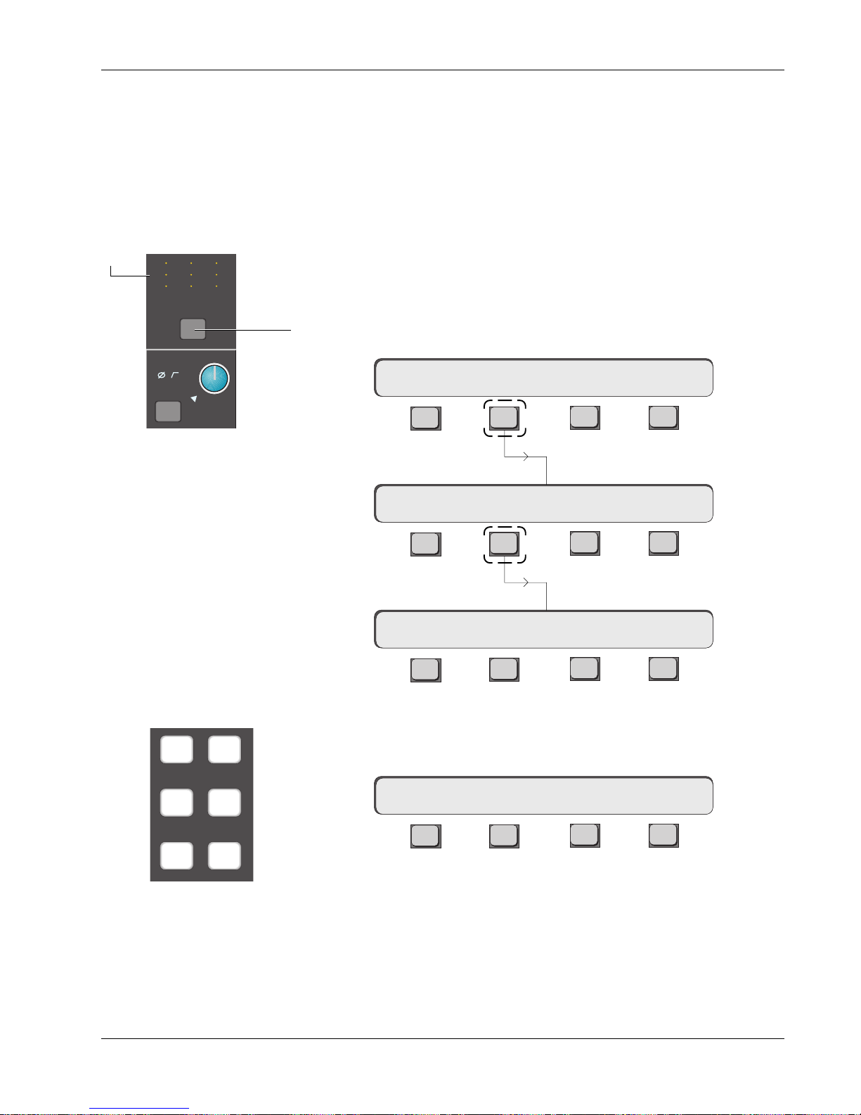
Section 4: Tutorial
B
Exercise 2
Stereo Inserts
into Audio Path
Source indicators illuminate
as Out 1, 2, & 3 sources are
selected.
M
12
L
12
L
34
Out 1 Out 2 Out 3
Pwr
Pad
M
L
L
12
12
34
M1
M
L
L
ovld
12
12
34
In this exercise we will construct a post-EQ stereo insert point inserted into
the signal path. First we will send M1 & M2 to Out1 & Out2 respectively. Outs
1 & 2 appear at the patchbay and are now effectively the insert sends. The
fader’s source will be Line Inputs 1 & 2 which are now effectively the insert
returns. This is shown in the signal flow diagrams on the next page.
Press channel 16’s lower fader block key. Now deselect M1 and M2 as the
fader source and select L1 and L2 instead. The fader is now being fed from
Line Inputs 1 & 2.
The CD source, still coming in on channel 16’s M1 & M2 inputs (from Exercise
1), is no longer routed anywhere. We will send it to Outs 1 & 2.
Press the channel block attention key at the top of channel 16.
16CH–> OUTs METER Route
Press [F2] to select
F3F1 F2 F4
the Output menu:
16CH–> OUT1 OUT2 OUT3
Press [F2] to select the Source menu for Output 1:
F3F1 F2 F4
16CH–> OUT1 ?
F3F1 F2 F4
Select [M1] using the DSC Dedicated Keys. M1 is now routed to Output 1. This
is indicated in the SmartDisplay and in the Out1 display at the head of the
M1 M2
L1 L2
L3 L4
channel.
16CH–> OUT1 M1
F3F1 F2 F4
Press [Esc] once to return to the Output menu and then F3 to select the Source
Dedicated Source
menu for Output 2. Select [M2] as the source for Output 2.
Assign keys
Euphonix CS3000/2000 Operation Manual 4 - 19
Page 90
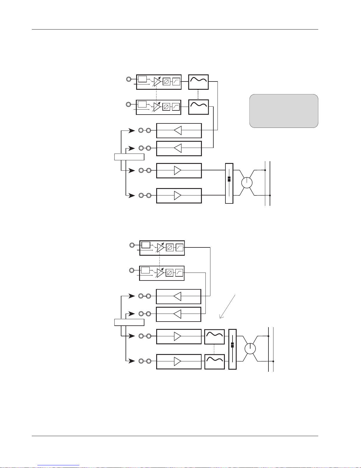
Section 4: Tutorial
Insert Diagrams,
Pre- & Post-EQ
Insert send
patch points
Insert return
patch points
At this point, you should patch an external device, such as a stereo limiter,
across the Out1/L1 and Out2/L2 insert points. The signal flow looks like this:
EQ1
M1
M2
Stereo Limiter
PWR
PWR
4 Band EQ
Stereo Links
SIDE NOTE:
When an EQ and an Out are
4 Band EQ
EQ2
OUT1
OUT2
L1
Line Input 1
L2
Line Input 2
LF
both assigned to the same
source, the EQ always comes
first in the signal path.
STEREO 1 BUS
L R
BAL
Insert send
patch points
Insert return
patch points
To put the EQ post-insert point, change the EQ source from M1 & M2 to L1 &
L2 to produce this signal path:
M1
M2
PWR
Stereo Links
PWR
EQ1 & EQ2 placed after L1 & L2
instead of M1 & M2
STEREO 1 BUS
L R
BAL
LF
Stereo Limiter
OUT1
OUT2
L1
Line Input 1
L2
Line Input 2
EQ1
4 Band EQ
4 Band EQ
EQ2
To bypass the insert point, select M1 and M2 rather than L1 & L2 as the
sources for both the EQ and the fader (this can be done with one button press
using the SnapShot Recall system).
This concludes Exercise 2.
4 - 20 Euphonix CS3000/2000 Operation Manual
Page 91
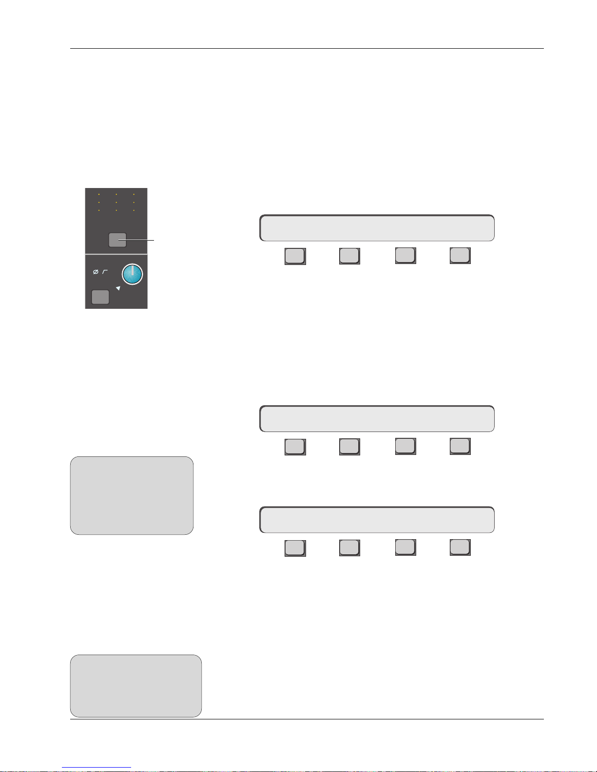
Section 4: Tutorial
B
Exercise 3
Multitrack
Monitoring
Clear Channel
M
12
L
12
L
34
Out 1 Out 2 Out 3
Clear Block
Pwr
Pad
M
L
L
12
12
34
M1
ovld
M
L
L
12
12
34
Channel
attention
key
The next group of exercises and examples will require a multitrack recording
system. Multitrack returns are usually normalled to Line Input 4 (L4) and/or to
Universal Input 2 (M2) because of their unique bus/tape switching capabilities.
We will assume your multitrack is normalled to L4 on channels 1-24. If it is
not, you will need to use the appropriate source when we specify L4. First let’s
set up a monitor mix on the lower faders.
Start by clearing channels 1 through 24. Press channel 1’s channel block
attention key at the very top of the channel strip. Next press the [Clr] key on
the Master Control Panel. You will see the following message in the SmartDisplay prompting you to confirm:
1CH–> Sure? Yes [No]
F3F1 F2 F4
Press [F3] and channel 1 will be cleared of all routing, levels will be fully
attenuated, and EQs will be zeroed.
Clearing can be done on an individual block basis as well. To do this, press the
block attention key instead of the channel attention key before pressing the
[Clr] key.
Copy Channel
Next, copy the cleared channel 1 into channels 2 through 24. Make sure you
have attention of channel 1 by again pressing 1’s channel attention key.
SIDE NOTE:
When copying whole channel or
block settings, levels for faders,
pans, auxes, UIAs, EQ parameters and MT assignments are
NOT copied. However, all other
routing information is copied.
Channel Menu
Press [F1] and you will see the following in the SmartDisplay asking you to
select the channels to copy to:
Copy Function
1CH–> OUTS METER Route
F3F1 F2 F4
????<-1 entire Channel
F3F1 F2 F4
Now, channel 1’s contents (cleared in this case), will be copied into any
channel whose channel block attention key you press. Press channel attention
keys 2-24 or the DSC’s channel/route select keys.
Copy Block
SIDE NOTE:
MT assignments will NOT be
copied with block copy. They must
be copied using a channel’s
attention key and subsequent
ASGN menu item.
Like clearing, copying can also be done on an individual block-by-block basis.
To copy a block, press the block attention key instead of the channel attention
key before pressing [F1]. Pressing subsequent block keys will copy the settings
across to new blocks. If no keys are pressed after F1, the copy function will
time out and the SmartDisplay will revert to the Channel/Block menu.
Euphonix CS3000/2000 Operation Manual 4 - 21
Page 92

Section 4: Tutorial
Clear/Copy Objects
Recalling the Default
Snapshot
(Zeroing the Console)
Clearing/copying may also be performed on objects such as Pan, Faders, etc.
Instead of having to copy cleared channel strips throughout the console to
clear it (zero the controls), a “default” SnapShot has been provided in software
and can be recalled at any time.
To recall the default SnapShot via the Assignable keys, press the DSC
[SnapShot], [Pg 4] and then [DEFAULT] key:
10
11
12
13
14
9
Recalls Default
49
50
1
2
3
4
5
6
DEFAULT
Snapshot
7
PHYSICAL
15
8
Pg 1 Pg 2 Pg 3 Pg 4
Pg 1 Pg 2 Pg 3 Pg 4
Mon
Mon
Select
Select
Preset Macro
Mon
Preset Macro
Mon
Cnfg
Cnfg
AUTONULL
Studio
Studio
Faders
Faders
16
Store
Store
Snap
Snap
Shot
Shot
Now press the SmartDisplay [F3] (Yes) key to confirm:
Sure ? Yes [No]
F3F1 F2 F4
Remember that when you recall the default Snapshot, you lose the current
settings on the desk. If you don’t want to lose the settings, save them to a
SnapShot location first.
4 - 22 Euphonix CS3000/2000 Operation Manual
Page 93
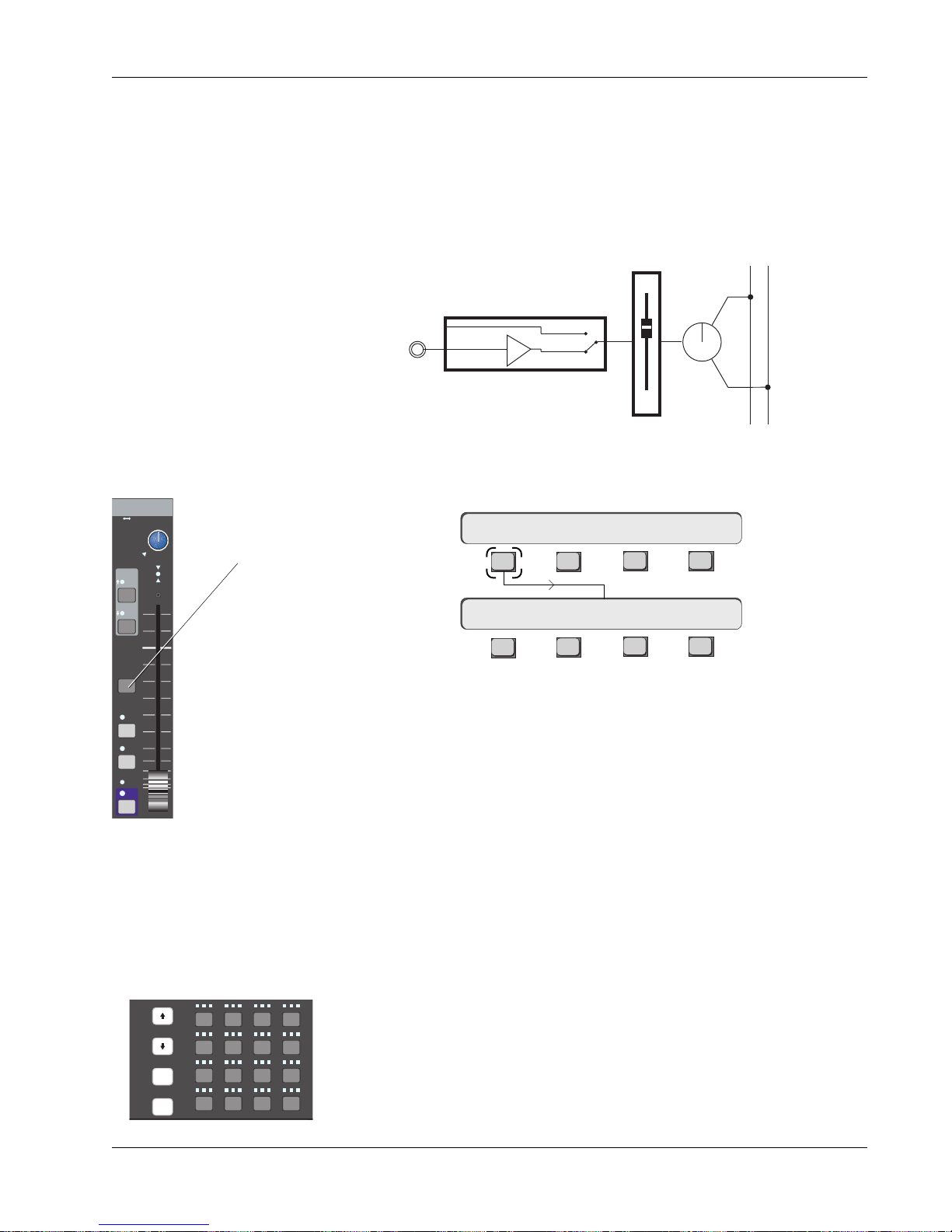
Section 4: Tutorial
Construct Signal Path
Block Copy
Input
M1 M2
L1 L2
L3 L4
EQ•Dyn
ovld
12L
Fader block key
PAN BAL
Press channel 1’s lower fader block key. Select [L4] as its source, [ST1] as its
assignment and the mode to #5 (Mono Pan). The button sequence is:
1. Press Ch 1 [LF block key] and go to the Master Control Panel.
2. Press [L4] Dedicated Key (sources the fader from L4 input).
3. Press [ST1] Dedicated Key (sends the fader to Stereo bus 1).
4. Select Mode 5 (Mono Pan) using the SpinKnob or DSC keypad.
The signal flow now looks like this:
L4
BUS
Line Input 4
LF
STEREO 1 BUS
PAN
L R
Next we will do a block copy of channel 1’s lower fader routing and mode into
channel 2 through 24. Press channel 1’s lower fader block key and then [F1]:
1LF–> SRC MODE ASGN
F3F1 F2 F4
R
BUS
DIR
ST1
ST2
PFL
AFL
Grp
ON
Copy One Setting
Slct
REC
onln
Slct
REC
onln
Slct
Solo
REC
onln
Route
!1@2#3$
123
Q W E
tab
25
26A27S28
shft
38Z39X40
37
spc
????<–LF SRC/MD/ASGN
F3F1 F2 F4
Press the lower fader block key on channels 2-24 successively.
Remember that the copy function will time out after 10 seconds if no block
keys are pressed, so don’t hesitate too long after you engage the copy function. If the copy function does time out before your finished copying, you will
need to press [F1] again to re-engage. After the last channel is copied, either
wait for the Copy mode to time out or press the DSC [Esc] key to cancel copy.
To copy just one setting within a block, first go to that menu in the SmartDisplay before copying. For example, to copy just the mode setting, first press
channel 1’s lower fader block attention key. Then press [F3] to select the Mode
menu (it should be in #5, MnPan mode). Now press [F1]. The display shows
that only the mode setting will be copied. Pressing another channel’s block
attention key will copy only the mode across. Basically, whatever is shown in
the right side of the SmartDisplay in Copy mode will be copied across giving
4
1613 14 15
absolute control over what is copied from one block or channel to another.
4
As a convenient alternative, you can use the DSC’s Channel/Route Select keys
to direct attention and carry out your copy operations.
D
C
Euphonix CS3000/2000 Operation Manual 4 - 23
Page 94
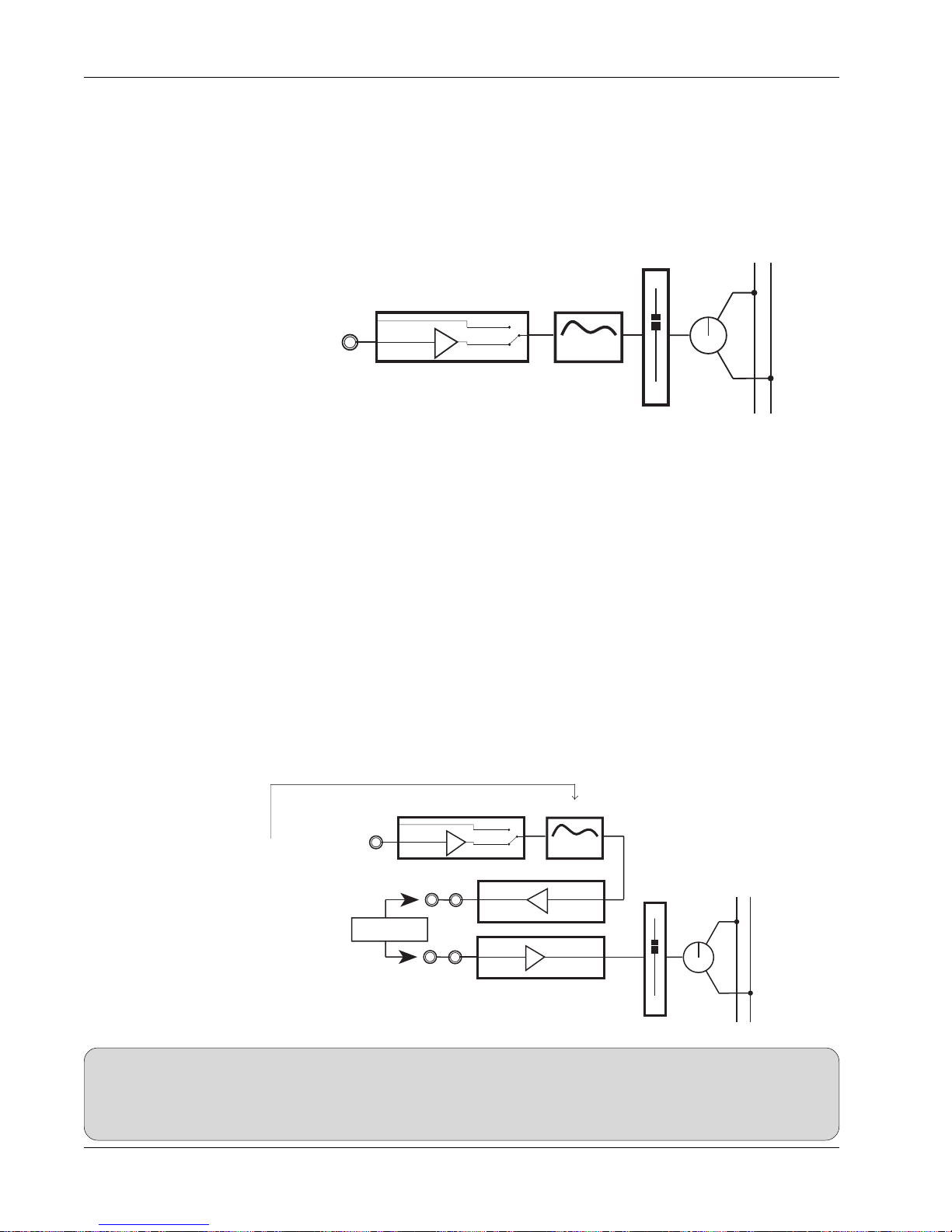
Section 4: Tutorial
Sound!
Add EQ
I/O Metering for
Multitracking
Turn the faders on and bring up their levels. Assuming the Monitor section is
set up from Exercise 1, you should be able to do a monitor mix of your multitrack program to ST1.
To add EQ to an input, press the desired channel’s [EQ•Dyn](1) attention key.
Source the EQ from L4 by pressing the [L4] Dedicated key. This will insert the
EQ into circuit.
STEREO 1 BUS
The signal flow now looks like:
L4
BUS
Line Input 4
4 Band EQ
PAN
LF
L R
Don’t forget to save your work to a SnapShot as the mix progresses, and
remember to save your title.
Go to the I/O Meter menu (from the Main menu or the DSC Mtrs key) and
select L4 for the right meter. Press [F2] to direct attention to the left meter and
select MT. These assignments meter multitrack bus out (MT) and L4 together
allowing you to see both the multitrack send and the return.
Mono Insert Point
We will use Output 3 and Line Input 3 for our insert send/return. Source Out3
from L4 and source the lower fader from L3. Switch the insert in and out by
toggling the fader source between L3 and L4 (L3 in, L4 out). The insert send is
Out3’s patch point and the return is L3’s patch point. The ES108A Dynamics
processor, or other outboard processor, can be patched in at this time.
This is our signal path now. It is a mono path with pre-insert EQ:
L4
BUS
Line Input 4
4 Band EQ
Pre-insert EQ
STEREO 1 BUS
L R
PAN
Dynamics
Processor
OUT3
L3
Line Output 3
Line Input 3
LF
SIDE NOTE:
Remember to de-assign inserts when not needed. There is no normalling of insert send/returns at the patchbay, so if no device is
patched or normalled into the insert send/return loop, the signal path will not be complete and no signal will reach the fader. In
systems outfitted with 2 dynamics processors per channel, the insert send/return pairs Out1/L1 and Out2/L2 are usually
normalled through the ES108A processors. The normalling is done at the patchbay.
4 - 24 Euphonix CS3000/2000 Operation Manual
Page 95
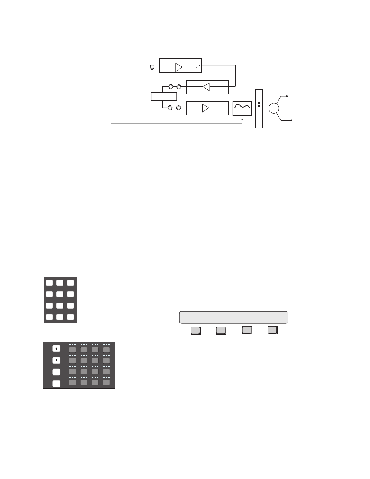
Section 4: Tutorial
789
456
123
0 Enter Del
As with our stereo channel inserts from Exercise 2, the EQ is placed postinsert point by sourcing the EQ from L3 rather than L4:
Post-insert EQ
Exercise 4
Multitrack Routing
Source
OUT3
L3
BUS
Line Input 4
Line Output 3
Line Input 3
4 Band EQ
STEREO 1 BUS
L R
PAN
LF
L4
Dynamics
Processor
If you have assigned an insert loop, either complete the loop using patch
cables, insert a processor device, or un-assign the inserts before continuing.
This concludes Exercise 3. Make sure to save your work in a new snapshot
location.
This exercise looks at routing the signal (microphones, instruments, etc.) to the
multitrack recording system. We will route the input signal (in this case a
microphone), to the multitrack via the upper fader.
Make sure the monitor Level pots are turned down to avoid the possibility of
acoustic feedback. Plug a microphone into channel 1’s M1 patch point. Set up
the gain and phantom power by selecting the correct options from M1’s input
block (see Universal Input Amplifiers earlier in this section). Press channel 1’s
upper fader block key and select the [M1] input using the DSC Dedicated Keys.
This connects the microphone to the upper fader.
Assign
From the SRC menu, pressing [F2] will cycle the SmartDisplay menu through
the three setup menus, SRC, MODE, & ASGN. Go to the ASGN menu or just
press the [+Bus] key as a shortcut:
1UF->ASGN MT ?
DSC Keypad
F3F1 F2 F4
or
Slct
REC
onln
Slct
REC
onln
Slct
Solo
REC
onln
Route
!1@2#3$
123
Q W E
tab
25
26A27S28
shft
38Z39X40
37
spc
4
4
1613 14 15
D
C
You are being asked to select a multitrack bus. Enter the desired bus numbers
(1 and 2 for the sake of our exercise), from the numeric keypad and then press
Enter after each assignment. Observe the bus assignment area of channel 1’s
upper fader. You will see that the bus numbers you’ve assigned are lit. A more
expedient way to accomplish this is to use the DSC Channel Selection keys.
Make sure the up arrow located to the left of the Assignable Key is lit to
DSC Channel Selection keys
select the upper fader. Press the [Route] key to put the DSC Channel Selection
keys into Route mode. Press the desired keys to assign multitrack buses.
Mode
Press [F2] again to cycle to the MODE menu. If you have a mono source and
you intend to pan between a pair of multitrack buses, set the mode to “Mono
Pan”. If you have a mono source and you want to assign it to only one bus or
Euphonix CS3000/2000 Operation Manual 4 - 25
Page 96

Section 4: Tutorial
equally to two buses, select Mono mode. For this experiment choose “Mono
Pan” mode. The M1 signal is now assigned via the upper fader and pan, to
multitrack buses 1 and 2. This follows standard conventions of an I/O strip.
Bus Summing Amps
MT Bus to Out3
The signal is sent down buses 1 & 2 to the associated bus summing amps. As
in conventional in-line consoles, the summing amp resides in the I/O of the
same number, (i.e., bus amp 1 resides in channel 1, bus 2 in channel 2, etc.).
From there the signal is sent out DIR1 & DIR2 of the channel. DIR1 & DIR2
output assignments default to the multitrack bus output. There will be more
information on DIRs later in this section.
If the multitrack machine is switched to input, you will be able to monitor the
signal by bringing up lower faders 1 & 2, as they should already be on
(unmuted) and routed to ST1.
For certain signal routing situations, the MT bus can be sent from Out3. This is
useful when the Dir 1 & Dir 2 connectors must be used to feed a 2/channel
Cube for example. Another example may be to obtain a stereo post fader
direct feed using Dir 1/2.
To set the Out3/MT routing, press the channel attention key at the top of the
channel, [F2] (OUTs) and then [F4] (OUT3):
16CH-> OUT1 OUT2 OUT316CH-> OUTs METER Route
F3F1 F2 F4
F3F1 F2 F4
M1 M2
L1 L2
L3 L4
33
60
UL
B
M
12
L
12
L
34
Out 1 Out 2 Out 3
M
L
L
F
12
12
34
60
M
L
L
12
12
34
33
16CH->OUT3 ?
F3F1 F2 F4
Now press the [+Bus] or [F3] keys to assign the MT bus to Out3.
1CH->OUT3 MT
F3F1 F2 F4
If M1 had been previously set as the Out3 source, MT replaces it. You may
also use the DSC Source Assign keys to assign additional sources to Out3.
When MT is selected to the Out3 bus, the M1 Out3 channel I/O source matrix
LED remains lit (for both M1 and MT assignments) along with the B LED (MT
for the CS2000).
Indicates MT selected as Out3 source
Out3, M1 designation
4 - 26 Euphonix CS3000/2000 Operation Manual
Page 97

Section 4: Tutorial
B
L4 Bus/Tape
Switching
M
12
12
34
Pwr
Pad
L
L
M1
12
12
34
ovld
M
L
L
12
12
34
16CH–> OUTs METER Route
M
L
L
Out 1 Out 2 Out 3
Querying a
Channel’s Bus/Line
Routing
As mentioned earlier, it is common to normal multitrack outputs to L4 because
the L4 input can be switched to monitor either the machine output (normal
setting) or the bus feed. Switch between L4 return and bus output by pressing
the channel attention key at the top of the channel I/O strip, [F4] (Route), [F2]
(L4) and then press [F3] for Bus or [F4] for Line (Tape) return:
16CH–> L4 DIRs CMB
F3F1 F2 F4
16CH–>L4 IN: BUS LINE
F3F1 F2 F4
F3F1 F2 F4
Line 4 Bus/Tape Menu
Routing Menu
When viewing an individual channel’s meter settings and L4 is selected as the
meter source, you will see an arrow to the left of the L4 designation:
16CH->Aud:OFF Aud->L4
F3F1 F2 F4
The arrow designates whether the L4 source is currently coming from the line
feed in the patchbay or from the MT Bus. An
nates Bus mode while a
downward pointing arrow
upward pointing arrow
designates a Line/Tape
desig-
feed. L4 sourcing, however, cannot be changed from this menu. The arrow is
shown here just a convenient way to determine where your signal is currently
sourced from. This indication is not available via the global [Mtrs] key.
Adding EQ To M1
To EQ the M1 input, simply select EQ1 on channel 1 and source it from M1.
There are two EQs per channel, so both the source mic on the upper fader and
the tape return on the lower fader can be EQed.
Saving to a Snapshot
The console is now configured for mixing the multitrack program on the lower
faders. Save this basic configuration to a snapshot and name it “Basic Mix
Setup”, for example. Now whenever you start a mix, you won’t need to
reconstruct this setup from scratch. Just recall your “Basic Mix Setup” snapshot (channel 1 is also set for tracking in this snapshot).
Euphonix CS3000/2000 Operation Manual 4 - 27
Page 98

Section 4: Tutorial
The signal path now looks like this:
M1
PWR
4 Band EQ
Multitrack Buses
12
PAN
Stereo Inputs to
Multitrack
Multitrack
Machine
Effects
Device
Channel 1
Upper Fader
Channel 1
Lower Fader
DIR1
L4
OUT3
L3
Mic Source Signal Path
Multitrack Monitor Signal Path
Direct Out 1
BUS
Line Input 4
Line Output 3
Line Input 3
∑
4 Band EQ
UF
Bus
Summing
Amp
LF
STEREO 1 BUS
L R
PAN
A stereo microphone, or a pair of microphones, can be routed to the multitrack
buses using only one fader. To route a stereo mic to tape, source channel 1’s
upper fader from both M1 & M2. Next, select fader mode 7: Stereo. Now link
M1 & M2 together by pressing either of the M1/M2 block keys, and pressing
the [*ST] key. You can also insert a stereo EQ on these inputs and link them by
selecting the source of EQ1 & EQ2 to be M1 & M2 respectively. Now route the
upper fader to a pair of multitrack buses.
The signal path will look like this:
This concludes Exercise 4.
4 - 28 Euphonix CS3000/2000 Operation Manual
M1
M2
PWR
PWR
Stereo Links
EQ1
4 Band EQ
4 Band EQ
EQ2
Multitrack Buses
odd
BAL
even
UF
Page 99

Section 4: Tutorial
Auxiliary Sends
Overview
A1
ON
BAL
ovld
A2
ON
ovld
Aux Master A1 & A2
Aux Modes
There are eight (8) auxiliary send buses which have their master gain controls
labelled A1 to A8 in the upper part of the CS3000/2000 Master Module. Each
of the eight masters has a gain control and an on/off key.
There are four (4) aux send controls on every CS3000/2000 Mix Controller
channel I/O strip labelled A, B, C and D and divided into two console aux
blocks (A/B) & (C/D). Each of the controls is capable of independent addressable operation, can be sourced from any of the channel’s six (6) inputs and
assigned to any of the eight aux buses. The controls can be configured as
individual level controls or combined into level/pan pairs, deriving signal either
pre or post, Upper or Lower fader.
In order to configure the aux sends, you need to determine from where the aux
signals are to be sourced. Traditionally, these sources tend to be signals from
console faders.
There are three styles or modes of aux sends:
1. Mono In/Mono Out
2. Mono In/Stereo Out
3. Stereo In/Stereo Out
The console default for an unconfigured aux block is Mono In/Mono Out
a.k.a..
Mono Independent mode. This mode sums all source selections made to the
control and sends the summed signal equally to all bus assignments.
Exercise 5
Mono Independent
Mode
SIDE NOTE:
Since aux sends A/B and C/D share their
respective aux blocks, the DSC [left
arrow] and [right arrow] keys are used
to direct attention between them.
For the sake of clarity, we will start all exercises with an unconfigured aux
send. Use the DSC [Clr] key to clear your selected aux send. We will also
assume that channel 16’s lower fader is sourced from L4 as a tape return and
assigned to the ST1 bus output.
In this exercise, we will setup aux sends A thru D to feed aux buses 1 thru 4
respectively.
Press channel 16’s aux A/B block attention key to display the Aux Status menu:
Aux Status Menu
16A-> ON pre
F3F1 F2 F4
Left and right DSC arrow keys
The console default is pre fader, aux send ON.
Confirm that console attention
is directed to aux send A. (See side note) Pressing an aux block attention key
always gives you quick access to aux mutes (F2) and pre/Post routing (F3).
Euphonix CS3000/2000 Operation Manual 4 - 29
Page 100
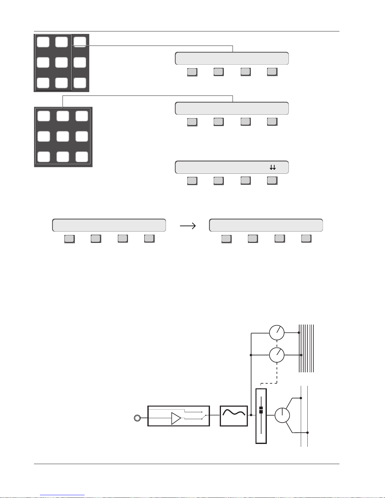
Section 4: Tutorial
M1 M2 DIR
L1 L2 ST1
L3 L4 ST2
789
456
123
Press the DSC [L4] key to directly assign the aux source routing:
Aux Source Menu
16A-> L4<-p. .
F3F1 F2 F4
Press the DSC keypad [1] key to directly assign the aux send to aux bus 1:
Aux Assign Menu
16A-> BUS 1
F3F1 F2 F4
Press the DSC [right arrow] key to direct attention to aux send B. Confirm
that B is now displayed in the SmartDisplay menu:
16B-> ON pre
F3F1 F2 F4
As before, press the [L4] key to directly assign the aux source routing and then
press the DSC keypad [2] key to directly assign aux send B to aux bus 2:
16B-> L4<-p. .
F3F1 F2 F4
Press channel 16’s aux C/D block attention key to display the aux menu. As
before, confirm that C is now displayed in the SmartDisplay menu.
Repeat the previous steps for aux sends C and D. Once completed, you can
verify routing by feeding a test tone to L4 and trying the aux sends. Be sure the
aux bus master controls are turned up and unmuted. Here is a typical signal
flow diagram for Aux sends A and B:
16B-> BUS 2
Mono Independent
Post Lower Fader
F3F1 F2 F4
Aux A
Aux B
Link
AUX BUS
1 - 8
STEREO 1 BUS
L R
This concludes Exercise 5.
4 - 30 Euphonix CS3000/2000 Operation Manual
L4
BUS
Line Input 4
4 Band EQ
PAN
LF
 Loading...