

Page 1
Euphonix CO-600 Change-Over System
For New Core DF66 Redundancy
Install and Operation Notes
Document Revision: A
Part Number: 840-10493-01
Release Date: December 2007
Euphonix, Inc.
220 Portage Ave.
Palo Alto, California 94306
Phone: 650-855-0400
Fax: 650-855-0410
Web: http://www.euphonix.com
e-mail: info@euphonix.com
Page 2

In the interest of continued product development, Euphonix reserves the right to make
improvements to this manual and the product it describes at any time, without notice or
obligation.
System 5, S5, PatchNet, eMix, EuCon, R1, Studio Hub, Audio Deck, Max Air, Reel Feel, Clear
Displays, Track Panner, SnapShot Recall, DSC (Digital Studio Controller), Hyper-Surround,
Total Automation and Mix View are trademarks of Euphonix, Inc.
Manual written by Martin Lucas, Edward Jones, Ted Wolfe, and Rob Wenig.
©2007 Euphonix, Inc. All rights reserved worldwide. No part of this publication may be
reproduced, transmitted, transcribed, stored in a retrieval system, or translated into any language
in any form by any means without written permission from Euphonix, Inc.
Note: This equipment has been tested and found to comply with the limits for a Class A
digital device pursuant to Part 15 of the FCC Rules. These limits are designed to
provide reasonable protection against harmful interference when the equipment is
operated in a commercial environment. This equipment generates, uses, and can
radiate radio frequency energy and, if not installed and used in accordance with
the instruction manual, may cause harmful interference to radio communications.
Operation of this equipment in a residential area is likely to cause harmful interference in which case the user will be required to correct the interference at his own
expense.
Caution: Any changes or modications made by the user that are not expressly approved
by Euphonix could void the user’s right to operate the equipment.
Page 3
IMPORTANT SAFETY INSTRUCTIONS
The lighting ash with arrowhead symbol within an equilateral triangle, is
intended to alert the user to the presence of uninsulated “dangerous voltage”
within the product’s enclosure that may be of sufcient magnitude to constitute a
risk of electrical shock to persons.
The exclamation point within an equilateral triangle, is intended to alert the user
to the presence of important operating and maintenance (servicing) instructions
in the literature accompanying the product.
Read these instructions.1)
Keep these instructions.2)
Heed all warnings.3)
Follow all instructions.4)
Do not use this apparatus near water.5)
Clean only with a dry cloth.6)
Do not block any ventilation openings. Install in accordance with the manufacturer’s 7)
instructions.
Do not install near any heat sources such as radiators, heat registers, stoves, or other 8)
apparatus (including ampliers) that produce heat.
Do not defeat the safety purpose of the polarized or grounding-type plug. A polarized plug 9)
has two blades with one wider than the other. A grounding type plug has two blades and a
third grounding prong. The wider blade or the third prong are provided for your safety. If
the provided plug does not t into your outlet, consult an electrician for replacement of the
obsolete outlet.
Protect the power cord from being walked on or pinched particularly at plugs, convenience 10)
receptacles, and the point where they exit from the apparatus.
Only use attachments/accessories specied by the manufacturer.11)
Use only with the cart, stand, tripod, bracket, or table specied by the manufacturer, or 12)
sold with the apparatus. When a cart is used, use caution when moving the cart/apparatus
combination to avoid injury from tip-over.
Page 4

Unplug this apparatus during lightning storms or when unused for long periods of time.13)
Refer all servicing to qualied service personnel. Servicing is required when the apparatus 14)
has been damaged in any way, such as power-supply cord or plug is damaged, liquid has
been spilled or objects have fallen into the apparatus, the apparatus has been exposed to rain
or moisture, does not operate normally, or has been dropped.
WARNING – TO REDUCE THE RISK OF FIRE OR ELECTRIC SHOCK, DO NOT 15)
EXPOSE THIS APPARATUS TO RAIN OR MOISTURE.
Do not expose this equipment to dripping or splashing and ensure that no objects lled with 16)
liquids, such as vases, are placed on the equipment.
To completely disconnect this equipment from the AC Mains, disconnect the power supply 17)
cord plug from the AC receptacle.
The mains plug of the power supply cord shall remain readily operable.18)
This unit is provided with a power supply cord set suitable for 120V AC input only (for 19)
U.S.A. and Canada). For other than U.S.A. and Canada, a qualied person must provide for
use with this unit, an appropriate, approved power supply cord set which is in compliance
with the end use country requirements and has a minimum cross-sectional area of 1.0mm².
For units with more than one power cord:20)
Caution: This unit has more than one power supply cord. Disconnect two power
supply cords before servicing to avoid electrical shock.
Attention: Cet appareil comporte plus d’un cordon d’alimentation. An de prévenir les
chocs électriques, débrancher les deux cordons d’alimentation avant de faire
le dépannage.
Operator Accessible Fuse:21)
Caution: For continued protection against risk of re, replace only with same type and
rating of fuse.
Attention: Pour ne pas compromettre la protection contre les risques d’incendie,
remplacer par un fusible de même type et de même caractéristiques
nominales.
Page 5

Euphonix CO-600 Change-Over System For New Core DF66 Redundancy
Important Note!
Due to the “Hot Swap” capabilities of all card components in the COS chassis, power can be
applied to the unit at any time before after or during card installation. It is recommended,
however, that this feature only be used when necessary.
This is because the hot swap system can not protect from all possible errors made by the
operator during card installation.
Powered on cards are susceptible to damage from accidental shorting due to conductive
jewelry, excessive card deection, or mis-aligned insertion or cards. To insert or remove
cards while the chassis power is applied, rst carefully read instructions in this manual to
prevent damage to equipment.
5
Page 6
Euphonix CO-600 Change-Over System For New Core DF66 Redundancy
Overview
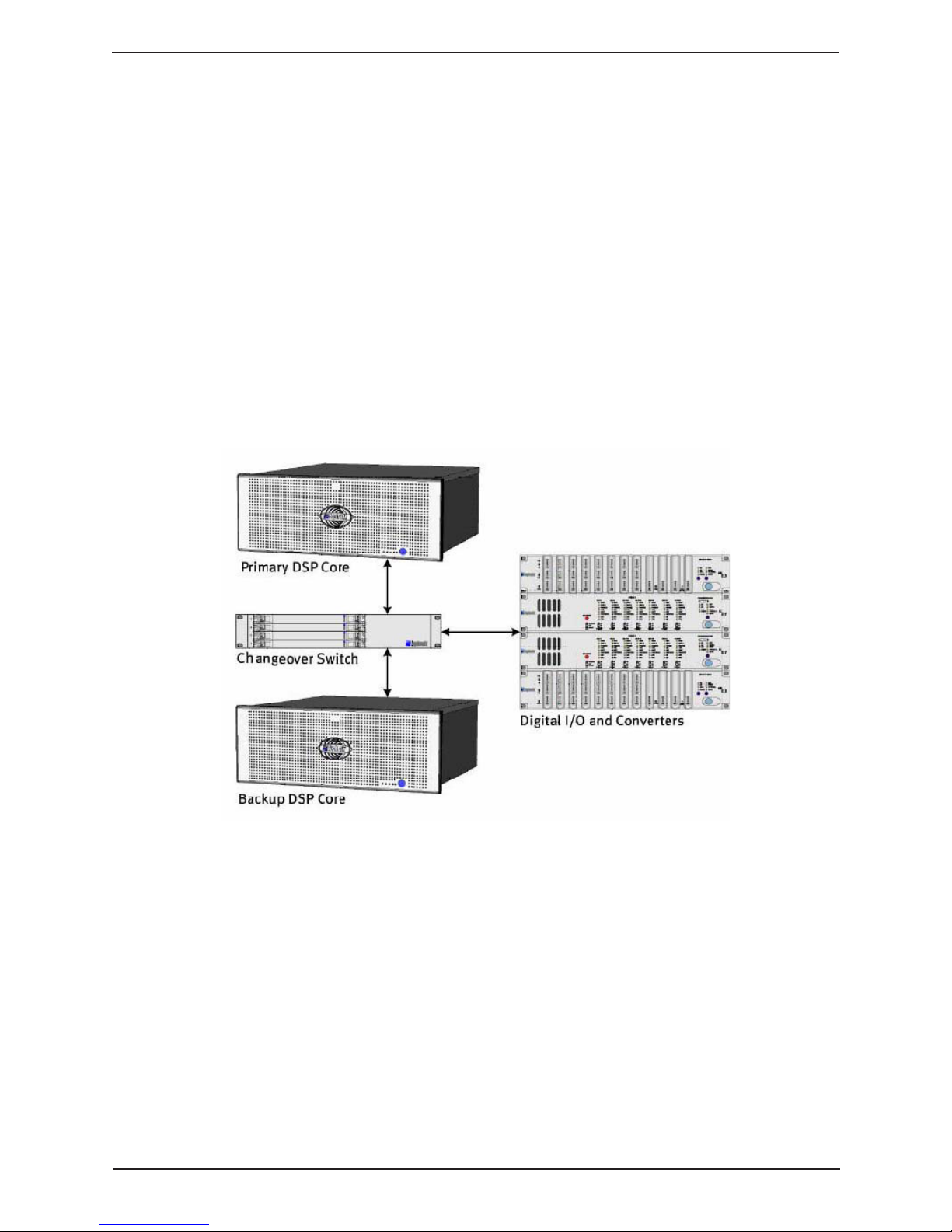
The change over redundancy system allows running a backup DF-66 SuperCore in
parallel with the primary unit. The change over switch distributes all audio signals to
both the primary and backup DSP cores. If the diagnostics system detects a fault, or even
a potential primary DF-66 failure, the entire output audio path (including all I/O devices)
is switched over to the backup system. This can occur automatically or be initiated by
the console operator. Setup for this is available in the Status page of either Emix or
MaxAir Application.
Each card in the Change Over chassis can accommodate all of the I/O for one SP662
card in the primary and backup DF66 SuperCores. You don’t require a Change Over
card for each Core card just the number of I/O needed. An Ethernet connection to the S5/
MaxAir network is required. Emix/MaxAir displays the status in the system page with
full diagnostics.
6
Page 7

Euphonix CO-600 Change-Over System For New Core DF66 Redundancy
The CO-600 has two primary functions: 1) a MADI splitter that provides 2 MADI
outputs for each MADI input and 2) a MADI switchover that switches each MADI
output between Primary and Backup MADI sources. Figure 1 provides a conceptual
block diagram of signal ow and behavior. External MADI inputs are distributed to both
the Primary Core and the Secondary Core so that the sources are always available to both
cores. The MADI outputs from each core are connected to the CO-600 and available for
switchover during a technical fault. The unpowered state of the system is connectivity
to the Primary Core.
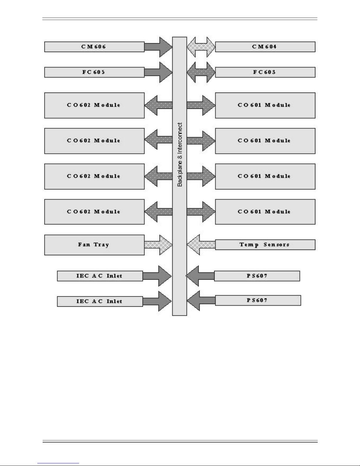
A conceptual block diagram of a single CO-600 is provided in Figure 2. Features
available include redundant PSU’s with dual IEC AC inlets, GPIO, Fan Tray, CMM,
Chassis Control module, Chassis control linking, environmental sensors, Ethernet, and
up to four Change-over cards.
Signal Flow and BehaviorFigure 1
7
Page 8
Euphonix CO-600 Change-Over System For New Core DF66 Redundancy
Chassis Management
Provision for the optional CM604/CM606 is be provided. The CM604 queries information
such as eld replaceable unit status, presence, and performs health monitoring of
system components. It also controls, when present, the power-up sequencing of each
component and the power-on/off to each slot. It is designed to work in conjunction with
GrassValley’s NetCentral™ remote facility monitoring SNMP software.
Single CO-600Figure 2
8
Page 9
Euphonix CO-600 Change-Over System For New Core DF66 Redundancy
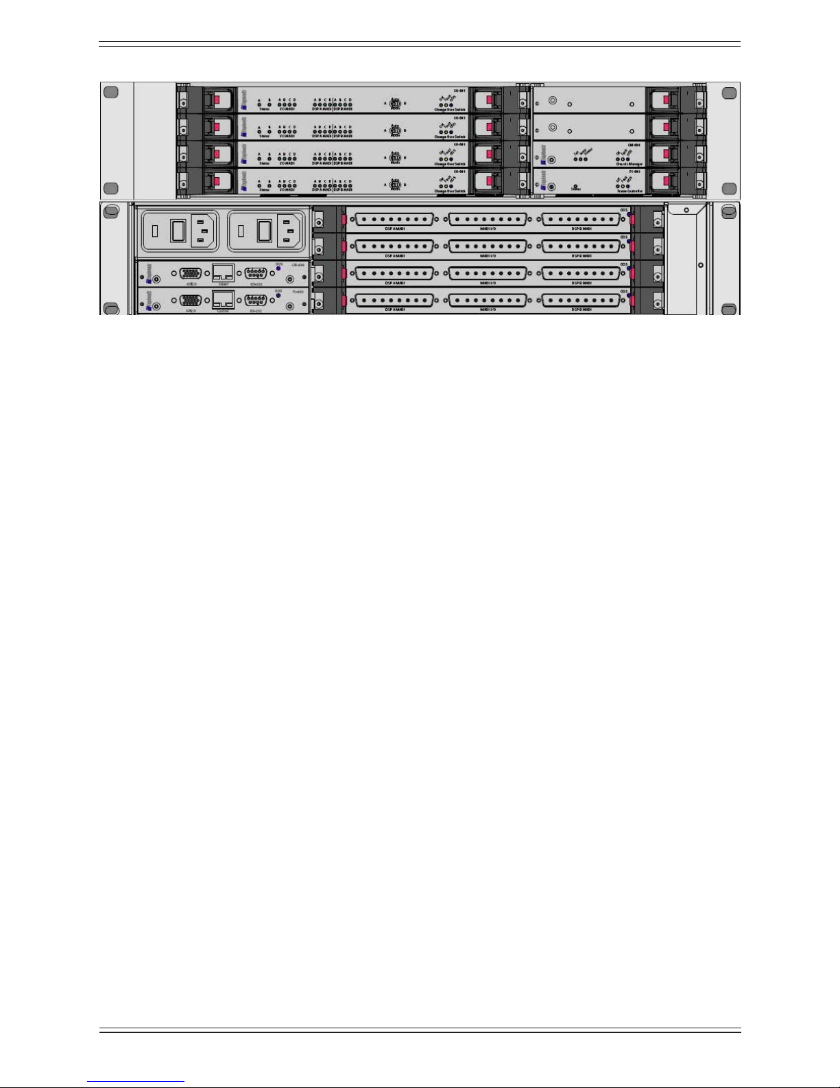
Front and Rear PanelsFigure 3
Front Panel
The front of the unit consists of eight card slots in a 2U chassis. The four full-length slots
on the left side can be lled with change over cards. The four half-length slots on the
right side are used for two hot swappable power supply modules, a frame controller card
and a SNMP chassis management card.
Indicators
Each of the change over cards provides indication of the current switch state (A or B
selected for output), input MADI signal presence, card status, out of service and fault
status. Power supply modules have power on indication and the frame controller card
has a processor active indicator. The chassis management card has additional power,
temperature and cooling status indication.
Front Panel Control
There is a switch located on the front of each change over card that allows local manual
override of the output relay position in the event of a control system failure. In the Auto
(middle) position, the remote control input on the change over frame controller card
determines which output is active.
Rear Panel
The rear panel of the unit has four full-length card slots on the right side for MADI I/O
modules.
Each module supports four MADI signals (up to 256 channels) connected to and from the
I/O, primary and backup DSP cores. With four cards in the chassis, the change over unit
can support up to 1024 audio channels. The left side of the rear panel has four half-height
card slots. Dual power inlets for the two power supplies are 8HP (two slots) in height.
The two other slots are used for frame controller and chassis management connections.
9
Page 10

Euphonix CO-600 Change-Over System For New Core DF66 Redundancy
The frame controller connections consist of an Ethernet port, serial port and GPIO. They
can also be set to a “dead man’s switch” mode where an interruption in the input logic
signal would toggle the change over switch to the other output. An additional Ethernet
connection and serial port in the upper slot are for a separate chassis management card
(SNMP) described below.
Fail Safe
Even if you lose power to the whole unit, the cards automatically insert relays to route
MADI to and from the Primary Core, preventing audio loss.
SNMP Monitoring
The SNMP chassis management controller monitors operating conditions and noties
the user to take action to avert system failure. It provides a simple way to manage remote
monitor devices and adds a dimension of security to critical applications. The chassis
management controller works in conjunction with GrassValley’s NetCentral™ facility
monitoring software.
Features
Fan speed, internal temperature, power supply status and voltage status •
monitoring.
Independent system monitoring.•
Remote alarm notication.•
High reliability components including redundant power supplies.•
High MTBF and low MTTR.•
Power on, Boot and Reset
The system is able to reach full operational status within 10 seconds of turning on of the
AC Mains power or after the instantiation of system reset. As an additional reliability
feature, the CO-600 provides connectivity on the primary MADI paths when not
powered.
Controls
The CO-600 provides four methods for controlling the routing state of the cards:
Ethernet for integration with EMix and MaxAir 1.
Serial control2.
Front panel local switch on each Change Over module’s front panel, and 3.
GPI closure control. 4.
10
Page 11

Euphonix CO-600 Change-Over System For New Core DF66 Redundancy
Detailed Description and Service Info
The Change-Over System (COS) Chassis is designed to provide automated or manual
switching between redundant MADI streams in a critical production environment. It
does this by grouping redundant MADI media in sets of 4 MADI ins and 4 MADI outs to
be switched as a whole, then allowing up to four groups be switched by a single chassis.
Multiple Chassis can be daisy chained for larger scale systems. Various mechanisms
provide for the automatic and manual switching. Slots are keyed to avoid insertion of
the wrong card.
Power Supply
A single power supply card can be installed into either one of the top two right slots in
the COS chassis. Make sure the ejector clips are completely latched. Be careful during
installation that the card is aligned in the slot grooves for the card.
Due to the thickness of the pins used to connect the card to the chassis back plane,
some insertion force will be necessary. Press on the card front with your thumbs while
operating the ejectors to help get the ejectors latched. This will prevent excessive wear
on the plastic ejector mechanism.
Be aware that there is a specic IEC power connector on the rear of the chassis for each
power supply. The power supply card will only operate if the correct IEC power cord
is connected.
If two power supply cards are installed, they can be installed in either order.
Controller Card
Only one Controller card (FC 603) can be installed in a chassis. Install a Controller
Front in the bottom front controller slot on the right side of the chassis.
Make sure the ejector clips are completely latched. The card should not require excessive
force to insert, if the card does not seem to insert, check that the card is sliding evenly in
the slot grooves and that the alignment pins near the ejector clips are guiding card during
the last portion of insertion.
Install a Controller Rear card (FC 605) in the bottom rear controller slot on the right side
of the chassis. Use the same care in installing the rear card as the front card. Make sure
the ejector clips are completely latched.
Do not attempt to plug a Controller front/rear card into the identical CMM slot above it.
The cards may be damaged, and unexpected operation will occur.
11
Page 12

Euphonix CO-600 Change-Over System For New Core DF66 Redundancy
Switch Cards
Zero to four Switch Cards(CO 601) can be installed in a chassis. Switch cards can be
installed in any order or in any available positions. However, it is generally easier to
operate the COS if they are installed without gaps from the bottom to the top.
Install a Switch Front Card in an available front slot on the left side of the chassis. Make
sure the ejector clips are completely latched. Use the same care as when inserting the
Controller Front Card. In addition, note that due to the card’s size, it is easier to ex the
card and cause possible shorting or mechanical damage.
Install a Switch Rear card (CO 602) in the matching rear slot of the chassis as the front
card. Make sure the ejector clips are completely latched. Use the same care as when
inserting the Controller Rear Card. In addition, note that due to the card’s size, it is
easier to ex the card and cause possible shorting or mechanical damage.
The Switch Rear Card can be installed with cables pre-connected, but this can make
it easier for the card to be mis-aligned or improperly inserted. Use caution and avoid
excessive force.
System Connection
For each group of 4 MADI Ins and Outs, connect a 4x4 MADI D-Shell connector from a
DSP Card in the primary DSP unit to the Bank A connector of a switch card in the COS
Chassis. Connect a 4x4 MADI D-Shell connector from redundant DSP unit to the Bank
B connector of the same switch card. Connect a third 4x4 MADI D-Shell connector
from the middle I/O connector to the desired outboard MADI gear.
If network-based status and control of the COS is desired, connect a standard Ethernet
cable from the Controller Rear Card’s RJ45 jack to a network switch, router, or directly
to the studio computer.
If serial RS-232 setup of the COS is desired, connect a DB-9 M-F cable (straight thru
cable) from the Controlled Rear Card’s DB-9 jack to a computer. If long distances are
required, suitable RS-232 to RS-422 converters should be used to extend the range.
If GPIO control of the COS is desired, connect the appropriate GPIO control devices
or cables to the Sub-DB-15 jack on the Controller Rear Card. This will likely require
custom wiring on the mating connector.
12
Page 13

Euphonix CO-600 Change-Over System For New Core DF66 Redundancy
Basic Operation
Power Supplies
Power the COS unit up by plugging it into a power source. There is no power switch.
On the Power Supply Cards, check that the green “Power Good” LED is lit and the Red
“Halt” LED is not lit. If this is not the case, replace the power supply.
Hot Swap LEDs
On the Controller Front Card and any Switch Front Cards installed, there are three hotswap control LEDs. These consist of a green “OK” LED, a yellow “Fault” LED and
a blue “OOS” (out-of-service) LED. Only the green “OK” LED should be lit. These
lights can be interpreted as follows
OK Fault OOS Meaning
On Off Off Operating normally.
On On Off Temperature, Voltage or Current condition is out of tolerance, still operating.
Off On Off A failure has rendered the card inoperable.
Off Off On Front or rear card is partially ejected or software has disabled the card.
Off Off Off Boot code running, power not been applied to chassis or the card is fully
ejected.
No other combinations should be possible and indicate the card is not operational.
The blue “OOS” LED is duplicated on the Rear card for ease of use during card
exchanges.
Faults
The Controller Card’s “Fault” LED will come on and stay on if a problem is detected, no
matter how briey. The operator must intentionally clear the fault condition. A fault can
occur if any of various measured values fall outside normal operating conditions. The
unit monitors current, temperature and all voltages in the unit. It also monitors the health
of the internal microprocessors and the functionality of the software.
If the fault is not critical, the COS will continue to operate and display the green “OK”
LED. If the failure is critical (the card can not operate in this state), the green “OK”
LED will go out and the device will not communicate via any interface. Critical failures
would include serious over current or signicant failure of the main voltage rails.
To clear a critical or non-critical fault, the operator can temporarily ip the ejector latches
on the card. Or, the state can be cleared via Ethernet or serial control.
13
Page 14

Euphonix CO-600 Change-Over System For New Core DF66 Redundancy
Out-of service (OOS) LED
The out-of service LED indicates the card is partially ejected or the operator has
intentionally disabled the card. No other LEDs should be on when the “OOS” LED is
lit. The operator can only disable the Controller Card by partially ejecting the Controller
front or rear card. However, the Switch Cards can also be disabled and re-enabled via
the Ethernet and serial interfaces. If a switch card has been disabled via software, it can
be re-enabled via Ethernet or serial control. Or, it can be re-enabled by toggling the
ejector latch.
Controller Card “Status” LED
In addition to the three hot swap LEDS on all Switch and Controller Cards, the Controller
Card has an additional green “Status” LED. This LED indicates the status of the main
processor in the Controller Card. The main processor will begin booting once the green
“OK” LED lights. After a couple of seconds, the processor will nish booting and the
LED will be used to display the status of the processor.
The green “Status” LED will mostly be off if the global back plane switch is off (the global
back plane switch is used to switch all Switch Card’s relays to the Bank B redundant
connector). It will mostly be on if the global back plane switch is set to on (selecting
bank “B”). Be aware that local settings or conditions in the individual switch cards can
override the actual state of the connection.
During operation, the “Status” LED will icker lightly during Ethernet and RS-232
control to indicate communication is occurring. With Ethernet communication, this
ickering will happen about once a second even when no operations are actively being
commanded. With serial, it will generally icker only when a command is received.
Regardless of communication occurring, the “Status” LED will icker every 10 seconds
or so to act as a “heartbeat”, indicating proper operation continues.
Switch Card LED’s
The Switch Card has several additional LED’s. They consist of “Bank A” and “Bank B”
LED’s as well as 3 sets of 4 MADI lock LED’s for the primary Bank A DSP connection,
the redundant Bank B DSP connection and the I/O connection. As with the “Status”
LED on the Controller Front card, these LEDs are lit green “OK” LED when indicating
normal operating conditions. If the “OK” LED is not lit, the card’s integral bypass relays
will release and force a connection between the primary DSP Bank A connector and the
I/O connector.
The “Bank A” and “Bank B” LED’s indicate which DSP bank is currently connected to
the I/O for that card. The 12 individual MADI lock LED’s indicate if there is currently
a valid incoming MADI signal connected to that described connector.
14
Page 15

Euphonix CO-600 Change-Over System For New Core DF66 Redundancy
Front Panel Switch
Each Switch Front Card has a 3-position toggle switch, which allows for forcing either
DSP Bank connector to be connected to the I/O connector. It also has a center “Auto”
position which automatically sets the Bank A or Bank B connection based on conditions.
This toggle switch will only function when the “OK” LED is lit and the board is operating
normally. Otherwise, the bypass relay will release and force a connection between the
primary DSP Bank A connector and the I/O connector.
Automatic Operation
When a Switch Card is operational with its “OK” LED lit, and the front panel switch is
in the “Auto” position, the card selects the Bank A connector unless any of three signals
for each Switch Card is asserted. The three signals are:
Individual Back Plane Switch – a separate hardware driven signal for each 1.
individual Switch Card.
Global Back Plane Switch – a single hardware signal effecting all Switch cards 2.
simultaneously.
SPI Test Switch – a separate software driven signal for each individual Switch 3.
Card.
If any of these three signals are asserted, the Switch Card will connect the DSP Bank B
connector to the I/O connector. This condition will continue until the operator clears the
condition or power is removed.
Individual Back Plane Switch
NOTE: Not used when connected to Emix or MaxAir.
The individual back plane switch is asserted when a predened GPIO input pin is
grounded. There is one pin for each Switch Card. The condition will cause just the
indicated Switch Card to select Bank B. It will continue to select Bank B until the
condition is cleared via the Ethernet or serial interface, or by front panel control.
The operator can clear the condition by moving the front panel toggle switch for that
card to the “A” position. Setting of the individual back plane switch by GPIO input will
be prevented while the front panel switch is in the “A” position. Returning the switch to
the “Auto” position will allow the individual back plane switch to re trigger if the GPIO
input pin is still grounded.
The individual back plane switch position will be preserved through power cycles.
The individual back plane switch states are not dependent on which Switch Cards are
installed. That is, an individual back plane switch can be asserted even if no card is
installed.
15
Page 16

Euphonix CO-600 Change-Over System For New Core DF66 Redundancy
Global Back Plane Switch
NOTE: Not used when connected to Emix or MaxAir.
The global back plane switch is asserted when an operator dened GPIO input pin is
grounded. The operator can congure the switch to assert by a specic GPIO pin being
grounded, by any GPIO pin being grounded, or never by a GPIO pin. The pin selection
is congured via Ethernet or serial control using FrameMon Software (available from
Euphonix). The global back plane switch state is not dependent on which Switch Cards
are installed. It can be set and cleared with no Switch Cards installed.
The global back plane switch can also be triggered by a loss of MADI lock condition.
The operator can use FrameMon to congure which MADI signals on which cards will
be examined for lock. For the global back plane switch to be asserted by loss of MADI
lock, all examined MADI signals on all operational Switch Cards must be locked on the
Bank B connectors while any are not locked on the Bank A connectors.
The global back plane switch will continue to select Bank B until the condition is cleared
via the Ethernet or serial interface, or the operator moves the front panel toggle switches
for ALL operational cards to the “A” position. Returning any front panel switch to the
“Auto” position will re-initiate scanning for a new global back plane assertion.
The global back plane switch position will be preserved through power cycling. The
global back plane switch can not be asserted while the front panel toggle switches for
ALL operational cards are in the “A” position.
GPIO Output Pins
NOTE: Not used when connected to Emix or MaxAir.
The four GPIO output pins can be used to indicate either the position of the individual
back plane switches, one for each card. Or, they can be used to indicate the state of
the global back plane switch. If they are not congured to indicate the state of the
global back plane switch, they will always indicate the state of individual back plane
switches.
If congured to indicate the global back plane switch position, they can be congured so
that any single output pin, or all four output pins are asserted (logic low) when the global
back plane switch selects Bank B.
If not congured to indicate the global back plane switch position, each of the four
output pins will indicate the state of one of the four individual back plane switches.
16
Page 17

Euphonix CO-600 Change-Over System For New Core DF66 Redundancy
The GPIO output pins will not function (logic high) when the Controller Card is “out-ofservice”. The GPIO output pin states are not dependent on which or any Switch Cards
being installed.
Daisy-Chaining Chassis’s via GPIO
NOTE: Not used when connected to Emix or MaxAir.
Multiple COS Chassis’s can be daisy-chained together for larger scale integration. A
cable needs to be constructed allowing the GPIO output pins of one unit to be connected
to the GPIO input pins of the next. The global back plane switches would need to be
properly congured to allow for the daisy chaining.
If the chain is not completed back to the rst chassis and a ring is not formed, then global
back plane switch assertions will only be propagated down the chain.
CAUTION: If the chain is completed back to the rst chassis and a ring is formed, a
particular caveat should be noted. Once a global back plane switch is triggered and the
signal propagated, the only way to clear it is through moving all the front panel switches
to the “A” position manually. Serial and Ethernet driven clear signals would have to all
occur at exactly the same time or would be overridden by their upstream neighbor. This
is obviously not possible.
Card Hot Swapping
Switch and Controller Cards can be hot swapped. That is they can be removed and
replacements re-inserted without powering down the Chassis. This operation should
always be done with great care to prevent damage to the cards caused by shorting with
jewelry or other conductive substances, and to prevent damage to the Card connectors
caused by misaligned insertions.
To hot swap a card, release both of the card’s ejector lever locks, only one of them will
be detected by the card’s software and the card will be powered off. The other is only
a mechanical release. Since it is not always clear which ejector switch is which, both
should be released.
Immediately after ejector release, the green “OK” LED will go off and the blue “OOS”
LED will light. If the “Fault” LED was lit, it will also turn off.
When the blue “OOS” LED is lit, use the ejector switches to lever the card out of the
slot smoothly and rmly. At a certain point the blue “OOS” LED will turn off and the
resistance will decrease.
17
Page 18

Euphonix CO-600 Change-Over System For New Core DF66 Redundancy
Completely remove the card being careful not to touch any electronics on the card or
neighboring cards in the process. Once the card is completely removed, and anti-static
handling precautions are observed, any changes requiring handling of the cards can be
made.
To re-insert the card, align the Card PCB up with matching groves in the slot hardware.
Push the card in smoothly and carefully with the lightest touch possible so as not to ex
the PCB or allow any conductive material to touch the card. When the card is almost
inserted, resistance will increase and the blue “OOS” LED will light. Do not fully insert
the card until this LED lights.
Use the hooks on the ejector levers to leverage the card in against mating holes in the slot
frame. When the ejector levers are fully inserted, they will click and lock. When this
is done for both front and rear cards, it will trigger the software to automatically power
up the card.
Hot swapping is the same for front and rear cards. But, note that the ejectors are levered
differently on the rear cards.
Hot Swapping Controller Card
The Controller Card can be hot swapped. Removing a Controller Card will cause all
the switch cards to bypass their connection to the DSP Bank “A”. This is exactly what
would happen if the power were disconnected.
Firmware Upgrade
Controller and Switch Card rmware can be eld upgraded by Ethernet control only.
The current version number will be output the serial port on boot or when commanded.
Ethernet Control
This is used by Emix and MaxAir to control the CO in normal operation.
Ethernet connection
The COS supports DHCP or static addressing and will hold its IP address through power
cycles. IP address, network sub net mask, and gateway address can be congured through
the serial or Ethernet interfaces.
It is a typical problem with Ethernet controlled devices that once congured with an IP
address, it is difcult to change the congured address if the device is moved to another
network sub net, or if the Ethernet control is only used infrequently by one or more
laptop computers. There are features on the Controller Card to ease this issue.
First DHCP is supported so that an IP address can be automatically assigned based on
the connected network. But leaving DHCP enabled is a problem if connected directly to
18
Page 19

Euphonix CO-600 Change-Over System For New Core DF66 Redundancy
a laptop or other PC without a DHCP server.
In this case, Link Local addressing, sometime called “ZeroConf” is supported. With
Link Local addressing, all devices which support it will be able to communicate with
each other without a DHCP server or router being present.
These features are controlled by jumpers H12/H14 on the Controller Front Card. The
jumpers are located on the top side of the card. They are interpreted as follows:
H14 H12 Meaning
Off Off Default Addressing (192.168.0.160)
On Off Link Local Addressing, no server present, direct connection to PC.
Off On DHCP – Address set by server.
On On Use settings saved from last session
Installing H12 and H14 allows congures the Controller card to use the settings of the
previous session when booting. This would be the factory default and normal operating
position. If DHCP or a static address is assigned, it will continue to be used in subsequent
sessions. Units are shipped from the factory with the jumper in this position and DHCP
enabled.
If jumper H12 is in but not H14, the card will boot using DHCP regardless of the settings
of the last session. This will allow connectivity to any network with a DHCP server,
regardless of other settings.
If jumper H14 is installed but not H12, the Controller Card will boot using Link Local
addressing, regardless of the settings of the last session. This will allow connectivity to
a network or individual computer where DHCP server is not available, such as a direct
connection to a laptop.
19
Page 20

Euphonix CO-600 Change-Over System For New Core DF66 Redundancy
RS-232 Control
RS-232 control can be performed using a standard terminal emulation software
application on a PC such as HyperTerminal. The baud rate is 115200, 8 data bits, 1 stop
bit, no parity. The RS-232 port can be connected to a PC serial port using a standard
DB-9 Male-Female “straight through” cable.
After booting, the Controller Card will output the version number in a carriage return
delimited string. The following commands can be used to control the COS chassis via
RS-232 control. The COS is case insensitive. A CR+LF terminator must follow all
commands.
Command Format Description
H H <command> Prints out help on all or specic command.
The “Get Status” mode of the RS-232 port allows for continual display of Controller and
Switch Card states and switches. To use this mode, place the terminal emulator in what
is called “ANSIW” mode and issue the Get Status command “GS”. In “ANSIW” mode,
the COS can control font color and cursor position, allowing for a well-formatted screen
to be frequently updated and yet still be legible.
20
Page 21

Euphonix CO-600 Change-Over System For New Core DF66 Redundancy
Specications
Environmental
The CO-600 shall comply with the environmental operational and storage requirements
as summarized in Table 1: Temperature, Humidity, Sound Level, and Altitude
Requirements.
Temperature, Humidity, Sound Level, and Altitude RequirementsTable 1
Description Operating
Temperature 0° C 10 +35° C -40° C to +60° C
Temperature Gradient
(Non-condensing)
Humidity (Non-condensing)
Maximum Wet Bulb Temperature
Sound Level < 50 dBA 0 dBA
Altitude 0 to 10,000 ft above MSL
Altitude Gradient 1.5 kPa/min 8 kPa/min
Regulatory
The CO-600 is designed so as not to cause conducted or radiated interference to circuits
internal and external to the unit and so that it is not susceptible to signals generated
internally and externally to the unit.
Emissions
The CO-600 meets the Class A emission limits requirements of both the FCC Part 15 and
EN55103 Part 1 in environments E2 and E4.
Storage
20° C/hr maximum 40° C-hr maximum
20% to 85% RH
29° C
5% to 95% RH
40° C
0 to 50,000 ft above MSL
at -40° C to 70° C
Immunity
The CO-600 meets the Class A immunity requirements of both the FCC Part 15 and
EN55103 Part 2 in environments E2 and E4.
Safety
The CO-600 complies with European Standard EN60950 safety standard.
MADI
The CO-600 routes and distributes MADI signals and conforms to the recommended
practice as documented in AES10-2003.
21
Page 22

Euphonix CO-600 Change-Over System For New Core DF66 Redundancy
Latency
The introduction of delay in the MADI signal path can have a detrimental effect on
the performance of the system. Latency has been kept to a minimum - less than 500
nanoseconds.
Hot Swap
All cards are capable of Hot-Swapping without interfering with the operation of the
other cards and components in the system.
Power
The power specications for the PS-607 are listed below:
The PSUs is a universal AC Mains: AC: 90 to 265VAC, 47 to 63Hz with PFC.1.
Input Current: 3.5 amps maximum.2.
Inrush current: 35 amps maximum3.
+5 VDC @ 25 amps, +3.3 VDC1 @ 30 amps, +12 VDC @ 1.5 amps, and -12 4.
VDC @ 0.5 amps.
Dual AC Inlets for Mains redundancy.5.
Size: 3U cPCI 4 HP 200 watt PSUs. 6.
Current shared operation with automatic ability to operate on one PS-6077.
22
Page 23

Euphonix CO-600 Change-Over System For New Core DF66 Redundancy
LED Indicators
LED indicators are provided to show relevant status information for the various
processes and faults in the CO-600 subsystems. Table 2 shows indicators and there
function on the various cards.
LED Card IndicatorsTable 2
LED Module (s) Color Behavior Description
CO601, CO602,
OOS
Fault
OK
Status FC603 green Period blink to indicate active
Fan CM605 green Fans OK
Temp CM605 green Temp OK
Power CM605 green Power OK
Power Good PS607 green Input voltage is within tolerance
Fault PS607 yellow / red Output inhibit/output voltage fault
A CO601 green MADI path A (primary)
B CO601 green MADI path B (backup)
MADI I/O A, B, C, D CO601 green MADI Signal Present
DSP A MADI A, B, C, D CO601 green MADI Signal Present
DSP B MADI A, B, C, D CO601 green MADI Signal Present
FC603, CM604,
FC605, CM606
CO601, CO602,
FC603, CM604
CO601, CO602,
FC603, CM604
blue
amber On continuously when fault detected
green
On continuously when permissible to ex-
tract card. Stays illuminated after insertion
until connection process completes.
On continuously card is active, blinking
when card is not active.
CO602
COMBO D MADI I/O DSP A MADI DSP B MADI
A1 MOUT3 AOUT3 BOUT3
A2 MOUT2 AOUT2 BOUT2
A3 MOUT1 AOUT1 BOUT1
A4 MOUT0 AOUT0 BOUT0
A5 MIN3 AIN3 BIN3
A6 MIN2 AIN2 BIN2
A7 MIN1 AIN1 BIN1
A8 MIN0 AIN0 BIN0
CO602 PinoutTable 3
23
Page 24

Euphonix CO-600 Change-Over System For New Core DF66 Redundancy
FC605 Table 4 Pinout
FC605
DB9F RS422 DB15 GPIO RJ45 CONTROL
1 GND 1 GPO0_C 1 TXP
2 A_RXA_B_TXA 2 GPO0_NC 2 TXN
3 A_TXB_B_RXB 3 GPO1_C 3 RXN
4 GND 4 GPO1_NC 4 GND
5 n/c 5 GPO2_C 5 GND
6 GND 6 GPO2_NC 6 RXP
7 A_RXB_B_TXB 7 GPO3_C 7 n/c
8 A_TXA_B_RXA 8 GPO3_NC 8 GND
9 GND 9 GND
10 GPI0
11 GPI1
12 GP12
13 GP12
14 GND
15 GND
CMTable 5 606 Pinout
CM606
DB9F RS232 DB15 GPIO RJ45 CONTROL
1 n/c 1 GPO0_C 1 TXP
2 TXD 2 GPO0_NC 2 TXN
3 RXD 3 GPO1_C 3 RXN
4 n/c 4 GPO1_NC 4 GND
5 GND 5 GPO2_C 5 GND
6 n/c 6 GPO2_NC 6 RXP
7 RTS 7 GPO3_C 7 n/c
8 CTS 8 GPO3_NC 8 GND
9 n/c 9 GND
10 GPI0
11 GPI1
12 GP12
13 GP12
14 GND
15 GND
24
Page 25

Euphonix CO-600 Change-Over System For New Core DF66 Redundancy
IP Conguration
Users may manually setup the IP address in the controller cards through the serial ports.
Use of Windows terminal or a similar interface is recommended.
NOTE: The IP address is already congured initially at the factory. Many users will
not need to execute this function.
Setup Serial Port 1.
For CM604, RS232 interface in CM606 is used. The serial port conguration is as
follows: 115200 baud rate, 8 bit data, none parity, 1 stop bit, No ow control.
For FC603, RS422 interface in FC605 is used. The serial port conguration is as
follows: 38400 baud rate, 8 bit data, none parity, 1 stop bit, No ow control.
Activate Serial Port2.
For CM604, no action is needed.
For FC603, type “sq0” and press the RETURN or ENTER key.
Set IP Address3.
Command for set Ethernet IP Address is “SE”.
Example: Entering the command, “SE 192.168.1.100 255.255.255.0 192.168.1.1”
will set the IP Address as “192.168.1.100”, the Mask as “255.255.255.0” and the
Gateway as “192.168.1.1.”
Provided below is a sample of the help screen and setting interface. Red italic characters
are user inputs. Points where the RETURN or ENTER key was pressed are not shown.
sq0NAKsq0Setting Quiet Mode to OFF
>H
Help Information:
Clear Fault (‘C’) Clears a logged fault on a card.
‘C [<card>]’
Display Status (‘D’) Displays a continually updating status screen.
‘D’
Flash Unit LED (‘F’) Flashes the Status LED on the front panel.
‘F’
Get Data (‘G’) Returns current value of a variable.
‘G <type> [data/options]’
Help (‘H’) Provides Help on a given command.
‘H [<command>]’
Reset (‘R’) Resets a card in the Frame.
‘R [<slot>]’
Set Data (‘S’) Sets a variable to a specic value.
‘S <type> [data/options]’
Self Test (‘T’) Preforms a specic self-test.
25
Page 26

Euphonix CO-600 Change-Over System For New Core DF66 Redundancy
‘T <test> [data/options]’
Version (‘V’) Displays software and rmware version information.
‘V’
Repeat (‘X’) Repeats the last command entered.
‘X [<repeat count=1>]’
>HS
‘S <type> [data/options]’
where <type> is:
‘D’ Set debug message mask: Set the MADI signals to ignore
‘SD <card> <mask>’
‘E’ Set Ethernet IP Address, Mask, and Gateway
‘SE <ip.ip.ip.ip> [<msk.msk.msk.msk> [<gwy.gwy.gwy.gwy>]]’
‘G’ Set global backplane switch
‘SG <value>’
‘I’ Set individual backplane switch
‘SI <slot> <value>’
<slot> is a card slot # 0-3
<value> 0 = off(‘A’), 1 = on(‘B’)
‘M’ Set the DSP mask for a card slot
‘SM <slot> <mask>’
<slot> is a card slot # 0-3
<mask> abcd, where each is 1=inspected, 0=ignored
‘L’ Set LED
‘SL <led> <state> [time]’
<led> is an led number 0-7
<state> 1=ON, 0=OFF
<time> ms at state, default = -1 (forver)
‘O’ Set GPIO Output Pin Mode
‘SO <mode>’
<mode> 0-3 = Global Switch Output pin, 255 = off, 254 = all
‘P’ Set GPIO Input Pin Mode
‘SP <mode>’
<mode> 0-3 = Global Switch Input pin, 255 = off, 254 = any
‘Q’ Set Quiet Mode
‘SQ <value>’
<value> is non-zero for quiet mode (simplied responses)
‘R’ Set Register
‘SR <reg> <value>’
<reg> is CPLD register 0-7
<value> is hexedecimal byte value
‘S’ Set Card Enable/Disable
‘SS <slot> <value>’
<slot> is a card slot # 0-3
<value> 1 = enable, 0 = disable
‘T’ Set Switch Test Mode
‘ST <slot> <value>’
<slot> is a card slot # 0-3
<value> 0 = off(‘A’), 1 = on(‘B’)
>SE 192.168.1.100 255.255.255.0 192.168.1.1
Setting IP Address to 192.168.1.100 (DHCP OFF)
Setting IP Mask to 255.255.255.0 (DHCP OFF)
Setting Gateway Address to 192.168.1.1
>SE 0.0.0.0 0.0.0.0 0.0.0.0
Setting DHCP On
26
Page 27

Euphonix CO-600 Change-Over System For New Core DF66 Redundancy
Setting IP Mask to 0.0.0.0 (DHCP OFF)
Setting Gateway Address to 0.0.0.0
>ge
Current IP Address is DHCP: 10.10.10.183
Current IP Mask is 255.255.255.0
Current Gateway Address is 10.10.10.1
Current MAC Address is 00:03F4:02:CE:39
27
 Loading...