

Page 1

VMZV7 FLEX-ATX
Motherboard
User’s Manual
Model : VMZV7
Manual Version : English, version 1.0
Release Date : Aug 30rd, 2000
Page 2

Copyright
Copyright 2000 by this company. All rights reserved.
No part of this publication may be reproduced, transmitted, transcribed,
stored in a retrieval system or translated into any language in any form or by
any means, electronic, mechanical, magnetic, optical, manual or otherwise,
without the prior written consent of the copyright holders.
User’s Notice
The contents of this publication are subject to change. This company
reserves the right to alter the contents of this publication at any time and
without notice.The contents of this publication may contain inaccuracies or
typographical errors and is supplied for informational use only.
Intel and Pentium are registered trademarks of Intel Corporation.
OS/2 and IBM are registered trademarks of Intemational Business Machines.
Windows and MS-DOS are registered trademarks of Microsoft Corporation.
AWARD is a registered trademark of Award Software Inc.
Other brand, corporate, and product names may or may not be registered
trademarks or copyright of their respective companies.
Page 3

FCC & DOC Compliance
Federal communications Commission Statement
This device complies with FCC Rules Part 15. Operation is subject to the following two
conditions:
! This device may not cause harmful interference.
! This device must accept any interference received, including interference
that may cause undesired operation.
This equipment has been tested and found to comply with the limits for a Class B
digital device, pursuant to Part 15 of the FCC Rules. These limits are designed to
provide reasonable protection against harmful interference in a residential installation.
This equipment generatesm uses and can radiate radio frequency energy and, if not
installed and used in accordance with the manufacturer’s instructions, may cause harmful
interference to radio communication. However, there is no guarantee that interference
will not occur in a particular installation. If this equipment does cause harmful interference to radio or television reception, which can be determined by turning the equipment off and on, the user is encouraged to try to correct the interference by one or more
of the following measures:
! Re-orient or relocate the receiving antenna.
! Increase the separation between the equipment and the receiver.
! Connect the equipment to an outlet on a circuit different from that to which
the receiver is connected.
! Consult the dealer or an experienced radio/TV technician for help.
Warning
The use of shielded cables for the connection of the monitor to the graphics card is required to assure compliance with FCC regulations changes or modifications to this a
uthority to operate this equipment.
Page 4

Contents
General Description.....................................................................................1-1
Check Your Items.......................................................................................... 1-1
VMZV6 Specifications...................................................................................1-2
Motherboard Layout.......................................................................................1-3
Set Jumpers...................................................................................................2-2
Install CPU................................................................................................2-3
CPU Setting..................................................................................................2-4
Clear CMOS.................................................................................... 2-5
Jumper setting......................................................................................2-5
Chapter 1 Overview
Chapter 2 Hardware Installation
System Memory Installation...........................................................................2-6
Install DIMM.......................................................................................2-7
Removing a Memory Module...........................................................2-7
Install Expansion Cards..................................................................................2-8
Connector Devices..........................................................................................2-9
Panel Connector...................................................................................2-9
Power Connector.................................................................................2-9
Fan Connector......................................................................................2-10
PS/2 Mouse & Keyboard Connectors................................................2-11
USB device Connector........................................................................2-11
Serial Device COM, VGA & Printer Connectors..............................2-12
IrDA Connector...................................................................................2-12
Floppy drive Connector......................................................................2-13
IDE Hard Drivers Connector ..............................................................2-13
STR Pinheader.....................................................................................2-14
Joystick/Audio & CD_IN pinheaders.................................................2-14
TV-out pinheader ...............................................................................2-15
Page 5

Contents
Chapter 3 CMOS Setup Utility
CMOS Setup Main Menu............................................................................3-1
Standard CMOS Setup...................................................................................3-3
Advanced BIOS Features...............................................................................3-5
Advanced Chipset Features............................................................................3-8
Integrated Peripherals.....................................................................................3-13
Power Management........................................................................................3-17
PnP / PCI Configurations...............................................................................3-23
PC Health Status........................................................................................... 3-25
Frequency / V oltage Control..........................................................................3-26
Load Fail-Safe Defaults.................................................................................3-27
Load Optimized Defaults...............................................................................3-27
Set Supervisor / User Password....................................................................3-28
Save & Exit Setup..........................................................................................3-29
Exit Without Saving.......................................................................................3-29
How to Update MB BIOS.............................................................................2-30
Chapter 4 Software Utility
Installing Interface..........................................................................................4-1
Installing Drivers Location.............................................................................4-2
Installing ADOBE Acrobat Read Driver........................................................4-2
Page 6

Chapter 1
Overview
General DescriptionGeneral Description
General Description
General DescriptionGeneral Description
Thanks for purchasing VMZV7 Socket 370 FLEX-ATX motherboard.VMZV7 is based on
VIA chipset (North Bridge VT8601 & South Bridge VT82C686A). VMZV7’s chipset
optimizes the lastest Intel Celeron (PPGA), Celeron II & P!!! (FC-PGA), and VIA
Cyrix III CPUs. It supports up to 256MB with 1 DIMM. New key features include support 4
USB and AGP 2X. It integrates AC’97 Audio System and supports Ultra DMA 66 interface.
Also the product designs Audio & Joystick pinheaders on borard.
This user’s manual contains main information and features that show you how to use the
VMZV7 motherboard. Please take a moment to familiarize yourself with the design and
organization of this manual.
TM
Check Your Items
TM
This VMZV7 motherboard package contains the following items. Please inspect the
package contents and confirm that everything is there. If anything is missing or
damaged, call your vendor for instructions before operating.
The Package includes:
!
One VMZV7 motherboard
! One Floppy Interface Cable
! One IDE Interface Cable
! One Motherboard Resource CD
! One User’s Manual
1-1
Page 7

VMZV7 Specifications
Form Factor FLEX-ATX
Board Size 20.3cm x 18.3cm
Supports Socket 370 Intel P!!! & Celeron II(FC-PGA), Celeron(PPGA) and
CPU
System Memory DIMM 168-pin x 1, SDRAM maximum 256MB
Chipset
Expansion Slot 2 PCI Slots
Sound Function ON board AC'97 system built in VT82C686A, VIA 1611A Audio Codec
Graphic
I/O Interface
Parallel Port
Floppy Interface
IDE Interface
Fuse Support Recoverable fuse for USB,KB & MOUSE
RTC and Battery
Power Connector ATX
Other Key Feature
BIOS
LED Indicator
VIA Cyrix III
Supports FSB 66/100/133MHz
VIA VT8601 -- North Bridge
VIA VT82C686A -- South Bridge
2D/3D graphic accelerator B uilt in V T8 601(North B ridge)
AGP 2X
2 U SB Ports, 2 U SB pinheader
1 Joystick Pinheader
1 Audio Pinheader
1 TV-OUT Pinheader(optional)
1 PS/2 Mouse, 1 PS/2 Keyboard
1 parallel port, 1 VGA port
1 IrDA pinheader, 1 serial port
One parallel port supports:
-SPP-standard parallel port
-EPP-enhanced parallel port
-ECP-extended capabilities port
S up po r t d riv e rs inc he s /fo r m a t with :
-3.5 inches-720KB/1.44MB/2.88MB
-5.25 inches-360KB/1.2M B
One IDE Interface support 2 x IDE HDD or CDROM
Support PIO Mode 2, ULTRA DMA/33 & ULTRA DMA/66
Built in S outh B ridge
Lithium(CR-2032) battery
Support Suspend to RAM(STR)
Wake on L AN
Wake on Modem
Award Plug & Play BIOS support APM, DMI and ACPI
Supports virus warning
Supports Flash / Upgrade BIOS functions
System Power LED
HDD activity LED
Overview
1-2
Page 8
Overview
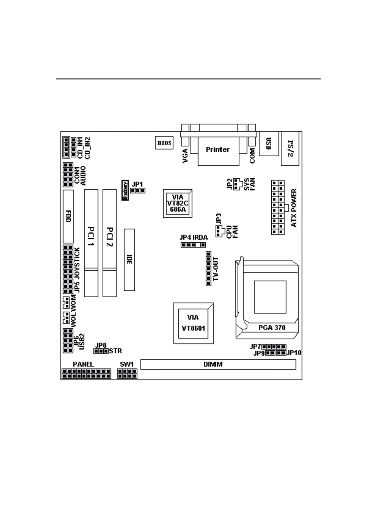
Motherboard Layout
1-3
Page 9

Jumpers
1. JP1 Clear CMOS
2. JP7, JP9¢JP10 Select CPU FSB
3. SW1 CPU Overclock Frequency
4. JP8 Select STR function
Expansion Slots
1. DIMM Support 168-pin DIMM Memory
PCI 1 to PCI 2 32-bit PCI Bus Expansion slot
2.
Connectors
1. PS/2 Connector PS/2 Keyboard &Mouse Connector
2. Floppy Floppy Drive Connector
3. IDE 1 IDE Connector
4. Printer Printer (Parallel) Port Connector
5. JP2 System Fan Connector
6. JP3 CPU Fan Connector
7. JP4 IrDA Connector
8. JP5 Joystick pinheader
9. JP6 Universal Serial Bus pinheader
10.CON 1 Audio pinheader
11.CD_IN Audio CD_IN1 and CD_IN2 Connector
12.TV-OUT(optional) TV-OUT pinheader
12. ATX Power ATX Power Connector
13.WOM & WOL Modem & LAN Wake Up Connector
14. Panel
- PWR LED ATX Power LED (3pins)
- SPEAKER Chassis Speaker (4pins)
- HDD LED HDD LED (2pins)
- RESET Reset Switch (2pins)
- PWR ON ATX Power Switch (2pins)
Overview
1-4
Page 10

Chapter 2
Hardware Installation
This chapter gives you a step-by-step procedure on how to install your system and
set jumper. The motherboard has several user-adjustable jumpers on the board that
allow you to configure your system to suit your requirements.
Cautions!! P rotecting Against Electrostatic Discharge
Static electricity can harm delicate components inside your system. To prevent
static electricity damage, discharge static electricity from your body before you
touch any ofyour motherboard electronic components, such as the microprocessor. Observe the following precautions:
- Do not removes the motherboard from its anti-static packaging until you are
ready to install it into a computer case.
- Before you handle the motherboard in any way, touch a grounded, antistatic
surface, such as an unpainted portion of the system chassis, for a few seconds
to discharge any built-up static electricity.
- Handle add-in cards and modules by the edges or mounting bracket.
2-1
Page 11
Hardware Installation
Set Jumpers:Set Jumpers:
Set Jumpers:
Set Jumpers:Set Jumpers:
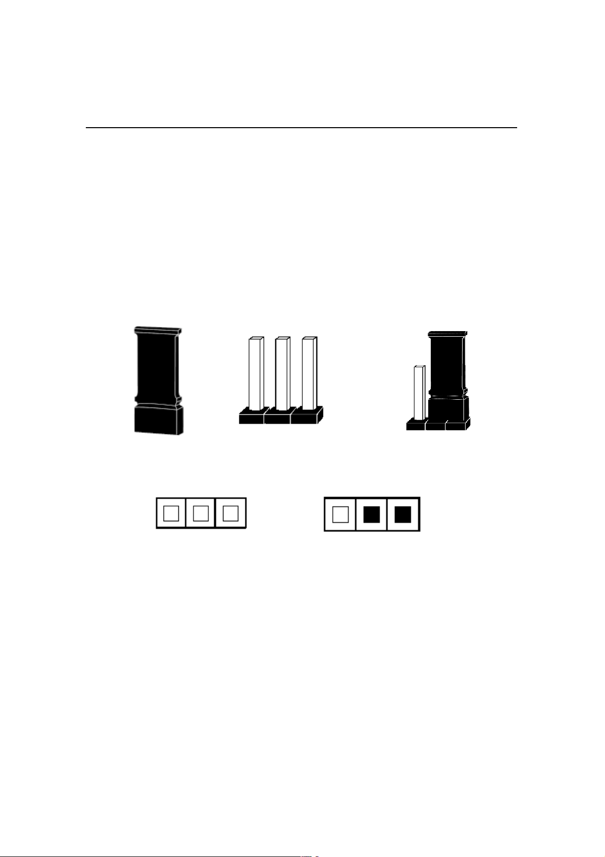
Jumpers are used to select the operation modes for your system. Each jumper on the
board has several metal pins with each pin representing a different function. A “1”
is written besides pin 1 on jumpers with several pins. To set a jumper, a plastic cap
containing metal contactor is placed over the jumper pins according to the required
configuration. A jumper is said to be shorted when the plastic cap has been placed
on two pins of it.The types of jumpers used in this manual are shown below:
Jumper Cap
Open set
3-pin Jumper
3
Short set
1
2
Note:
Users are not encouraged to change the jumper settings not listed in this manual.
Changing the jumper settings improperly may adversely affect system performance.
2-2
Page 12
Hardware Installation
Install CPUInstall CPU
Install CPU
Install CPUInstall CPU
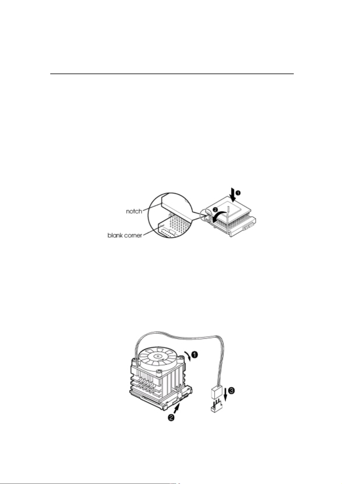
The CPU module resides in the socket 370 on the motherboard.Please following the
steps introduced below to complete the CPU installation.
1) Locate the new processor you are installing over the socket so that the notched
corner on the processor (pin 1) can be aligned with the blank corner on the
socket. Then gently push the processor straight into the socket until its pins
are completely inserted into the holes of the socket.
Caution:
If you install the processor chip in the wrong orientation, you may burn the
chip and void your warranty. So you should install it careful deeply.
2) Press the ZIF handle back to close it.
3) Attach the heat sink to the processor socket and then connect a fan connector
cable from the CPU fan to the CPU fan connector.
2-3
Page 13
Hardware Installation
CPU Jumper Setting
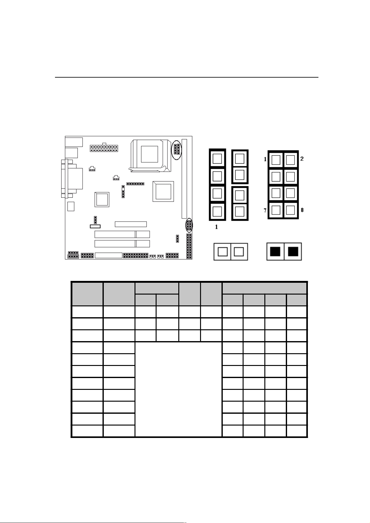
After installing the CPU, you must set the clock selection jumpers to match the fre-
¢¢
JP7
quency of the CPU. Find the jumpers labeled
jumpers according to the figure below and table for CPU FSB and CPU overclock
frequency. We recommend them to users.
¢JP9
¢¢
¢¢
¢JP10
¢¢
and SW1 set the
Caution !!
We don’t recommend user to try overclock, it may damage your CPU and
result in a slower speed. Please think carefully before you use overclock
function.
We introduce you how to clear CMOS, and enter into system BIOS, it could help
you accomplish CPU setting in BIOS easyly.
Clear CMOS: JP1Clear CMOS: JP1
Clear CMOS: JP1
Clear CMOS: JP1Clear CMOS: JP1
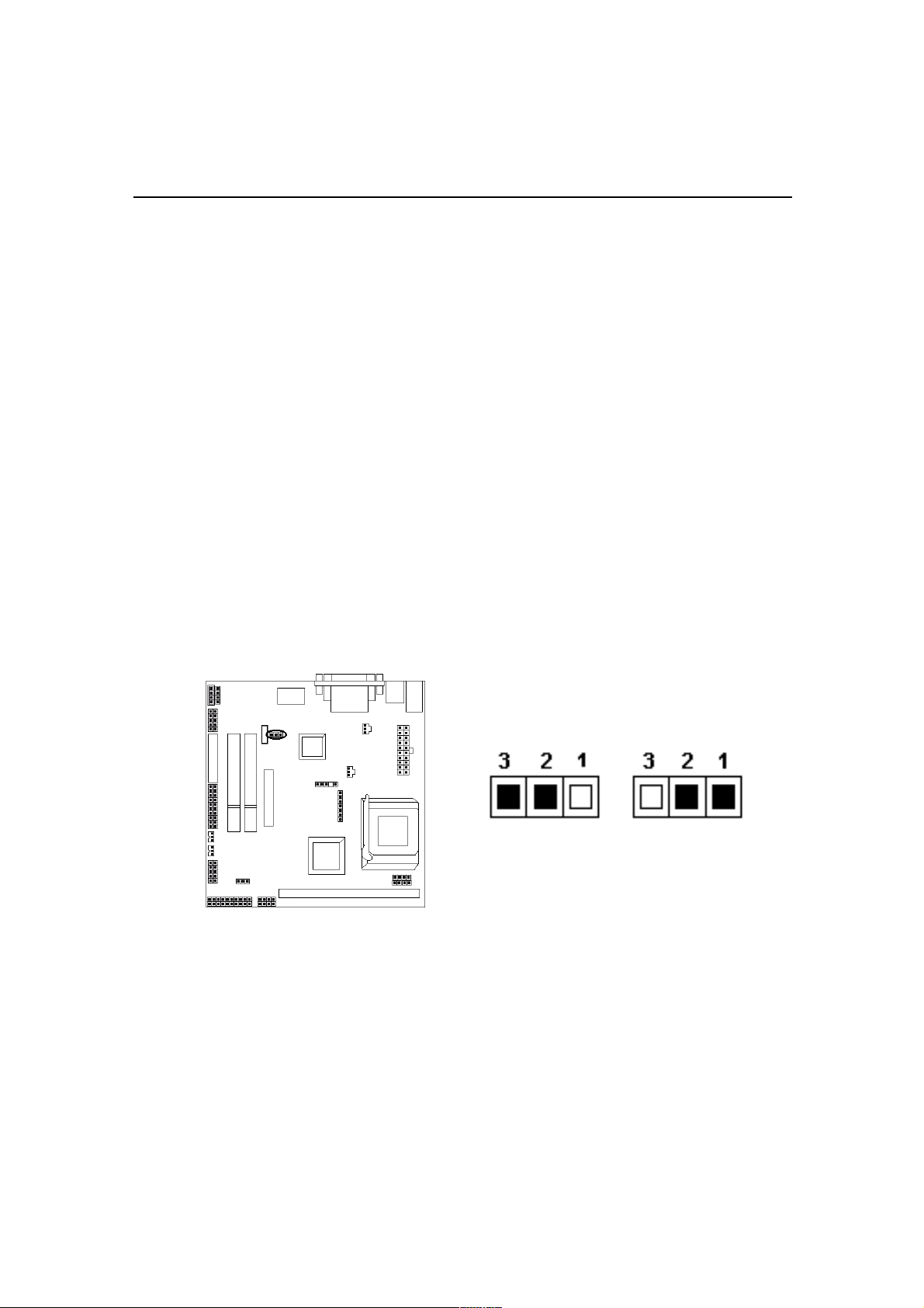
JP1 Clear CMOS
Clear CMOS
To Clear CMOS, please follow the steps below:
1. Power off the system and unplug the chassis AC power cord.
2. Short JP1 at pin 2-3 for few seconds.
3. Set JP1 back to its Normal position at pin1-2
4. Plug the AC power cord to the chassis.
5. Power on the system and load the BIOS set up default.
Normal
(Default)
2-4
Page 14
Hardware Installation
CPU Clock setting: JP7, JP9, JP10CPU Clock setting: JP7, JP9, JP10
CPU Clock setting: JP7, JP9, JP10
CPU Clock setting: JP7, JP9, JP10CPU Clock setting: JP7, JP9, JP10
Over Clock Setting: SW1Over Clock Setting: SW1
Over Clock Setting: SW1
Over Clock Setting: SW1Over Clock Setting: SW1
JP10
JP7
CPU
(MHz)
66 33 S S S S O O S S
100 33 S S O S O O O S
133 33 O O O O O O O O
75 37.5
83 41.6 S O S S
100 35 O O S S
110 36.6 S O S O
120 40 S S S O
124 41.3 S S S S
PCICL K
(MHz)
JP7
JP9 JP10
1-2 3-4
OPEN
JP9
OPEN (O)
SW1
(1-2) (3-4) (5-6) (7-8)
OS SS
SW1
SHORT (S)
2-5
140 35 S S O O
150 37.5 O S O O
Page 15
Hardware Installation
System Memory InstallationSystem Memory Installation
System Memory Installation
System Memory InstallationSystem Memory Installation
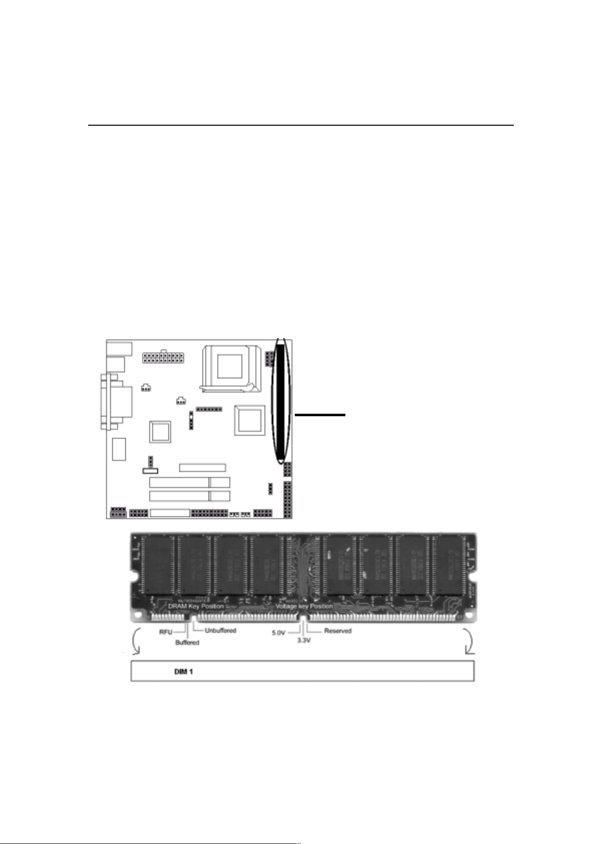
There are 1 piece 168-pin DIMM (Dual Inline Memory Module) sockets on the
motherboard which support SDRAM and EDO DRAM memory.
♦ To ensure reliability, it is recommended to use PC 100 SDRAM or PC 133
SDRAM for your high clock SDRAM performance requirement.
♦ If you are using low clock SDRAMs, you should set the SDRAM clock
option of the BIOS’s Chipset Feature Setup to HCLK-33 to ensure stability.
♦ DIMM Sizes support: 8MB, 16MB, 32MB, 64MB, 128MB, 256MB.
There is 1x168-pin DIMM slots
(DIMM1) that allow you to install
the system memory max up to 256 MB
SDRAM.
2-6
Page 16
Hardware Installation
1. Install DIMM
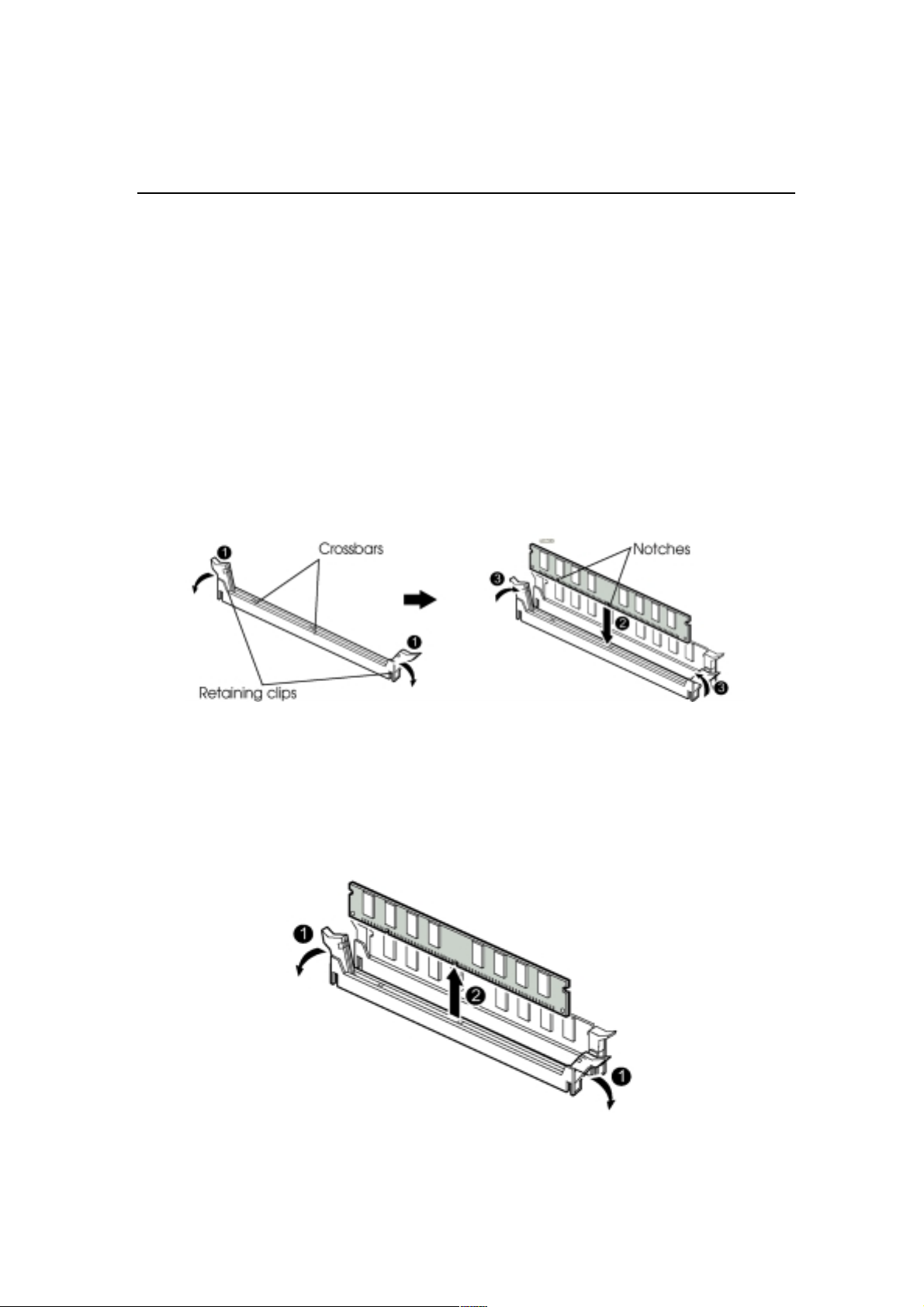
1) After remove the cover, install the DIMM in the sockets marked with
DIMM2, if the DIMM has been installed in the DIMM1 socket. Release the
plastic retaining clips at each end of the socket by pressing the clips outward
until they snap open.
2) Orient a DIMM to the socket so the two notches in the DIMM connector are
aligned with the crossbars in the socket.
3) Press the DIMM straight into the socket until the retaining clips snap into place
around the ends of the DIMM.
2 Removing a Memory Module
To remove memory modules, press the retaining clips outward simultaneously
until the DIMM disengages from the socket and then carefully remove the
DIMM from the socket.
2-7
Page 17
Hardware Installation
Install Expansion CardsInstall Expansion Cards
Install Expansion Cards
Install Expansion CardsInstall Expansion Cards
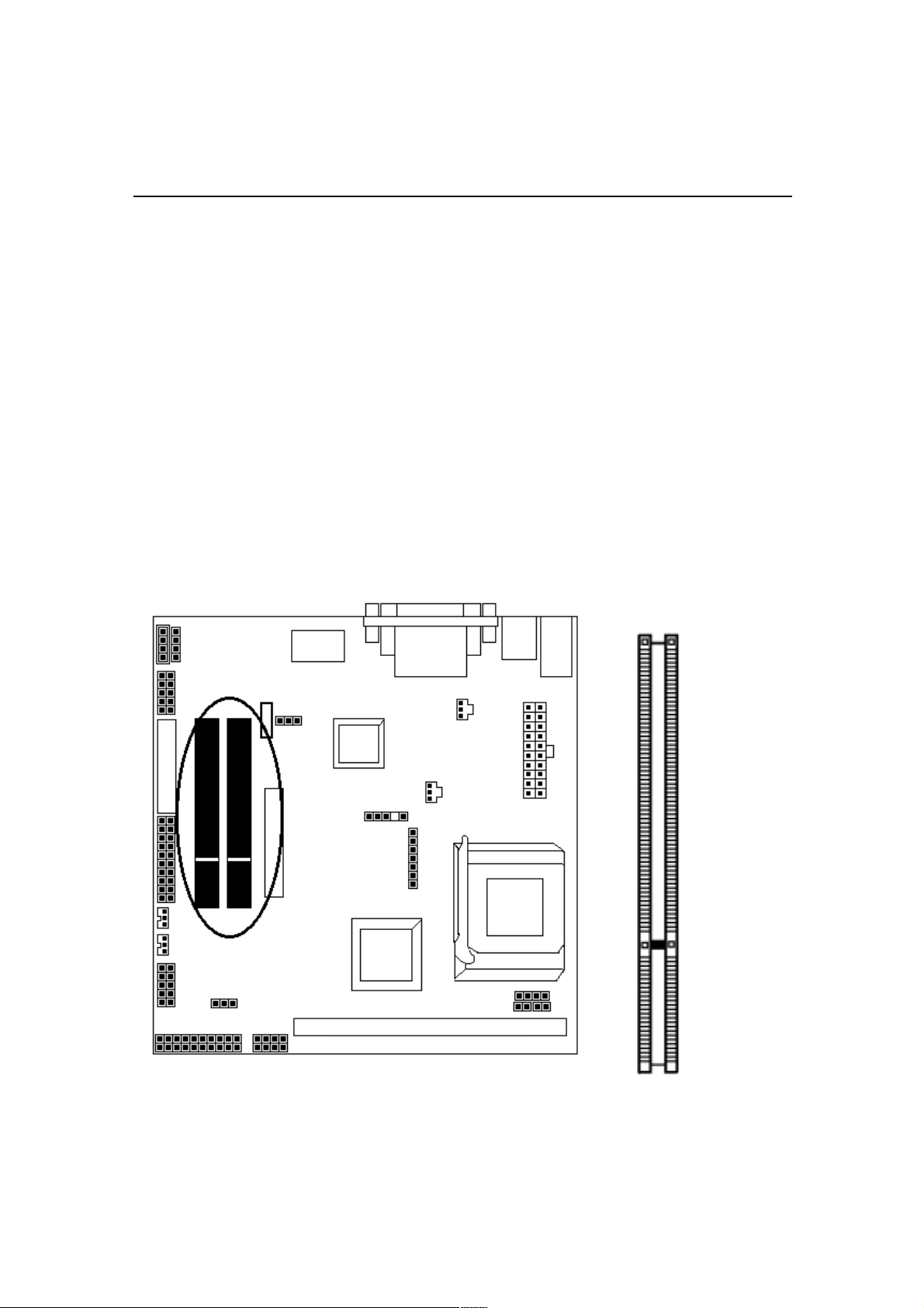
This section describes how to connect an expansion card to one of your system’s
expansion slots. Expansion cards are printed circuit boards that, when connected to
the mainboard, increase the capabilities of your system.VMZV7 only include
two PCI slots.
Caution:
Adjust any switches or jumpers on the expansion card, if necessary. When you
handle the card, be careful not to touch any components on the circuit board or the
gold-edged connector.
PCI Slot
2-8
Page 18
Hardware Installation
Connectors:Connectors:
Connectors:
Connectors:Connectors:
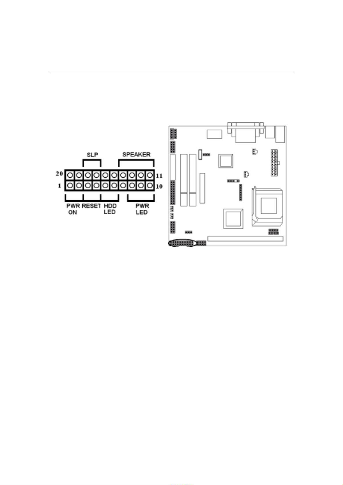
1. Pannel Connector
-PWR ON ATX Power Switch (2-pins)
-RESET Reset Switch (2-pins)
-HDD LED HDD LED (2-pins)
-POWER LED ATX Power LED (3-pins)
-SLP Sleep Function (2-pins)
-SPEAKER Chassis Speaker (4-pins)
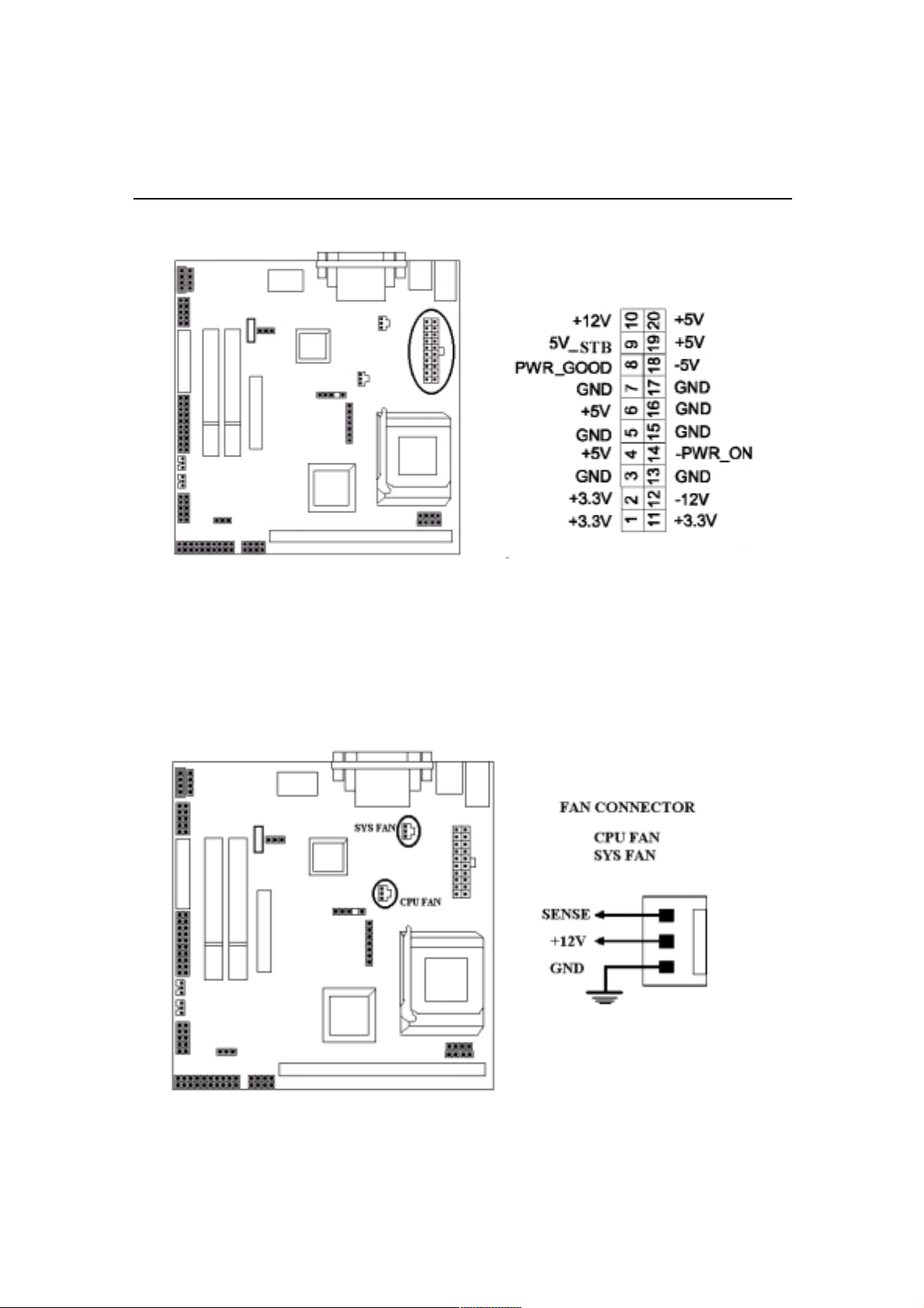
2. Power Connector
Connect the 20-pin ATX power supply cable to this power connector. Make sure
the right plug-in direction and the power supply is off before connecting or disconnecting the power cable.
2-9
Page 19
3. Fan Connector
Hardware Installation
Connect the CPU and System fan cables to the fan connectors shown below.
The fan connectors are marked as:
SYS FAN & CPU FAN on the motherboad.
2-10
Page 20
Hardware Installation
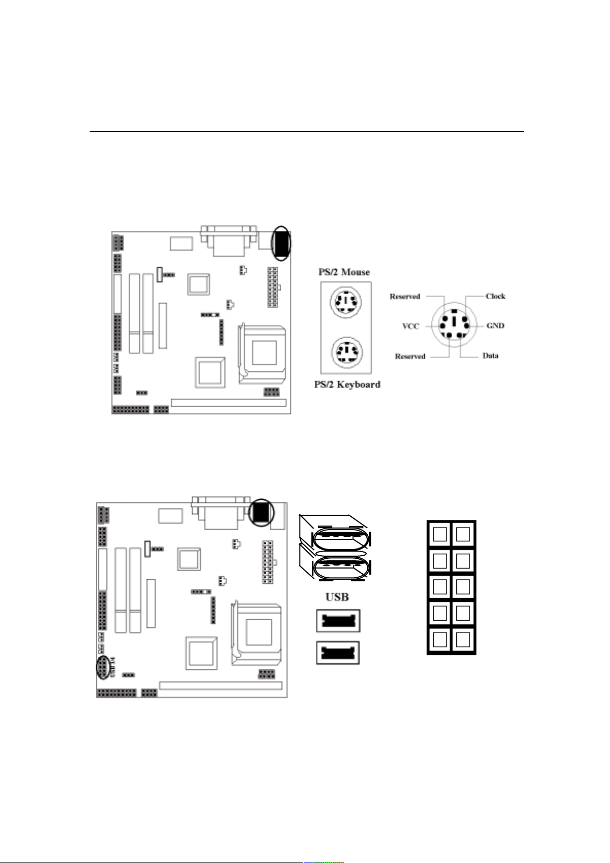
4. PS/2 Mouse and Keyboard Connectors
Connect the PS/2 Mouse and Keyboard to the onboard 6-pin Mini-Din connector
shown as below.
5. USB Connector: USB 3/4 JP6
Connect your USB device(s) to the onboard USB connector shown as below.
Top: USB1
Bottom: USB2
JP6
USB 3/4
2-11
Page 21
Hardware Installation
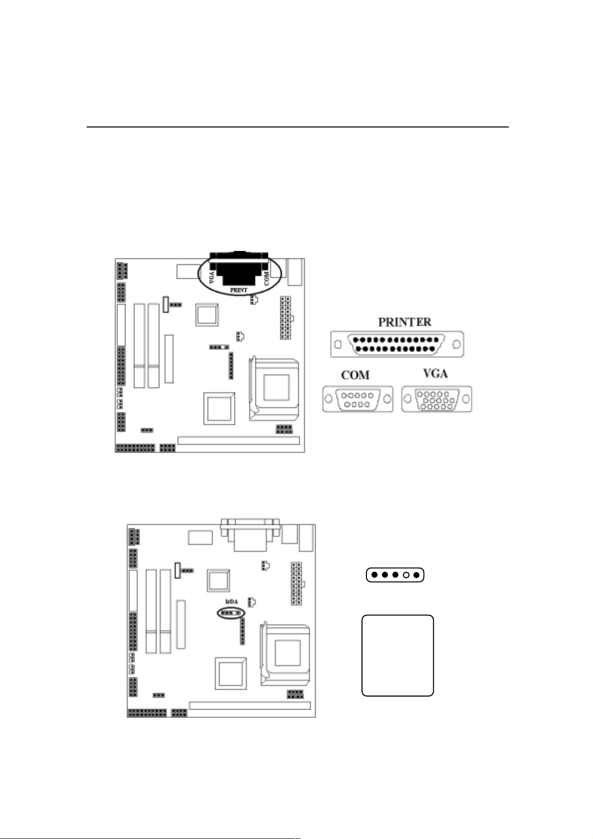
6. Serial Device COM, VGA and Printer Connectors
Connector your serial device(s) to the onboard serial connectors marked as
Connect the 15-pins VGA Monitor Output marked as
or other VGA compatible devices. Connect your local
VGA to your system monitor
Printer to the onboard
25-pin printer connector marked shown as below.
COM.
7. IrDA Connector: JP4
Connect your IR devices to the onboard IrDA connectors shown as below.
JP4 IrDA
5 4 3 2 1
Pin Description
1 +5V
2NC
3 IRRX
4 GND
5 IRTX
2-12
Page 22
Hardware Installation
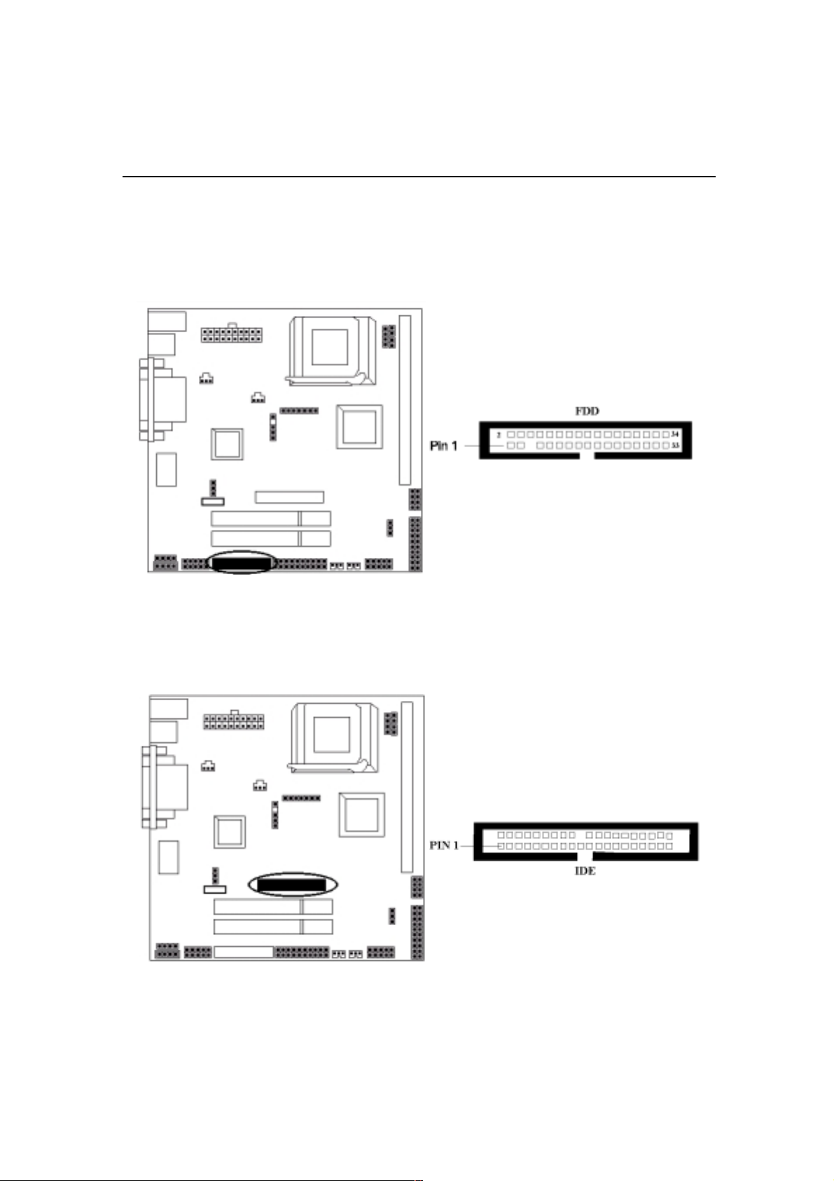
8. Floppy Drive Connector
Connect the floppy drive cable to the onboard 34-pin floppy drive connector marked
FDD.
as
9. IDE Hard Disk Connector
Connect your IDE devices to the onboard 40-pin IDE connectors marked as IDE.
2-13
Page 23
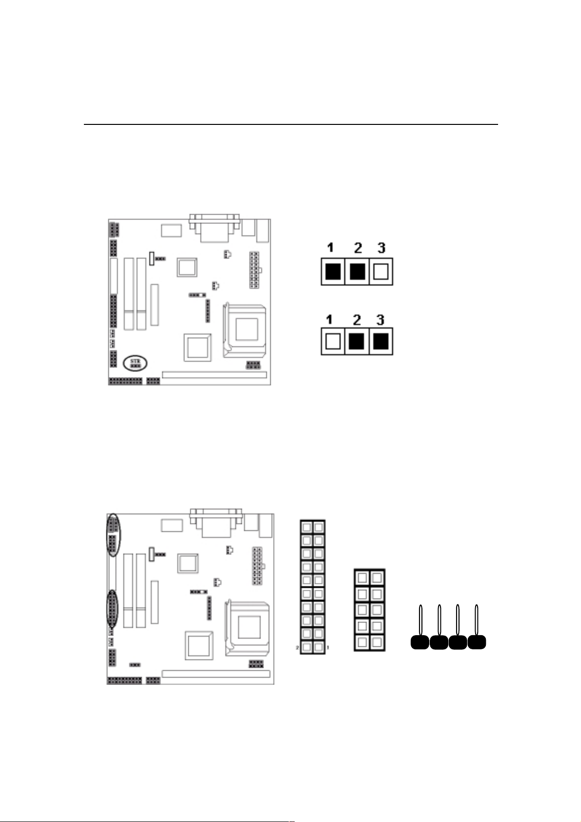
10. STR Pinheader
Hardware Installation
This pinheader
JP8 provides you to use Suspend To RAM (STR) function. Nor-
mally, you set jumper in “Default”.
JP8 STR Setting
Default
STR
11. Joystick / Audio & CD_IN pinheaders
The 10-pin Audio and the 20-pin JP5 Joystick pinheaders allow you to plug
audio and joystick conntector in. The CD connector onboard marked as
for CD-ROM connection.
JP1
JOYSTICK
AUDIO
CD-IN 1
CD_IN 2
CD-IN is
2-14
Page 24
Hardware Installation
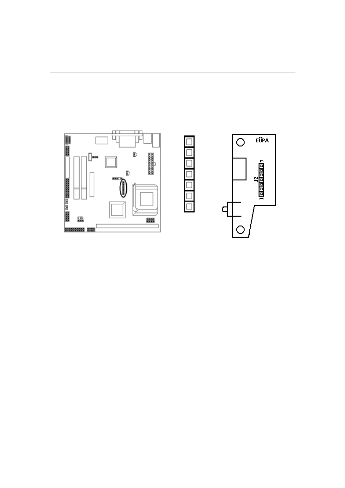
13. TV-OUT pinheaders(optional )
The 7-pin TV-OUT pinheader onboard allows you to connect TV connectors.
And we provide one EUPA TV bracket, showing as below:
TV-OU
Page 25

Chapter 3
CMOS Setup Utility
The rest of this manual is intended to guide you through the process of configuring
your system using Setup. While the BIOS is in control, the Setup program can be
activated by pressing the <Del>key during the POST (Power On Self-Test).If the
message disappears before you respond and you still wish to enter Setup, restart the
system to try again by turning it OFF then ON or pressing the “ RESET ” button on
the system case. You may also restart by simultaneously pressing <Ctrl>, <Alt>,
and <Delete> keys.
CMOS Setup Main MenuCMOS Setup Main Menu
CMOS Setup Main Menu
CMOS Setup Main MenuCMOS Setup Main Menu
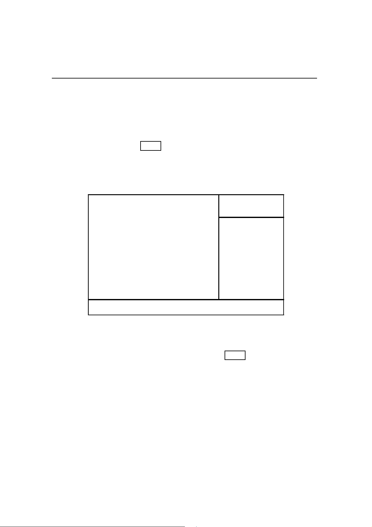
Once you enter the BIOS setup utility, the Main Menu will appear on the screen.
The Main Menu allows you to select from several setup functions . the arrow keys
to select among the items and press <Enter> to accept and enter the submenu.
CMOS Setup Utility - Copyright (C) 1984-2000 Award Software
!""Standard CMOS Features ! Frequency/Voltage Control
!""Advanced BIOS Features Load Fail-Safe Defaults
!""Advanced Chipset Features Load Optimized Defaults
!""Integrated Peripherals Set Supervisor Password
!""Power Management Setup
!""PnP / PCI Configuration
!""PC Health Status
Esc : Quit
F10 : Save & Exit Setup
Abandon all datas
Set User Passoword
Save & Exit Setup
Exit Without Saving
3-1
Page 26

CMOS Setup Utility
The main menu includes the following main setup categories, which defines basic
information about your system. Below are the keyboard function keys you can use
under the menu.
Menu function keys:
↑↑
↓↓
←←
↑
↓
←
↑↑
↓↓
←←
F1
F10
ENTER
ESC
: To Move around the screen. An item is highlighted if it is selected.
→→
→
→→
: Help.
: Save CMOS Changes & Exit.
: To select or enter a submenu.
: To quit the BIOS Setup Utility.
3-2
Page 27
CMOS Setup Utility
Standard CMOS SetupStandard CMOS Setup
Standard CMOS Setup
Standard CMOS SetupStandard CMOS Setup
The items in Standard CMOS Setup Menu are divided in 10 catagories. Each
catalogue includes one or more than one setup items. Use the keys to highlight
the item and then use the / <PgUp> / <PgDn> keys to select the value
↑ ↓ ← →
you want in each item.
CMOS Setup Utility - Copyright (C) 1984-2000 Award Software
Standard CMOS Features
Date (mm:dd:yy):
Time (hh:mm:ss):
!
IDE Primary M aster
!
IDE Primary Slave
Drive A
Drive B
Video
Halt On
Base Memory
Extended M emor y
Total Mem ory
Enter: Select F5 : Previous Values +/-/PU/PD: Value F10: Save
F6: Fail-safe defaults Esc:Exit F1: General Help F7 : Optimized Defaults
Tue, Aug
16:19:20
1.44M. 3.5in
None
EGA / VGA
All, But Keyboa rd
640K
65472K
1024K
29 2000
Item He lp
Menu Level
Chan ge the day, month, year
and ce ntury
!
Date & Time
To set the date and time, highlight the date area.Press /<PgUp>/ <PgDn>
↑ ↓ ← →
to set the current date. The date format is month: Jan. ~ Dec; date: 1 ~ 31; year:
1994 ~ 2079; hour: 00 ~ 23; and second: 00 ~ 59.
! Hard Disks → IDE Primary Master
! Hard Disks
→ IDE Primary Slave
3-3
Page 28

CMOS Setup Utility
Access Mode
Choose the access mode for this hard disk.
The optional are: Normal, LBA, Large, Auto (Default).
Capacity
Disk drive capacity (approximated). Note that this size is usually slightly greater
than the size of the formatted disk given by a disk checking program.
The optional are: Auto display your drive size.
Drive A / Drive B
Select the floppy drive type installed in your system. The available options for
Drive A and Drive B.
The optional are: 360K 5.25 in, 1.2M 5.25 in, 720K 3.5 in, 1.44M 3.5 in(Drive A
default), 2.88M 3.5 in and NONE (Drive B default).
Video
Select the video display card type installed in your system.
The optional are: EGA/VGA (Default), CGA 40, CGA 80 and Mono.
Halt On
This item defines the operation of the system POST (Power On Self-Test). You can
use this item to select which kind of errors will cause the system to halt during
POST.
The optional are: All Errors, No Errors, All But Keyboard (Default), All But
Diskette and All But Disk / Key
3-4
Page 29

Advanced BIOSFeaturesAdvanced BIOSFeatures
Advanced BIOSFeatures
Advanced BIOSFeaturesAdvanced BIOSFeatures
CMOS Setup Utility - Copyright (C) 1984-2000 Award Software
Advanced BIOS Features
CMOS Setup Utility
Virus Warning
Viru s W arn ing
CPU Internal Cache
External Cache
CPU L2 Cache EC C Check ing
Processor Nu mb er Feature
Quick Power On Self Test
First Boot Device
Second Boot Device
Third Boot device
Boot other device
Swap Floppy Drive
Boot Up Floppy Seek
Boot Up Numlock Status
Gate A20 Option
Typematic Rate Setting
* Typematic Rate ( Chars/Sec)
* Typematic Delay (Msec)
Security Option
OS Se lect Fo r D RA M > 64M B
Video BIOS shadow
C8000-CBFFF shadow
CC000-CFFFF shadow
D0000-D3FFF shadow
D4000-D7FFF shadow
D8000-DBFFF shadow
DC000-DFFFF shadow
Enter: Select F5 : Previous Values +/-/PU /PD: Value F1 0: Save
F6 : Fail-safe defaults Esc:Exit F1: General Help F7 : Optimized Defaults
Disabled
Enabled
Enabled
Enabled
Enabled
Disabled
Floppy
HDD-0
LS/ZIP
Enabled
Disabled
Enabled
On
Normal
Disabled
6
250
Setup
Non-OS2
Enabled
Disabled
Disabled
Disabled
Disabled
Disabled
Disabled
Menu Level
Allows you to choose the VIRUS
wa rning feat ure for IDE H ar d D isk
boot sector protection. I f this
function is enabled and someone
attempt to write data into this area,
BIOS will show a warning m essage
on screen a nd alarm beep.
Item Help
!
If this function enabled and someone attempt to write data into this area, BIOS will
automatically show a warming message on screen and alarm beep.
The optional are: Enabled, Disabled (Default)
CPU Internal / External cache
These two items controls Enable / Disable the CPU internal / external cache.
The optional are: Enabled (Default), Disabled
CPU L2 Cache ECC Checking
This item allows you to enable / disable CPU L2 Cache ECC Checking.
The optional are: Enabled (Default), Disabled
3-5
Page 30

CMOS Setup Utility
Processor Number Feature
This item allows you to enable / disable Processor Number.
The optional are: Enabled (Default), Disabled
Quick Power On Self Test
This item speeds up Power On Self Test (POST) after you power up the computer.
If it is set to Enable, BIOS will shorten or skip some check items during POST.
The optional are: Enabled, Disabled (Default)
First / Second / Third Boot Device
The BIOS attempts to load the operating system from the devices in the sequence
selected in these items.
The optional are: Floppy (First Default), HDD-0(Second Default), LS /ZIP
(Third Default), HDD-1/2/3, ZIP 100, SCSI, CDROM, LAN, Disabled.
Boot Other Device
Select your Boot Device Priority.
The optional are: Enabled (Default), Disabled
Swap Floppy Drive
If the system has two floppy drives, choose enable to assign physical drive B to
logical drive A and vice-versa.
The optional are: Enabled, Disabled (Default)
Boot Up Floppy Seek
Seeks disk drives during boot up.
The optional are: Enabled (Default), Disabled
Boot Up NumLock Status
Selects power on state for NumLock.
The optional are: Off, On (Default)
3-6
Page 31

CMOS Setup Utility
Gate A20 Option
Normal-a pin in the keyboard controller controls Gate A20.
Fast- lets chipset control Gate A20.
The optional are: Normal(Default), Fast
Typematic Rate Setting
Keystrokes repeat at a rate determined by the keyboard controller, when enabled,
the typematic rate and typematic delay can be selected.
The optional are: Enabled, Disabled(Default)
Typematic Rate (Chars/Sec)
Sets the number of times a second to repeat a key stroke when you hold the key
down.
The optional are: 6 (Default), 8, 10, 12, 15, 20, 24, 30
Typematic Delay (Msec)
Select the delay time after the key is held down before it begins to repeat the key
strokes.
The optional are: 250 (Default), 750, 1000
Security option
Select whether the password is required every time when you enter setup.
Setup -- The system will boot up.
System -- The system will not boot and access to setup will be denied if the correct
password is not entered at the prompt.
The optional are: Setup (Default), System
OS Select for DRAM > 64MB
Select OS2 only if you are running OS/2 operating system with greater than 64MB
of RAM on the system.
The optional are: Non-OS/2 (Default), OS/2
3-7
Page 32

CMOS Setup Utility
Video BIOS Shadow
This item defines if you leave default setting, video BIOS memory will be copied
from ROM into DRAM area to enhance system performance as DRAM access time
is faster than ROM
The optional are: Enabled (Default), Disabled
C8000-CBFFF to DC000-DFFFF Shadow
Set Enabled if you know the address that your add on card ROM used to shadow
them. If the item is Enabled, BIOS will copy the selected area from ROM to RAM
to increase system performance.
The optional are: SDRAM 10ns(De
Turbo
Advanced Chipset FeaturesAdvanced Chipset Features
Advanced Chipset Features
Advanced Chipset FeaturesAdvanced Chipset Features
.
fault), SDRAM 8ns, Normal, Medium, Fast,
This item allows you to configure the system based on the specific features
of the chipset. This chipset manages bus speed and access to system memory
recources, and external cache. It must be stated that these items should never
need to be altered.The default settings have been chosen because they provide
you the best operating conditions for your system. The only time you might
consider making any changes if you discovered that the datas were being lost
while control your system.
3-8
Page 33

CMOS Setup Utility
CMOS Setup Utility - Copyright (C) 1984-2000 Award Software
Advanced Chipset Features
Bank 0/1 DRAM Timing
SD RAM Cy c le Le ng th
DRAM Cl ock
Memor y Hole
P2C/C2P Concurrency
Fast R-W Turn Around
System BIOS Cacheable
Video RAM Cacheable
Frame Buffer Size
Onchip USB
USB Keyboard Support
Onchip Sound
CPU to PCI Write Buffer
PCI Dynamic Bursting
PCI Master 0 WS Write
PCI Delay Transaction
PCI#2 Access #1 Retry
Memory Parity / ECC Check
Enter: Select F5 : Previous Values +/-/PU/PD: Value F10: Save
F6 : Fail-safe defaults Esc:Exit F1: General Help F7 : Optimized Defaults
Bank 0/1 DRAM Timing
SDRAM 8/10ns
3
Host CLK
Disabled
Enabled
Disabled
Disabled
Disabled
8M
Enabled
Disabled
Enabled
Enabled
Disabled
Enabled
Disabled
Disabled
Disabled
Item Help
Menu Level
!
This item allows you to select the value in this field, depending on whether the
board has paged DRAMs or EDO (extended data output) DRAMs.
The optional are: SDRAM 8/10ns(Default), Normal, Medium, Fast, Turbo
SDRAM Cycle Length
When synchronous DRAM is installed, the number of clock cycles of CAS
latency depends on the DRAM timing. Do not reset this field from the default
value specified by the system designer.
The optional are: 3(Default), 2
3-9
Page 34

CMOS Setup Utility
DRAM Clock
This item allows you to control the DRAM speed.
The optional are: Host CLK(Default), Host-33M, Host+33M
Memory Hole
In order to improve performance, certain space in memory is reserved for ISA cards.
This memory must be mapped into the memory space below 16MB.
The optional are: 15M-16M, Disabled(Default)
P2C/C2P Concurrency
This allows you to enable/disable the PCI to CPU, CPU to PCI concurrency.
The optional are: Enabled(Default), Disabled
Fast R-W Turn Around
This item controls the DRAM timing. It allows you to enable/disable the fast read /
write turn around.
The optional are: Enabled, Disabled(Default)
System BIOS Cacheabled
Selecting Enabled allows caching of the system BIOS ROM at F0000h-FFFFFh,
resulting in better system performance. However, if any program writes to this
memory area, a system error may result
.
The optional are: Enabled, Disabled(Default)
Video RAM Cacheabled
Selecting Enabled allows caching of the Video RAM, resulting in better system
performance. However, if any program writes to this memory area, a system error
may result.
The optional are: Enabled, Disabled(Default)
3-10
Page 35

CMOS Setup Utility
Frame Buffer Size
Select the size of Frame Buffer
The optional are: 8M(Default), 4M, NA
On Chip USB
This should be enabled if your system has a USB installed on the system board and
you want to use it. Even when so equipped, if you add higher performance controller , you will need to disable this feature.
The optional are: Enabled (Default), Disabled
USB Keyboard Support
Select Enabled if your system contains a Universal Serial Bus Controller and you
have a USB keyboard.
The optional are: Disabled (Default), Enabled
Onchip Sound
This item allows you to control the onboard AC97 audio.
The optional are: Auto (Default), Disabled
CPU to PCI Write Buffer
When this field is Enabled, writes from the CPU to the PCI bus are buffered, to
compensate for the speed difference between the CPU to the PCI bus. When
Disabled, the writes are not buffered and the CPU must wait until the write is
complete before starting another write cycle.
The optional are: Enabled (Default), Disabled
3-11
Page 36

CMOS Setup Utility
PCI Dynamic Bursting
When Enabled, every write transaction goes to the write buffer. Burstable transactions then burst on the PCI bus and nonburstable transactions do not.
The optional are: Disabled (Default), Enabled
PCI Master 0 WS Write
When Enabled, writes to the PCI bus are executed with zero wait state.
The optional are: Enabled (Default), Disabled
PCI Delay Transaction
The chipset has an embedded 32-bit posted write buffer to support delay transactions
cycles. Select Enabled to support compliance with PCI specification version 2.1.
The optional are: Enabled, Disabled(Default)
PCI #2 Access #1 Retry
When disabled, PCI#2 will not be disconnected until access finishes (default).
When enable, PCI#2 will be disconnected if max retries are attempted without
success.
The optional are: Disabled (Default), Enabled
Memory Parity / ECC Check
E nable adds a parity check to the boot-up memory tests. Select Enabled only if the
system DRAM Contains parity.
The optional are: Disabled(Default), Enabled
3-12
Page 37

Integrated PeripheralsIntegrated Peripherals
Integrated Peripherals
Integrated PeripheralsIntegrated Peripherals
CMOS Setup Utility - Copyright (C) 1984-2000 Award Software
CMOS Setup Utility
Integrated Peripherals
OnChip IDE Channel 10
IDE Prefetch Mode
Primary Master PIO
Prima ry Slave PIO
Primary Master UDMA
Prima ry Slave UDMA
Init Display First
IDE HDD Block Mode
Onboard FDD Controller
Onboard Serial Port1
IR function Duplex
TX, RX inverting e nable
Onboard Parallel Port
Onboard Parallel Port Mode
ECP Mode Use DMA
Para llel Port EPP Type
Onboard Legacy Audio
Soun d Bla ster
SB I/O Base Address
SB IRQ Select
SB DMA Select
MPU-401
MPU-401 I/O Address
Game Port (200- 207)
Enter: Select F5 : Previous Values +/-/PU/PD: Value F10: Save
F6 : Fail-safe defaults Esc:Exit F1: General Help F7 : Optimized Defaults
Enabled
Enabled
Auto
Auto
Auto
Auto
PCI Slot
Enabled
Enabled
Auto
Half
No, Yes
378/ IRQ7
Normal
3
EPP1.9
Enabled
Disabled
220H
IRQ 5
DMA 1
Disabled
330-333 H
Enabled
Item H elp
Menu Level
!
On-Chip IDE Channel 0 / 1
The chipset contains a PCI IDE interface with support for two IDE channels. Select
Enabled to activate the primary IDE interface. Select Disabled to deactivate this
interface.
The optional are: Enabled (Default), Disabled
IDE Prefetch Mode
The onboard IDE drive interfaces supports IDE prefetching for faster drive accesses.
If you install a primary and/or secondary add-in IDE interface, set this field to
Disabled if the interface does not support prefetching.
The optional are: Enabled (Default), Disabled
3-13
Page 38

CMOS Setup Utility
Primary Master / Slave PIO
The two IDE PIO (Programmed Input/Output) fields let you set a PIO mode (0-4)
for each of the two IDE devices that the onboard IDE interface supports. Modes 0
through 4 provide successively increased performance. In Auto mode, the system
automatically determines the best mode for each device.
The optional are: Auto (Default), Mode 0, Mode 1, Mode 2, Mode3, Mode 4
Primary Master / Slave UDMA
Ultra DMA/66 implementation is possible only if your IDE hard drive supports it
and the operating environment includes a DMA driver (Windows 98 OSR2 or a
third-party IDE bus master driver). If your hard drive and your system software both
support Ultra DMA/66, select Auto to enable BIOS support.
The optional are: Auto(Default), Disabled
Init Display First
This item allows you to decide to active whether PCI Slot of VGA card or AGP first.
The optional are: PCI Slot (Default), AGP
IDE HDD Block Mode
Block mode is also called block transfer, multiple commands, or multiple sector
read/write. If your IDE hard drive supports block mode (most new drives do), select
Enabled for automatic detection of the optimal number of block read/writes persector the drive can support.
The optional are: Enabled (Default), Disabled
Onboard FDD Controller
Select Enabled if your system has a floppy disk controller (FDC) installed on the
system board and you want to use it. If you install add-in FDC or the system has no
floppy drive, select Disabled in this field.
The optional are: Enabled (Default), Disabled
3-14
Page 39

CMOS Setup Utility
Onboard Serial Port 1
Select an address and corresponding interrupt for the first and second serial ports.
The optional are: Auto (Default), Disabled, 3F8 / IRQ4, 2F8 / IRQ3, 3E8 / IRQ4,
2E8 / IRQ3
IR Function Duplex
This item allows you to select the IR half/full duplex function.
The optional are: Half (Default), Full
TX, RX
This item allow you to enable the TX, RX inverting which depends on different
H/W requirement. This field is not recommended to change its default setting for
avoiding any error in your system
The optional are: No & No, No & Yes(Default), Yes & No, Yes &Yes.
inverting enable
Onboard Parallel Port
Select a logical LPT port address and corresponding interrupt for the physical
parallel port.
The optional are: 378/IRQ7(Default), 278/IRQ5, 3BC/IRQ7, Disabled
Onboard Parallel Mode
Select an operating mode for the onboard parallel (printer) port. Select Normal,
Compatible, or SPP unless you are certain your hardware and software both support
one of the other available modes.
The optional are: Normal (Default), EPP, ECP, ECP/EPP
3-15
Page 40

CMOS Setup Utility
ECP Mode Use DMA
Select a DMA channel for the parallel port for use during ECP mode.
The optional are: 3 (Default), 1
Parallel Port EPP Type
Select EPP port type 1.7 or 1.9.
The optional are: EPP 1.9(Default), EPP 1.7
Onboard Legacy Audio
This field controls the onboard legacy audio.
# Sound Blaster : Disabled(Default)
# SB I/O Base Address : 220H(Default)
# SB IRQ Select : IRQ 5(Default)
# SB DMA Select : DMA 1(Default)
# MPU-401 : Disabled(Default)
# MPU-401 I/O Address : 330-333H(Default)
# Game Port (200-207H) : Enabled(Default)
3-16
Page 41

CMOS Setup Utility
Power Management SetupPower Management Setup
Power Management Setup
Power Management SetupPower Management Setup
The Power Management Setup allows you to configure your system effectively save
energy while operating in a manner consistent with your own style of computer use.
CMOS Setup Utility - Copyright (C) 1984-2000 Award Software
Power Management Setup
ACPI function
> Power Managemen
ACPI Suspend Type
PM Control by APM
Vid e o Of f Op ti on
Video Off Method
MODEM Use IRQ
Soft-Off by PWR-BTTN
> Wake up event
Enter: Select F5 : Previous Values +/-/PU/PD: Value F10: Save
F6 : Fail-safe defaults Esc:Exit F1: General Help F7 : Optimized Defaults
Enabled
Press Enter
S1(POS)
Yes
Suspen -- Off
V/H SYNC+ Blank
3
Delay 4 Sec
Press Enter
Menu Level
Item Help
!
ACPI Function
This item allows you to enable/disable the Advanced Configuration and Power
Management (ACPI).
The optional are: Enabled(Default), Disabled
Power Management
CMOS Setup Utility - Copyright (C) 1984-2000 Award Software
Power Management
Pow er Manage m e nt
HDD Power Down
Doze Mode
Sus pen d M ode
Enter: Select F5 : Previous Values +/-/PU/PD: Value F10: Save
F6 : Fail-safe defaults Esc:Exit F1: General Help F7 : Optimized Defaults
User Define
Disabled
Disabled
Disabled
Item Help
Menu Level
!
3-17
Page 42

CMOS Setup Utility
There are four selections for Power Management, three of which have fixed mode
settings.
Minimum power ma nagement. D oze Mode = 1 hr. Standby
Min. Power Saving
Max. Power Saving
User Defined
This category allows you to select the type (or degree) of power saving and is
directly related to the following modes:
1. HDD Power Down
2. Doze Mode
3. Suspend Mode
Mode = 1 hr., Suspend Mode = 1 hr., and HDD Power Down
= 15 m in.
Maximum power mana geme nt ONLY AVAILABLE FOR SL
CPU'S. D oze Mode = 1 min., Standby Mode = 1 min.,
Suspend Mode = 1 min., and HDD Power Down = 1 min.
Allows you to set each m ode individually. Whe n not disabled,
each of the ranges are from 1 min. to 1 hr. except for HDD
Power Down which ranges from 1 min. to 15 m in. and disable.
HDD Power Down
When enabled and after the set time of system inactivity, the hard disk drive
will be powered down while all other devices remain active.
The optional are: Disable (Default), 1 Min--15 Min
Doze Mode
When enabled and after the set time of system inactivity, the CPU clock will
run at slower speed while all other devices still operate at full speed.
The optional are: Disable(Default), 1Min, 2Min, 4Min, 6Min, 8Min, 10Min,
20Min, 30Min, 40Min, 1Hour
Suspend Mode
When enabled and after the set time of system inactivity, all devices except the CPU
will be shut off.
The optional are: Disable(Default), 1Min, 2Min, 4Min, 6Min, 8Min, 10Min,
20Min, 30Min, 40Min, 1Hour
3-18
Page 43

CMOS Setup Utility
This item lets you select a method of ACPI suspend.
The optional are: S1(POS) (Default), S3(STR)
PM Control by APM
When enabled, an Advanced Power Management device will be activated to
enhance the Max. Power Saving mode and stop the CPU internal clock. If Advance Power Management (APM) is installed on your system, selecting Yes gives
better power savings.
The optional are: No, Yes(Default)
Video Off Option
When enabled, this feature allows the VGA adapter to operate in a power saving
mode.
Always On Monitor will remain on during power saving modes.
Suspend
All Modes--
--
Off Monitor blanked when the systems enters the Suspend mode.
Monitor blanked when the system enters any power saving
Off
mode.
The optional are: Always On, Suspend --off (Default), All Modes -- off
Video Off Method
This determines the manner in which the monitor is blanked.
This selection will cause the system to turn off the vertical and
V/H SYNC+Blank
Blank Screen This option only writes blanks to the video buffer.
DPMS Support
horizontal synchronization ports and write blanks to the video
buffer.
Select this option if your monitor supports the Display Power
Management Signaling (DPMS) standard of the Video
Electronics Standards to select video power management values.
The optional are: V/H SYNC + Blank (Default), Blank Screen, DPMS Support
3-19
Page 44

CMOS Setup Utility
MODEM User IRQ
This determines the IRQ in which the MODEM can use.
The optional are: NA, 3(Default), 4, 5, 7, 9, 10, 11
Soft-Off by PWRBTN
Pressing the power button for more than 4 seconds forces the system to enter the
Soft-Off state when the system has “hung.”.
The optional are: Delay 4 sec, Instant-Off (Default)
Wake Up Events(PM events)
PM events are I/O events whose occurrence can prevent the system from entering a
power saving mode or can awaken the system from such a mode. In effect, the
system remains alert for anything which occurs to a device which is configured as
On, even when the system is in a power down mode.
CMOS Setup Utility - Copyright (C) 1984-2000 Award Software
Wake Up Events
VGA
LPT & CO M
HDD & FDD
PCI Master
Modem Ring Resume
RTC Alarm Resume
* Date (Of Month)
* Resume Time (hh:mm:ss)
IRQs Activity Monitoring
Enter: Select F5 : Previous Values +/-/PU/PD: Value F10: Save
F6 : F ail-safe def aults E sc:Exit F 1: Gen eral Help F7 : O ptim ized Def aults
Off
LPT /CO M
On
Off
Disabled
Disabled
0
0 4 11
Press Enter
Menu Level
VGA
When On, you can set the VGA awakens the system.
The optional are: Off (Default), On
Item H elp
!
3-20
Page 45

CMOS Setup Utility
LPT & COM
When On of LPT & COM, any activity from one of the listed system peripheral
devices or IRQs wakes up the system.
The optional are: NONE, LPT, COM, LPT/COM (Default)
HDD & FDD
When On of HDD & FDD, any activity from one of the listed system peripheral
devices wakes up the system.
The optional are: On(Default), Off
PCI Master
When On of PCI Master, any activity from one of the listed system peripheral
devices wakes up the system.
The optional are: Off(Default), On
Modem Ring Resume
An input signal on the serial Ring Indicator (RI) line (in other words, an incoming
call on the modem) awakens the system from a soft off state.
The optional are: Enabled, Disabled(Default)
RTC Alarm Resume
When Enabled, you can set the date and time at which the RTC (real-time clock)
alarm awakens the system from Suspend mode.
The optional are: Enabled, Disabled(Default)
3-21
Page 46

CMOS Setup Utility
IRQs Activity Monitoring
The following is a list of IRQ’s, interrupt ReQuests, which can be exempted much as
the COM ports and LPT ports above can. When an I/O device wants to gain the
attention of the operating system, it signals this by causing an IRQ to occur. When
the operating system is ready to respond to the request, it interrupts itself and performs the service.
When set On, activity will neither prevent the system from going into a power
management mode nor awaken it.
CMOS Setup Utility - Copyright (C) 1984-2000 Award Software
IRQs Activity Monitoring
Primary INTR
IRQ3 (COM2)
IRQ4 (COM1)
IRQ5 (LPT 2)
IRQ6 (Floppy disk)
IRQ7 (LPT 1)
IRQ8 (RTC Alarm)
IRQ9 (IRQ2 Redir)
IRQ10 (Reserved)
IRQ11 ( Reser ved)
IRQ12 (PS/2 Mouse)
IRQ13 (Coprocessor)
IRQ14 (Hard Disk)
IRQ15 (Reserved)
Enter: Select F5 : Previous Values +/-/PU/PD: Value F10: Save
F6 : Fail-safe defaults Esc:Exit F1: General Help F7 : Optimized Defaults
On
Enabled
Enabled
Enabled
Enabled
Enabled
Disabled
Disabled
Disabled
Disabled
Enabled
Disabled
Enabled
Disabled
Item Help
Menu Level
!
3-22
Page 47

CMOS Setup Utility
PnP / PCI ConfigurationsPnP / PCI Configurations
PnP / PCI Configurations
PnP / PCI ConfigurationsPnP / PCI Configurations
This section describes configuring the PCI bus system. PCI- Peripheral
Component Interconnect, is a system which allows I/O devices to operate at
speeds nearing the speed of CPU itself using when communicates with its
own special components.This section covers some very technical items and
it is strongly recommended that only experienced users should make any
changes to the default settings.
CMOS Setup Utility - Copyright (C) 1984-2000 Award Software
PnP / PCI Configuration
PNP OS Installed
Reset Configuration Data
Recources Controlled By
* IRQ Recources
* DMA Recources
PCI/VGA Palette Snoop
Assign IRQ For VGA
Assign IRQ For USB
Enter: Select F5 : Previous Values +/-/PU/PD: Value F10: Save
F6 : Fail-safe defaults Esc:Exit F1: General Help F7 : Optimized Defaults
No
Disabled
Auto(ESCD )
Press E nter
Press E nter
Disabled
Enabled
Enabled
Menu Level
Select Yes if you are using a
Plug and Play capable
operating system. Select No
if you need the BIOS to
configure non-boot devices
Item Help
!
PNP OS Installed
This item allows you to determine PnP OS is installed or not.
The optional: Yes, No (Default)
Reset Configuration Data
Normally, you leave this field Disabled. Select Enabled to reset Extended System
Configuration Data (ESCD) when you exit Setup if you have installed a new add-on
and the system reconfiguration has caused such a serious conflict that the operating
system cannot boot.
The optional are: Enabled, Disabled(Default)
3-23
Page 48

CMOS Setup Utility
Resources controlled By
The Award Plug and Play BIOS has the capacity to automatically configure
all of the boot and Plug and Play compatible devices. However, this
capability means absolutely nothing unless you are using a Plug and Play
operating system such as Windows98.
The optional are: Auto(ESCD) (Default), Manual
PCI/VGA Palette Snoop
Leave this field at Disabled.
The optional are: Enabled, Disabled(Default)
Assign IRQ For VGA & USB
Enable/Disable to assign IRQ for VGA & USB.
The optional are: Enabled(Default), Disabled
3-24
Page 49

CMOS Setup Utility
PC Health StatusPC Health Status
PC Health Status
PC Health StatusPC Health Status
This section helps you to get more information about your system including CPU
temperature, FAN speed and voltages. It is recommended that you contact with
your motherboard supplier to get proper value about your setting of the CPU
temperature.
CMOS Setup Utility - Copyright (C) 1984-2000 Award Software
PC Health Status
Current CPU Temp.
Current System Temp.
Vcore
2.5V
3.3V
5V
12V
Enter: Select F5 : Previous Values +/-/PU/PD: Value F10: Save
F6 : Fail-safe defaults Esc:Exit F1: General Help F7 : Optimized Defaults
Current CPU Temp.
Show you the current CPU temperature.
Current System Temp.
Show you the current system temperature.
Vcore
Show you the current system voltage.
Item Help
Menu L ev el
!
3-25
Page 50

CMOS Setup Utility
Frequency / VFrequency / V
Frequency / V
Frequency / VFrequency / V
CMOS Setup Utility - Copyright (C) 1984-2000 Award Software
oltage Controloltage Control
oltage Control
oltage Controloltage Control
Frequency / Voltage Control
Auto Detect DIMM / PCI Clk
Spread Spectrum.
CPU Host Clock (CPU / PCI)
Move Enter: Select F5 : Previous Values +/-/PU/PD: Value F10: Save
F6 : Fail-safe defaults Esc:Exit F1: General Help F7 : Optimized Defaults
Enab led
Disabled
Default
Menu Level
Item Help
!
Auto Detect DIMM / PCI Clk
To reduce the occurrence of electromagneticinterference (EMI), the BIOS detects
the presence or absence of components in DIMM and PCI slots and turns off
system clock generator pulses to empty slots.
The optional are: Enabled(Default), Disabled
Spread Spectrum
when the system clock generator pulses, the extreme values of the pulse generate
excess EMI. Enabling pulse spectrum spread modulation changes the extreme
values from spikes to flat curves, thus reducing EMI. This benefit may in some
cases be out weighedby problemswith timing-critical devices, such as a clocksensitive SCSI device.
The optional are: Enabled, Disabled(Default)
CPU Host Clock (CPU/PCI)
Setup CPU Host Clock (CPU / PCI).
The optional are: Default(Default), 66/33, 75/37, 83/41, 100/33, 103/34, 1 12/37,
124/41, 133/33, 140/35, 150/37
Caution:
We don’t recommend user to try over clock, it may damage your
CPU and result in a slower speed. Please think carefully before you
use overclock function.
3-26
Page 51
CMOS Setup Utility
Load Fail-Safe DefaultsLoad Fail-Safe Defaults
Load Fail-Safe Defaults
Load Fail-Safe DefaultsLoad Fail-Safe Defaults
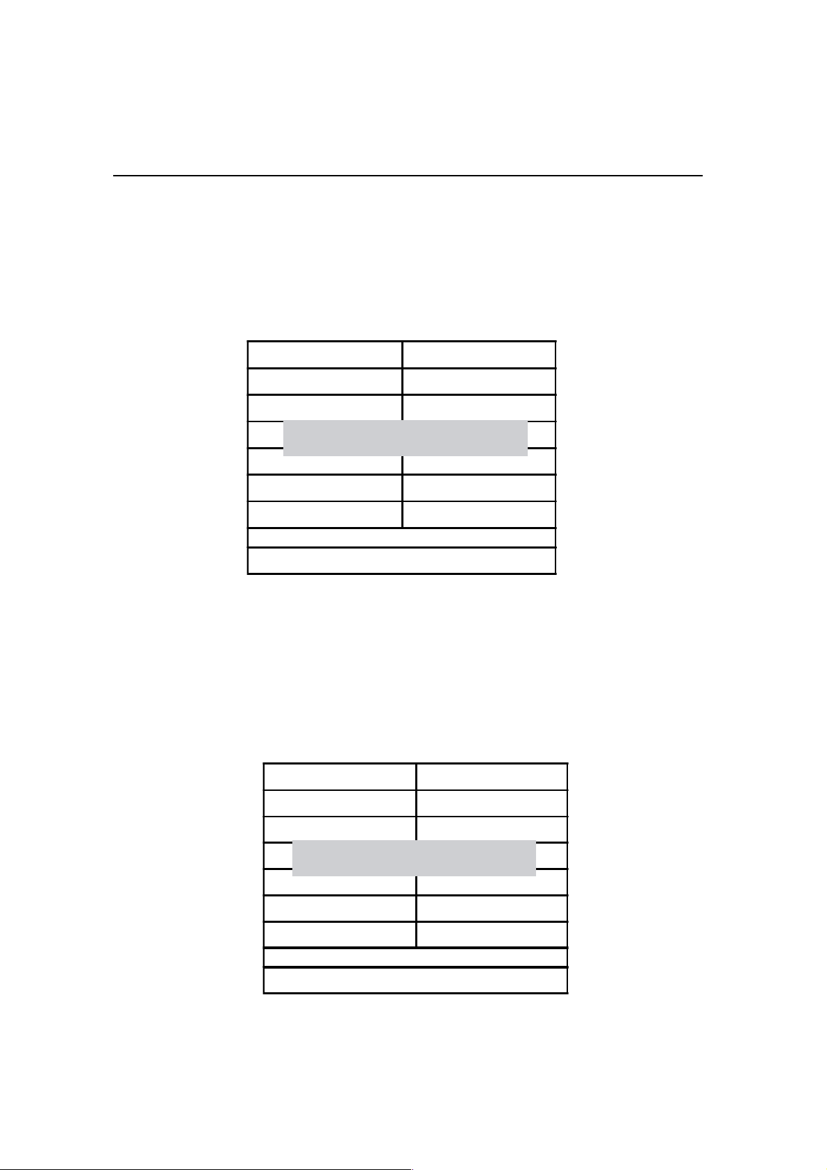
This option allows you load Fail-Safe Defaults settings. To load setup default,
press <Y> key to confirm the operation when you see the below display.
CMOS Setup Utility - Copyright (C) 1984-2000 Award Software
Standard CMOS Features
!""
Advanced BIOS Features Load Fail-Safe Defaults
!""
Advanced Chipset Features Load Optimized Defaults
!""
Integrated Peripherals Set Supervisor Passord
!""
!""
!""
!""
Esc : Quit F10 : Save & Exit Setup
Load Optimized DefaultsLoad Optimized Defaults
Load Optimized Defaults
Load Optimized DefaultsLoad Optimized Defaults
Load Fail - Safe Defaults (Y / N)? N
Power Management Setup Set User Passoword
PnP / PCI Configuration Save & Exit Setup
PC Health Status Exit Without Saving
Abandon all datas
Frequency / Voltage Control
!""
This option allows you load Optimized Defaults settings to optimize your
system. To load optimized default, press <Y> key to confirm the operation
when you see the below display.
CMOS Setup Utility - Copyright (C) 1984-2000 Award Software
your
!""
Standar d CMOS Fe atur es
!""
Advanced BIOS Features Load Fail-Safe Defaults
!""
Advanced Chipset Features Load Optimized Defaults
!""
Integrated Peripherals Set Supervisor Passord
Load Optimized Defaults (Y / N)?
!""
Power Management Setup Set User Passoword
!""
PnP / PCI Configuration
!""
PC Health Status Exit Without Saving
Esc : Quit F10 : Save & Exit Setup
Abandon all datas
!""
Frequency / Voltage Control
Save & Exit Setup
3-27
Page 52

CMOS Setup Utility
Set Supervisor / User PasswordSet Supervisor / User Password
Set Supervisor / User Password
Set Supervisor / User PasswordSet Supervisor / User Password
Password prevents unauthorized use of your computer. If you set a password, the
system prompts for the correct password before boot or access to setup. The main
difference between Supervisor Password and User Password is the privilege.
Because Supervisor Password allows you to modify all CMOS setup but User
password only some of them.
Their steps all as follows:
1. Highlight the item Set Supervisor Password / Set User Password on the main
menu and press ENTER.
2. The password dialog box will appear.
3. If you are installing a new password, carefully type in the password. Press
ENTER after you have typed in the password. If you are deleting a password
that is already installed just press ENTER when the password dialog box
appears.
4. The system will ask you to confirm the new password by asking you to type
it in a second time. Carefully type the password again and press ENTER, or
just press ENTER if you are deleting a password that is already installed.
5. If you typed the password correctly, the password will be installed.
[NOTE]
If you forget your password, or you want to cancel your password, you can do theIf you forget your password, or you want to cancel your password, you can do the
If you forget your password, or you want to cancel your password, you can do the
If you forget your password, or you want to cancel your password, you can do theIf you forget your password, or you want to cancel your password, you can do the
steps as the following:steps as the following:
steps as the following:
steps as the following:steps as the following:
(1) Password forgotten:
i. Turn off the system.
ii. Short JP1at Pin 2-3 for a few seconds to clear CMOS.
iii. Set the JP1 back to Pin 1-2.
iv. Power on the system.
(2) Clear Password:
Clear your password by key in the password you installed
before, then go to password setting to press ENTER twice.
3-28
Page 53

CMOS Setup Utility
Save & Exit SetupSave & Exit Setup
Save & Exit Setup
Save & Exit SetupSave & Exit Setup
Highlight this item and press ENTER to save the changes that you have
made in the setup utility and exit the setup program. When the Save and Exit
dialog box appears, press <Y> to save and exit, or press <N> to return to the
setup main menu.
Exit WExit W
Exit W
Exit WExit W
Use this option to exit setup utility without saving the CMOS value changes.
ithout Savingithout Saving
ithout Saving
ithout Savingithout Saving
3-29
Page 54
CMOS Setup Utility
How to Update YHow to Update Y
How to Update Y
How to Update YHow to Update Y
1. Create a bootable system floppy disk by typing [FORMAT A:/S] from the DOS
prompt without creating
2. Copy AWDFLASH.EXE to the just created boot disk.
3. Download an updated EUPA BIOS file from the Internet and save to the disk
you created earlier.(EUPA web site:
4. Boot from the disk you created earlier.
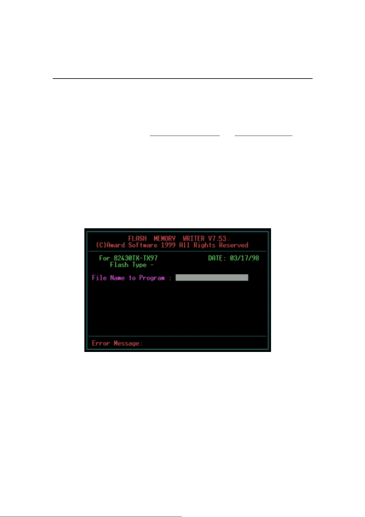
5. At the "A:\" prompt, type AWDFLASH and then press <Enter>. The screen
will displays the following window:
our Motherboard’our Motherboard’
our Motherboard’
our Motherboard’our Motherboard’
"AUTOEXEC.BAT" and "CONFIG.SYS" files.
www.eupacomputer.com)
s BIOS?s BIOS?
s BIOS?
s BIOS?s BIOS?
6. Type the new BIOS filename and the path, for example, A:\VXA.BIN and
then press <Enter>. Then prompt: Do you want to save BIOS?(Y/N) Press
<Y> to save current BIOS to file.Type the file name to save, then press
<Enter>.Prompt: Now backup system BIOS TO file!
3-30
Page 55

CMOS Setup Utility
7. After the backup,prompt: Are you sure to program?(Y/N) Press <Y> to start
to program the new BIOS information into the flash ROM. When the programming isfinished.You may press <F1> to reset the PC or <F10> to Exit
the AWDFLASH.
WARNING!!!
If you encounter problems while updating the new BIOS, DO NOT turn off
your system since this might prevent your system from booting up. Just repeat
the process, and if the problem still persists, update the original BIOS file you
saved to disk above. If the Flash Memory Writer utility was not able to
successfully update a complete BIOS file, your system may not be able to
boot up. If this happens, your system will need service.
NOTE!!!
The previous screen displays are provided as example only and may not
reflect the screen contents displayed on your system.
3-31
Page 56

Chapter 4
Software Utility
The support software for this motherboard is supplied in a CD. All the support programs are stored in separate folders, so you can find the program you need easily
enough. We recomend you to choose the program which you need most, it will assist
your computer system to high performance.
Note !!!Note !!!
Note !!!
Note !!!Note !!!
For update driver, please visit EUPA web site:
www.eupacomputer.com.
Installing Interface:Installing Interface:
Installing Interface:
Installing Interface:Installing Interface:
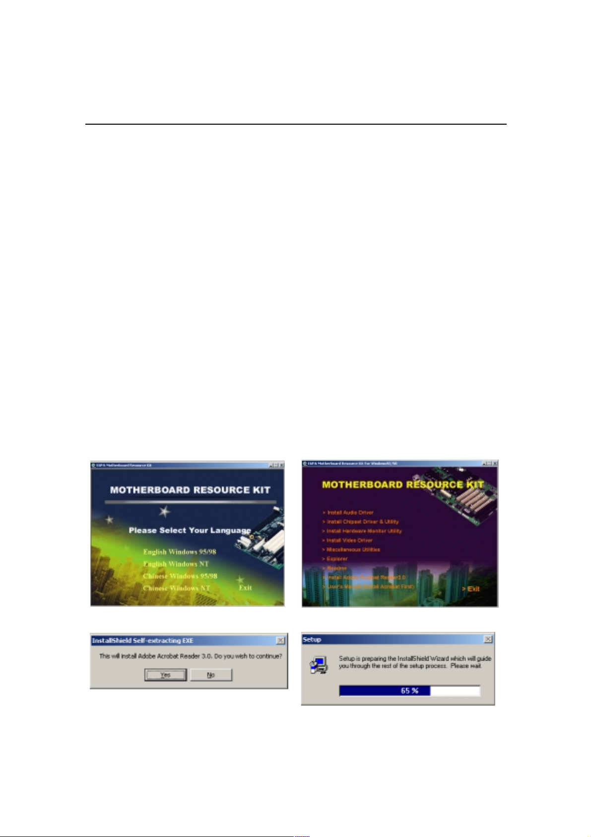
After you insert CD driver, it runs automaticly and appear the interface as below:
4-1
Page 57
Software Utility
Installing Driver Location:
To using software, you’d better find chipset driver location: IDE / VIA, then install
contents step by step.
VMZV7 integrates AC’97 audio system, providing perfect audio quality to users.
(AC’97 system is the very popular with audio system in the world. According to
the most of users’ requirement, we design the function in the motherboard to
increase system practicability.)
Also the product integrates audio codec function and video as well, to use the
function, we provides its location:
/video/via8601 /video/via8601
/video/via8601
/video/via8601 /video/via8601
/audio/via161/audio/via161
/audio/via161
/audio/via161/audio/via161
1/setup.exe1/setup.exe
1/setup.exe
1/setup.exe1/setup.exe
Installing ADOBE Acrobat Read Driver:
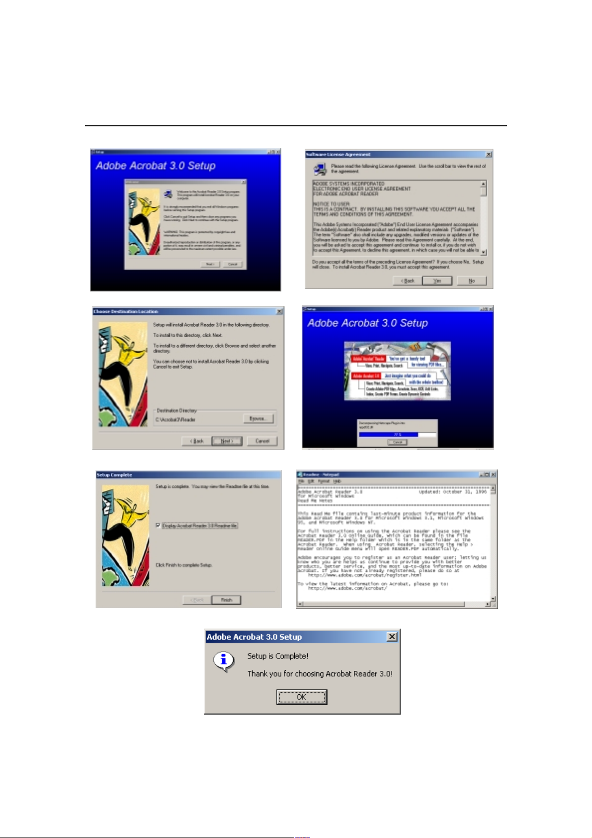
Insert CD Driver to the CD-ROM, driver runs by itself, and appear the following
interface, please refer to the procedure, then finish installing.
4-2
Page 58
Software Utility
4-3
Page 59

This Page Is Left For Note
 Loading...