

Page 1

ILA
Socket PGA370 Mainboard
User's Manual
Model : ILA
Manual version : English, version 1.0
Release Date : January 4, 1999
Page 2

Copyright
Copyright 1999 by this company. All rights reserved.
No part of this publication may be reproduced, transmitted, transcribed,
stored in a retrieval system, or translated into any language in any form or by
any means, electronic, mechanical, magnetic, optical, manual or otherwise,
without the prior written consent of the copyright holders.
User’s Notice
The contents of this publication are subject to change. This company reserves
the right to alter the contents of this publication at any time and without
notice. The contents of this publication may contain inaccuracies or
typographical errors and is supplied for informational use only.
Intel and Pentium are registered trademarks of Intel Corporation.
OS/2 and IBM are registered trademarks of International Business Machines.
Windows and MS-DOS are registered trademarks of Microsoft Corporation.
AWARD is a registered trademark of Award Software Inc.
Other brand, corporate, and product names may or may not be registered
trademarks or copyright of their respective companies.
II
Page 3

FCC & DOC Compliance
Federal Communications Commission Statement
This device complies with FCC Rules Part 15. Operation is subject to the
following two conditions:
² This device may not cause harmful interference, and
² This device must accept any interference received, including
interference that may cause undesired operation.
This equipment has been tested and found to comply with the limits for a
Class B digital device, pursuant to Part 15 of the FCC Rules. These limits are
designed to provide reasonable protection against harmful interference in a
residential installation. This equipment generates, uses and can radiate radio
frequency energy and, if not installed and used in accordance with the
manufacturer
communication. However, there is no guarantee that interference will not
occur in a particular installation. If this equipment does cause harmful
interference to radio or television reception, which can be determined by
turning the equipment off and on, the user is encouraged to try to correct the
interference by one or more of the following measures:
² Re-orient or relocate the receiving antenna.
² Increase the separation between the equipment and the receiver.
² Connect the equipment to an outlet on a circuit different from that to
which the receiver is connected.
² Consult the dealer or an experienced radio/TV technician for help.
Warning! The use of shielded cables for the connection of the monitor to
the graphics card is required to assure compliance with FCC regulations
Changes or modifications to this authority to operate this equipment.
III
Page 4

CONTENTS
SECTION 1: PRODUCT INFORMATION
1-1 Manual Features……………………………………………………..….…...1-1
1-2 Package Check List.................... …………………………1-1
1-3 Mainboard Specification...…….…………………………………1-2
1-4 Mainboard Layout ……………………………………………………………..1-6
SECTION 2: HARDWARE INSTALLATION
2-1 Jumper Settings.........................................2-1
2-1.1 CMOS Clear Setting ………..............………… … ………...2-1
2-1.2 CPU Type Setting …………………......................……..…..2-2
2-1.3 Power Supply Type ……………….......................……..…...2-2
IV
2-2 Connectors ……….……....…………….………………………………........2-3
2-2.1 Panel Connector……….…...………………………………..……………2-3
2-2.2 AT Power Connector………………………………....………………2-4
2-2.3 ATX Power Connector…………………………………..…………..2-4
2-2.4 Fan Connectors…….……..……………………………………….…………2-5
2-2.5 PS/2 Mouse Connector…………………………..……..…………2-5
2-2.6 Keyboard Connector….……………………………..…..……………2-6
2-2.7 Serial Device(COM1/COM2) Connectors….2-6
Page 5

2-2.8 Printer Connector.………………………………………………..…..2-7
2-2.9 Floppy Drive Connector…….….….……...................….…2-7
2-2.10 IDE Hard Disk and CD-ROM Connector..…….…….……2-8
2-2.11 IrDA Connector…….….………………………........………2-9
2-2.12 Wake On LAN Connector….….….……....…....……….…2-9
2-3 System Memory Installation .......……………...2-10
2-3.1 Type .............………………………….........….……….…2-10
2-3.2 Speed ..……….………………………………………….…2-10
2-3.3 Buffered and Non-buffered ..……..........….....….….……2-11
2-3.4 2-clock and 4-clock Signal….……..….…...………...……2-11
2-3.5 Parity and Non-parity………....……...………….......……2-11
2-3.6 Memory Auto detection by BIOS …....….…………….…2-11
2-3.7 Suggested SDRAM combination ….........…...……….…2-12
2-4 Game/Audio Connector……………………………………………2-12
SECTION 3: CMOS SETUP UTILITY
3-1 BIOS Setup Main Menu ..............................3-1
3-2 Standard CMOS Setup...............................3-2
3-3 BIOS Features Setup .................................3-5
3-4 Chipset Features Setup...........................3-10
3-5 Power Management Setup.......................3-15
3-6 PNP/PCI Configuration Setup .................3-21
3-7 Load Setup Defaults ................................3-25
3-8 Load Turbo Defaults................................3-26
3-9 Integrated Peripherals .............................3-27
V
Page 6

3-10 Password Setting………................…..………………..…3-32
3-11 IDE HDD Auto Detection…....….…..……………………….3-33
3-12 Save & Exit Setup………..........….….…………………………..3-33
3-13 Exit without Saving……..……......….……………………….….3-33
SECTION 4: BIOS/SOFTWARE UTILITY
4-1 Flash Utility Maxflash.exe..........................4-1
4-2 BIOS Flash/Upgrade Protection ......…….…....4-2
4-3 Remove Question Marks "?" in Win95
Device Manager……………………………………………………………….....4-2
4-4 Install Bus Master IDE (Ultra DMA/33)
Driver ………………………………......…………………………………………...…...4-3
VI
SECTION 5: AUDIO DRIVER/UTILITY
5-1 Windows 95/98 Driver Installation………….…..5-1
5-2 Windows NT Driver Installation…………………....5-4
5-3 DOS/Windows 3.1 Driver Installation…….…5-5
5-4 OS/2 Driver Installation………………………………………..….5-5
Page 7

SECTION 1.
PRODUCT INFORMATION
Thanks for purchasing ILA Socket PGA370 mainboard.
This user’s manual contains all the information and features that show you
how to use the ILA mainboard. Please take a moment to familiarize
yourself with the design and organization of this manual.
1-1 Manual Features
This manual is divided into the following four sections:
Section 1: Product Information
A brief overview of what comes in the mainboard package, the mainboard
layout and the specification it appears.
Section 2: Hardware Installation
Tell you the usage of the mainboard jumpers and the connectors.
Section 3: CMOS Setup Utility
A summary of the mainboard CMOS (BIOS) Setting.
Section 4: BIOS/Software Utility
Introduction of some useful mainboard’s BIOS/Software utility.
Section 5: Audio Driver/Utility
Install Audio Driver & Utility
ILA USER’S MANUAL 1-1
Page 8

I. PRODUCT INFORMATION
1-2 Package Check List
This ILA mainboard package contains the following items. Please inspect
the package contents and confirm that everything is there. If anything is
missing or damaged, call your vendor for instructions before operating.
The package includes:
l One ILA Mainboard
l One Floppy Interface Cable
l One IDE Interface Cable
l One Audio Interface Cable
l One CD Title including Bus Master IDE Driver and Utilities
l One User’s Manual
l One serial port bracket
l One parallel port & PS/2 Mouse bracket
1-3 Mainboard Specification
Form Factor
Board Size
CPU
System Memory
Chipset
System Bus/FSB
l AT form factor
l 220 mm x 220 mm
l Supports Socket PGA370 Celeron CPU up to
433MHz
l For LX mainboard, DIMM 168-pin x 3 , SDRAM
added maximum up to 384MB
l For EX mainboard, DIMM 168-pin x 2 , SDRAM
added maximum up to 256MB
l Supports 64M-bit SDRAM technology
l Intel 440LX/EX AGP Chipset
l 66MHz
l 68.5/75/83.3MHz (Available for over-clocking)
1-2 ILA USER’S MANUAL
Page 9
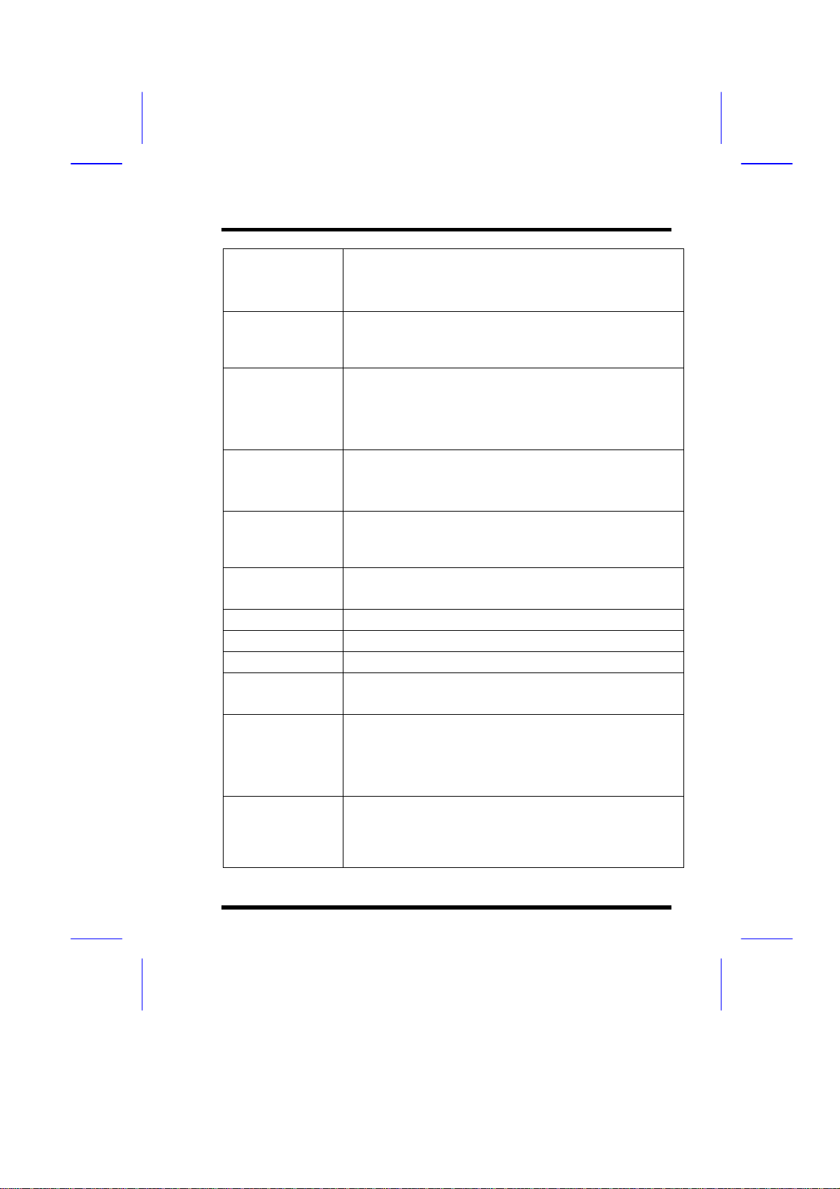
I. PRODUCT INFORMATION
Expansion Slots
Serial Port
Parallel Port
Floppy Interface
IDE Interface
USB Interface
PS/2 Mouse
Keyboard
Fuse
RTC and Battery
Wake Up Function /
Power On function
Synchronous
Switching Regulator
l 1 x AGP bus
l 2 x ISA bus
l 3 x PCI bus with Bus master/slave mode
l Two serial ports UART 16550 compatible
l Sets serial port 2 to operate in normal mode , IrDA or
ASKIR
One parallel port supports :
l SPP-standard parallel port
l EPP-enhanced parallel port
l ECP-extended capabilities port
Supports drives inches/format with:
l 3.5 inches—720KB/1.44MB/2.88MB
l 5.25 inches—360KB/1.2MB
l Dual PCI IDE interface support up to 4 x IDE HDD or
CDROM
l Supports PIO mode4 , DMA mode2 and Ultra DMA33
l Two USB ports supported
l USB legacy keyboard function supported
l PS/2 mouse supported
l AT keyboard supported
l Supports recoverable fuse for USB and KB/Mouse
l RTC build in chipset (south bridge PIIX4)
l Lithium (CR-2032) battery
l Modem ring wake up
l LAN wake up
l RTC Alarm wake up
l Keyboard/ PS/2 Mouse power on
l High efficient synchronous switching regulator for
CPU core voltage automatically detected
l Supports over-voltage / over-current protection
function
ILA USER’S MANUAL 13
Page 10
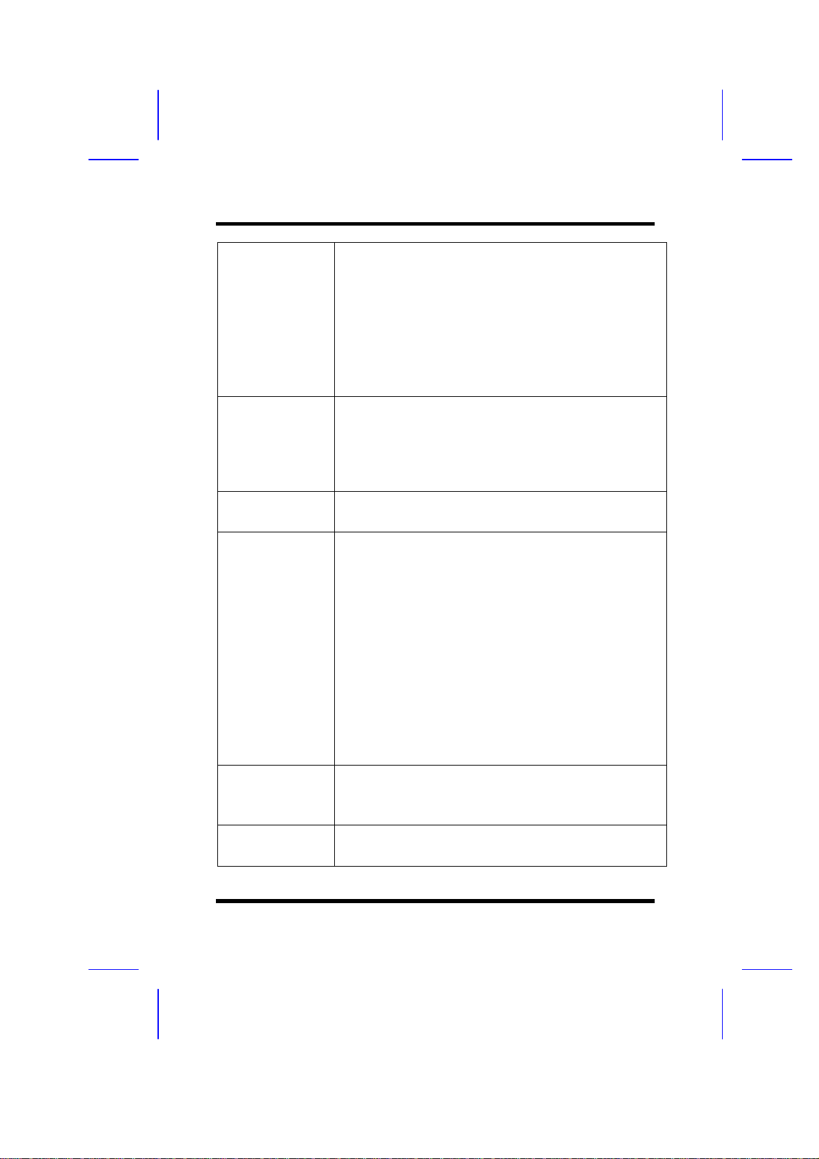
I. PRODUCT INFORMATION
Hardware Monitor
(Optional)
Sound Function
Power Function
BIOS
LED Indicator
Other
l Fan speed monitor—Two fan connectors , warning
when CPU or Housing fan is malfunction
l Fan speed control—Control CPU or Housing fan
speed for the thermal issue
l Voltage monitor—Warning when system voltage
(5V,12V,3.3V,VCORE) are abnormal
l CPU and system thermal monitor—Warning when
CPU and system temperature is higher than a
predefined value
l Integrated OPTi 82C933 sound controller compatible
with:
- Sound Blaster Pro
- Adlib
- Microsoft Windows System
l Supports ATX (20-pin) power connector
l Supports AT (12-pin) power connector
l Award BIOS
l Year 2000 Compliance
l PCI 2.1 Compliance
l PnP BIOS v1.0a Compliance
l APM v1.2 Compliance
l DMI 2.0 compliance
l Flash/Upgrade BIOS protection
l Supports ACPI (Advanced Configuration and Power
Interface) and OS Directed Power Management
l Supports SOFT power
l Anti-Virus Protection supported
l Floppy drive swapping function supported
l System power LED
l HDD activity LED
l System Suspend LED (Blanking)
l Auto-detect AT/ATX power supply type
l Support third Fan connector (2-pin)
1-4 ILA USER’S MANUAL
Page 11

I. PRODUCT INFORMATION
l Support CIR (Consumer IR) Function
ILA USER’S MANUAL 15
Page 12
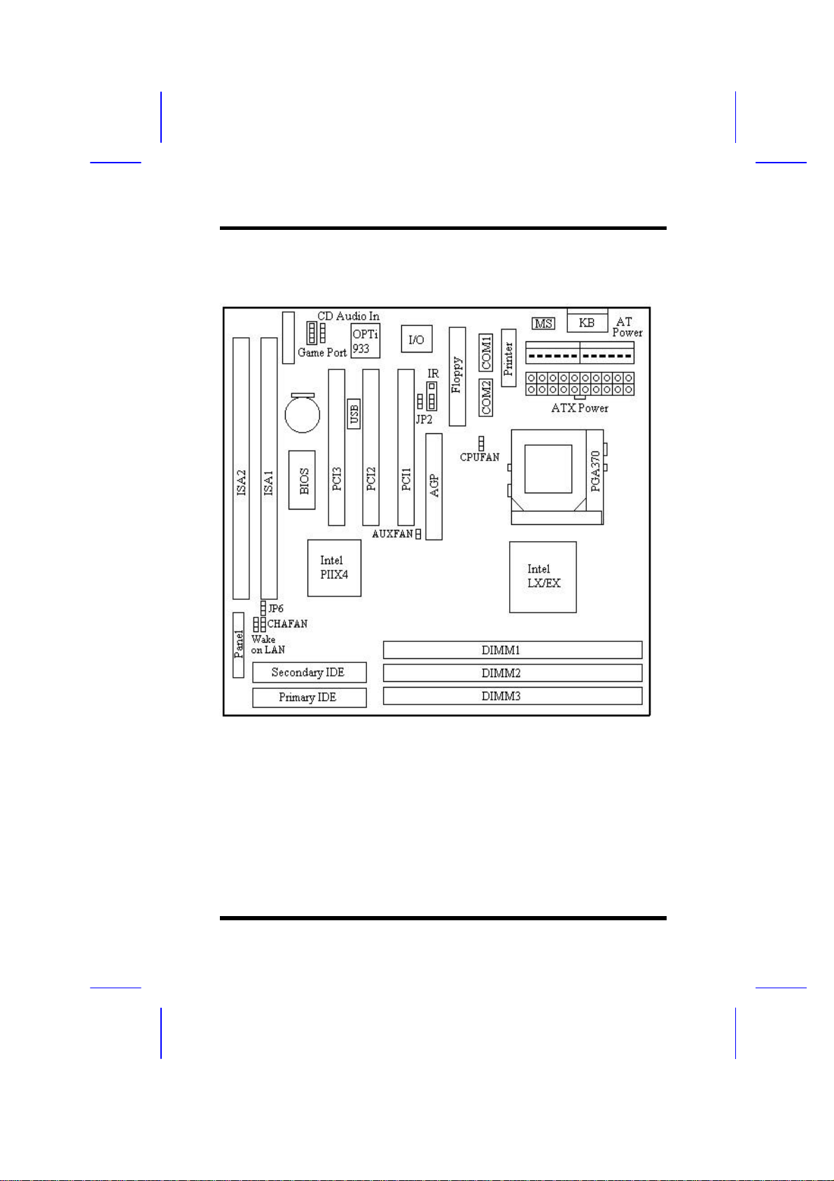
I. PRODUCT INFORMATION
1-4 Mainboard Layout
1-6 ILA USER’S MANUAL
Page 13

Jumpers
I. PRODUCT INFORMATION
1. JP2
4. JP6
Expansion Sockets
1. DIMM 1
2. DIMM 2
3. DIMM 3
Expansion Slots
1. CPU Socket-370
2. ISA Slot 1 & Slot 2
3. PCI Slot 1 to Slot 3
Connectors
1. KB
2. PS/2 Mouse
3. USB
4. COM1/COM2
5. PRINTER
6. ATX POWER
7. AT POWER
8. CPUFAN
9. CHAFAN
10. Floppy
11. Primary IDE
12. Secondary IDE
13. IR
14. Wake on LAN
Keyboard/PS/2 Mouse Power On
(For ATX Power Supply Only)
Clear CMOS (Real Time Clock)
Support 168-pin DIMM Memory
Support 168-pin DIMM Memory
Support 168-pin DIMM Memory
CPU Socket PGA370 for supporting Celeron CPU
16-bit ISA Bus Expansion Slot
32-bit PCI Bus Expansion Slot
AT Keyboard Connector (6-pin female)
PS/2 Mouse Connector (6-pin female)
Universal Serial Bus Port 1 and Port 2
(two 4-pin female)
Serial Port 1 / Serial Port 2 (two 9-pin female)
Printer (Parallel) Port Connector (25-pin female)
ATX Mainboard Power Connector (20-pin block)
Baby AT Mainboard Power Connector
Socket-370 CPU Fan Connector (3 pins)
Chassis Fan Connector (3 pins)
Floppy Drive Connector (34 pins)
Primary IDE Connector (40 pins)
Secondary IDE Connector (40 pins)
Infrared Port Connector (5 pins)
LAN wake up connector
ILA USER’S MANUAL 17
Page 14

I. PRODUCT INFORMATION
15. CD Audio In
16. Panel:
- PWR LED
- KBLCK
- SLP
- SPEAKER
- GRN LED
- HDD LED
- RESET
- PWR ON
CD Audio In Connector
Power LED Connector (3 pins)
Keyboard Lock Switch Connector (2 pins)
Suspend Switch Connector (2 pins)
Chassis Speaker Connector (4 pins)
Green Status LED Connector (3 pins)
HDD LED Connector (4 pins)
Reset Switch Connector (2 pins)
ATX Power Switch Connector (2 pins)
1-8 ILA USER’S MANUAL
Page 15
SECTION 2.
HARDWARE INSTALLATION
This section gives you a step-by-step procedure on how to install your
system. Follow each section accordingly.
2-1 Jumper Settings
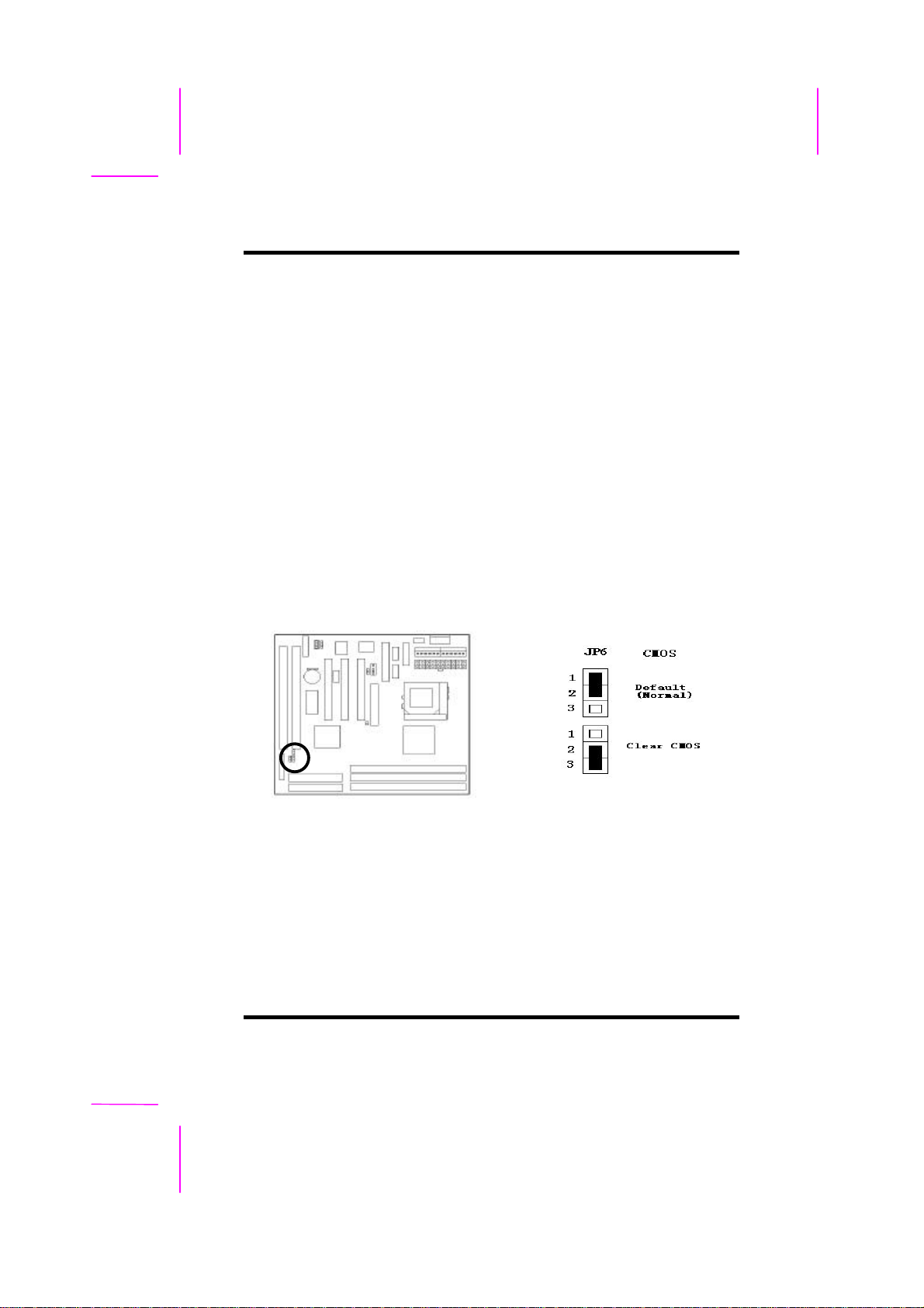
Please refer the following figures for the locations of the jumpers on the
mainboard.
2-1.1 CMOS Clear Setting
To clear CMOS, please follow the steps below:
1. Power off the system and unplug the chassis AC power cord.
2. Short JP6 at pin 2-3 for few seconds.
3. Set JP6 back to its Normal position at pin 1-2.
4. Plug the AC power cord to the chassis.
5. Power on the system and load the BIOS setup default.
ILA USER'S MANUAL 2-1
Page 16
II.HARDWARE INSTALLATION
2-1.2 CPU Type Setting
Auto CPU Type Setting:
This mainboard supports jumperless CPU type setting, no jumper or switch is
needed. The CPU Clock Radio of socket PGA370 Celeron CPU is fix (locked),
all you need to do for CPU Type setting is load “BIOS Setup Defaults” values
to set CPU Clock Frequency at default 66MHz. Then the CPU Type will be
automatically detected by BIOS.
Manual CPU Type Setting:
This mainboard also supports CPU over-clocking by adjusting the CPU Clock
Frequency under “CHIPSET FEATURES SETUP” IN bios Setup.
System Frequency = CPU Clock Radio x CPU Clock Frequency
The available CPU Clock Frequency setting are: 66/68.5/75.0/83.3MHz
Warning: Normally, Intel 440EX/LX Chipset supports 66MHz CPU Clock
Frequency, the other CPU Clock Frequency 75.0/83.3MHz are available only
for internal test or end-user over-clocking testing, which may cause your
system unstable or serious damage.
2-1.3 Power Supply Type
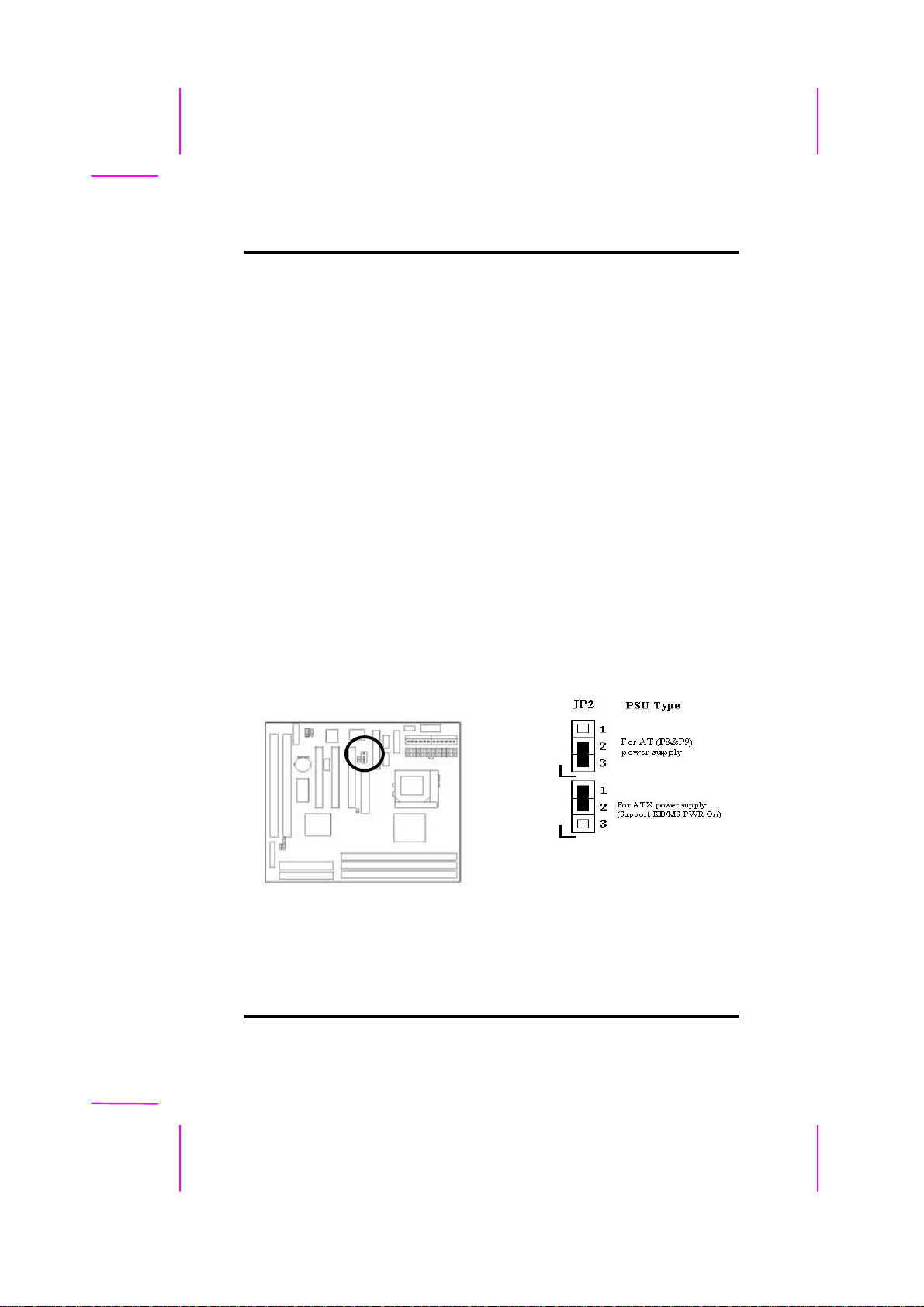
The mainboard supports two kinds of system power supply, AT (P8&P9) and
ATX. For AT power supply, set JP2 at pin 2-3 to use power switch/button to
power on your system. For power supply, set JP2 at pin1-2 and you can
enable or disable KB/PS/2 mouse power on under BIOS Setup/Integrated
2-2 ILA USER’S MANUAL
Page 17
II.HARDWARE INSTALLATION
Peripherals. If you want to use the “Keyboard Power On” function, make sure
you have a 300mA/+5vSB or above ATX power supply and the supporting
mainboard BIOS.
2-2 Connectors
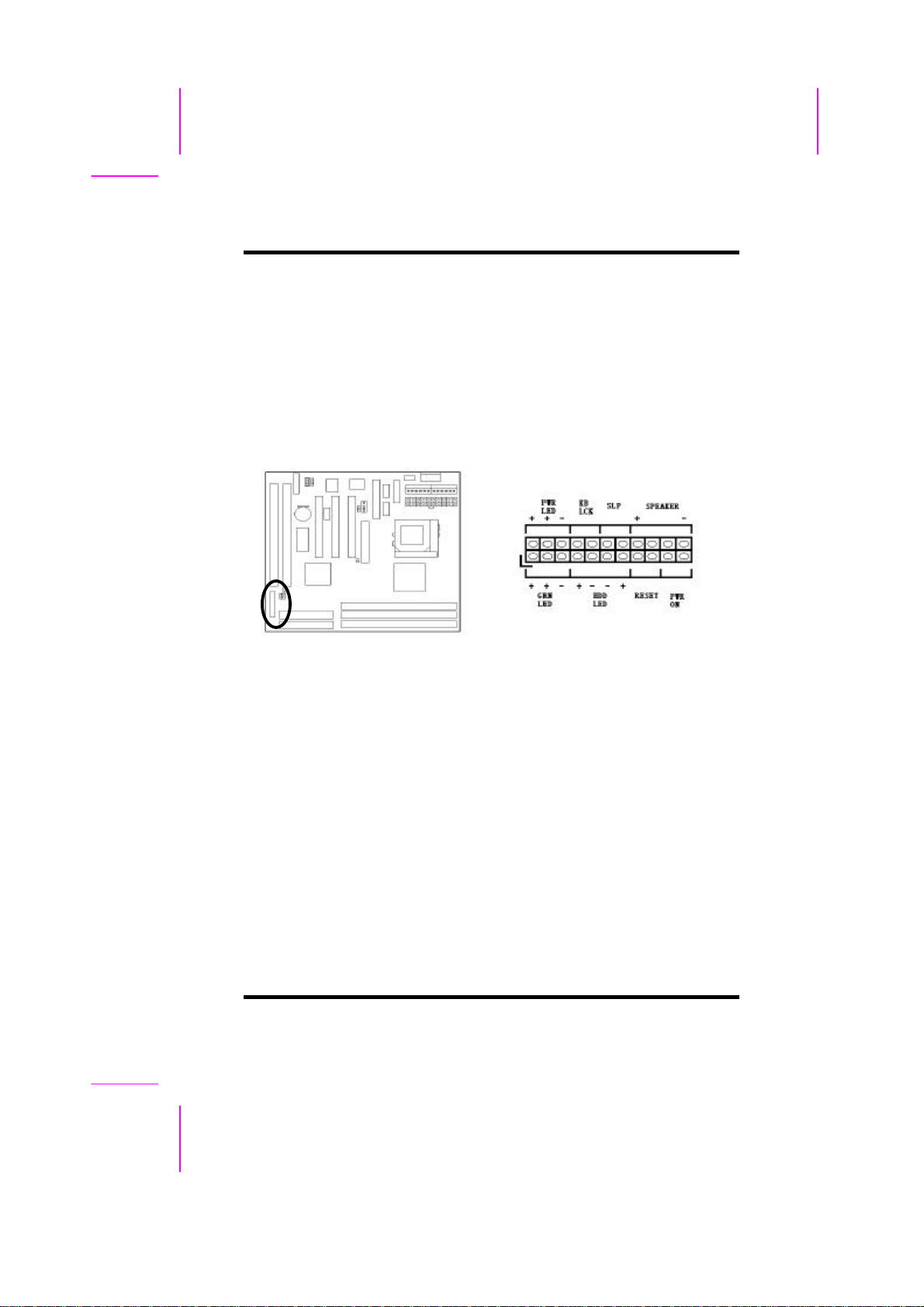
2-2.1 Panel Connector
- PWR LED
- KBLCK
- SLP
- SPEAKER
- GRN LED
- HDD LED
- RESET
ATX Power LED Connector (3 pins)
Keyboard Lock Switch Connector (2 pins)
Suspend Switch Connector (2 pins)
Chassis Speaker Connector (4 pins)
Green Status LED Connector (3 pins)
HDD LED Connector (4 pins)
Reset Switch Connector (2 pins)
ILA USER'S MANUAL 2-3
Page 18
II.HARDWARE INSTALLATION
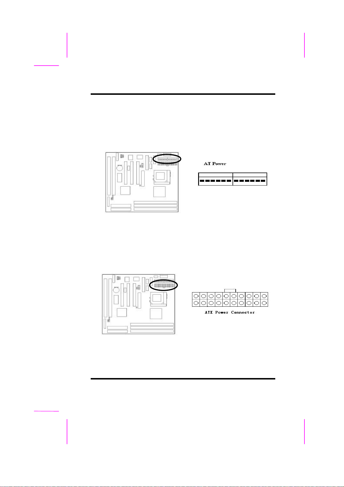
2-2.2 AT Power Connector
Connect the 12-pin AT power supply cable to this power connector. Make sure
the right plug-in direction and the power supply is off before connecting or
disconnecting the power cable.
2-2.3 ATX Power Connector
Connect the 20-pin ATX power supply cable to this power connector. Make
sure the right plug-in direction and the power supply is off before connecting
or disconnecting the power cable.
2-4 ILA USER’S MANUAL
Page 19
II.HARDWARE INSTALLATION
2-2.4 Fan Connectors
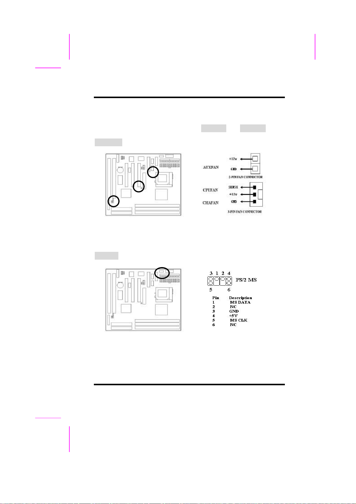
Connect the CPU and Chassis Fan cables to the 3-pin fan connectors shown
below. The fan connectors are marked as CPUFAN and CHAFAN on the
mainboard. Connect Auxiliary Fan cable to the 2-pin fan connector marked as
AUXFAN.
2-2.5 PS/2 Mouse Connector
Connect the PS/2 mouse to the onboard 6-pin Mini-Din connector marked as
PS/2 MS.
ILA USER'S MANUAL 2-5
Page 20
II.HARDWARE INSTALLATION
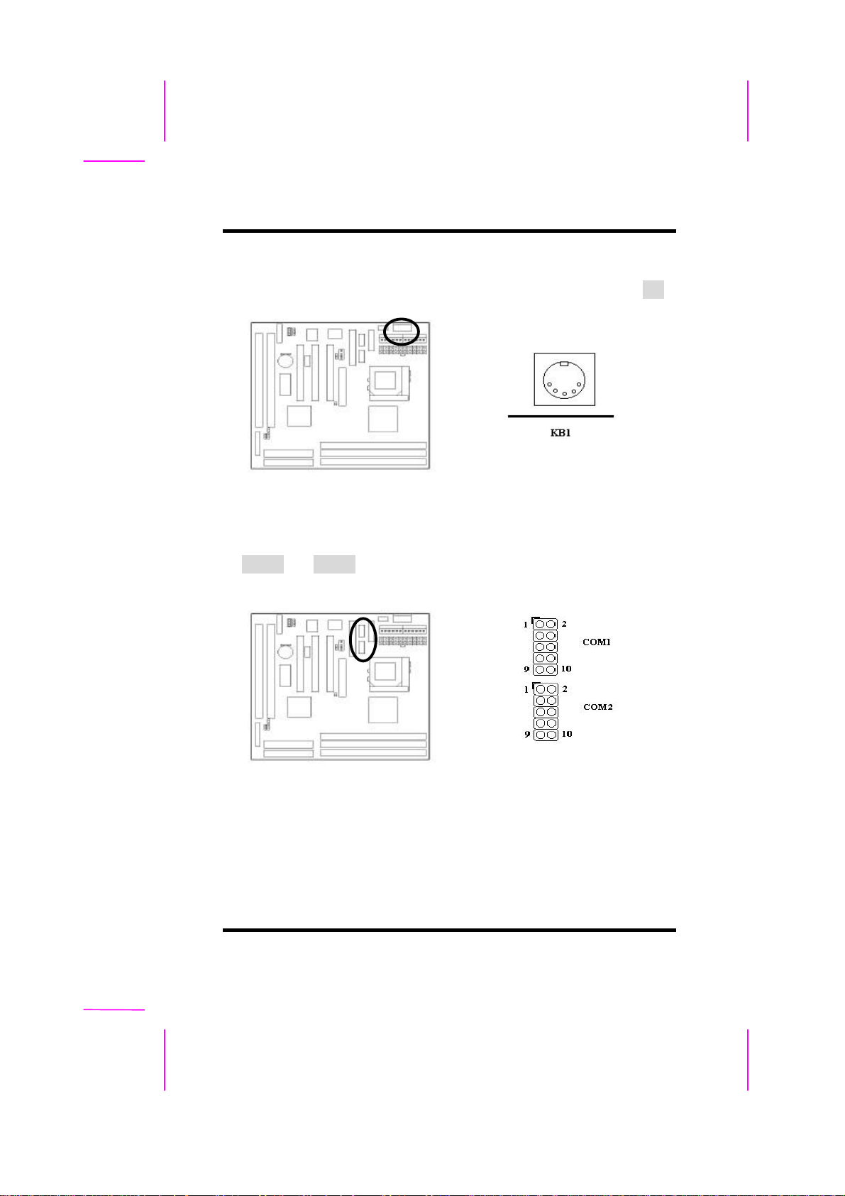
2-2.6 Keyboard Connector
Connect the AT keyboard to the onboard keyboard connector marked as KB.
2-2.7 Serial Device(COM1/COM2) Connectors
Connect your serial device(s) to the onboard 9-pin serial connectors marked
as COM1 and COM2.
2-6 ILA USER’S MANUAL
Page 21
II.HARDWARE INSTALLATION
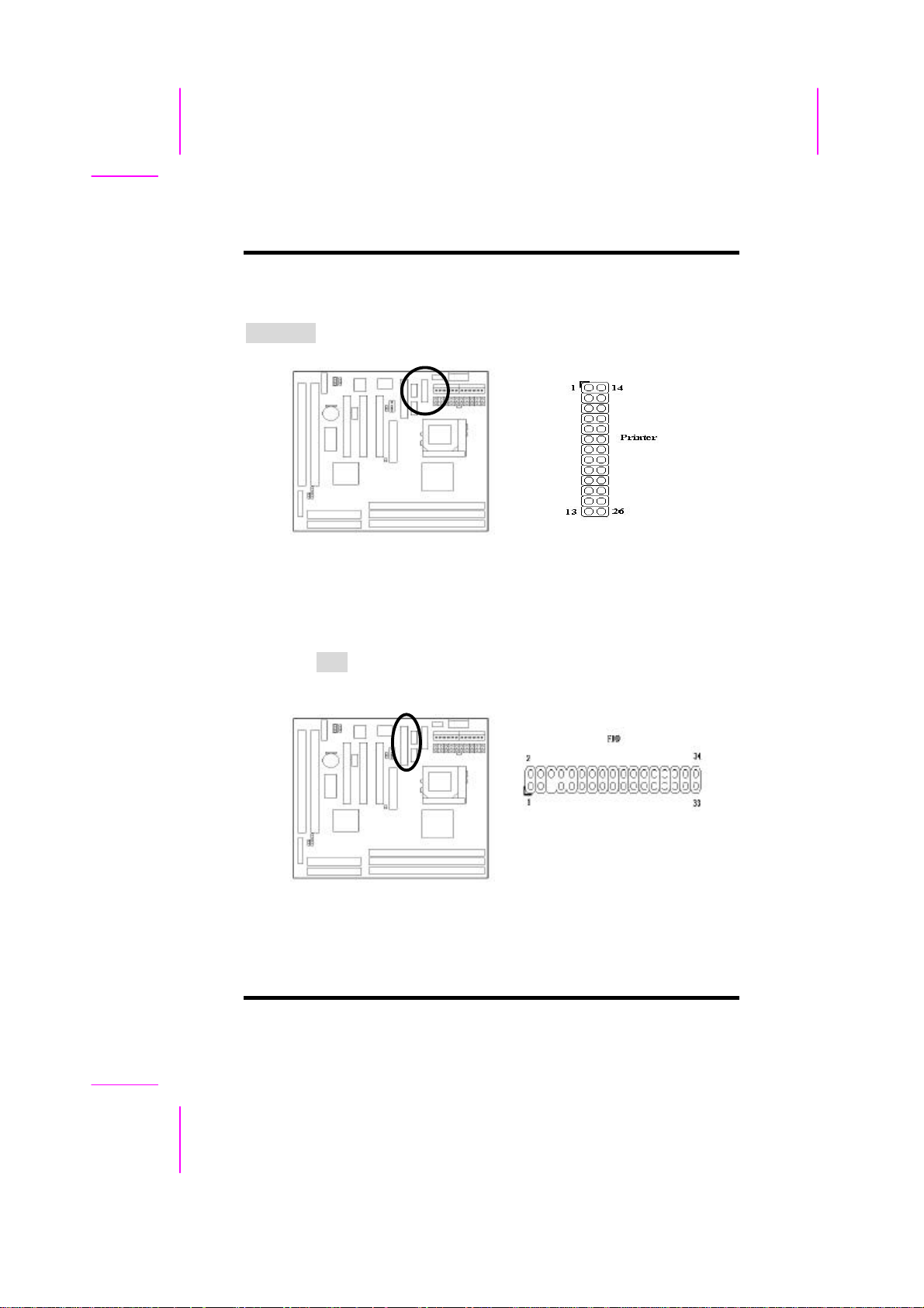
2-2.8 Printer Connctor
Connect your local printer to the onboard 25-pin printer connector marked as
PRINTER.
2-2.9 Floppy Drive Connector
Connect the floppy drive cable to the onboard 34-pin floppy drive connector
marked as FDD.
ILA USER'S MANUAL 2-7
Page 22
II.HARDWARE INSTALLATION
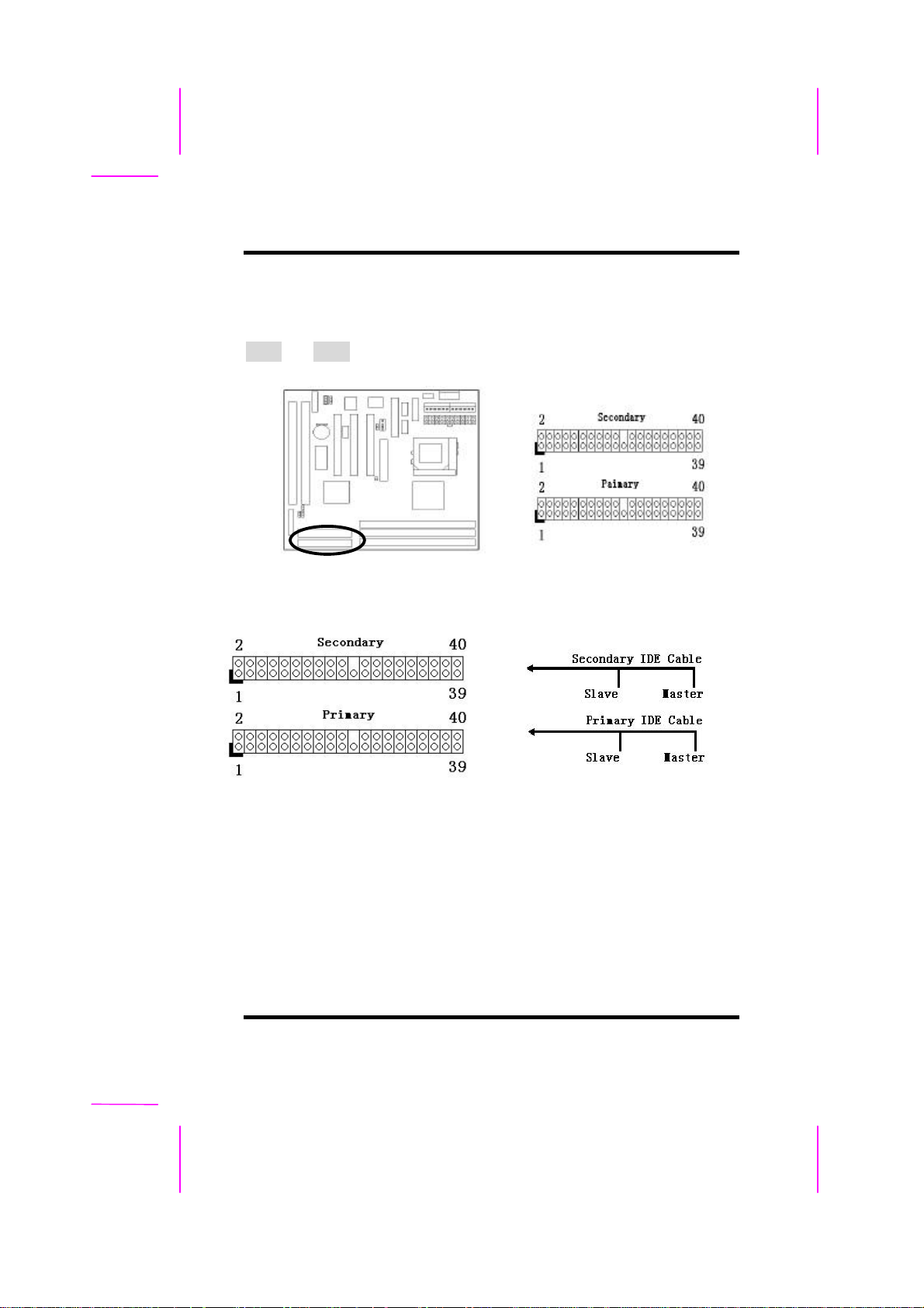
2-2.10 IDE Hard Disk and CD-ROM Connector
Connect your IDE devices to the onboard 40-pin IDE connectors marked as
IDE1 and IDE2.
It is suggested that you connect the IDE devices to your IDE cables as the
figure shown above. Each IDE channel, either Primary or Secondary, supports
two IDE devices which must be set differently to master mode and slave
mode.
(Refer to your hard disk and CD-ROM user’s manual for detailed settings of
IDE master and slave mode.)
2-8 ILA USER’S MANUAL
Page 23
II.HARDWARE INSTALLATION
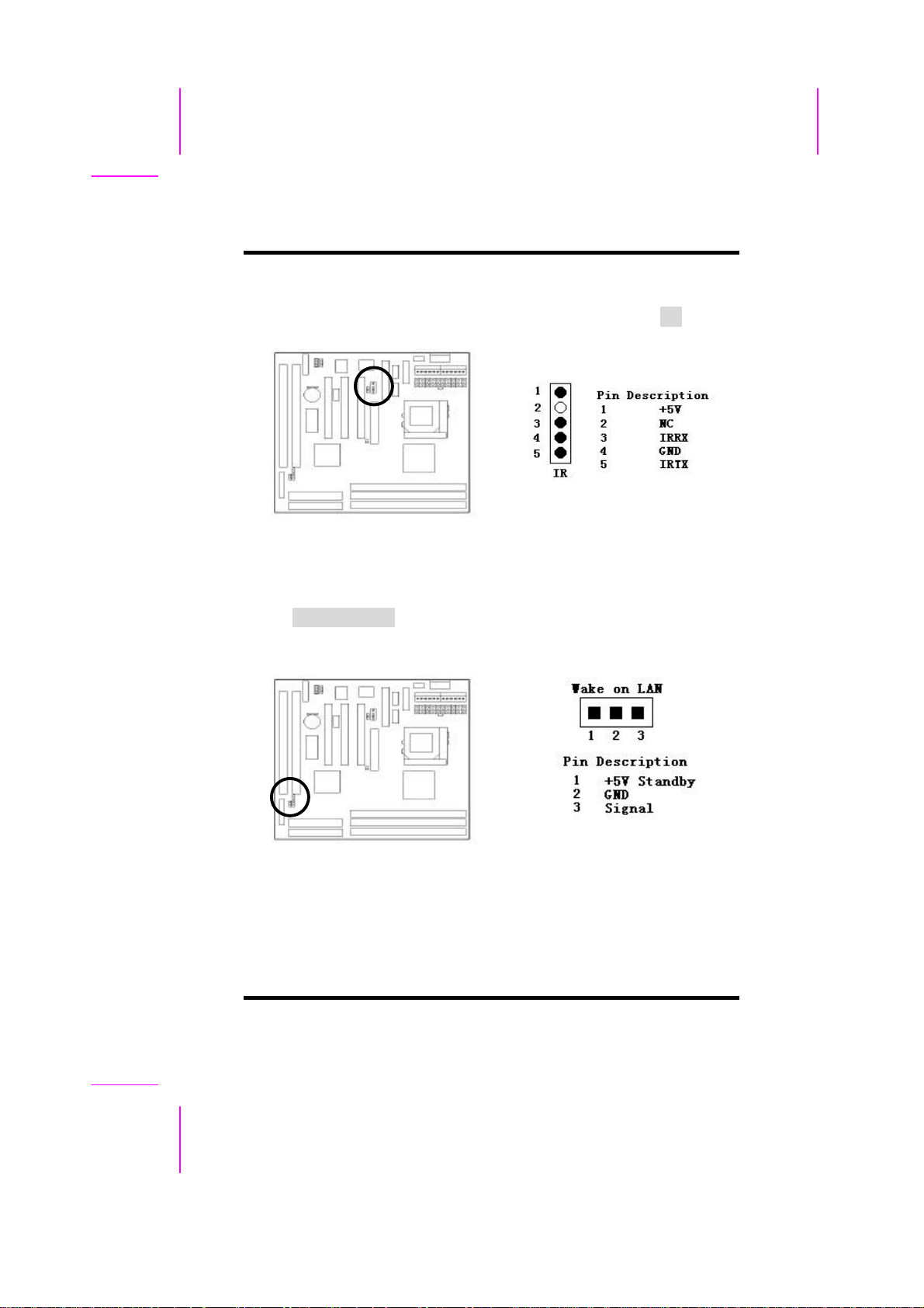
2-2.11 IrDA Connector
Connect your IR device to the onboard IrDA connector marked as IR.
2-2.12 Wake on LAN Connector
This mainboard supports wake up on LAN function. To use this function, you
need a Wake on LAN supported network card and software.
ILA USER'S MANUAL 2-9
Page 24
II.HARDWARE INSTALLATION
2-3 System Memory Installation
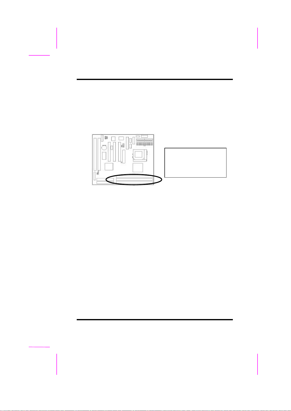
There are 3 pcs 168-pin DIMM (Dual Inline Memory Module) sockets on the
mainboard which support Synchronous DRAM and Registered SDRAM, and
allow you install system memory maximum up to 768MB.
There are 3 168-pin DIMM
sockets that allow you to
install system memory
maximum up to 384MB
2-3.1 Type
This mainboard supports Synchronous DRAM and Registered SDRAM.
However, mixing SDRAM and Registered SDRAM is not allowed. Install one
type only in your system for better compatibility.
2-3.2 Speed
The memory speed normally marked as: -15, -12, -10, -7, -8, PC-100.
The meaning is,
-15 = 15ns, and the maximum clock is 66MHz
-12 = 12ns, and the maximum clock is 83MHz
-10 = 10ns, and the maximum clock is 100MHz
-8 = 8ns, and the maximum clock is 125MHz
-7 = 7ns, and the maximum clock is 142MHz
PC-100 = New Intel specification for high memory speed
With 100MHz or above CPU Bus Clock.
2-10 ILA USER’S MANUAL
Page 25
II.HARDWARE INSTALLATION
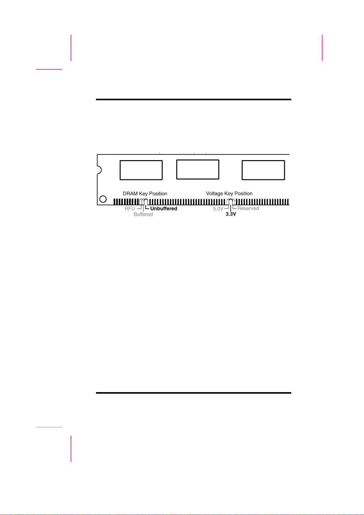
2-3.3 Buffered and Non-buffered
Only the non-buffered DIMM can be used in this mainboard.
The difference between buffered and non-buffered DIMM can be identified by
the notch position shown above.
2-3.4 2-clock and 4-clock signal
Both 2-clock and 4-clock SDRAM DIMM supported by this mainboard.
2-3.5 Parity and Non-parity
This mainboard supports standard 64 bit Non-parity and 72 bit Parity DIMM
modules.
2-3.6 Memory Auto detection by BIOS
This mainboard BIOS can automatically detect the DIMM memory size and
type, so you do not need to adjust any hardware or software settings.
2-3.7 Suggested SDRAM combination
ILA USER'S MANUAL 2-11
Page 26
II.HARDWARE INSTALLATION
This mainboard supports the following SDRAM combination.
DIMM Location
DIMM 1 SDRAM 8, 16, 32, 64 128,MB
DIMM 2 SDRAM 8, 16, 32, 64 128 MB
DIMM 3 SDRAM 8, 16, 32, 64 128 MB
For LX mainboard, Total Memory Size = DIMM1 + DIMM2 + DIMM3
For EX mainboard, Total Memory Size = DIMM1 + DIMM2
DIMM Size
Total System Memory
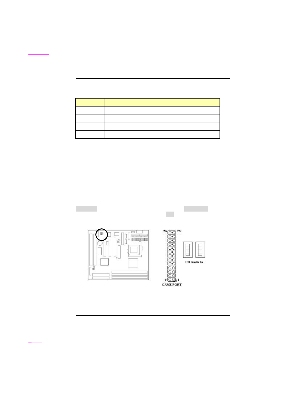
2-4 Game/Audio Connector
Connector the audio cable to the onboard Game/Audio connector marked as
Game port The onboard CD-IN connector marked as CD Audio In is for CDROM audio and MIC-IN connector marked as MIC is for Microphone In.
2-12 ILA USER’S MANUAL
Page 27
SECTION 3.
CMOS SETUP UTILITY
3-1 BIOS Setup Main Menu
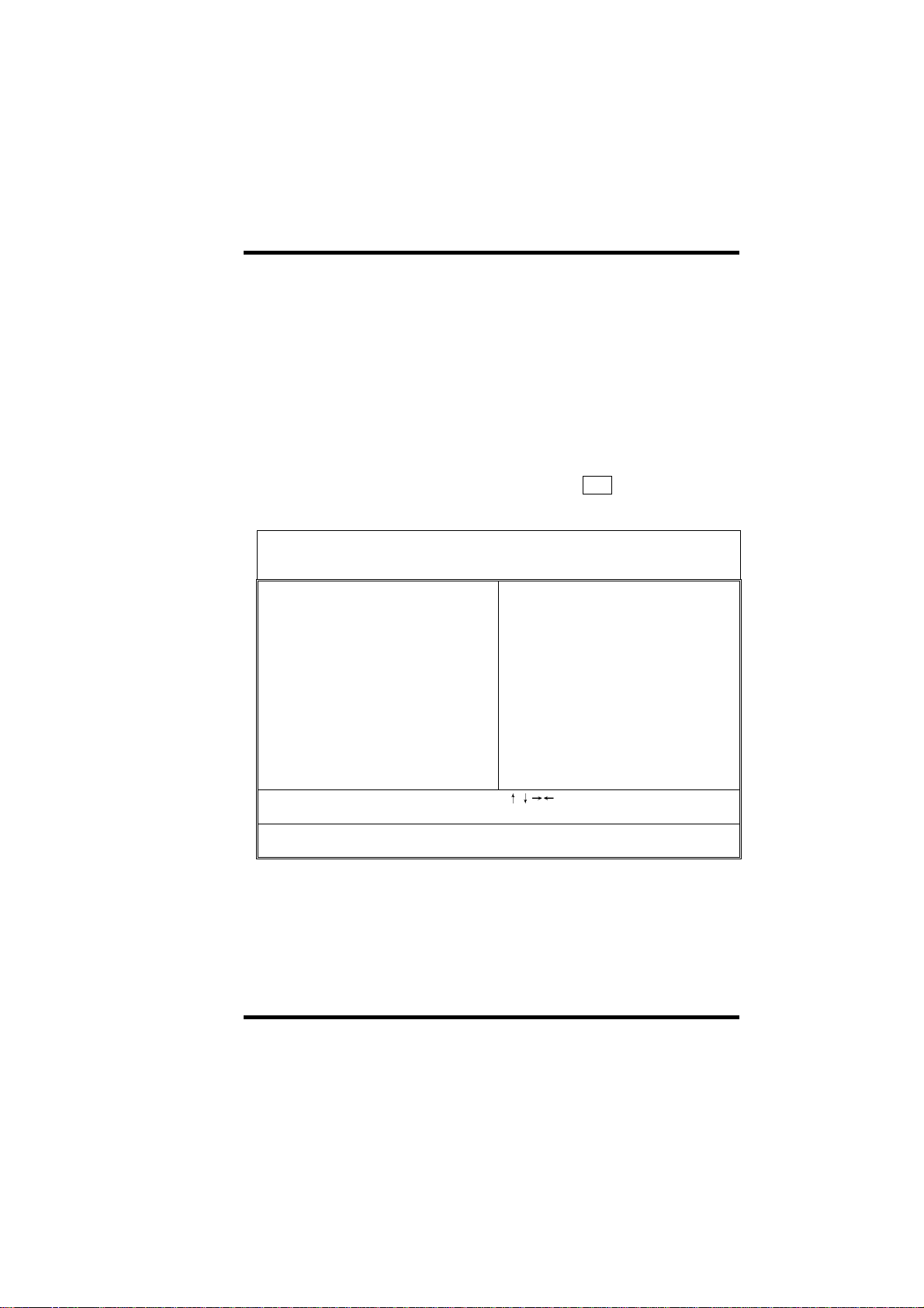
This section tells you how to configure the system by changing BIOS setup
options. To enter the BIOS Setup Utility, press DEL key during POST
(Power-On Self Test). The BIOS Setup Main Menu will appear as shown
below.
ROM PCI/ISA BIOS(00000006)
CMOS SETUP UTILITY
AWARD SOFTWARE, INC.
STANDARD CMOS SETUP INTEGRATED PERIPHERALS
BIOS FEATURES SETUP PASSWORD SETTING
CHIPSET FEATURES SETUP IDE HDD AUTO DETECTION
POWER MANAGEMENT SETUP SAVE & EXIT SETUP
PNP/PCI CONFIGURATION EXIT WITHOUT SAVING
LOAD SETUP DEFAULTS
LOAD TURBO DEFAULTS
Esc: Quit
F10:Save & Exit Setup (Shift)F2:Change Color
The main menu displays a table of items, which defines basic information
about your system. Below are the keyboard function keys you can use under
the menu.
:Select Item
ILA USER’S MANUAL 3-1
Page 28
III. CMOS SETUP UTILITY
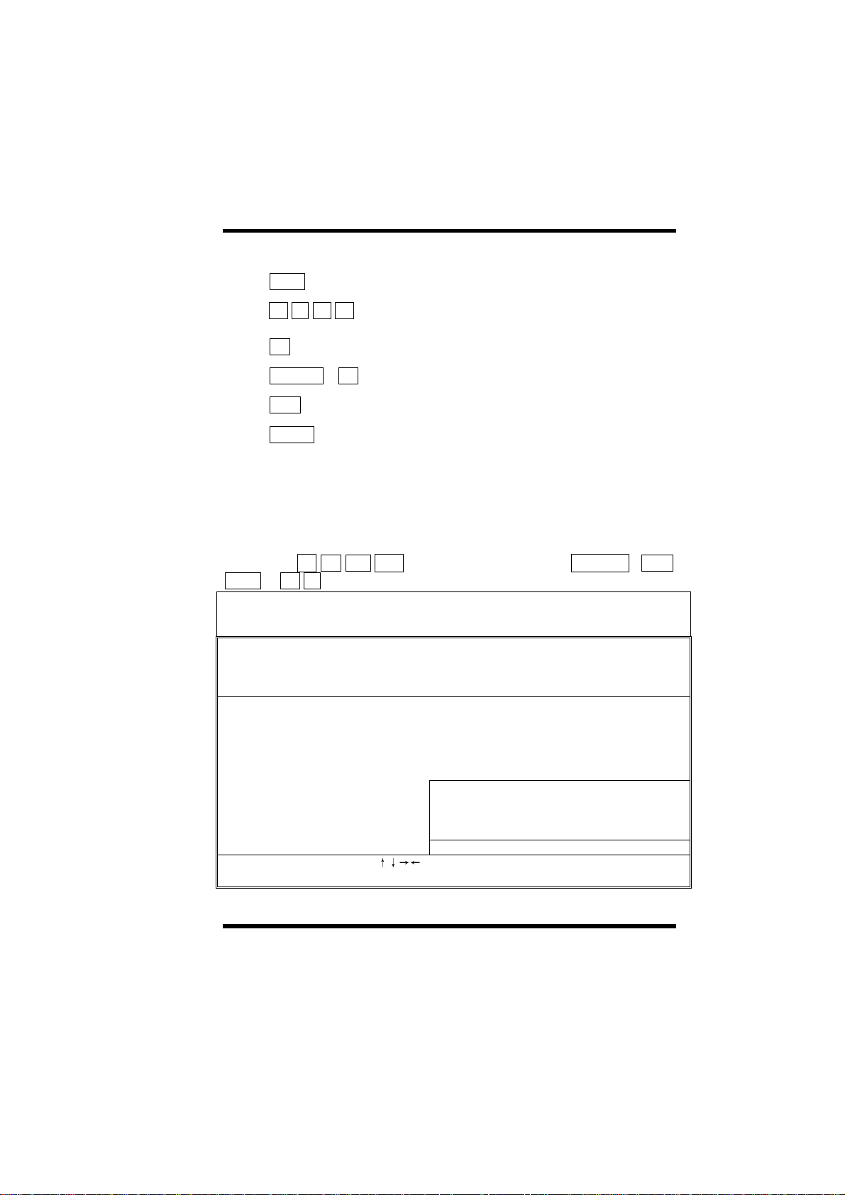
Menu function keys:
E S C
↑ ↓ ←
F 1
S H I F T + F 2
F 1 0
ENTER
3-2 Standard CMOS Setup
This "Standard CMOS Setup" sets the basic system settings such as the date,
time, and the hard disk type, Video display type and error handling. Use the
arrows keys ↑
Down or + - to set the value for each item.
Date (mm:dd:yy): Thu, Apr 30 1998
Time (hh:mm:ss): 14: 8: 0
↓ ← →
To close the BIOS Setup Utility.
To move around the screen. An item is highlighted
→
if it is selected.
To displays information about the highlighted item
you selected.
To Change the color scheme.
To save the changes before exit the BIOS Setup
Utility.
To select or enter a submenu.
to highlight an item and use Page Up / Page
ROM PCI/ISA BIOS(00000006)
STARDARD CMOS SETUP
AWARD SOFTWARE, INC.
HARD DISKS
Primary Master
Primary Slave
Secondary Master
Secondary Slave
Drive A : 1.44M, 3.5in Base Memory: 0K
Drive B : None Extended Memory: 0K
Video : EGA/VGA
Halt On : All Errors Total Memory: 512K
ESC: Quit
F1: Help (Shift)F2:Change Color
TYPE SIZE CYLS HEAD PRECOMP LANDZ SECTOR MODE
: Auto 0 0 0 0 0 0 AUTO
: Auto 0 0 0 0 0 0 AUTO
: Auto 0 0 0 0 0 0 AUTO
: Auto 0 0 0 0 0 0 AUTO
Other Memory: 512K
:Select Item
PU/PD/+/-: Modify
3-2 ILA USER’S MANUAL
Page 29

III. CMOS SETUP UTILITY
Ø Date
To set the date, highlight the date area. Press + / - or Page Up / Page
Down to set the current date. The date format is month: Jan. ~ Dec., date:
1 ~ 31, and year: 1994 ~ 2079.
Ø Time
To set the time, highlight the time area. Press + / - or Page Up / Page
Down to set the current time. The time format is hour: 00 ~ 23, minute: 00 ~
59, and second: 00 ~ 59.
Ø Hard Disks à Primary Master
Ø Hard Disks à Primary Slave
Ø Hard Disks à Secondary Master
Ø Hard Disks à Secondary Slave
TYPE:
- Auto
- User
- None
MODE:
- AUTO
- NORMAL
- LBA
- LARGE
This item lets you set your system IDE hard disk type.
Select Auto to let BIOS automatically detect the installed
hard disk when system boot up. Select User if you prefer
manually enter the hard disk type. The available
parameters are SIZE(HDD Size), CYLS(No. of Cylinder),
HEAD(No. of Head), PRECOMP(Pre-compensation),
LANDZ(Landing Zone), SECTOR(No. of Sector) and
MODE(HDD Mode). Select None if there is no hard disk
connected to the system.
Default: Auto
Select NORMAL for IDE HDD smaller than 528MB.
Select LBA for IDE HDD over than 528MB and support
LBA(Logical Block Addressing) mode. Select LARGE
for IDE HDD over than 528MB and do not support LBA
mode.
Note: We recommend that you set both IDE HDD
TYPE and MODE to AUTO to let BIOS automatically
detect the hard disk drives for you.
Default: Auto
ILA USER’S MANUAL 3-3
Page 30

III. CMOS SETUP UTILITY
Ø Floppy à Drive A
Ø Floppy à Drive B
Drive A / B:
- None
- 360KB 5.25"
- 1.2MB 5.25"
- 720KB 3.5"
- 1.44MB 3.5"
- 2.88MB 3.5"
Ø Video
Video:
- EGA/VGA
- CGA40
- CGA80
- Mono
Ø Halt On
Halt On:
- All Errors
- No Errors
- All, But Keyboard
- All, But Diskette
- All, But Disk/Key
Select the floppy drive type installed in your system.
The available options for Drive A and Drive B are:
360KB 5.25”, 1.2MB 5.25”, 720KB 3.5”, 1.44MB 3.5”,
2.88MB 3.5” and None.
Default: Drive A => 1.44MB 3.5”
Drive B => None
Select the video display card type installed in your
system. The available types are: EGA/VGA, CGA 40,
CGA 80 and Mono.
Default: EGA/VGA
This item defines the operation of the system POST
(Power On Self Test). You can use this item to select
which kind of errors will cause the system to halt during
POST.
Default: All Errors
3-4 ILA USER’S MANUAL
Page 31
III. CMOS SETUP UTILITY
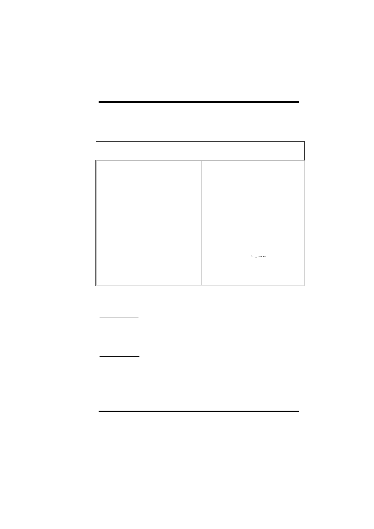
3-3 BIOS Features Setup
This "BIOS Features Setup" option allows you to setup and improve your
system features and performance.
ROM PCI/ISA BIOS(00000008)
BIOS FEATURES SETUP
AWARD SOFTWARE, INC.
Virus Warning :Disabled Video BIOS Shadow :Enabled
External Cache :Enabled CC000-CFFFF Shadow :Disabled
CPU L2 Cache ECC Checking :Enabled D0000-D3FFF Shadow :Disabled
Quick Power On Self Test :Enabled D4000-D7FFF Shadow :Disabled
Boot Sequence :A,C,SCSI D8000-DBFFF Shadow :Disabled
Swap Floppy Drive :Disabled DC000-DFFFF Shadow :Disabled
Boot Up Floppy Seek :Disabled
Boot Up NumLock Status :On
Boot Up System Speed :High
Typematic Rate Setting :Disabled
Typematic Rate (Chars/Sec) :6
Typematic Delay (Msec) :250
Security Option :Setup
PCI/VGA Palette Snoop :Disabled
OS Select For DRAM > 64MB :Non-OS2 ESC: Quit :Select Item
C8000-CBFFF Shadow :Disabled
F1: Help PU/PD/+/-: Modify
F5: Old Values (Shift) F2:Color
F6: Load Setup Defaults
F7: Load Turbo Defaults
Ø Virus Warning
Virus Warning:
- Enabled
- Disabled
When this item is enabled, BIOS will automatically load AntiVirus program that will prevent your system being infected by
Boot Viruses.
Default: Enabled
Ø External Cache
External Cache:
- Enabled
- Disabled
ILA USER’S MANUAL 3-5
This item controls Enable/Disable the external L2 cache.
Default: Enabled
Page 32

III. CMOS SETUP UTILITY
Ø CPU L2 Cache ECC Checking
CPU L2 Cache ECC
Checking:
- Enable
- Disabled
This item can be used to enable ECC (Error Checking and
Correcting) function of the CPU level-2 cache memory.
When the item is enabled, BIOS will automatically check if
CPU support L2 ECC function. This item will not be
displayed if CPU does not support L2 ECC.
Ø Quick Power On Self Test
Quick Power on
Self test:
- Enable
- Disabled
This item can be used to start operating system quickly by
skip some normal POST checking items.
Ø Boot Sequence
Boot Sequence:
- A,C,SCSI
- C,A,SCSI
- C,CDROM,A
- CDROM,C,A
- D,A,SCSI
- E,A,SCSI
- F,A,SCSI
- SCSI,A,C
- SCSI,C,A
- C only
- LS/ZIP,C
This item defines where the system will look for an
operating system, and the order of priority. The boot up
search sequence shown as left.
Default: Enabled
Default: Enabled
Default: A, C, SCSI
Ø Swap Floppy Drive
Swap Floppy Drive:
- Enabled
- Disabled
If you have two floppy drives in your system, This item
allows you to swap around the assigned drive letters so
that drive A becomes drive B, and drive B becomes drive
A. Default:
Disabled
3-6 ILA USER’S MANUAL
Page 33

III. CMOS SETUP UTILITY
ILA USER’S MANUAL 3-7
Page 34

III. CMOS SETUP UTILITY
Ø Boot Up Floppy Seek
Boot Up Floppy
Seek:
- Enabled
- Disabled
This item controls the system to seek floppy drive during
boot up POST.
Ø Boot Up NumLock Status
Boot Up NumLock
Status:
- On
- Off
This item defines if the keyboard NumLock key is active
when your system is started.
Ø Boot Up System Speed
Boot-up System
Speed:
- High
- Low
This item allows the system boot up with High or Low
speed.
Ø Typematic Rate Setting
Typematic Rate
Setting:
- Enabled
- Disabled
To Enable or Disable the speed of keyboard to send
repeat keystrokes.
Default: Disabled
Default: On
Default: High
Default: Disabled
3-8 ILA USER’S MANUAL
Page 35

III. CMOS SETUP UTILITY
Ø Typematic Rate (Chars/Sec)
Typematic Rate:
- 6
- 8
- 10
- 12
- 15
- 20
- 24
- 30
This item provides typematic rate setting, which
allows you to control the repeated keystrokes speed.
Ø Typematic Delay (Msec)
Typematic Delay:
- 250
- 500
- 750
- 1000
This item provides typematic delay setting, which
allows you control the delay time between the first and
the second keystroke.
Ø Security Option
Security Option:
- Setup
- System
The “Setup” option is for password request in entering
BIOS setup.
The “System” option is for password request in
entering setup and system boot up.
Default: 6
Default: 250
Default: Setup
Ø PCI/VGA Palette Snoop
PCI/VGA Palette
Snoop:
- Enabled
- Disabled
ILA USER’S MANUAL 3-9
Set this item to Enabled to reduce display problem
when both PCI VGA and some graphic accelerator
devices such as MPEG/Video capture cards are
installed in your system.
Default: Disabled
Page 36

III. CMOS SETUP UTILITY
Ø OS Select for DRAM > 64MB
OS Select for
DRAM > 64MB:
- OS/2
- Non-OS/2
This item is to patch that OS/2 can not report correct
memory size for more than 64 MB. Set it to OS/2 if you
have an OS/2 installed and have over 64MB system
memory.
Default: Non-OS/2
Ø Video BIOS Shadow
Video BIOS
Shadow:
- Enabled
- Disabled
This item defines if you leave default setting, video
BIOS memory will be copied from ROM into DRAM
area to enhance system performance as DRAM access
time is faster than ROM.
Default: Enabled
Ø C8000-CBFFF Shadow to DC000-DFFFF Shadow
C8000-CBFFF to
DC000-DFFFF
Shadow:
- Enabled
- Disabled
Set Enabled if you know the address that your add on
card ROM used to shadow them. If the item is Enabled,
BIOS will copy the selected area from ROM to RAM to
increase system performance.
Default: Disabled
3-10 ILA USER’S MANUAL
Page 37

III. CMOS SETUP UTILITY
3-4 Chipset Features Setup
This option displays a table of items, which define timing parameters of the
mainboard components including the graphic system, memory, and the
system logic. In general rule, you should leave the items on this page at the
default values unless you are familiar with the technical specifications of your
hardware. If you change the values, you may introduce fatal errors or
recurring instability into your system.
ROM PCI/ISA BIOS(00000008)
CHIPSET FEATURES SETUP
AWARD SOFTWARE, INC.
Auto Configuration :Enabled Pentium II Micro Codes :Enabled
Power Supply Type :ATX
DRAM Speed Selection :60ns
MA Wait State :Slow ********* Jumpless Setup **********
EDO RAS# to CAS# Delay :3 CPU Clock Frequency :66.8MHz
EDO RAS# Precharge Time :4
EDO DRAM Read Burst :x333
EDO DRAM Write Burst :x333
SDRAM(CAS Lat/RAS-to-CAS) :3/3
SDRAM RAS Precharge Time :3 T
DRAM ECC Function :Disabled
CPU-To-PCI IDE Posting :Enabled
Video BIOS Cacheable :Disabled
Video RAM Cacheable :Disabled
8 Bit I/O Recovery Time :4
16 Bit I/O Recovery Time :2 ESC: Quit
Memory Hole At 15M-16M :Disabled F1: Help PU/PD/+/-: Modify
Passive Release :Enabled F5: Old Values (Shift) F2:Color
Delayed Transaction :Enabled F6: Load Setup Defaults
AGP Aperture Size(MB) :64 F7: Load Turbo Defaults
:Select Item
ILA USER’S MANUAL 3-
11
Page 38

III. CMOS SETUP UTILITY
Ø Auto Configuration
Auto Configuration:
- Enabled
- Disabled
Leave this item at the default value Enabled. This will
automatically install the correct values for the system
DRAM timing. Set Disabled if you want to specify
your own DRAM timing.
Ø DRAM Speed Selection
DRAM Speed
Selection:
- 50ns
- 60ns
This item allows you set your DRAM speed, 50ns or
60ns.
Ø MA Wait State
MA Wait State:
- Slow
- Fast
This item defines DRAM MA (Memory Address) wait
state. Set it to Fast when DRAM loading is heavy or
the speed is lower.
Default: Enabled
Default: 60ns
Default: Slow
Ø EDO RAS# To CAS# Delay
EDO RAS# To CAS#
Delay:
- 2
- 3
This item defines the delay state between DRAM Row
Address Strobe (RAS) and Column Address Strobe
(CAS).
Default: 3
3-12 ILA USER’S MANUAL
Page 39

III. CMOS SETUP UTILITY
Ø EDO RAS# Precharge Time
EDO RAS#
Precharge Time:
- 3
- 4
This item defines the waiting time after issuing a
precharge command to EDO.
Ø EDO DRAM Read Burst
EDO DRAM Read
Burst:
- X222
- X333
This item defines the four continuous memory reading
from EDO DRAM within one read burst cycle.
Ø EDO DRAM Write Burst
EDO DRAM Write
Burst:
- X222
- X333
This item defines the four continuous memory writing
to EDO DRAM within one write burst cycle.
Ø SDRAM (CAS Lat/RAS-to-CAS)
SDRAM (CAS
Lat/RAS-to-CAS):
- 2/2
- 3/3
SDRAM CAS Latency defines the latency between
SDRAM read command and the actual data time.
SDRAM RAS-to-CAS Delay defines the latency
between SDRAM active command and the read/write
command.
It is an important SDRAM parameter. If your SDRAM
has unstable problem, try set this item to 3T.
Default: 3
Default: X333
Default: X333
Default: 3/3
ILA USER’S MANUAL 3-
13
Page 40

III. CMOS SETUP UTILITY
Ø SDRAM RAS Precharge Time
SDRAM RAS
Precharge Time:
- 2T
- 3T
This item defines the waiting time after issuing a
SDRAM Precharge command.
Ø DRAM ECC Function
DRAM ECC
Function:
- Enabled
- Disabled
This item enables/disables ECC (Error Checking and
Correction) for the main memory. We recommend
that you leave this item at Disabled if you have not
verified that your memory modules support ECC. To
use this function, you need 72 bits (64+8 bit parity)
DIMM.
Ø CPU-To-PCI IDE Posting
CPU-To-PCI IDE
Posting:
- Enabled
- Disabled
This item defines CPU to IDE posting cycle. Set it to
disabled if you have any IDE compatibility problem.
Default: 3T
Default: Disabled
Default: Enabled
3-14 ILA USER’S MANUAL
Page 41

Ø Video BIOS Cacheable
III. CMOS SETUP UTILITY
Video BIOS
Cacheable:
This item allows the video BIOS to be cached for
faster video performance.
- Enabled
- Disabled
Ø Video RAM Cacheable
Video RAM
Cacheable:
- Enabled
- Disabled
This item allows the Video RAM to be cached for
faster video performance.
Default:
Disabled
Ø 8 Bit I/O Recovery Time
Ø 16 Bit I/O Recovery Time
8 Bit I/O Recovery
Time:
- 1
- 2
- 3
- 4
- 5
- 6
- 7
- 8
- NA
16 Bit I/O Recovery Time:
- 1
- 2
- 3
- 4
- NA
This two items set timing parameters for 8-bit and 16bit ISA expansion cards.
Default: Disabled
Default: 8-Bit I/O Recovery Time => 4
16-Bit I/O Recovery Time => 2
Ø Memory Hole At 15M-16M
ILA USER’S MANUAL 3-
15
Page 42

III. CMOS SETUP UTILITY
Memory Hole At
15M-16M:
- Enabled
- Disabled
This item can be used to reserve memory space for
some ISA cards that require it.
Default: Disabled
3-16 ILA USER’S MANUAL
Page 43

Ø Passive Release
Ø Delayed Transaction
III. CMOS SETUP UTILITY
Passive Release,
Delayed Transaction:
- Enabled
- Disabled
These two items make the PCI Bus Compliant with
the PCI Specification ver. 2.1.
Ø AGP Aperture Size (MB)
AGP Aperture Size
(MB):
- 4
- 8
- 16
- 32
- 64
- 128
- 256
This item defines the effective memory size of the
AGP Aperture.
Ø Pentium II Micro Codes
Pentium II Micro
Codes:
- Enabled
- Disabled
This item defines the Pentium II Micro Codes which
are used to resolve Pentium II CPU bugs. We
recommend that you leave this item at the default
value for better reliability.
Default: Enabled
Default: 64
Default: Enabled
ILA USER’S MANUAL 3-
17
Page 44

III. CMOS SETUP UTILITY
Ø Power Supply Type
Power Supply Type:
- ATX
- P8&P9
-Auto
This item allows you set your system power supply
type. Select ATX for ATX power supply and P8&P9
for At power supply. Default:
Auto
Note: The following BIOS items can be functioning
only when the system using ATX power supply and
ATX power supply type is selected in this item.
\ CMOS Setup \ Power Management \
-Modem Wake Up
-LAN Wake Up
-RTC Wake Up Timer
-Power Button Override
\ CMOS Setup \ Integrated Peripherals \
-KB Power ON (Ctrl-F1)
-PS2 Mouse Power ON
Ø CPU Clock Frequency
CPU Clock
Frequency:
-66.8MHz
-68.5MHz
-75.0MHz
-83.3MHz
This item allows you set CPU Clock Frequency.
CPU Type CPU Clock Ratio CPU Clock Freq
PGA370-300 4.5X 66.8MHz
PGA370-333 5.0X 66.8MHz
PGA370-366 5.5X 66.8MHz
PGA370-400 6.0X 66.8MHz
PGA370-433 6.5X 66.8MHz
Default: 66.8MHz
Note: CPU supplier Intel has locked The CPU Clock
Ratio of socket PGA370 processor.
Warning: Normally, Intel 440EX/LX Chipset
supports 66MHz CPU Clock Frequency, the other
CPU Clock Frequency 75.0/83.3MHz are available
only for internal test or end-user over-clocking test,
which may cause your system unstable or serious
damage.
3-18 ILA USER’S MANUAL
Page 45
III. CMOS SETUP UTILITY
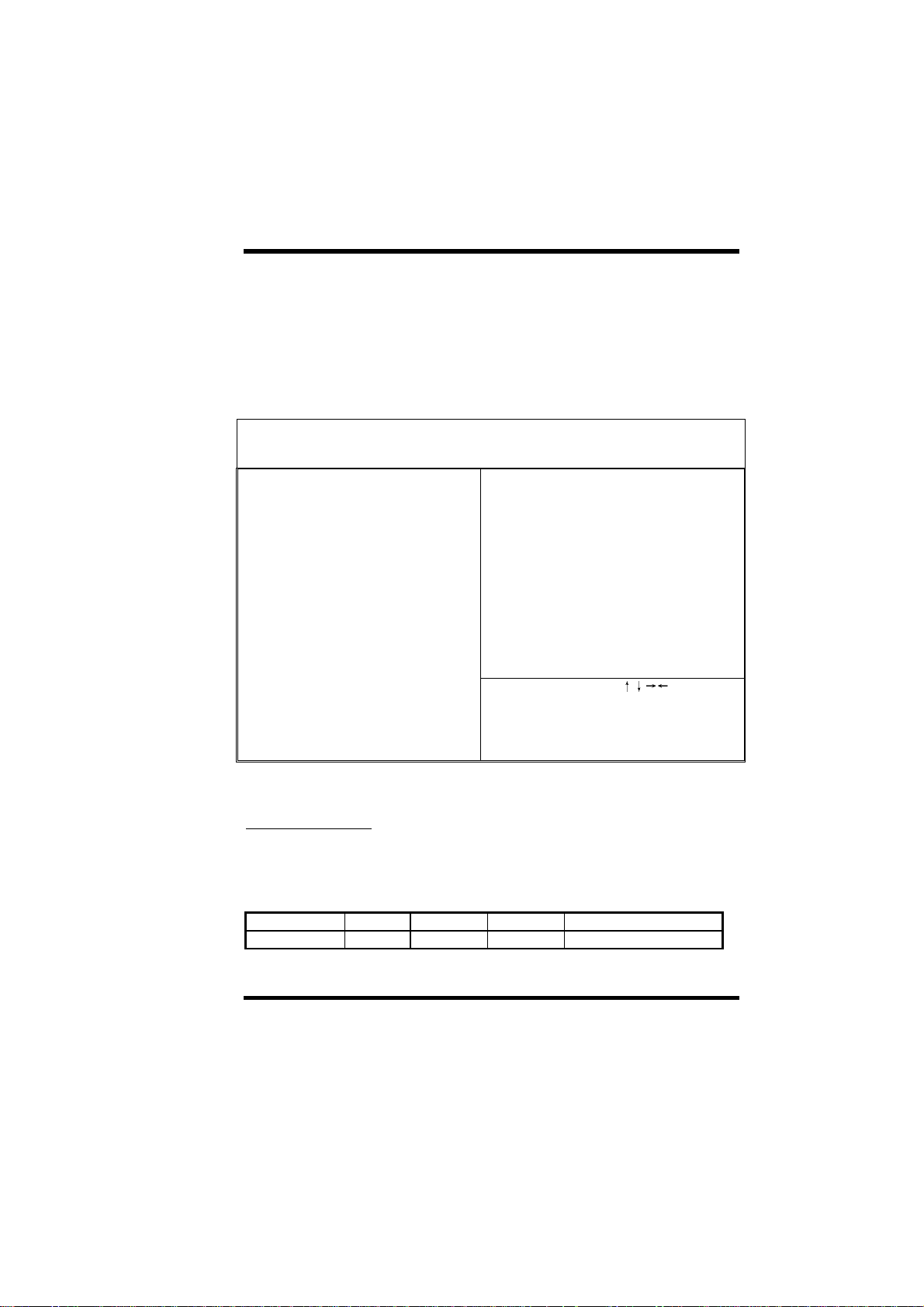
3-5 Power Management Setup
This option displays a table of items, which lets you control the power
management of the system. Modern operating system take care of much of
the routine power management. This mainboard supports ACPI (Advanced
Configuration and Power Interface).
ROM PCI/ISA BIOS(00000008)
POWER MANAGEMENT SETUP
AWARD SOFTWARE, INC.
Power Management : Disabled **Reload Global Timer Events**
PM Control by APM : Yes
Video Off After : Standby IRQ[3-7,9-15],NMI : Enabled
Primary IDE0 : Disabled
Doze Mode : Disabled Primary IDE1 : Disabled
Standby Mode : Disabled Secondary IDE0 : Disabled
Suspend Mode : Disabled Secondary IDE1 : Disabled
HDD Power Down : Disabled Floppy Disk : Disabled
Modem Wake Up : Disabled Serial Port : Enabled
LAN Wake Up : Disabled Parallel Port : Disabled
VGA Active Monitor : Enabled
Power Button Override : Enabled
RTC Wake Up Timer : Disabled
ESC: Quit
**Break Event From Suspend** F1: Help PU/PD/+/-: Modify
F5: Old Values (Shift) F2:Color
IRQ 8 Clock Event : Disabled F6: Load Setup Defaults
F7: Load Turbo Defaults
:Select Item
Ø Power Management
Power Management:
- Max Saving
- Mix Saving
- User Define
- Disabled
Mode Doze Standby Suspend HDD Power Down
Min Saving
ILA USER’S MANUAL 3-
This item allows you to set the default parameters of
power-saving modes. Set to Disable to disable power
management function. Set to User Define to define
your own parameters.
Default: User Define
1 hour 1 hour 1 hour 15 min
19
Page 46

III. CMOS SETUP UTILITY
Max Saving
1 min 1 min 1 min 1 min
Ø PM Controlled by APM
PM Controlled by
APM:
- Yes
- No
Set to Yes to transfer power management control to
APM (Advanced Power Management) and enhance
power saving function.
Ø Video Off After
Video Off After:
- N/A
- Doze
- Standby
- Suspend
To select the power down mode option to turn off
video monitor.
Ø Doze Mode
Doze Mode:
- Disabled
- 1 Min
- 2 Min
- 4 Min
- 8 Min
- 12 Min
- 20 Min
- 30 Min
- 40 Min
- 1 Hour
This item lets you set the timer after which the system
enters into Doze mode from working mode. The
system event is detected by monitoring the IRQ
signals or other I/O events.
Default: Yes
Default: Standby
Default: Disabled
3-20 ILA USER’S MANUAL
Page 47

Ø Standby Mode
III. CMOS SETUP UTILITY
Standby Mode
- Disabled
- 1 Min
- 2 Min
- 4 Min
- 8 Min
- 12 Min
- 20 Min
- 30 Min
- 40 Min
- 1 Hour
Ø Suspend Mode
Suspend Mode:
- Disabled
- 1 Min
- 2 Min
- 4 Min
- 8 Min
- 12 Min
- 20 Min
- 30 Min
- 40 Min
- 1 Hour
This item lets you set the timer after which the system
enters into Standby mode from Doze mode.
In this mode, the monitor power-saving feature
activates. Any activity detected returns the system to
normal full power mode. The system activity is
detected by monitoring the IRQ signals or other I/O
events.
Default: Disabled
This item lets you set the timer after which the system
enters into Suspend mode from Standby mode. The
system activity is detected by monitoring the IRQ
signals or other I/O events.
Default: Disabled
Ø HDD Power Down
ILA USER’S MANUAL 3-
21
Page 48

III. CMOS SETUP UTILITY
HDD Power Down:
- Disabled
- 1 Min
-.....
- 15 Min
This item allows you specify the IDE HDD idle time
before the device enters the power down state. This
item is independent from the power states, Standby
and Suspend Mode.
Ø Modem Wake Up
Modem Wake Up:
- Enabled
- Disabled
To enable or disable Modem Wake Up function.
Ø LAN Wake Up
LAN Wake Up:
- Enabled
- Disabled
To enable or disable LAN Wake Up function.
Ø VGA Active Monitor
VGA Active Monitor:
- Enabled
- Disabled
To enable or disable the detection of VGA activity for
power saving mode.
Default: Disabled
Default: Disabled
Default: Disabled
Default: Enabled
Ø Power Button Override
3-22 ILA USER’S MANUAL
Page 49

III. CMOS SETUP UTILITY
Power Button
Override:
- Enabled
- Disabled
When set to Enabled, the power switch on the front
panel can be used to control power On/Suspend/Off.
Press switch System status
Less than 4 seconds Suspend mode
Longer than 4 seconds Power off
When set to Disabled, the power switch is only used
to control On/Off, no Suspend mode functions.
Default: Enabled
ILA USER’S MANUAL 3-
23
Page 50

III. CMOS SETUP UTILITY
Ø RTC Wake Up Timer
RTC Wake Up
Timer:
- Enabled
- Disabled
To enable or disable the RTC Wake Up function.
Ø WakeUp Date (of Month)
WakeUp Date (of
Month):
- 0
- 1
- .....
- 31
This item displayed only when you enable the RTC
Wake Up Timer item.
You can use this item to specify the date you want to
wake up the system. For Example, if you set to 18,
the system will wake up on the 18th day of every
month. If set to 0, the system will wake up on the
specified time every day.
Ø WakeUp Time (hh:mm:ss)
WakeUp Time
(hh:mm:ss):
- hh:mm:ss
This item is displayed only when you enable the RTC
Wake Up Timer item. You can use this item to specify
the time you want to wake up the system.
Ø IRQ 8 Clock Event
IRQ 8 Clock Event:
- Enabled
- Disabled
OS/2 has periodically IRQ8 RTC(Real Time Clock)
event. When set this item to enabled, OS/2 may has
problem to go into Doze/Standby/Suspend mode.
Default: Disabled
Default: Disabled
Ø IRQ [3-7,9-15],NMI
IRQ [3-7,9-15],NMI:
- Enabled
- Disabled
To enable or disable the detection of IRQ3-7, IRQ915 or NMI interrupts events for power saving mode.
Default: Enabled
3-24 ILA USER’S MANUAL
Page 51

Ø Primary IDE 0
Ø Primary IDE 1
Ø Secondary IDE 0
Ø Secondary IDE 1
Ø Floppy Disk
Ø Serial Port
Ø Parallel Port
III. CMOS SETUP UTILITY
Primary/Secondary
IDE 0/1, Floppy,
Serial & Parallel
Port:
- Enabled
- Disabled
These items enable or disable the detection of IDE,
Floppy, Serial and Parallel port activities for power
saving mode.
Default: Serial Port => Enabled
Others => Disabled
ILA USER’S MANUAL 3-
25
Page 52
III. CMOS SETUP UTILITY
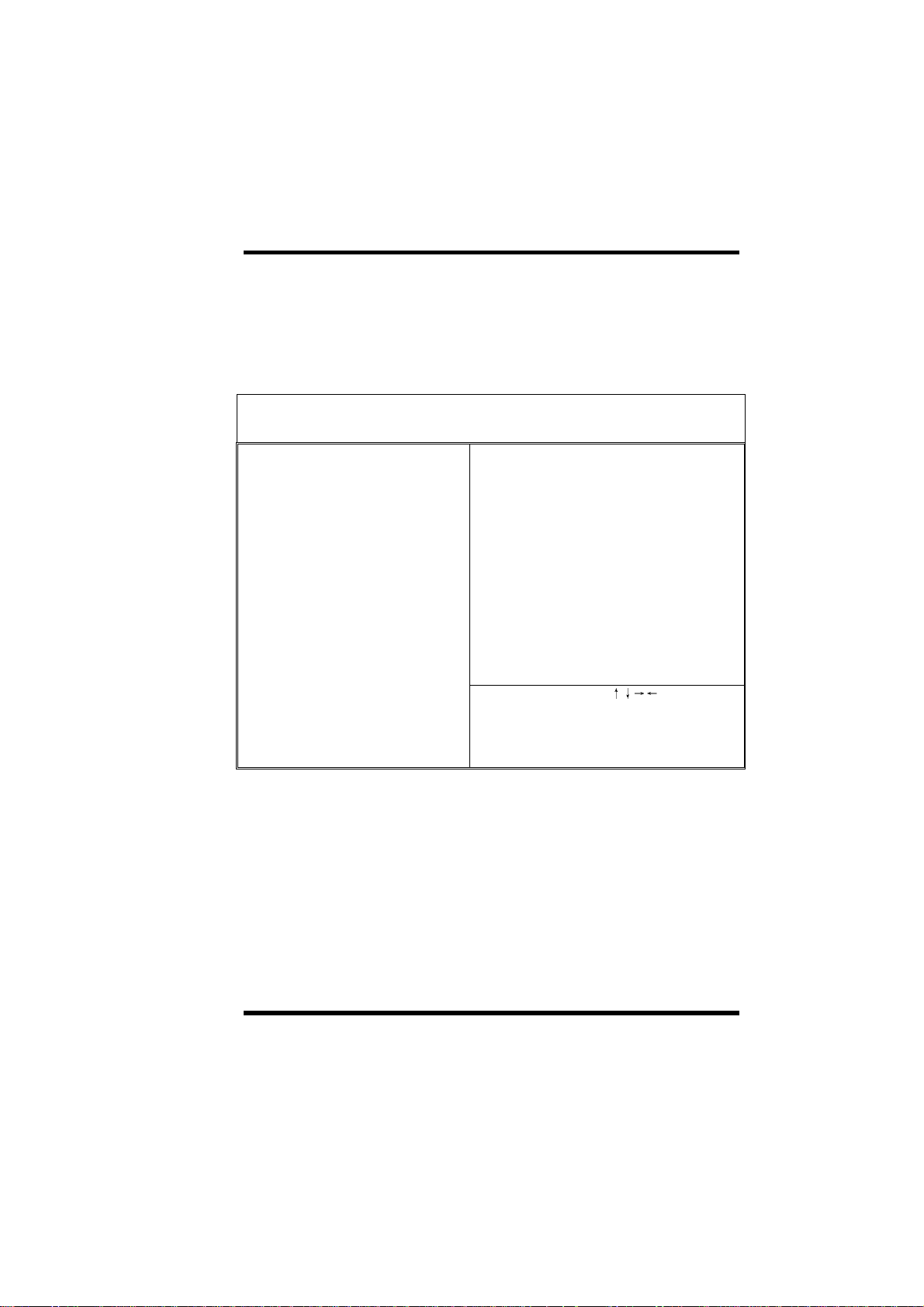
3-6 PNP/PCI Configuration Setup
This option display a table of items that configures how PnP (Plug and Play)
and PCI expansion cards operates in your system.
ROM PCI/ISA BIOS(00000009)
PNP/PCI CONFIGURATION SETUP
AWARD SOFTWARE, INC.
PnP OS Install :No Init VGA First : PCI Slot
Resources Controlled By :Manual PCI IDE IRQ Map To : PCI-AUTO
Reset Configuration Data :Disabled Primary IDE INT# : A
Secondary IDE INT# : B
IRQ-3 assigned to : Legacy ISA
IRQ-4 assigned to : Legacy ISA Used MEM base addr : N/A
IRQ-5 assigned to : PCI/ISA PnP
IRQ-7 assigned to : PCI/ISA PnP PCI Slot1 IRQ(Right) : Auto
IRQ-9 assigned to : PCI/ISA PnP PCI Slot2 IRQ : Auto
IRQ-10 assigned to : PCI/ISA PnP PCI Slot3 IRQ (Left) : Auto
IRQ-11 assigned to : PCI/ISA PnP
IRQ-12 assigned to : PCI/ISA PnP
IRQ-14 assigned to : PCI/ISA PnP
IRQ-15 assigned to : PCI/ISA PnP
DMA-0 assigned to : PCI/ISA PnP
DMA-1 assigned to : PCI/ISA PnP ESC: Quit
DMA-3 assigned to : PCI/ISA PnP F1: Help PU/PD/+/-: Modify
DMA-5 assigned to : PCI/ISA PnP F5: Old Values (Shift) F2:Color
DMA-6 assigned to : PCI/ISA PnP F6: Load Setup Defaults
DMA-7 assigned to : PCI/ISA PnP F7: Load Turbo Defaults
:Select Item
3-26 ILA USER’S MANUAL
Page 53

Ø PnP OS Installed
III. CMOS SETUP UTILITY
PnP OS Installed:
- Yes
- No
Normally, BIOS will allocate the PnP resources during
POST (Power-On Self Test). Set this item to Yes if
you have a PnP operating system such as Windows
95, BIOS will bypass PnP device initial except of boot
device (VGA/IDE or SCSI) and PnP operating system
will do these PnP devices resource allocation. If this
item is set to No, BIOS will handle all PnP devices.
Ø Resources Controlled By
Resources Controlled
by:
- Auto
- Manual
Basically, BIOS will allocate the IRQ/DMA resources
automatically for these PNP/PCI and onboard
devices. The exception might be encountered when
legacy ISA devices are installed, which occupies
resources that BIOS can not know. Therefore, this
option is for BIOS to know in advance that IRQ/DMA
is occupied by legacy ISA devices if Manual is
selected.
Ø Reset Configuration Data
Reset Configuration
Data:
- Enabled
- Disabled
When this item is set to Enabled, BIOS will turn it
Disabled again in the next boot up. This item is for
clearing ESCD data. The only reason to clear is the
data loosing the confidence. The engineering test is a
good reason to change the default setting.
Default: No
Default: Manual
Default: Disabled
ILA USER’S MANUAL 3-
27
Page 54

III. CMOS SETUP UTILITY
Ø IRQ3, IRQ4, IRQ5, IRQ7, IRQ9, IRQ10, IRQ11, IRQ12, IRQ14,
IRQ15
IRQ 3-5, 7, 9-12,
14-15:
Legacy ISA
PCI/ISA PnP
Set the selected IRQ to Legacy ISA if your ISA card is
not PnP compatible card and requires a special IRQ
to make it function.
These options provide IRQ resources allocation for
Legacy ISA or PCI/ISA PnP card.
Default: IRQ 3~4 => Legacy ISA
Others =>PCI/ISA PnP
Ø DMA 0, DMA 1, DMA 3, DMA 5, DMA 6, DMA 7
DMA 0,1,3,5-7:
- Legacy ISA
- PCI/ISA PnP
Set the selected DMA channel to Legacy ISA if your ISA
card is not PnP compatible card and requires a special DMA
channel to make it function.
Ø Init Display First
Init Display
First:
- PCI Slot
- AGP
This item allows you select whether PCI Slot or AGP device
will be initialed first for display.
Ø PCI IDE IRQ Map To
Default: PCI/ISA PnP
Default: AGP
PCI IDE IRQ Map
To:
- ISA
- PCI-Slot1
- PCI-Slot2
- PCI-Slot3
- PCI-Slot4
- PCI-Auto
This is a complement for the case that an ISA or PCI
add-on IDE card is installed. Since most of PCI addon IDE cards are not PCI Compliant, a location and
INT# inputs are necessary for acknowledging to
BIOS.
Set this item to PCI-Auto to allow BIOS to
configure the installed PCI IDE card automatically.
Default: PCI-Auto
3-28 ILA USER’S MANUAL
Page 55

Ø Primary IDE INT#
Ø Secondary IDE INT#
III. CMOS SETUP UTILITY
Primary/Secondary
IDE INT#:
- A
- B
- C
- D
Each PCI slot has four PCI interrupts (INT) aligned as
listed , A, B, C, D. You should specify the slot in the
"PCI IDE IRQ Map To", and set the PCI interrupt
(INT) here to the interrupt connection on the card.
Use this item to specify the interrupt of the primary/
secondary channel of the PCI IDE add-on card.
Ø Used MEM Base Addr
Used MEM base
addr:
- N/A
- C800
- CC00
- D000
- D400
- D800
- DC00
This item lets you set a memory space for non-PnP
ISA card and specifies the memory base of the
reserved memory space.
Ø Used MEM Length
Default: Primary IDE INT# => A
Secondary IDE INT# => B
Default: N/A
Used MEM Length:
- 8K
- 16K
- 32K
- 64K
ILA USER’S MANUAL 3-
This item is displayed when the above Used MEM
base addr option is not set to N/A.
If your ISA card is not PnP card and requires special
memory space to make it function, use item to set
the memory size to inform the PnP BIOS to reserve
the specified memory space for installing legacy ISA
card.
29
Page 56
III. CMOS SETUP UTILITY
Ø PCI Slot1 (Right) to PCI Slot3 IRQ (Left)
PCI Slot 1 to PCI
Slot3 IRQ:
- 3
- 4
- 5
These items allow you manually assign an specified
IRQ to each PCI slot.
Leave this item at default “Auto”, BIOS will
automatically assign an available IRQ to the device
on each PCI slot.
- 7
- 9
- 10
Default:
Auto
- 11
- 12
- 14
- 15
- Auto
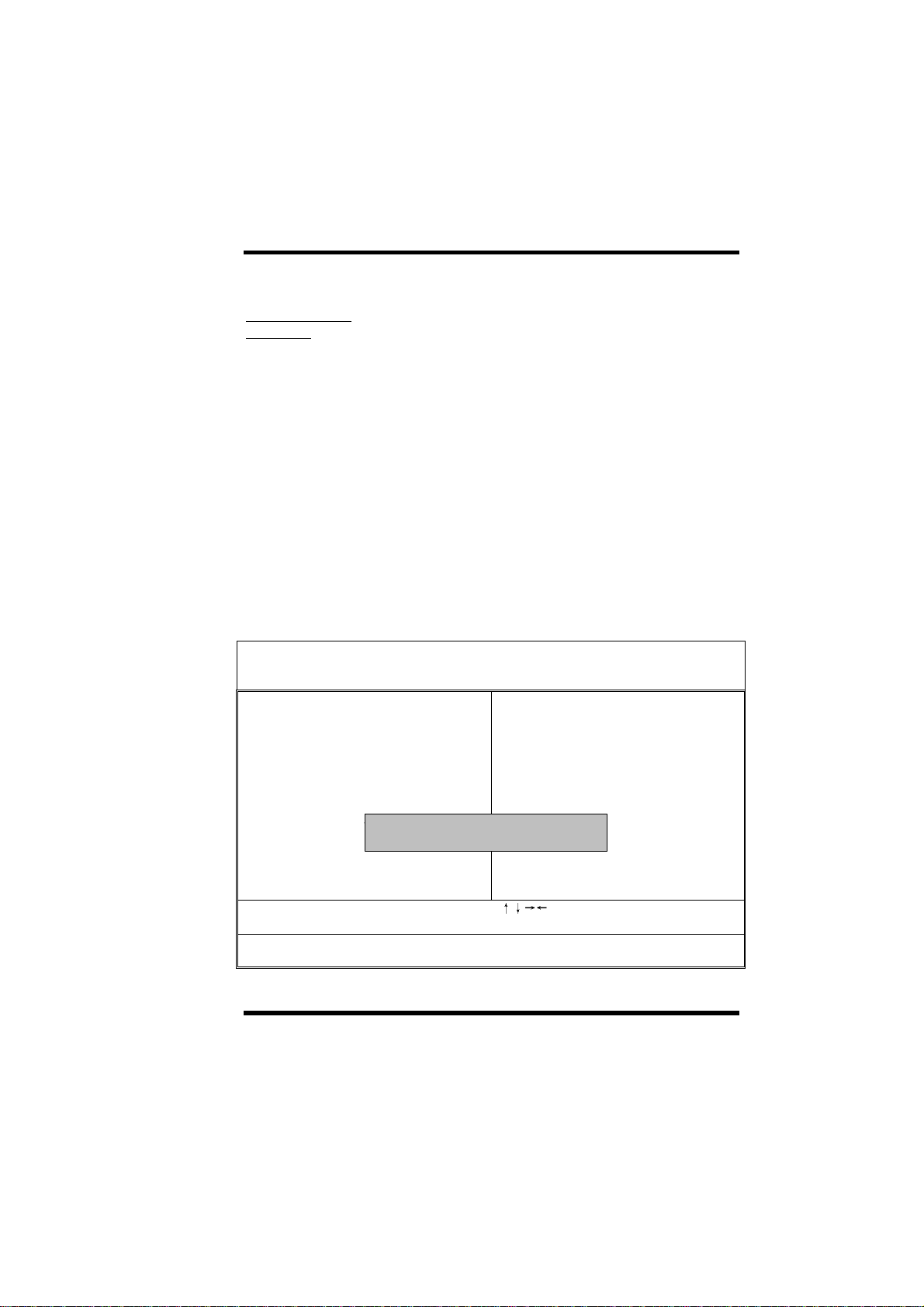
3.7 Load Setup Defaults
ROM PCI/ISA BIOS(00000006)
CMOS SETUP UTILITY
AWARD SOFTWARE, INC.
STANDARD CMOS SETUP INTEGRATED PERIPHERALS
BIOS FEATURES SETUP PASSWORD SETTING
CHIPSET FEATURES SETUP IDE HDD AUTO DETECTION
POWER MANAGEMENT SETUP SAVE & EXIT SETUP
PNP/PCI CONFIGURATION EXIT WITHOUT SAVING
LOAD SETUP DEFAULTS
LOAD TURBO DEFAULTS
Esc: Quit
F10:Save & Exit Setup (Shift)F2:Change Color
Load SETUP Defaults (Y/N)? N
:Select Item
3-30 ILA USER’S MANUAL
Page 57
III. CMOS SETUP UTILITY
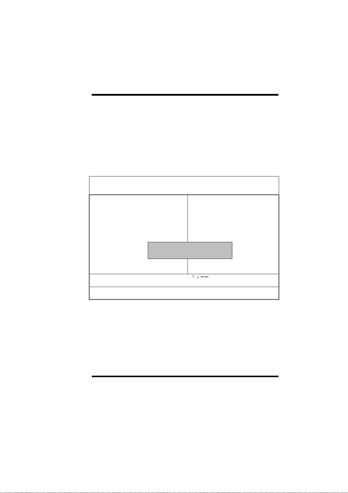
This option allows you load BIOS optimized settings for optimum system
performance. We recommend you to use the Optimal settings if your system
has large memory size and fully loading with add-on cards.
To load Setup Default, press Y key to confirm the operation when you see the
above display.
3-8 Load Turbo Defaults
ROM PCI/ISA BIOS(00000006)
CMOS SETUP UTILITY
AWARD SOFTWARE, INC.
STANDARD CMOS SETUP INTEGRATED PERIPHERALS
BIOS FEATURES SETUP PASSWORD SETTING
CHIPSET FEATURES SETUP IDE HDD AUTO DETECTION
POWER MANAGEMENT SETUP SAVE & EXIT SETUP
PNP/PCI CONFIGURATION EXIT WITHOUT SAVING
LOAD SETUP DEFAULTS
LOAD TURBO DEFAULTS
Esc: Quit
F10:Save & Exit Setup (Shift)F2:Change Color
Load Turbo Defaults (Y/N)? N
:Select Item
This option provides better performance than optimal setup values. Load the
turbo values if you have light system loading, that is, few add-on cards and
memories.
If your system has heavy loading (more add-on cards and memories), you
may manually set the parameters in the "Chipset Features Setup" to get
proper setting to get the best system performance. Before changing any
settings in the "Chipset Features Setup", be sure that you understand the
functions of every item.
ILA USER’S MANUAL 3-
31
Page 58
III. CMOS SETUP UTILITY
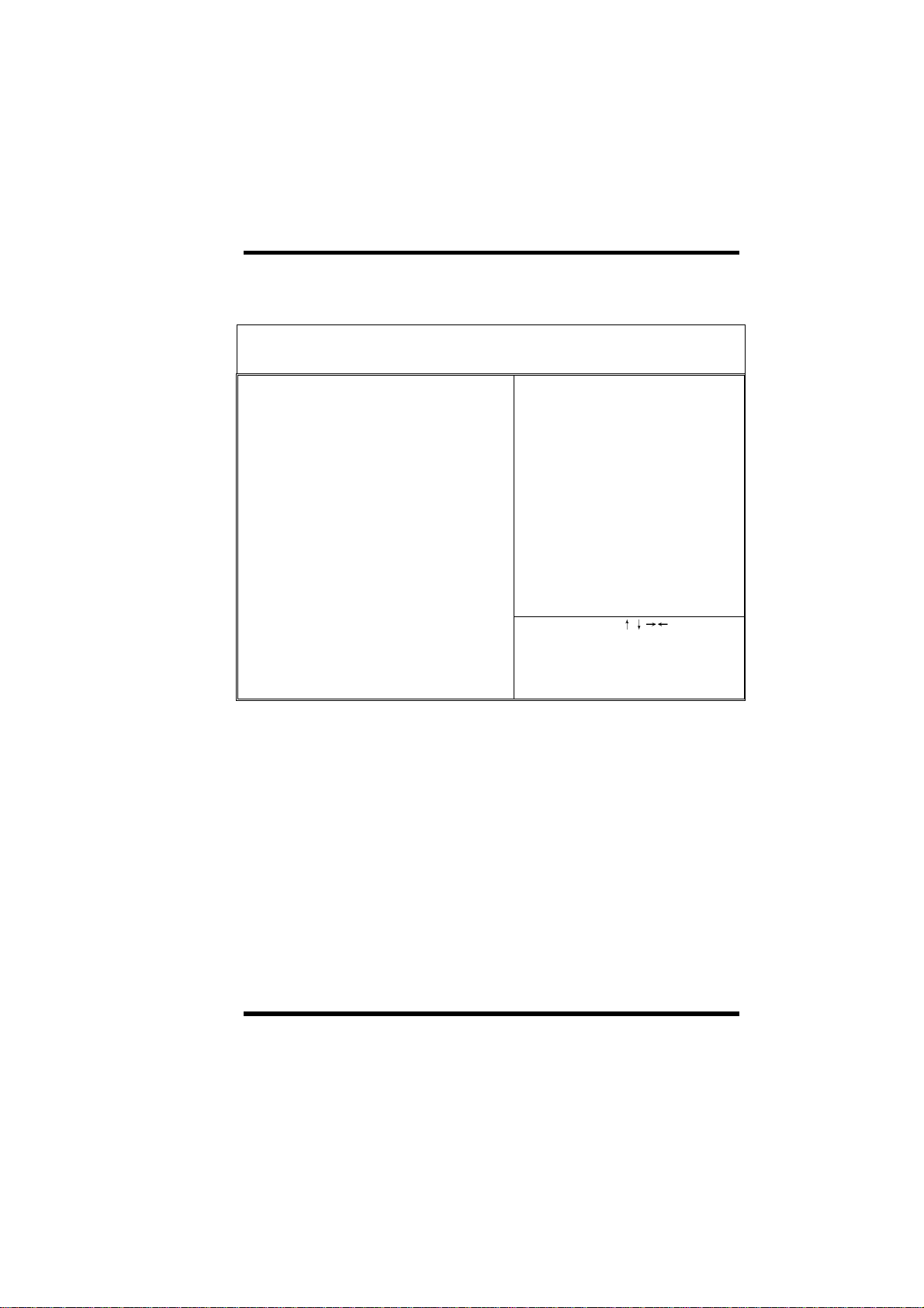
3-9 Integrated Peripherals
ROM PCI/ISA BIOS(00000009)
INTEGRATED PERIPHERALS
AWARD SOFTWARE, INC.
IDE HDD Block Mode : Enabled Onboard Serial1 Port 2 : Auto
IDE Primary Master PIO : Auto Onboard UART 2 Mode : Standard
IDE Primary Slave PIO : Auto
IDE Secondary Master PIO : Auto Onboard Parallel Port : 378/IRQ7
IDE Secondary Slave PIO : Auto Parallel Port Mode :SPP
IDE Primary Master UDMA : Auto
IDE Primary Slave UDMA : Auto
IDE Secondary Master UDMA : Auto
IDE Secondary Slave UDMA : Auto
On-Chip Primary PCI IDE : Enabled
On-Chip Secondary PCI IDE : Enabled
USB Legacy Support : Disabled
USB IRQ Released : No
Flash/Upgrade BIOS : Enabled
Onboard Sound Chip : Enabled
ESC: Quit
KB Power ON (Ctrl-F1) : Disabled F1: Help PU/PD/+/-: Modify
PS2 Mouse Power ON : Disabled F5: Old Values (Shift) F2:Color
Onboard FDC Controller : Enabled F6: Load Setup Defaults
Onboard Serial1 Port 1 : Auto F7: Load Turbo Defaults
:Select Item
This option allows you to configure the I/O features.
3-32 ILA USER’S MANUAL
Page 59

Ø IDE HDD Block Mode
III. CMOS SETUP UTILITY
IDE HDD Block
Mode:
- Enabled
- Disabled
This BIOS supports the enhanced IDE specification
and allow multiple sectors access in a time when
read/write. If set this item to disabled, IDE runs in
single sector access.
Ø IDE Primary Master PIO
Ø IDE Primary Slave PIO
Ø IDE Secondary Master PIO
Ø IDE Secondary Slave PIO
IDE
Primary/Secondary
Master/Secondary
PIO:
- Auto
- Mode 1
- Mode 2
- Mode 3
- Mode 4
Set these items to Auto to auto-detect the HDD
speed. The PIO mode specifies the data transfer rate
of HDD.
IDE HDD Mode Transfer Rate
Mode 0 3.3MB/s
Mode 1 5.2MB/s
Mode 2 8.3MB/s
Mode 3 11.1MB/s
Mode 4 16.6MB/s.
Set to slower mode if your hard disk performance
becomes unstable.
Default: Enabled
Default: Auto
Ø IDE Primary Master UDMA
Ø IDE Primary Slave UDMA
Ø IDE Secondary Master UDMA
Ø IDE Secondary Slave UDMA
ILA USER’S MANUAL 3-
33
Page 60

III. CMOS SETUP UTILITY
IDE
Primary/Secondary
Master/Slave UDMA:
- Auto
- Disabled
These items allows you to set the Ultra DMA/33 mode
supported by the IDE hard disk drive installed in your
system.
Ø On-Chip Primary PCI IDE
Ø On-Chip Secondary PCI IDE
On-Chip
Primary/Secondary
PCI IDE:
- Enabled
- Disabled
To enable or disable the IDE device connected to the
Primary/Secondary IDE connector.
Ø USB Legacy Support
USB Legacy Support:
- Enabled
- Disabled
This BIOS simulates USB keyboard in legacy mode,
which means during POST or under operating
system, you can use a USB keyboard without loading
USB driver. Note you can not use both USB driver
and USB legacy keyboard at the same time. Set
disabled if you have USB driver in the operating
system.
Default: Auto
Default: Enabled
Default: Disabled
Ø USB IRQ Released
USB IRQ Released:
- Yes
- No
This item allows you to release USB controller IRQ if
you do not have any USB device or your system IRQ
are not enough for add-on cards allocation.
Default: No
3-34 ILA USER’S MANUAL
Page 61

Ø Flash/Upgrade BIOS
III. CMOS SETUP UTILITY
Flash/Upgrade BIOS:
- Enabled
- Disabled
This item allows you to protect your mainboard BIOS
being flashed/upgraded by MAXFLASH.EXE flash
utility if you set this item disabled.
You can specify the BIOS password to avoid that
someone can change your setting.
Ø Onboard Sound Chip
Onboard Sound
Chip:
- Enabled
- Disabled
This item allows you to enabled or disabled the OPTi
sound chip function on the mainboard.
Ø KB Power ON (Ctrl-F1)
KB Power ON:
- Enabled
- Disabled
This item allows you to enable or disable the
keyboard power on function.
Press “Ctrl-F1” to power on system after setting this
item to enabled.
Ø PS2 Mouse Power ON
Default: Enabled
Default: Enabled
Default: Disabled
PS2 Mouse Power
ON:
- Enabled
- Disabled
ILA USER’S MANUAL 3-
This item allows you to enable or disable the mouse
power on function.
Double click on the system PS2 mouse button to
power on system after setting this item to enabled.
Default: Enabled
35
Page 62

III. CMOS SETUP UTILITY
Ø Onboard FDC Controller
Onboard FDC
Controller:
- Enabled
- Disabled
To enable or disable the onboard floppy disk
controller. Set to disabled if you want to use a
separate floppy disk controller card.
Ø Onboard Serial Port 1
Ø Onboard Serial Port 2
Onboard Serial Port
1 & 2:
- Auto
- 3F8/IRQ4
- 2F8/IRQ3
- 3E8/IRQ4
- 2E8/IRQ3
- Disabled
This item allows you to select the I/O port and IRQ
used by the onboard serial ports.
Ø Onboard UART Mode
Onboard UART
Mode:
- Standard
- IrDA
- ASKIR
This item is selectable only when the onboard serial
port 2 is enabled. The available mode selections for
the serial port 2 are Standard, IrDA, and ASKIR.
Standard: Configures serial port as normal mode.
IrDA: Set to this setting if there is an infrared device
connected on the onboard IrDA connector. The
maximum baud rate of this setting is: 115K baud.
ASKIR: Set to this setting if there is an infrared device
connected on the onboard IrDA connector. The
maximum baud rate of this setting is: 19.2K baud.
Default: Enabled
Default: Onboard Serial Port 1=> Auto
Onboard Serial Port 2=> Auto
Default: Standard
3-36 ILA USER’S MANUAL
Page 63

Ø Onboard Parallel Port
III. CMOS SETUP UTILITY
Onboard Parallel
Port:
- 3BC/IRQ7
- 378/IRQ7
- 278/IRQ7
- Disabled
This item controls the onboard parallel port address
and interrupt.
Ø Parallel Port Mode
Parallel Port Mode:
- SPP
- EPP
- ECP
- ECP + EPP
This item allows you to set the parallel port mode.
1. SPP (Standard Parallel Port): IBM AT and PS/2
compatible mode
2. EPP (Enhanced Parallel Port): To enhances the
parallel port by directly write/read data to/from
parallel port without latch.
3. ECP (Extended Parallel Port): ECP supports DMA
and RLE (Run Length Encoded) compression and
decompression.
Ø ECP Mode Use DMA
Default: 378/IRQ7
Default: SPP
ECP Mode Use DMA:
- 3
- 1
ILA USER’S MANUAL 3-
This item displayed when select the ECP mode above
for the parallel port. You can set the DMA channel of
ECP mode.
Default: 3
37
Page 64

III. CMOS SETUP UTILITY
3-10 Password Setting
Password prevents unauthorized use of your computer. If you set a password,
the system prompts for the correct password before boot or access to Setup,
the steps as follows,
1. Highlight the item Password Setting on the main menu and press ENTER.
2. The password dialog box will appear.
3. If you are installing a new password, carefully type in the password.
Press ENTER after you have typed in the password. If you are deleting a
password that is already installed just press ENTER when the password
dialog box appears.
4. The system will ask you to confirm the new password by asking you to
type it in a second time. Carefully type the password again and press
ENTER, or just press ENTER if you are deleting a password that is
already installed.
5. If you typed the password correctly, the password will be installed.
[Note]
If you forget your password, or you want to cancel your password, you can do
the steps as the following,
(1) Password forgotten:
i> Turn off the system
ii> Short JP1 at Pin 2-3 for a few seconds to clear CMOS.
iii> Set the JP1 back to Pin 1-2.
iv> Power on the system.
(2) Clear Password:
Clear your password by key-in the password you installed before,
then go to PASSWORD SETTING to press ENTER twice.
3-38 ILA USER’S MANUAL
Page 65

III. CMOS SETUP UTILITY
3-11IDE HDD Auto Detection
This item automatically detects and installs any hard disk drives installed on
the primary and secondary IDE channel. Most modern drives can be detected.
If you are using a very old drive that can’t be detected, you can install it
manually using the Standard CMOS Setup option. Setup will check for two
devices on the primary IDE channel and then two devices on the secondary
IDE channel. At each device, the system will flash an N in the dialog box.
Press Enter to skip the device and proceed to the next device. Press Y, then
Enter to tell the system to accept the BIOS auto-detected device type.
3-12 Save & Exit Setup
Highlight this item and press ENTER to save the changes that you have made
in the setup utility and exit the setup program. When the Save and Exit dialog
box appears, press Y to save and exit, or press N to return to the setup main
menu.
3-13 Exit without Saving
Use this option to exit Setup Utility without saving the CMOS value changes.
3-39 ILA USER’S MANUAL
Page 66

SECTION 4.
BIOS/SOFTWARE UTILITY
4-1 Flash Utility MAXFLASH.EXE
This section tells you a step-by-step procedure on how to use the flash utility,
“maxflash.exe”, upgrade your mainboard BIOS.
To upgrade your motherboard BIOS, please follow the following:
1. For Win95 system, press F8 before Win95 boot-up and select “Safe
mode command prompt only”.
For Non-Win95 system, boot-up the system into DOS prompt with a
bootable floppy disk.
!!!DO NOT load any memory manager like EMM386.EXE,
QEMM386.EXE under config.sys.!!!
2. Run A: >maxflash biosfile.bin
3. After loading the new BIOS code, the utility will prompt you to save
original BIOS code into your HDD or floppy. Please press "Y" to
store it as "BIOS.OLD".
4. After the old BIOS has been successfully saved, press "Y" to replace BIOS.
5. After the flashing process, reboot the system by turn off the power.
!!! DO NOT TURN OFF THE POWER DURING THE FLASHING
PROCESS. !!!
6. Press "DEL" key to enter BIOS setup during POST. Reload the
SETUP DEFAULT" and reconfigure other items as your previous
"BIOS
setting
7. Then save and exit.
4-1 ILA USER’S MANUAL
Page 67

IV.BIOS/SOFTWARE UTILITY
4-2 BIOS Flash/Upgrade Protection
This mainboard supports BIOS Flash/Upgrade protection which allows you
protect your system BIOS being flashed by flash utility. We suggest you use
this feature with Password Setting in BIOS to prevent your BIOS being flashed
by flash utility.
To active the BIOS Flash/Upgrade protection, follow the steps below:
1. When the system boot up at POST (Power On Self- Test), press <Del> key
to enter BIOS Setup Utility.
2. Set the “Flash/Upgrade BIOS” item in the “Integrated Peripherals” to
Disabled.
3. Save the changes and exit Setup Utility.
4-3 Remove Question Marks “?” in Win95
Device Manager
Since some of Intel 440BX/LX/EX latest technologies, like “ACPI”, “USB” &
“Ultra DMA/33”, are so new, Win95 did not support them on Aug. of 1995
which is the moment Win'95 formal released.
To solve this problem, please use the Win95 patch utility – Mpatch.exe.
After running the utility, you should select both “Chipset” & “USB controller”
under “Choice” for full installation.
4-4 Install Bus Master IDE (Ultra DMA/33)
Driver
The Bus Master IDE (Ultra DMA/33) driver is available in the bundled CD title.
You may run IDE\setup.exe directly to install the driver.
After installation, you will see following devices under Win95 Device Manager:
--- Hard Disk Controllers
Intel 82371AB PCI Bus Master IDE Controller
Primary Bus Master IDE Controller
Secondary Bus Master IDE Controller
4-2 USER’S MANUAL
Page 68

SECTION 5.
AUDIO DRIVER/UTILITY
The onboard OPTi 933 audio adapter has four sets of audio drivers for
different operation system. All drivers can be found in the bundle CD title.
Drivers Overview:
- Microsoft Windows 95/ Windows 98
- Microsoft Windows NT 3.50/3.51/4.00
- Microsoft Windows 3.1
- OS/2 2.1 / 3.0
5-1 Windows95/98 Driver Installation
Driver files location:
Windows 95/98 audio driver for English version: \Audio\OPTI\933\win95
Procedure:
1. Update Device Driver Wizard
When windows95/98 boot up, the “Update Device Driver Wizard” will
appear. Please select “Next” to complete the Audio driver installation.
2. Select Location
If Windows can not find the proper driver location, please select “Other
Location…” for the right driver location.
Type in the driver location: D: \Audio\OPTI\933\win95 (assuming your
CD-ROM disc drive is in drive D), then select OK.
3. Copy Files From
Windows 95 will then ask you confirm the driver location, please type
in D: \Audio\OPTI\933\win95 (assuming your CD-ROM disc drive is in
the drive D).
ILA USER’S MANUAL
5-1
Page 69

V.AUDIO DRIVER/UTILITY
After Windows 95 has finished copying all necessary files, please select
Yes to restart your computer.
After finishing the driver installation, the sound devices will be added
under Win95 Device Manager.
5-2 Windows NT Driver Installation
Driver Files Location
Windows NT audio driver: \ Audio \ OPTI \ 933 \ WIN-NT
Procedure:
1. Click Start---Setting---Control Panel
2. Double Click Multimedia Icon
3. Click Device---Add
4. Select Unlisted or Updated Driver then click OK
5. Input Driver Path <CD-ROM Driver>: \ Audio \ OPTI\933\WIN_NT
6. Select OPTi 82c933 then click OK
7. Restart your system, Driver Installation Finished.
5-3 DOS/Windows 3.1 Driver Installation
Driver Files Location
Windows 3.1 audio driver: \ Audio \ OPTI \ 933 \ dos_w31
Procedure:
Run <CD-ROM Driver>: \ Audio \ OPTI \ 933 \ dos-w31 \ setup.exe
5-4 OS/2 Driver Installation
Driver Files Location
OS/2 audio driver: \ Audio \ OPTI \ 933 \ OS2
Procedure:
Run <CD-ROM Driver>: \ Audio \ OPTI \ 933 \ OS2 \ minstall.exe
ILA USER’S MANUAL
5-2
 Loading...