

Page 1

EUPA
AP0
Motherboard
User's Manual
Model : AP0
Manual version : English, version 1.1
Release Date : June 22, 1999
Page 2

Copyright
Copyright 1999 by this company. All rights reserved.
No part of this publication may be reproduced, transmitted, transcribed,
stored in a retrieval system, or translated into any language in any form or by
any means, electronic, mechanical, magnetic, optical, manual or otherwise,
without the prior written consent of the copyright holders.
User’s Notice
The contents of this publication are subject to change. This company reserves
the right to alter the contents of this publication at any time and without
notice. The contents of this publication may contain inaccuracies or
typographical errors and is supplied for informational use only.
Intel and Pentium are registered trademarks of Intel Corporation.
OS/2 and IBM are registered trademarks of International Business Machines.
Windows and MS-DOS are registered trademarks of Microsoft Corporation.
AWARD is a registered trademark of Award Software Inc.
Other brand, corporate, and product names may or may not be registered
trademarks or copyright of their respective companies.
FCC & DOC Compliance
Federal Communications Commission Statement
This device complies with FCC Rules Part 15. Operation is subject to the
following two conditions:
II
Page 3

² This device may not cause harmful interference, and
² This device must accept any interference received, including
interference that may cause undesired operation.
This equipment has been tested and found to comply with the limits for a
Class B digital device, pursuant to Part 15 of the FCC Rules. These limits are
designed to provide reasonable protection against harmful interference in a
residential installation. This equipment generates, uses and can radiate radio
frequency energy and, if not installed and used in accordance with the
manufacturer
communication. However, there is no guarantee that interference will not
occur in a particular installation. If this equipment does cause harmful
interference to radio or television reception, which can be determined by
turning the equipment off and on, the user is encouraged to try to correct the
interference by one or more of the following measures:
² Re-orient or relocate the receiving antenna.
² Increase the separation between the equipment and the receiver.
² Connect the equipment to an outlet on a circuit different from that to
which the receiver is connected.
² Consult the dealer or an experienced radio/TV technician for help.
Warning! The use of shielded cables for the connection of the monitor to
the graphics card is required to assure compliance with FCC regulations
Changes or modifications to this authority to operate this equipment.
III
Page 4

CONTENTS
SECTION 1: PRODUCT INFORMATION
1-1 Manual Features………………………….…...1-1
1-2 Package Check List………………………… 1-1
1-3 Mainboard Specification...…….…………….1-2
1-4 Mainboard Layout ……………………………1-5
SECTION 2: HARDWARE INSTALLATION
2-1 Jumper Settings..........................................2-1
2-1.1 CMOS Clear Setting ………..............………… … ……........2-1
2-1.2 CPU Type Setting …………………......................……..........2-2
2-2 Connectors ……….……....……………...........2-5
IV
2-2.1 Panel Connector……….…...….…………………………….....2-5
2-2.2 Power Connector…………....………………………………....2-5
2-2.3 Fan Connectors…….……..…….….....….…………………....2-6
2-2.4 PS/2 Mouse Connector…………..…………………………....2-7
2-2.5 Keyboard Connector….………..…………………………….....2-7
2-2.6 USB Device Connector……..……………………………….....2-8
2-2.7 Serial Device(COM1/COM2) Connectors……...…....….......2-8
2-2.8 Printer Connector.….….….….…….….…....….….................2-9
2-2.9 Floppy Drive Connector…….….….……......................…......2-9
2-2.10 IDE Hard Disk and CD-ROM Connector..…….…….……..2-10
2-2.11 IrDA Connector…….….………………………........….….....2-11
2-2.12 Game/Audio Connector ..……………...…....……….......…2-11
Page 5

2-2.13 Wake On LAN Connector….….…..........…....…....…..…2-12
2-3 System Memory Installation .......………...2-13
2-3.1 Type ..........................................................….........….…2-13
2-3.2 Speed ..……….……………………………………………2-13
2-3.3 Buffered and Non-buffered ..……..........….....….…...…2-14
2-3.4 2-clock and 4-clock Signal….……..….…...……….....…2-14
2-3.5 Parity and Non-parity………....……...………….........…2-14
2-3.6 Memory Auto detection by BIOS …....….………………2-15
2-3.7 Suggested SDRAM combination ….........…...…………2-15
SECTION 3: CMOS SETUP UTILITY
3-1 BIOS Setup Main Menu..............................3-1
3-2 Standard CMOS Setup...............................3-2
3-3 BIOS Features Setup.................................3-5
3-4 Chipset Features Setup...........................3-10
3-5 Power Management Setup.......................3-14
3-6 PNP/PCI Configuration Setup.................3-19
3-7 Load BIOS Defaults..................................3-22
3-8 Load Setup Defaults................................3-23
3-9 W83783S Hardware Monitor………….……3-24
3-10 Integrated Peripherals.............................3-26
3-11 Password Setting………................…..……3-32
3-12 IDE HDD Auto Detection…....….…..………3-33
3-13 Save & Exit Setup………..........….….….…3-33
3-14 Exit without Saving……..……......….….….3-33
V
Page 6

SECTION 4: Audio/SOFTWARE UTILITY
4-1 Dos Installation…………………………………4-1
4-2 Win 95/98 Installation…………………………..4-1
4-3 Window NT 4.0 Installation……………………4-3
VI
Page 7

SECTION 1.
PRODUCT INFORMATION
Thanks for purchasing AP0 motherboard.
This user’ s manual contains all the information and features that show you
how to use the AP0 motherboard. Please take a moment to familiarize
yourself with the design and organization of this manual.
1-1 Manual Features
This manual is divided into the following four sections:
Section 1: Product Information
A brief overview of what comes in the motherboard package, the motherboard
layout and the specification it appears.
Section 2: Hardware Installation
Tell you the usage of the motherboard jumpers and the connectors.
Section 3: CMOS Setup Utility
A summary of the motherboard CMOS (BIOS) Setting.
Section 4: BIOS/Software Utility
Introduction of some useful motherboard’ s BIOS/Software utility.
1-2 Package Check List
This AP0 motherboard package contains the following items. Please
inspect the package contents and confirm that everything is there. If
anything is missing or damaged, call your vendor for instructions before
operating.
AP0 USER’S MANUAL 1-1
Page 8

I. PRODUCT INFORMATION
The package includes:
l One AP0 Motherboard
l One Floppy Interface Cable
l One IDE Interface Cable
l One CD Title including Bus Master IDE Driver and Utilities
l One User’ s Manual
1-3 Motherboard Specification
Form Factor -MICRO-ATX form factor
Board Size -193mm x 244mm
CPU -Supports Socket PGA370-Celeron CPU
System Memory -DIMM 168-pin x 3, SDRAM maximum 768MB
-Support ECC (1-bit error code correct) function
Chipset -Ali Aladdin Pro II Chipset
System Bus/FSB -66/100MHz
-75/83/103/105/110/112/115/120/124/133/140/150MHz
(Available for over-clocking)
Expansion Slots -1 x AGP bus / 3 x PCI bus / 1 x ISA bus
Serial Port -Two serial ports UART 16550 compatible
Parallel Port One parallel port supports:
-SPP-standard parallel port
-EPP-enhanced parallel port
-ECP-extended capabilities port
Floppy Interface Support drivers inches/format with:
-3.5 inches-720KB/1.44MB/2.88MB
-5.25 inches-360KB/1.2MB
IDE Interface -Dual IDE interface support up to four IDE devices
1-2 AP0 USER’S MANUAL
Page 9

I. PRODUCT INFORMATION
USB Interface -Two USB ports supported
-USB legacy keyboard function supported
PS/2 Mouse -PS/2 mouse supported by connector onboard
PS/2 Keyboard -PS/2 keyboard supported by connector onboard
Sound Integrated C-MEDIA 8338 sound controller compatible
with:
-Sound Blaster Pro
-Adlib
-Microsoft windows system
RTC and Battery -Integrated Ali M5819P RTC chipset
-Lithium (CR-2032) battery
Power On -Panel switch power on
-Keyboard power on
Wake-Up -Modem ring wake up
-LAN wake up
-RTC Alarm Function
Hardware
Monitor
Power
Connector
-Fan speed monitor-Two fan connectors, warning when
CPU fan, housing fan or system fan is malfunction
-Voltage monitor-Warning when system voltage (5V,
12V, 3.3V, VCORE) are abnormal
-CPU and system thermal monitor-Warning when CPU
and system temperature is higher than a predefined
value
-Supports ATX (20-pin) power connector
AP0 USER’S MANUAL 1-3
Page 10

I. PRODUCT INFORMATION
BIOS -Award BIOS
-Year 2000 Compliance
-PCI 2.1 Compliance
-PnP BIOS v1.0a Compliance
-APM v1.2 Compliance
-DMI 2.0 compliance
-Flash/Upgrade BIOS protection
-Supports ACPI (Advanced Configuration and Power
Interface) and OS Directed Power Management
-Supports SOFT power
-Virus warning supported
-Floppy drive swapping function supported
LED Indicator -System power LED
-HDD activity LED
Other -Support two FAN connectors
1-4 AP0 USER’S MANUAL
Page 11
I. PRODUCT INFORMATION
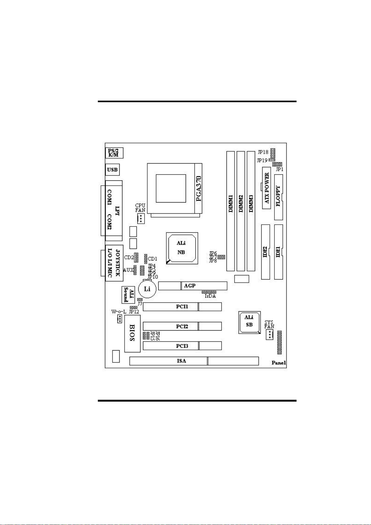
1-4 Motherboard Layout
AP0 USER’S MANUAL 1-5
Page 12

I. PRODUCT INFORMATION
Jumpers
1. JP1
2. JP6~8,JP19
3. JP18
4. JP12
5. JP15, JP16
6. J7
Expansion Sockets
1. DIMM 1
2. DIMM 2
3. DIMM 3
Expansion Slots
1. CPU
2. ISA Slot
3. PCI Slot 1 to Slot 3
4. AGP
Connectors
1. PS/2 KB
2. PS/2 Mouse
3. USB
4. COM1/COM2
5. PRINTER
6. JOYSTICK
7. CD1/CD2
8. SOUND
9. ATX POWER
Select VIO voltage (reserved)
Select CPU External Speed
Select CPU Speed Ratio
Clear CMOS (Real Time Clock)
Select ROM BIOS Type (reserved)
Select Sound ENABLE/DISABLE
Support 168-pin DIMM Memory
Support 168-pin DIMM Memory
Support 168-pin DIMM Memory
Socket PGA370-Celeron CPU
16-bit ISA Bus Expansion Slot
32-bit PCI Bus Expansion Slot
Accelerate Graphic Port
PS/2 Keyboard Connector (6-pin female)
PS/2 Mouse Connector (6-pin female)
Universal Serial Bus Port 1 and Port 2
(two 4-pin female)
Serial Port 1 / Serial Port 2 (two 9-pin female)
Printer (Parallel) Port Connector (25-pin female)
Joystick Connector (15-pin female)
CD Audio Line in (4-pin male )
Sound port Connector (Line out / Line in / MIC in)
ATX Motherboard Power Connector (20-pin block)
1-6 AP0 USER’S MANUAL
Page 13

I. PRODUCT INFORMATION
10. CPUFAN
11. CHAFAN
12. Floppy
13. Primary IDE
14. Secondary IDE
15. IR
16. Wake on LAN
17. Panel:
- SPEAKER
- RESET
- SMI
- HDD LED
- PWR ON
- PWR LED
- KBLCK
CPU Fan Connector (3 pins)
Chassis Fan Connector (3 pins)
Floppy Drive Connector (34 pins)
Primary IDE Connector (40 pins)
Secondary IDE Connector (40 pins)
Infrared Port Connector (5 pins)
LAN wake up connector
Chassis Speaker Connector (4 pins)
Reset Switch Connector (2 pins)
SMI Connector (2 pins reserved)
HDD LED Connector (2 pins)
ATX Power Switch Connector (2 pins)
ATX Power LED Connector (3 pins)
Keyboard Lock Switch Connector (2 pins)
AP0 USER’S MANUAL 1-7
Page 14
SECTION 2.
HARDWARE INSTALLATION
This section gives you a step-by-step procedure on how to install your
system. Follow each section accordingly.
2-1 Jumper Settings
Please refer the following figures for the locations of the jumpers on the
mainboard.
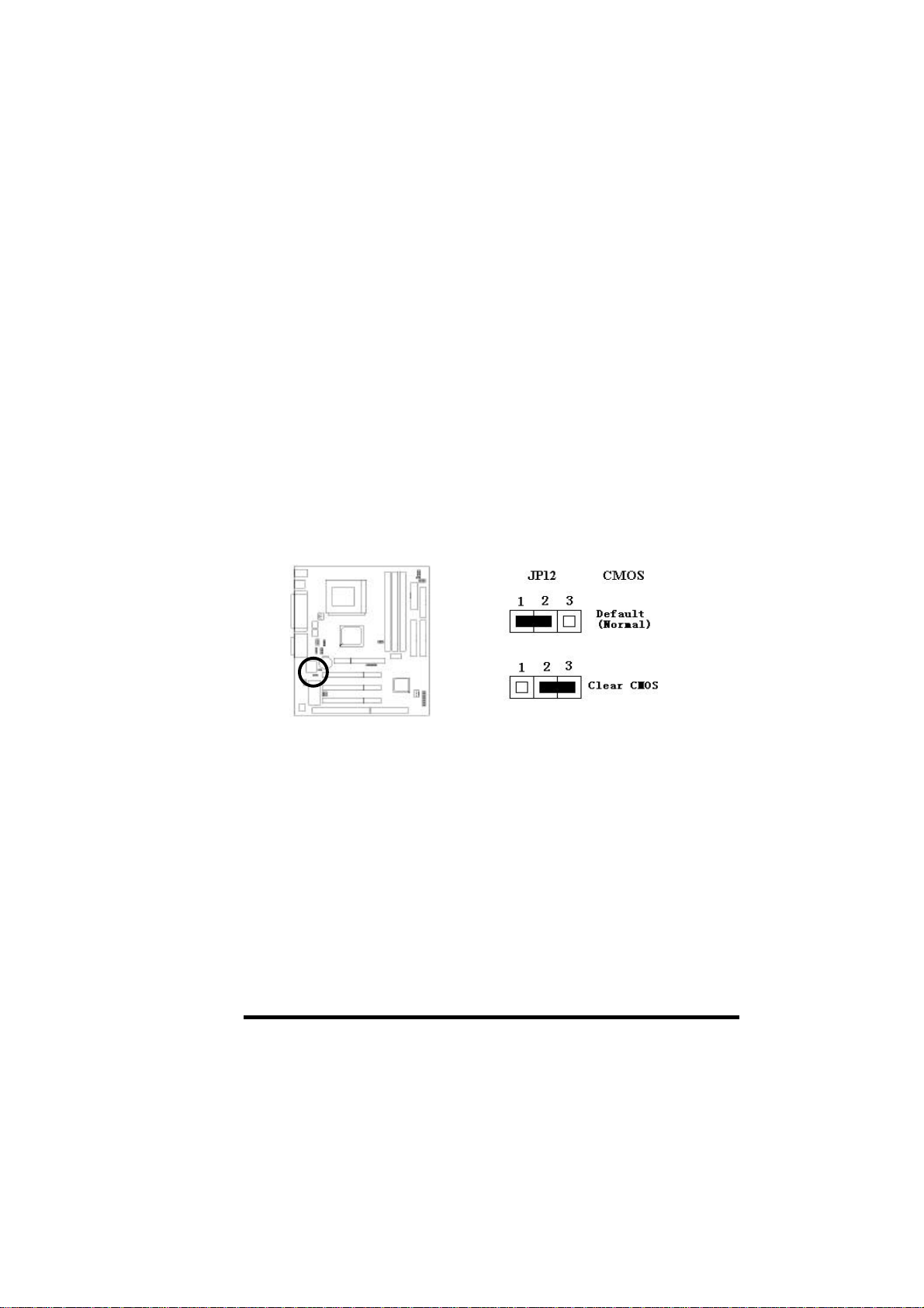
2-1.1 CMOS Clear Setting
To clear CMOS, please follow the steps below:
1. Power off the system and unplug the chassis AC power cord.
2. Short JP12 at pin 2-3 for few seconds.
3. Set JP12 back to its Normal position at pin 1-2.
4. Plug the AC power cord to the chassis.
5. Power on the system and load the BIOS setup default.
AP0 USER'S MANUAL 2-1
Page 15
II.HARDWARE INSTALLATION
2-1.2 CPU Type Setting
Static Precautions
Static electricity can be a serious danger to the electronic components on
this motherboard. To avoid damage caused by electrostatic discharge,
observe the following precautions:
-Don’ t removes the motherboard from its anti-static packaging until you
are ready to install it into a computer case.
-Before you handle the motherboard in any way, touch a grounded, antistatic surface, such as an unpainted portion of the system chassis, for a
few seconds to discharge any built-up static electricity.
-Handle add-in cards and modules by the edges or mounting bracket.
Installing the CPU
Warning: User of a CPU Cooling Fan is required to prevent CPU overheating. The
Fan should be installed first before inserting the CPU into its socket.
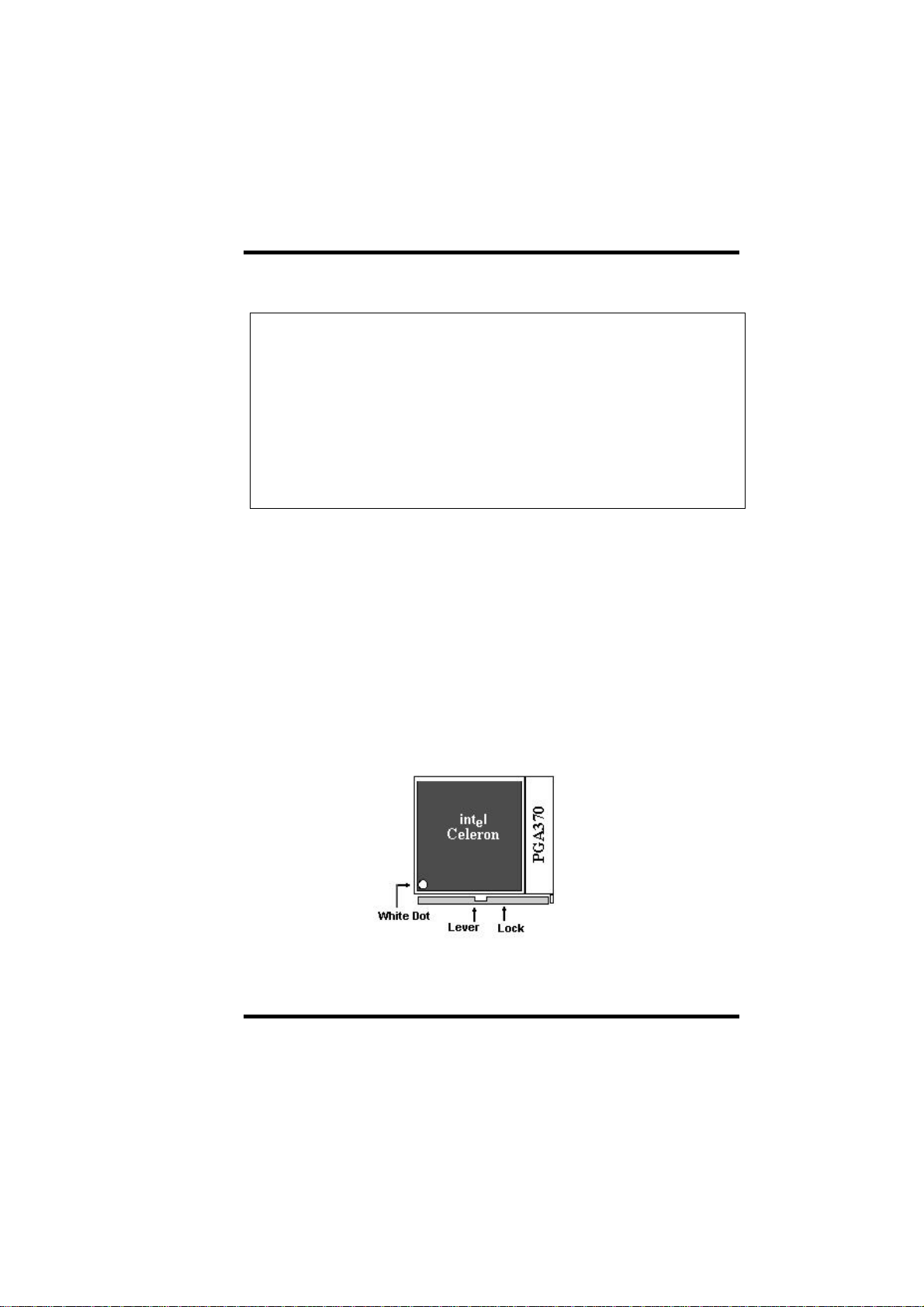
1.Locate the ZIF (Zero Insertion Force) PGA370. This socket supports Celeron CPUs.
2.First open the socket by pulling the lever sideways, then upwards. Notice how the
level locks in place when pressed all the way down.
3.The CPU must be inserted with the correct orientation. One corner of the CPU has a
“Notch” and looks different that the other three. This corner is also missing a pin
unlike the other three and is marked with a white dot on top of the CPU. Align this
corner towards the end of the lever as shown in the figure below. Insert the CPU,
press it down, and close the lever until it locks into place
2-2 AP0 USER’S MANUAL
Page 16
II.HARDWARE INSTALLATION
CPU Setting
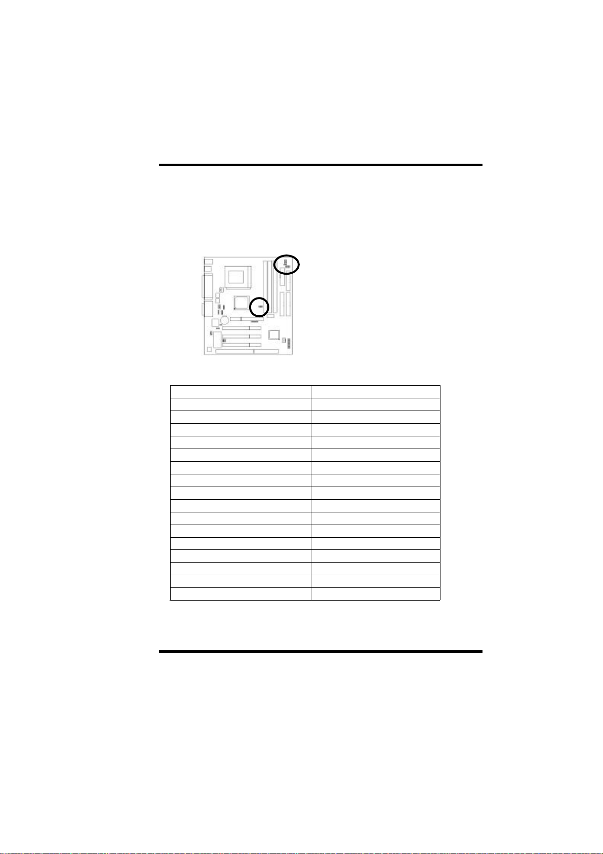
After installing the CPU, you must set the clock selection jumpers to match the
frequency of the CPU. Find the jumpers labeled JP19 and JP6~8. Set the jumpers
according to the figure below and table for CPU frequency.
JP19
JP6, JP7, JP8
JP6/JP7/JP8/JP19: CPU External Frequency Setup Table
JP6 JP7 JP8 JP19 CPU (MHz)
S O O S 66
S S O S 75
S O S S 83
S O O O 100
S S S O 103
O O O S 105
O O S S 110
S S O O 112
O S O S 115
O S S S 120
S S S S 124
O O S O 124
S O S O 133
O O O O 133
O S S O 140
O S O O 150
S: short, O: open
AP0 USER'S MANUAL 2-3
Page 17

II.HARDWARE INSTALLATION
This motherboard also supports CPU over-clocking by adjusting the CPU Clock
Frequency and CPU Clock Ratio.
System Frequency = CPU Clock Ratio * CPU Clock Frequency
The available settings are:
- CPU Clock Frequency
66/75/83/100/103/105/110/112/115/120/ 124/133/140/150MHz
- CPU Clock Ratio
1.5x/2x/2.5x/3x/3.5x/4x/4.5x/5x/5.5x/6x/6.5x/7x/7.5x/8x
JP18: CPU Clock Radio
JP18(1) JP18(2) JP18(3) JP18(4) Ratio
O O S O 1.5X
S S S S 2X
O S S S 2.5X
S S O S 3X
O S O S 3.5X
S S S O 4X
O S S O 4.5X
S S O O 5X
O S O O 5.5X
S O S S 6X
O O S S 6.5X
S O O S 7X
O O O S 7.5X
S O S O 8X
S O O O Reserved
S: short, O: open
Warning: Normally, Aladdin Pro II Chipset supports 66MHz/100MHz CPU Clock
Frequency, the other CPU Clock Frequency are available only for internal test or enduser over-clocking testing, which may cause your system unstable or serious damage.
2-4 AP0 USER’S MANUAL
Page 18
II.HARDWARE INSTALLATION
2-2 Connectors
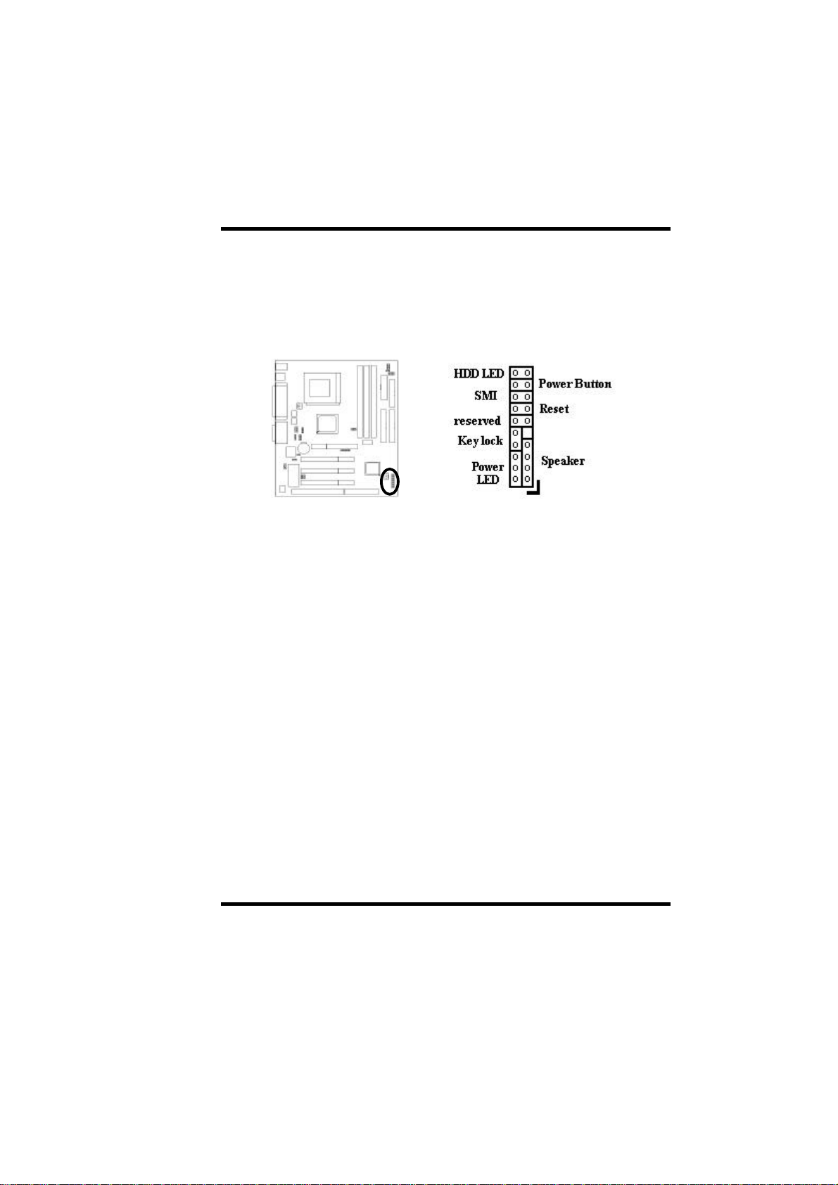
2-2.1 Panel Connector
- Speaker
- Reset
- SMI
- HDD LED
- PWR ON
- Power LED
- Keylock
Chassis Speaker Connector (4 pins)
Reset Switch Connector (2 pins)
SMI Switch Connector (2 pins Reserved)
HDD LED Connector (2 pins)
Power ON Switch Connector (2 pins)
ATX Power LED Connector (3 pin)
Keyboard Lock Switch Connector (2 pins)
AP0 USER'S MANUAL 2-5
Page 19
II.HARDWARE INSTALLATION
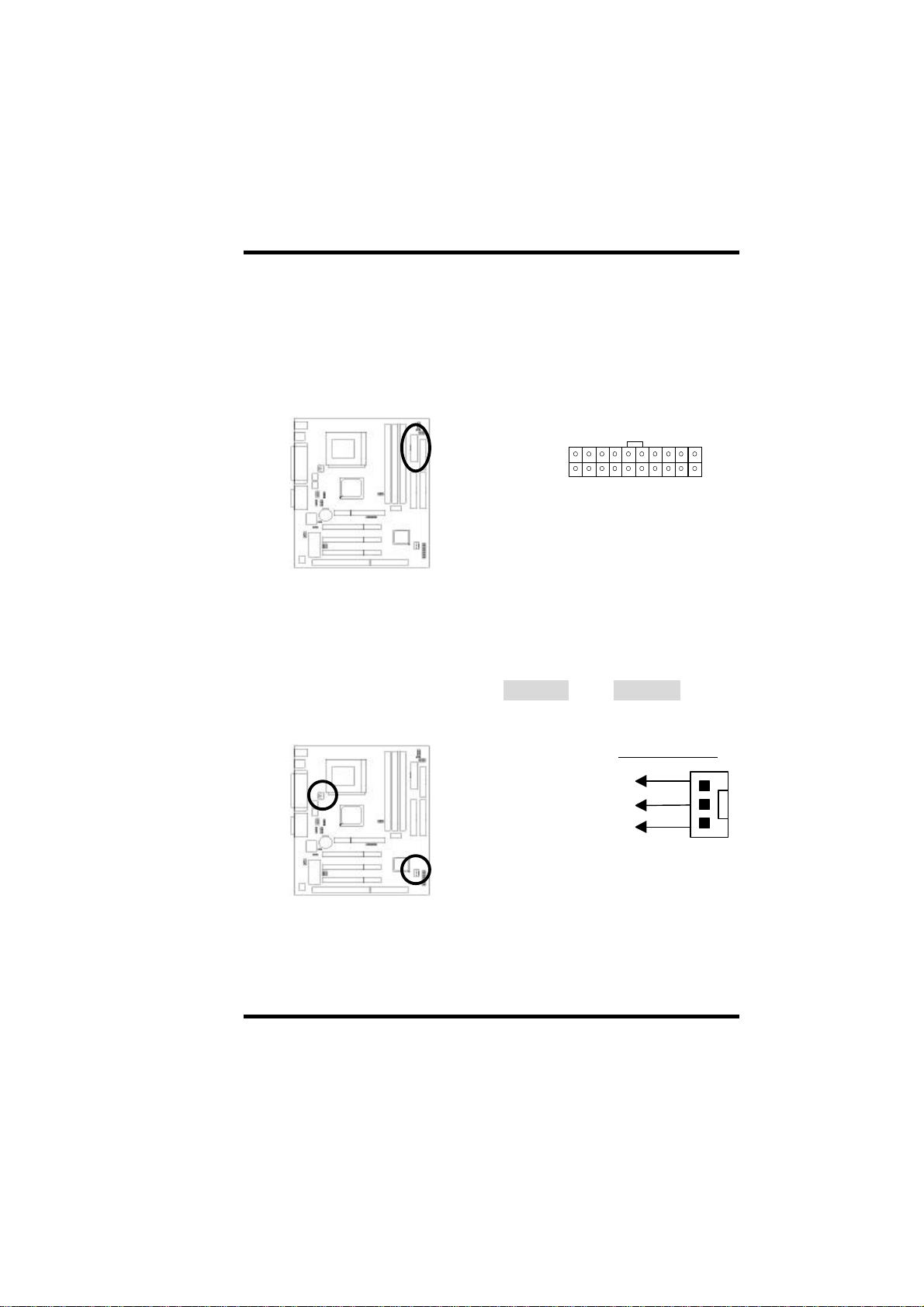
+12v
Fan Connector
2-2.2 Power Connector
Connect the 20-pin ATX power supply cable to this power connector. Make
sure the right plug-in direction and the power supply is off before connecting
or disconnecting the power cable.
ATX Power Connector
2-2.3 Fan Connectors
Connect the CPU and Chassis Fan cables to the fan connectors shown below.
The fan connectors are marked as CPUFAN and CHAFAN on the
mainboard.
CPUFAN
CHAFAN
2-6 AP0 USER’S MANUAL
SENSE
GND
Page 20
II.HARDWARE INSTALLATION
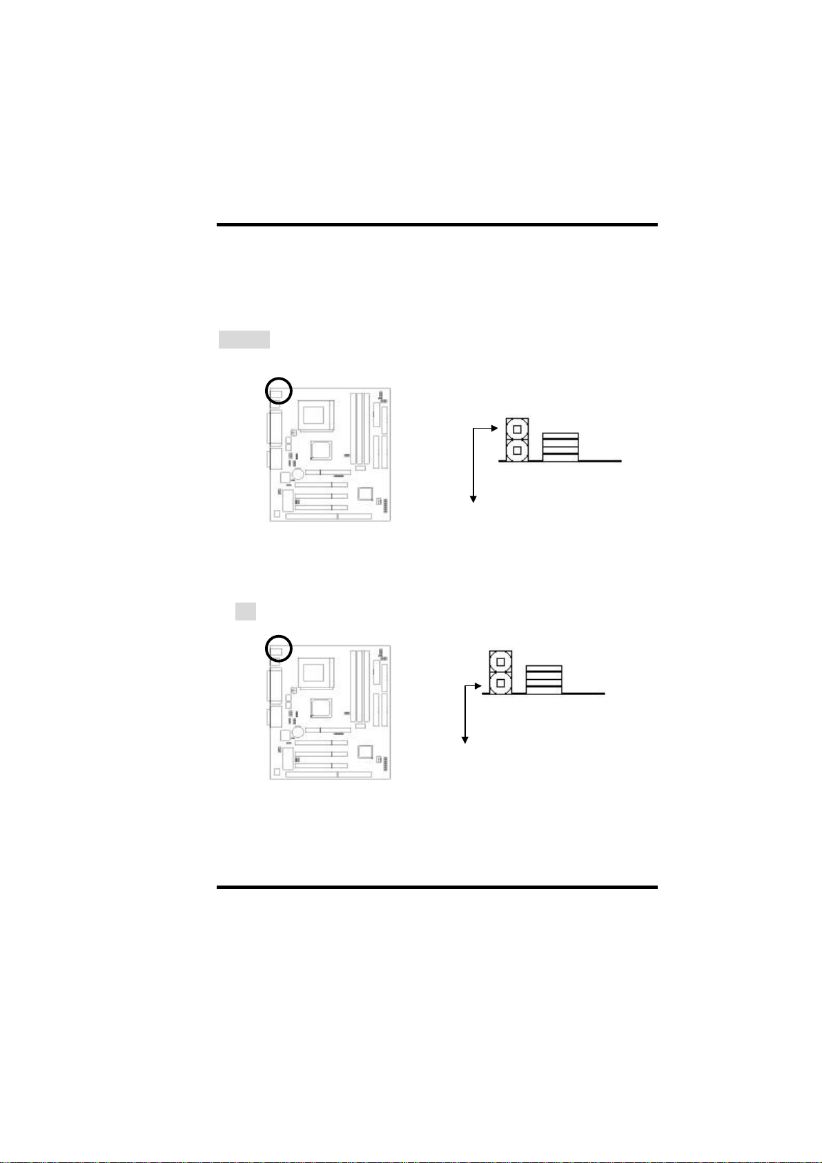
2-2.4 PS/2 Mouse Connector
Connect the PS/2 mouse to the onboard 6-pin Mini-Din connector marked as
MOUSE.
PS/2 Mouse
2-2.5 Keyboard Connector
Connect the PS/2 keyboard to the onboard 6-pin Mini-Din connector marked
as KB.
PS/2 Keyboard
AP0 USER'S MANUAL 2-7
Page 21
II.HARDWARE INSTALLATION
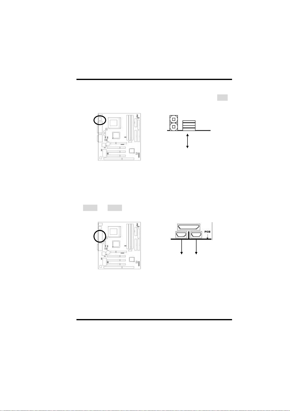
2-2.6 USB Device Connector
Connect your USB device(s) to the onboard USB connector marked as USB.
Top: USB1
Bottom: USB2
2-2.7 Serial Device(COM1/COM2) Connectors
Connect your serial device(s) to the onboard 9-pin serial connectors marked
as COM1 and COM2.
COM1 COM2
2-8 AP0 USER’S MANUAL
Page 22
II.HARDWARE INSTALLATION
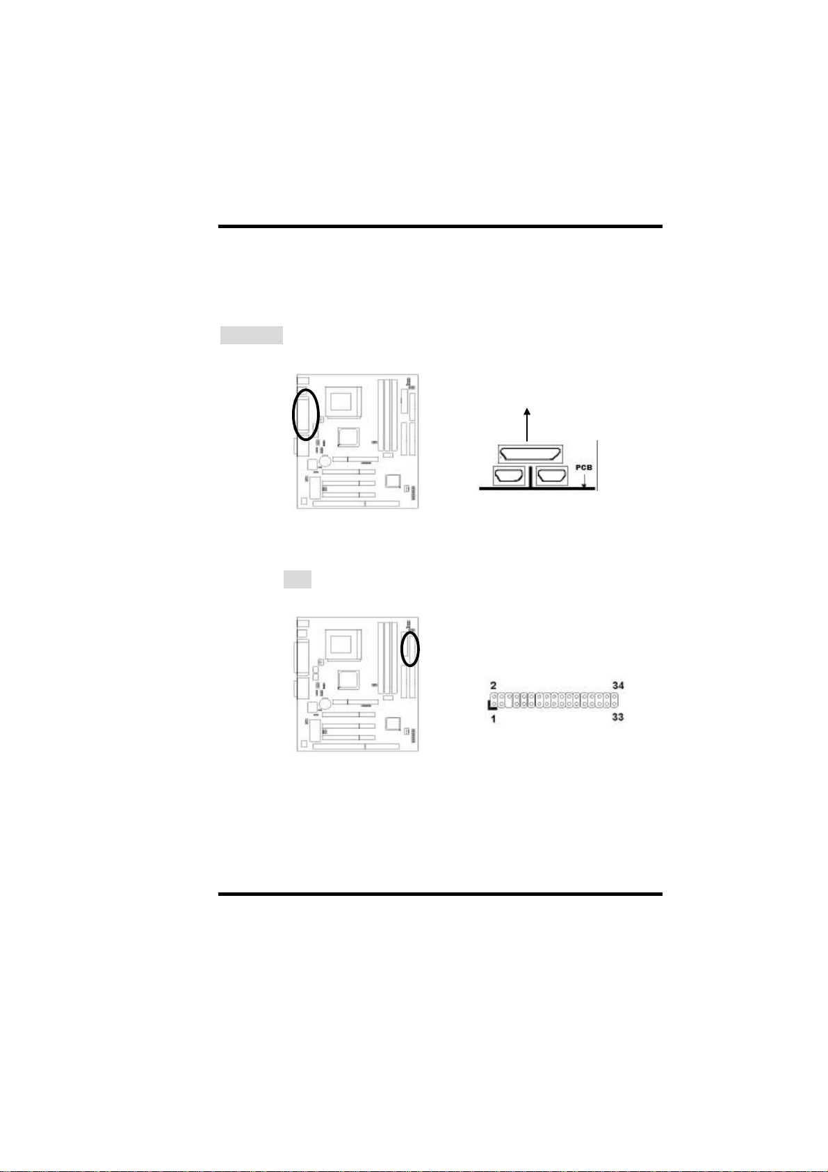
FDD
2-2.8 Printer Connctor
Connect your local printer to the onboard 25-pin printer connector marked as
PRINTER.
PRINTER
2-2.9 Floppy Drive Connector
Connect the floppy drive cable to the onboard 34-pin floppy drive connector
marked as FDD.
AP0 USER'S MANUAL 2-9
Page 23
II.HARDWARE INSTALLATION
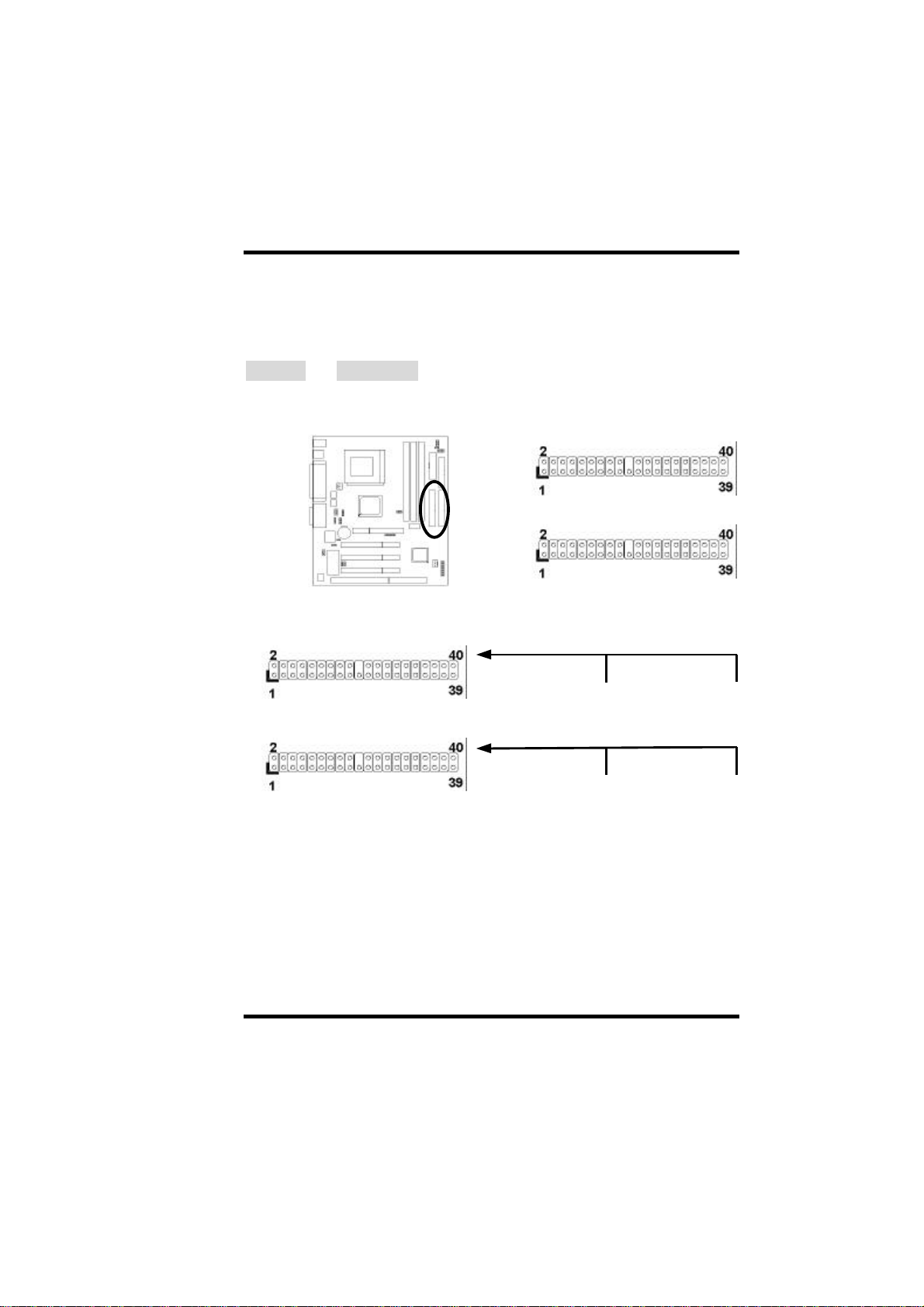
2-2.10 IDE Hard Disk and CD-ROM Connector
Connect your IDE devices to the onboard 40-pin IDE connectors marked as
Primary and Secondary.
Secondary
Primary
Secondary IDE Cable
Secondary
Primary
It is suggested that you connect the IDE devices to your IDE cables as the
figure shown above. Each IDE channel, either Primary or Secondary, supports
two IDE devices which must be set differently to master mode and slave
mode.
(Refer to your hard disk and CD-ROM user’ s manual for detailed settings of
IDE master and slave mode.)
Slave
Primary IDE Cable
Slave
Master
Master
2-10 AP0 USER’S MANUAL
Page 24
II.HARDWARE INSTALLATION
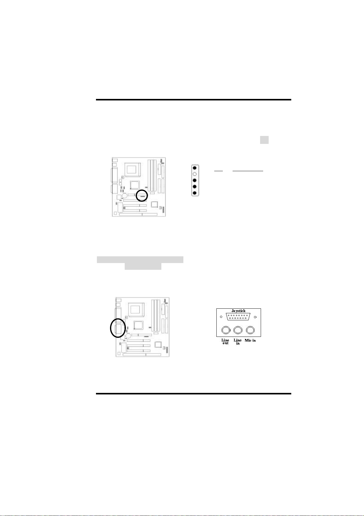
2-2.11 IrDA Connector
Connect your IR device to the onboard IrDA connector marked as IR.
1
2
3
4
5
Pin Description
1 +5V
2 NC
3 IRRX
IR
4 GND
5 IRTX
2-2.12 Game/Audio Connector
Connect the Game/Audio devices to the onboard connector marked as
Joystick/Line in/Line out/MIC in. Connect the audio cable to the onboard
marked as CD1/CD2/AUX.
(J7: This jumper ENABLE/DISABLE the ONBOARD SOUND FUNCTION)
AP0 USER'S MANUAL 2-11
Page 25

II.HARDWARE INSTALLATION
2-12 AP0 USER’S MANUAL
Page 26
II.HARDWARE INSTALLATION
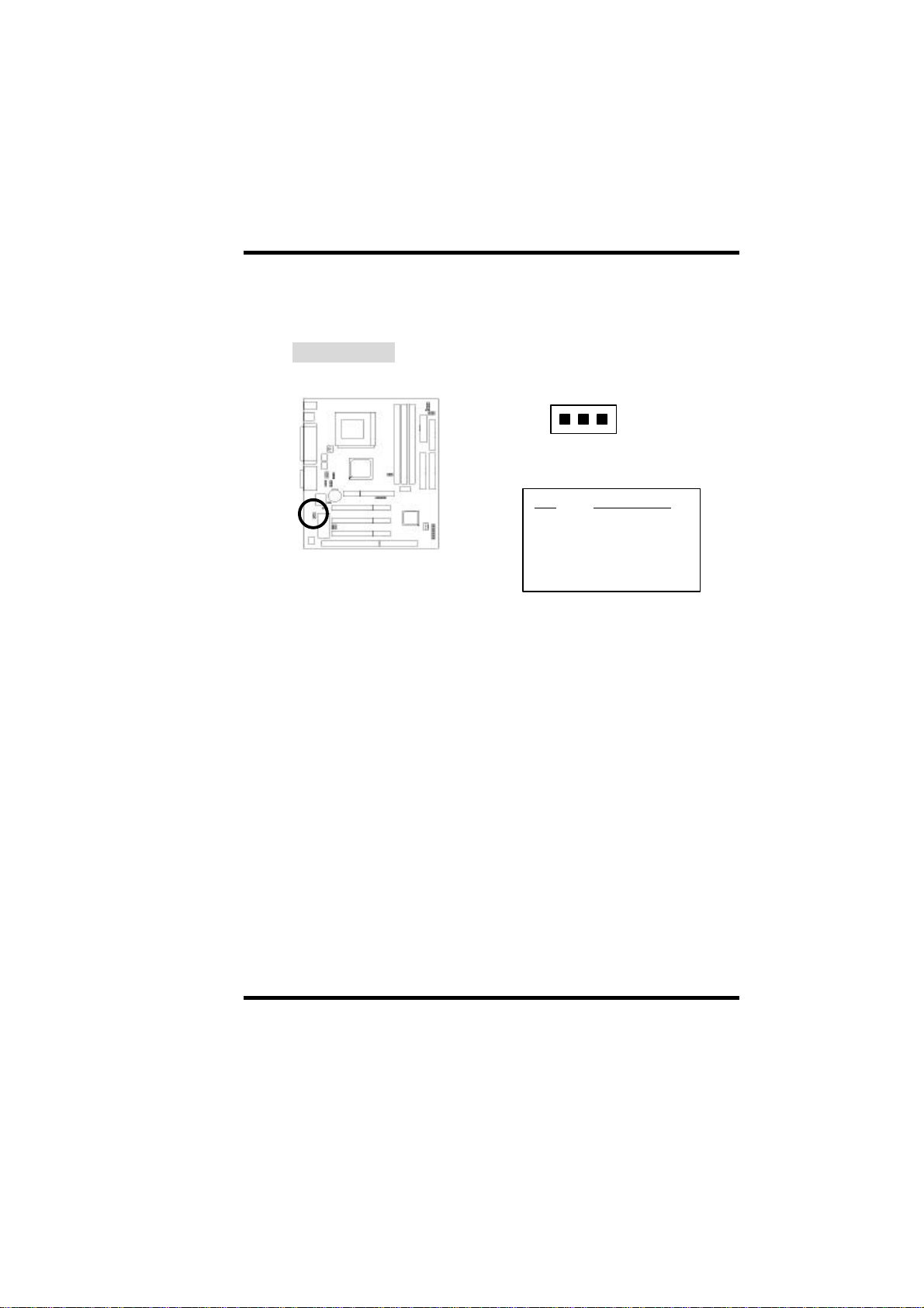
2-2.13 Wake on LAN Connector
This mainboard supports wake up on LAN function. To use this function, you
need a Wake on LAN supported network card and software.
Wake on LAN
1 2 3
Pin Description
1 +5V Standby
2 GND
3 Signal
AP0 USER'S MANUAL 2-13
Page 27
II.HARDWARE INSTALLATION
2-3 System Memory Installation
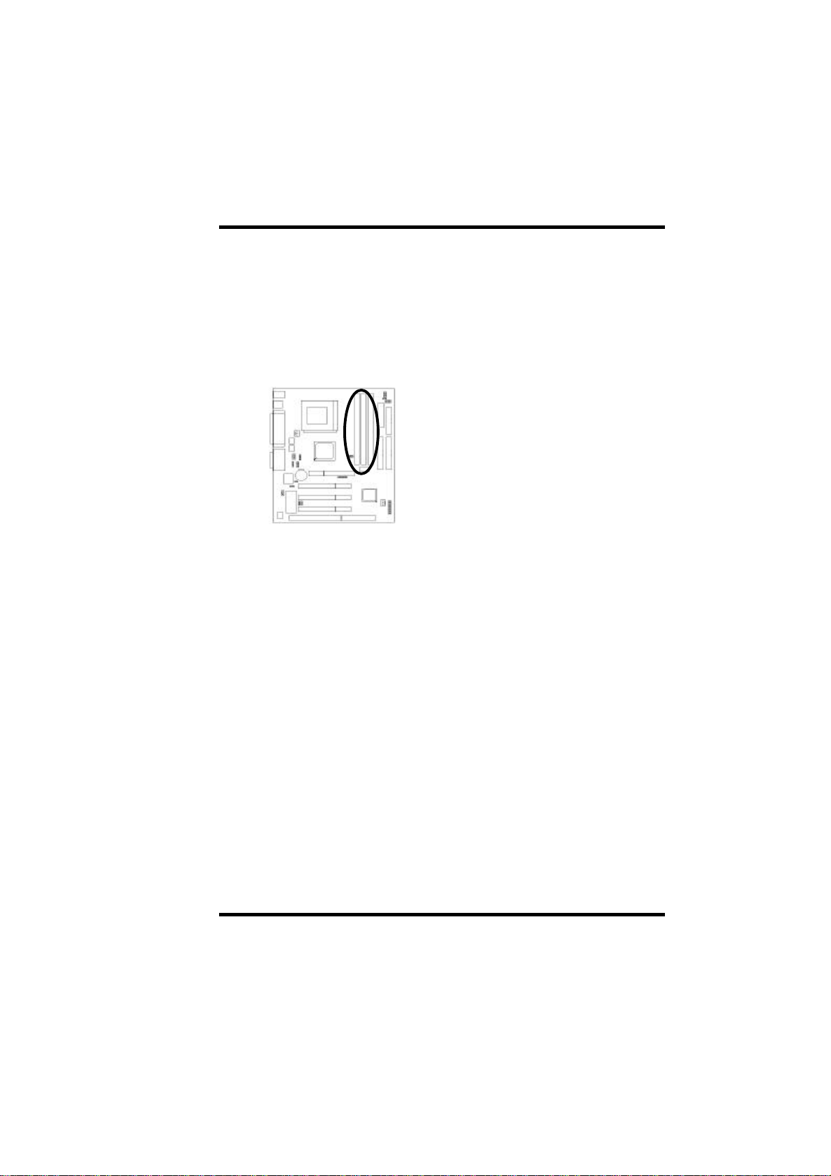
There are 3 168-pin DIMM (Dual Inline Memory Module) sockets on the
mainboard which support Synchronous DRAM and Registered SDRAM, and
allow you install system memory maximum up to 768MB.
DIMM Sockets
2-3.1 Type
This mainboard supports Synchronous DRAM and Registered SDRAM.
However, mixing SDRAM and Registered SDRAM is not allowed. Install one
type only in your system for better compatibility.
2-3.2 Speed
The memory speed normally marked as: -15, -12, -10, -8, -7, PC-100.
The meaning is,
-15 =15ns, and the maximum clock is 66MHz
-12 =12ns, and the maximum clock is 83MHz
-10 =10ns, and the maximum clock is 100MHz
-8 = 8ns, and the maximum clock is 125MHz
-7 = 7ns, and the maximum clock is 142MHz
PC-100 = New Intel specification for high memory speed
With 100MHz or above CPU Bus Clock.
2-14 AP0 USER’S MANUAL
Page 28
II.HARDWARE INSTALLATION
This motherboard supports all the above memory speed. For better system
performance and reliability, we suggest that you use PC-100 SDRAM if
100MHz or above CPU Bus Clock is used in your system.
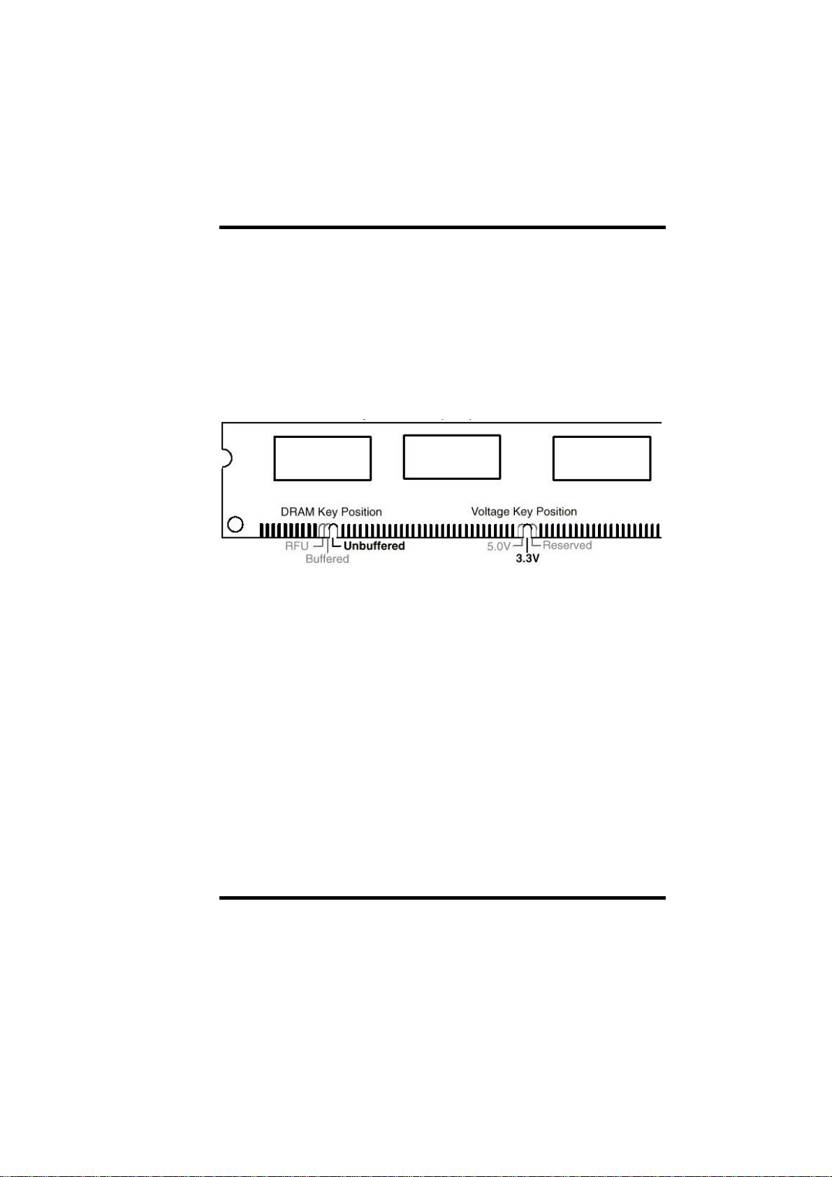
2-3.3 Buffered and Non-buffered
Only the non-buffered DIMM can be used in this mainboard.
The difference between buffered and non-buffered DIMM can be identified by
the notch position shown above.
2-3.4 2-clock and 4-clock signal
Both 2-clock and 4-clock SDRAM DIMM supported by this mainboard.
2-3.5 Parity and Non-parity
This mainboard supports standard 64 bit (Non-parity) and 72 bit (Parity)
DIMM modules.
AP0 USER'S MANUAL 2-15
Page 29

II.HARDWARE INSTALLATION
2-3.6 Memory Auto detection by BIOS
This mainboard BIOS can automatically detect the DIMM memory size and
type, so you do not need to adjust any hardware or software settings. The
maximum memory size supported up to 768MB.
2-3.7 Suggested SDRAM combination
This mainboard supports the following SDRAM combination.
DIMM Location
DIMM 1 SDRAM 8, 16, 32, 64 128, 256MB 256MB
DIMM 2 SDRAM 8, 16, 32, 64 128, 256MB 256MB
DIMM 3 SDRAM 8, 16, 32, 64 128, 256MB 256MB
DIMM Size Memory Size
DIMM1+DIMM2+DIMM3=Total System Memory
768MB
2-16 AP0 USER’S MANUAL
Page 30

SECTION 3.
CMOS SETUP UTILITY
3-1 BIOS Setup Main Menu
This section tells you how to configure the system by changing BIOS setup
options. To enter the BIOS Setup Utility, press DEL key during POST
(Power-On Self Test). The BIOS Setup Main Menu will appear as shown
below.
ROM PCI/ISA BIOS(2A6KL00B)
CMOS SETUP UTILITY
AWARD SOFTWARE, INC.
STANDARD CMOS SETUP W83783S Hardware Monitor
BIOS FEATURES SETUP INTEGRATED PERIPHERALS
CHIPSET FEATURES SETUP PASSWORD SETTING
POWER MANAGEMENT SETUP IDE HDD AUTO DETECTION
PNP/PCI CONFIGURATION HDD LOW LEVEL FORMAT
LOAD BIOS DEFAULTS SAVE & EXIT SETUP
LOAD SETUP DEFAULTS EXIT WITHOUT SAVING
Esc: Quit
F10:Save & Exit Setup (Shift)F2:Change Color
Onboard I/O, IRQ, DMA Assignment
The main menu displays a table of items, which defines basic information
about your system. Below are the keyboard function keys you can use under
the menu.
:Select Item
AP0 USER’S MANUAL 3-1
Page 31
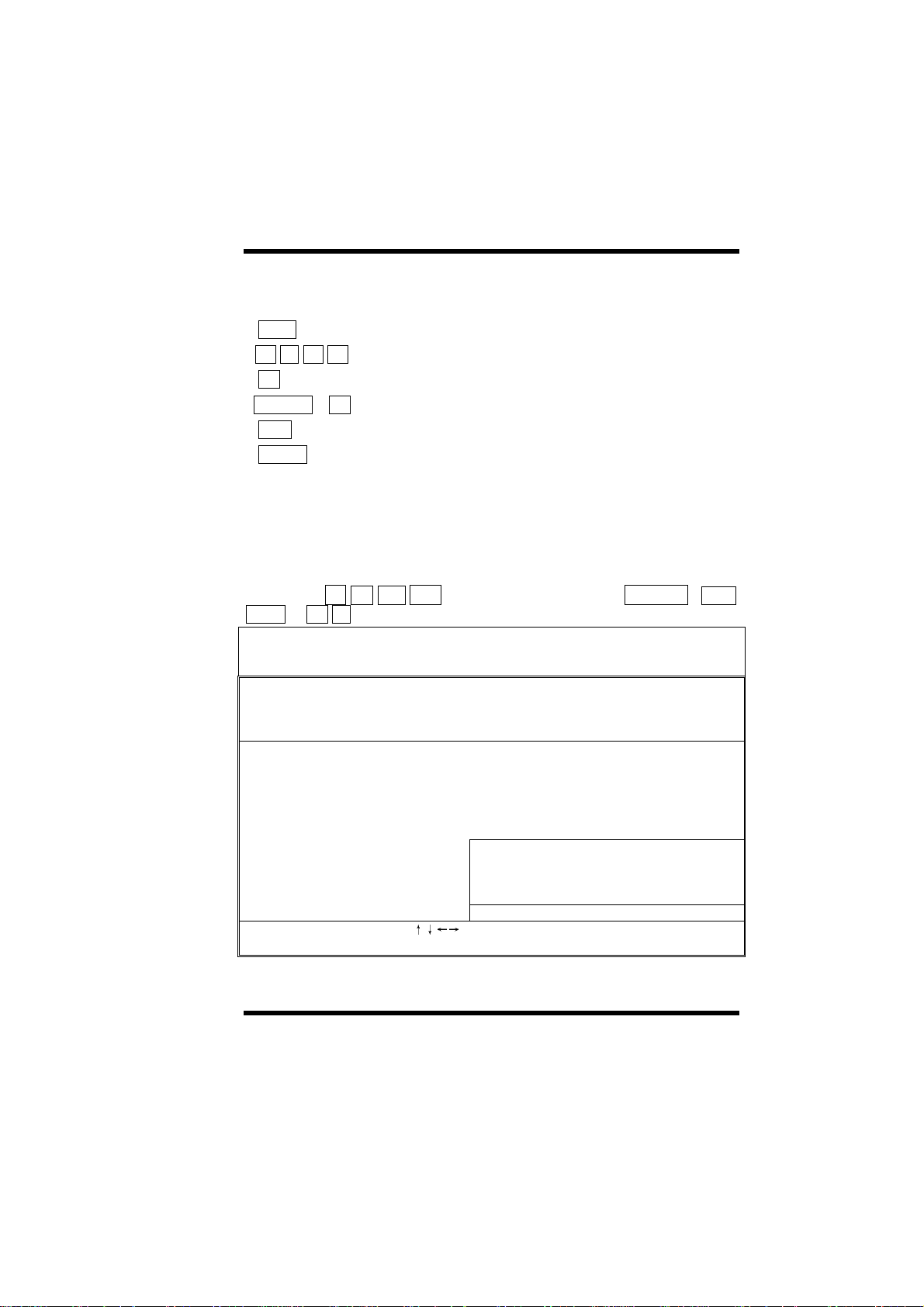
Menu function keys:
E S C
↑ ↓ ←
F 1
S H I F T + F 2
F 1 0
ENTER
To close the BIOS Setup Utility.
→
To move around the screen. An item is highlighted if it is selected.
To displays information about the highlighted item you selected.
To Change the color scheme.
To save the changes before exit the BIOS Setup Utility.
To select or enter a submenu.
3-2 Standard CMOS Setup
This "Standard CMOS Setup" sets the basic system settings such as the date,
time, and the hard disk type, Video display type and error handling. Use the
arrows keys ↑
Down or + - to set the value for each item.
Date (mm:dd:yy): Thu, Apr 3 1998
Time (hh:mm:ss): 14: 8: 0
↓ ← →
ROM PCI/ISA BIOS(2A6KL00B)
AWARD SOFTWARE, INC.
to highlight an item and use Page Up / Page
CMOS SETUP UTILITY
HARD DISKS
Primary Master
Primary Slave
Secondary
Master
Secondary Slave
Drive A : 1.44M, 3.5in Base Memory: 0K
Drive B : None Extended Memory: 0K
Video : EGA/VGA
Halt On : All Errors Total Memory: 512K
ESC: Quit
F1 : Help (Shift)F2:Change Color
TYPE SIZE CYLS HEAD PRECOMP LANDZ SECTOR MODE
: Auto 0 0 0 0 0 0 Auto
: Auto 0 0 0 0 0 0 Auto
: Auto 0 0 0 0 0 0 Auto
: Auto 0 0 0 0 0 0 Auto
Other Memory: 512K
:Select Item
PU/PD/+/-: Modify
3-2 AP0 USER’S MANUAL
Page 32

Ø Date
To set the date, highlight the date area. Press + / - or Page Up / Page
Down to set the current date. The date format is month: Jan. ~ Dec., date:
1 ~ 31, and year: 1994 ~ 2079.
Ø Time
To set the time, highlight the time area. Press + / - or Page Up / Page
Down to set the current time. The time format is hour: 00 ~ 23, minute: 00 ~
59, and second: 00 ~ 59.
Ø Hard Disks à Primary Master
Ø Hard Disksà Primary Slave
Ø Hard Disks à Secondary Master
Ø Hard Disks à Secondary Slave
TYPE:
- Auto
- User
- None
MODE:
- AUTO
- NORMAL
- LBA
- LARGE
This item lets you set your system IDE hard disk type.
Select Auto to let BIOS automatically detects the installed
hard disk when system boot up. Select User if you prefer
manually enters the hard disk type. The available
parameters are SIZE (HDD Size), CYLS (No. of Cylinder),
HEAD(No. Of Head), PRECOMP (Pre-compensation),
LANDZ (Landing Zone), SECTOR (No. Of Sector) and
MODE (HDD Mode). Select None if there is no hard disk
connected to the system.
Default: Auto
Select NORMAL for IDE HDD smaller than 528MB. Select
LBA for IDE HDD over than 528MB and support LBA
(Logical Block Addressing) mode. Select LARGE for IDE
HDD over than 528MB and do not support LBA mode.
Note: We recommend that you set both IDE HDD TYPE
and MODE to AUTO to let BIOS automatically detect the
hard disk drives for you.
Default: Auto
AP0 USER’S MANUAL 3-3
Page 33

Ø Floppy à Drive A
Ø Floppy à Drive B
Drive A / B:
- None
- 360KB - 5.25"
- 1.2MB - 5.25"
- 720KB -3.5"
- 1.44MB - 3.5"
- 2.88MB -3.5"
Ø Video
Video:
- EGA/VGA
- CGA40
- CGA80
- Mono
Ø Halt On
Halt On:
- All Errors
- No Errors
- All, But Keyboard
- All, But Diskette
- All, But Disk/Key
Select the floppy drive type installed in your system.
The available options for Drive A and Drive B are:
360KB 5.25”, 1.2MB 5.25” , 720KB 3.5”, 1.44MB 3.5”,
2.88MB 3.5” and None.
Default: Drive A => 1.44MB 3.5”
Drive B => None
Select the video display card type installed in your
system. The available types are: EGA/VGA, CGA 40,
CGA 80 and Mono.
Default: EGA/VGA
This item defines the operation of the system POST
(Power On Self-Test). You can use this item to select
which kind of errors will cause the system to halt
during POST.
Default: All Errors
3-4 AP0 USER’S MANUAL
Page 34

3.3 BIOS Features Setup
This "BIOS Features Setup" option allows you to setup and improve your
system features and performance.
ROM PCI/ISA BIOS(2AKL00B)
BIOS FEATURES SETUP
AWARD SOFTWARE, INC.
Virus Warning :Disabled Video BIOS Shadow :Enabled
CPU Internal Cache :Enabled C8000-CBFFF :Disabled
External Cache :Enabled CC000-CFFFF :Disabled
Quick Power On Self Test :Disabled D0000-D3FFF :Disabled
Boot Sequence :A,C,SCSI D4000-D7FFF :Disabled
Swap Floppy Drive :Disabled D8000-DBFFF :Disabled
Boot Up Floppy Seek :Enabled DC000-DFFFF :Disabled
Boot Up NumLock Status :On
Boot Up System Speed :High
Gate A20 Option :Normal
Typematic Rate Setting :Disabled
Typematic Rate (Chars/Sec) :6
Typematic Delay (Msec) :250
Security Option :Setup
PS/2 mouse function control :Enabled
PCI/VGA Palette Snoop :Disabled ESC: Quit
Assign IRQ For VGA :Disabled F1: Help PU/PD/+/-: Modify
OS Select For DRAM > 64MB :Non-OS2 F5: Old Values (Shift) F2:Color
Report No FDD For WIN 95 :No F6: Load BIOS Defaults
F7: Load Setup Defaults
:Select Item
Ø Virus Warning
Virus
Warning:
- Enabled
- Disabled
AP0 USER’S MANUAL 3-5
When this item is enabled, the Award BIOS will monitor
the boot sector and partition table of the hard disk drive for
any attempt at modification. If an attempt is made, the
BIOS will halt the system and the error message will
appear, if necessary, you will be able to run an anti-virus
program to locate and remove the problem before any
damage is done.
Page 35

Ø CPU Internal Cache/External Cache
CPU Internal
Cache/External
Cache:
- Enabled
- Disabled
These two categories speed up memory access.
However, it depends on CPU/chipset design. The
default value is enable.
Ø Quick Power-on Self-test
Quick Power-on
Self-test:
- Enable
- Disabled
This item can be used to start operating system
quickly by skip some normal POST checking items.
Ø Boot Sequence
Boot Sequence:
- A,C,SCSI
- C,A,SCSI
- C,CDROM,A
- CDROM,C,A
- D,A,SCSI
- E,A,SCSI
- F,A,SCSI
- SCSI,A,C
- SCSI,C,A
- C only
- LS/ZIP,C
This item defines where the system will look for an
operating system, and the order of priority. The boot
up search sequence shown as left.
Ø Swap Floppy Drive
Swap Floppy
Drive:
- Enabled
- Disabled
If you have two floppy drives in your system, This
item allows you to swap around the assigned drive
letters so that drive A becomes drive B, and drive B
becomes drive A.
3-6 AP0 USER’S MANUAL
Page 36

Ø Boot Up Floppy Seek
Boot Up Floppy
Seek:
- Enabled
- Disabled
This item controls the system to seek floppy drive
during boot up POST.
Ø Boot Up NumLock Status
Boot Up NumLock
Status:
- On
- Off
This item defines if the keyboard NumLock key is
active when your system is started.
Ø Boot Up System Speed
Boot-up System
Speed:
- High
- Low
This item allows the system boot up with High or Low
speed.
Ø Gate A20 Option
Gate A20 Option:
- Normal
- Fast
This entry allows you to select how the gate A20 is
handled. The gate A20 is a device used to address
memory above 1 Mbytes. Initially, the gate A20 was
handled via a pin on the keyboard. Today, while
keyboards still provide this support, it is more
common, and much faster, for the system chipset to
provide support for gate A20.
Ø Typematic Rate Setting
Typematic Rate
Setting:
- Enabled
- Disabled
AP0 USER’S MANUAL 3-7
To Enable or Disable the speed of keyboard to send
repeat keystrokes.
Page 37

Ø Typematic Rate (Chars/Sec)
Typematic Rate:
- 6
- 8
- 10
- 12
- 15
- 20
- 24
- 30
This item provides typematic rate setting, which
allows you to control the repeated keystroke speed.
Ø Typematic Delay (Msec)
Typematic Delay:
- 250
- 500
- 750
- 1000
This item provides typematic delay setting, which
allows you control the delay time between the first
and the second keystroke.
Ø Security Option
Security Option:
- Setup
- System
The “Setup” option is for password request in
entering BIOS setup.
The “System” option is for password request in
entering setup and system boot up.
Ø PCI/VGA Palette Snoop
PCI/VGA Palette
Snoop:
- Enabled
- Disabled
Set this item to Enabled to reduce display problem
when both PCI VGA and some graphic accelerator
devices such as MPEG/Video capture cards are
installed in your system.
3-8 AP0 USER’S MANUAL
Page 38

Ø OS Select for DRAM > 64MB
OS Select for
DRAM > 64MB:
- OS/2
- Non-OS/2
This item is to patch that can not report correct
memory size for more than 64 MB. Set it to OS/2 if
you have an OS/2 installed and have over 64MB
system memory.
Ø Report No FDD For WIN95
Report No FDD
For Win95:
- Yes
- No
While the FDD in “STANDARD CMOS SETUP” is set
to NONE, set this option to No to release IRQ6 for
passing Win95 logo. This option is irrelevant under
normal operation.
Ø Video BIOS Shadow
Video BIOS
Shadow:
- Enabled
- Disabled
This item defines if you leave default setting, video
BIOS memory will be copied from ROM into DRAM
area to enhance system performance as DRAM access
time is faster than ROM.
Ø C8000-CBFFF Shadow to DC000-DFFFF Shadow
C8000-CBFFF to
DC000-DFFFF
Shadow:
- Enabled
- Disabled
Set Enabled if you know the address that your add on
card ROM used to shadow them. If the item is
Enabled, BIOS will copy the selected area from ROM
to RAM to increase system performance.
AP0 USER’S MANUAL 3-9
Page 39

3-4 Chipset Features Setup
This section allows you to configure the system based on the specific features
of the installed chipset. This chipset manages bus speeds and access to
system memory resources, such as DRAM and the external cache. It also
coordinates communications between the conventional ISA bus and the PCI
bus. It must be stated that these items should never need to be altered. The
default settings have been chosen because they provide the best operating
conditions for your system. The only time you might consider making any
changes would be if you discovered that data was being lost while using your
system.
ROM PCI/ISA BIOS(2A6KL00B)
CHIPSET FEATURES SETUP
AWARD SOFTWARE, INC.
Timing Pack of BANK0 :Slow Auto Detect DIMM/PCI CLK :Disabled
SDRAM CAS Latency of BANK0 :3 Clocks Spread Spectrum Modulated :Disabled
Timing Pack of BANK1 :Slow CPU Host/PCI Clock (CPU/PCI) :Default
SDRAM CAS Latency of BANK1 :3 Clocks
Timing Pack of BANK2 :Slow
SDRAM CAS Latency of BANK2 :3 Clocks
Auto Configuration :Disabled
AT Bus Clock :7.16MHz
ECC/EC Option
Local In-Order-Queue Depth :1
DRAM Data Integrity Mode :Disabled
ISA Line Buffer :Disabled
I/O Recovery Period :1 us
System BIOS Cacheable :Enabled
VGA Frame Buffer :16Mb
Video BIOS Cacheable :Enabled ESC: Quit
Video RAM Cacheable :Enabled F1: Help PU/PD/+/-: Modify
AGP2x Mode support :Disabled F5: Old Values (Shift) F2:Color
AGP Aperture Size(MB) :64MB F6: Load BIOS Defaults
Memory Hole 15M-16M :Disabled F7: Load Setup Defaults
:No
ECC/EC
:Select Item
3-10 AP0 USER’S MANUAL
Page 40

Ø Timing Pack of BANK0/1/2
Timing Pack of
BANK0/1/2/3:
- Slow
- Medium
- Fast
- Fastest
The value in this field depends on performance
parameters of the installed memory chips (DRAM).
Do not change the value from the factory setting
unless you install new memory that has a different
performance rating than the original DRAMs.
Ø SDRAM CAS Latency of BANK0/1/2
SDRAM CAS
Latency of
BANK0/1/2/3:
- 2 clocks
- 3 clocks
When synchronous DRAM is installed, the number of
clock cycles of CAS latency depends on the DRAM
timing. Do not reset this field from the default value
specified by the system designer.
Ø Auto Configuration
Auto Configuration:
- Enabled
- Disabled
This item allows you select pre-determined optimal
values for DRAM, cache, and timing according to
CPU type & system clock.
Note: When this item is enabled, the pre-defined
items will become SHOW-ONLY.
Ø AT Bus Clock
AT Bus Clock:
- 7.16MHz
- CLK2/2
- CLK2/3
- CLK2/4
- CLK2/5
- CLK2/6
AP0 USER’S MANUAL 3-11
You can set the speed of the AT bus in terms of a
fraction of the CPU clock speed (PCLK2), or at the
fixed speed of 7.16 MHz.
Page 41

Ø ECC / EC Option
ECC / EC Option:
- No ECC/EC
- ECC ON
- EC ON
You could select the option of ECC (error-correcting
code) / EC (error checking) for memory.
Ø Local In-Order-Queue Depth
Local In-OrderQueue Depth:
- 1
- 2
- 4
- 8
You could select the depth of the Internal IOQ (InOrder-Queue) buffer.
Ø DRAM Data Integrity Mode
DRAM Data
Integrity Mode:
- Disabled
- ECC
- Parity
Select Parity or ECC (error-correcting code),
according to the type of installed DRAM.
Ø ISA Line Buffer
ISA Line Buffer:
- Enabled
- Disabled
The PCI to ISA Bridge has an 8-byte directional line
buffer for ISA or DMA bus master memory reads
from or writes to the PCI bus. When Enabled, an
ISA or DMA bus master can pre-fetch two double
words to the line buffer for a read cycle.
3-12 AP0 USER’S MANUAL
Page 42

Ø I/O Recovery Period
I/O Recovery
Period:
- 1us
- 2us
- 3us
The peripheral controller insert a minimum of 2 bus
clock (BCLK) delays between back-to-back 8- or 16bit ISA I/O cycles issued from the PCI master.
Ø VGA Frame Buffer
VGA Frame
Buffer:
-Disabled
-1 MB
-2 MB
-4 MB
-8 MB
-16MB
When Enabled, a fixed VGA frame buffer from A000h
to BFFFh and a CPU-to-PCI write buffer are
implemented.
Ø Video BIOS Cacheable
Video BIOS
Cacheable:
- Enabled
- Disabled
Selecting Enabled allows caching of the video BIOS
ROM at C0000h to C7FFFh, resulting in better video
performance. However, if any program writes to this
memory area, a system error may result.
Ø Video RAM Cacheable
Video RAM
Cacheable:
- Enabled
- Disabled
Selecting Enabled allows caching of the video BIOS
ROM at C0000h to C7FFFh, resulting in better video
performance. However, if any program writes to this
memory area, a memory access error may result.
AP0 USER’S MANUAL 3-13
Page 43

Ø AGP Aperture Size (MB)
AGP Aperture Size
(MB):
- 16 MB
- 32 MB
- 64 MB
- 128 MB
- 256 MB
Select the size of the Accelerated Graphics Port
(AGP) aperture. The aperture is a portion of the PCI
memory address range dedicated for graphics
memory address space. Host cycles that hit the
aperture range are forwarded to the AGP without any
translation. See www.agpforum.org for APG
information.
3-14 AP0 USER’S MANUAL
Page 44

3-5 Power Management Setup
This option displays a table of items, which lets you control the power
management of the system. Modern operating system takes care of much of
the routine power management. This mainboard supports ACPI (Advanced
Configuration and Power Interface).
ROM PCI/ISA BIOS(2A6KL00B)
POWER MANAGEMENT SETUP
AWARD SOFTWARE, INC.
ACPI Function : Enabled **Standby Events**
Power Management : User Define Bus Master : Disabled
PM Control by APM : Yes Primary HDD : Enabled
MODEM Use IRQ : NA Secondary HDD : Disabled
Video Off Option : Susp,Stby->Off Video I/O Access : Disabled
Video Off Method : DPMs Support Floppy I/O Access : Disabled
**PM Monitor** Serial Port : Disabled
HDD Power Down : Disabled Keyboard Access : Enabled
Doze Mode : Disabled Parallel Port : Disabled
Standby Mode : Disabled
Suspend Mode : Disabled
Power Button : Green Mode
**ON Now Function**
Ring/WakeUp LAN Controller : Disabled ESC: Quit
RTC Alarm Function : Disabled F1: Help PU/PD/+/-: Modify
F5: Old Values (Shift) F2:Color
F6: Load BIOS Defaults
F7: Load Setup Defaults
:Select Item
Ø ACPI Function
ACPI Function:
- Enabled
- Disabled
AP0 USER’S MANUAL 3-15
This item allows you to enable/disable the Advanced
Configuration and Power Management (ACPI).
Page 45

Ø Power Management
Power
Management:
- Max Saving
- Mix Saving
- User Define
- Disabled
This item allows you to set the default parameters
of power-saving modes. Set to Disable to disable
power management function. Set to User Define to
define your own parameters.
Ø PM Controlled by APM
PM Controlled by
APM:
- Yes
- No
Set to Yes to transfer power management control to
APM (Advanced Power Management) and enhance
power saving function.
Ø MODEM Use IRQ
MODEM Use IRQ:
- 3
- 4
- 5
- 7
- 9
- 10
- 11
- NA
This determines the IRQ in which the MODEM can
use.
Ø Video Off Option
3-16 AP0 USER’S MANUAL
Page 46

Video Off Option:
- Always On
- Suspend Off
- Susp,Stuy Off
- All Modes Off
Ø Video Off Method
When enabled, this feature allows the VGA adapter
to operate in a power saving mode.
Video Off Method:
- Blank Screen
- V/H SYNC+Blank
- DPMS Support
This determines the manner in which the monitor is
blanked.
Ø HDD Power Down
HDD Power Down:
- Disabled
- 1 Min
-....
- 15 Min
When enabled and after the set time of system
inactivity, the hard disk drive will be powered down
while all other devices remain active.
Ø Doze Mode
Doze Mode:
- Disabled
- 1 Min.... 15 Min
- 20 Min
- 30 Min
- 40 Min
- 50 Min
- 1 Hour
When enabled and after the set time of system
inactivity, the CPU clock will run at slower speed
while all other devices still operate at full speed.
Ø Standby Mode
AP0 USER’S MANUAL 3-17
Page 47

Standby Mode:
- Disabled
- 1 Min.... 15 Min
- 20 Min
- 30 Min
- 40 Min
- 50 Min
- 1 Hour
When enabled and after the set time of system
inactivity, the fixed disk drive and the video would be
shut off while all other devices still operate at full
speed.
Ø Suspend Mode
Suspend Mode:
- Disabled
- 1 Min.... 15 Min
- 20 Min
- 30 Min
- 40 Min
- 50 Min
- 1 Hour
When enabled and after the set time of system
inactivity, all devices except the CPU will be shut
off.
Ø Power Button Down
Power Button
Down:
- Power Off
When enabled and after the set time of system
inactivity, the power button will be powered down
while all other devices remain active.
- Green Mode
Ø Wake On LAN Use
Wake On LAN Use:
- Enabled
- Disabled
When Enabled, you can set the LAN awakens the
system.
Ø Ring In Controller
3-18 AP0 USER’S MANUAL
Page 48

Ring In Controller:
- Enabled
- Disabled
When Enabled, you can set the Ring-In controller
awakens the system.
Ø RTC Alarm Function
RTC Alarm
Function:
- Enabled
- Disabled
When Enabled, you can set the date and time at
which the RTC (real-time clock) alarm awakens the
system from Suspend mode.
AP0 USER’S MANUAL 3-19
Page 49

Ø WakeUp Date (of Month)
WakeUp Date (of
Month):
- 0
- 1
- .....
- 31
This item displayed only when you enable the RTC
Wake Up Timer item.
You can use this item to specify the date you want to
wake up the system. For Example, if you set to 18,
the system will wake up on the 18th day of every
month. If set to 0, the system will wake up on the
specified time every day.
Ø WakeUp Time (hh:mm:ss)
WakeUp Time
(hh:mm:ss):
- hh:mm:ss
This item is displayed only when you enable the RTC
Wake Up Timer item. You can use this item to
specify the time you want to wake up the system.
Ø Bus Master
Ø Primary HDD
Ø Secondary HDD
Ø Video I/O Access
Ø Floppy I/O Access
Ø Serial Port
Ø Keyboard Access
Ø Parallel Port
Bus Master,
Primary/Secondary
HDD, Video I/O
Access, Floppy I/O
Access, Serial &
Parallel Port:
- Enabled
- Disabled
These items enable or disable the detection of IDE,
Floppy, Serial and Parallel port activities for power
saving mode.
3-20 AP0 USER’S MANUAL
Page 50

3-6 PNP/PCI Configuration Setup
This option display a table of items that configures how PnP (Plug and Play)
and PCI expansion cards operates in your system.
ROM PCI/ISA BIOS(2A6KL00B)
PNP/PCI CONFIGURATION SETUP
AWARD SOFTWARE, INC.
PNP OS Installed :Yes PCI IRQ Active By : Level
Resources Controlled By :Manual
Reset Configuration Data :Disabled
IRQ3 assigned to : Legacy ISA
IRQ4 assigned to : Legacy ISA
IRQ5 assigned to : PCI/ISA PnP
IRQ7 assigned to : PCI/ISA PnP
IRQ9 assigned to : PCI/ISA PnP
IRQ10 assigned to : PCI/ISA PnP
IRQ11 assigned to : PCI/ISA PnP
IRQ12 assigned to : PCI/ISA PnP
IRQ14 assigned to : PCI/ISA PnP
IRQ15 assigned to : PCI/ISA PnP
DMA-0 assigned to : PCI/ISA PnP
DMA-1 assigned to : PCI/ISA PnP ESC: Quit
DMA-3 assigned to : PCI/ISA PnP F1: Help PU/PD/+/-: Modify
DMA-5 assigned to : PCI/ISA PnP F5: Old Values (Shift) F2:Color
DMA-6 assigned to : PCI/ISA PnP F6: Load BIOS Defaults
DMA-7 assigned to : PCI/ISA PnP F7: Load Setup Defaults
:Select Item
Ø PnP OS Installed
PnP OS Installed:
- Yes
- No
AP0 USER’S MANUAL 3-21
Normally, BIOS will allocate the PnP resources during
POST (Power-On Self Test). Set this item to Yes if
you have a PnP operating system such as Windows
95, BIOS will bypass PnP device initial except of boot
device (VGA/IDE or SCSI) and PnP operating system
will do these PnP devices resource allocation. If this
item is set to No, BIOS will handle all PnP devices.
Page 51

Ø Resources Controlled By
Resources
Controlled by:
- Auto
- Manual
Basically, BIOS will allocate the IRQ/DMA resources
automatically for these PNP/PCI and onboard
devices. The exception might be encountered when
legacy ISA devices are installed, which occupies
resources that BIOS can not know. Therefore, this
option is for BIOS to know in advance that IRQ/DMA
is occupied by legacy ISA devices if Manual is
selected.
Ø Reset Configuration Data
Reset Configuration
Data:
- Enabled
- Disabled
When this item is set to Enabled, BIOS will turn it
Disabled again in the next boot up. This item is for
clearing ESCD data. The only reason to clear is the
data loosing the confidence. The engineering test is a
good reason to change the default setting.
Ø IRQ3~5, IRQ7, IRQ9, IRQ10, IRQ11, IRQ12, IRQ14, IRQ15
IRQ 3-5, 7, 9-12,
14-15:
Legacy ISA
PCI/ISA PnP
Set the selected IRQ to Legacy ISA if your ISA card
is not PnP compatible card and requires a special
IRQ to make it function. These options provide IRQ
resources allocation for Legacy ISA or PCI/ISA PnP
card.
Ø DMA 0, DMA 1, DMA 3, DMA 5, DMA 6, DMA 7
DMA 0,1,3,5-7:
- Legacy ISA
- PCI/ISA PnP
Set the selected DMA channel to Legacy ISA if your
ISA card is not PnP compatible card and requires a
special DMA channel to make it function.
3-22 AP0 USER’S MANUAL
Page 52

Ø PCI IRQ Activated by
PCI IRQ Activated
by:
- Level
- Edge
This sets the method by which the PCI bus
recognizes that an IRQ service is being requested by
a device. Under all circumstances, you should retain
the default configuration unless advised otherwise by
your system’ s manufacturer.
AP0 USER’S MANUAL 3-23
Page 53
3.7 Load BIOS Defaults
ROM PCI/ISA BIOS(2A6KL00B)
CMOS SETUP UTILITY
AWARD SOFTWARE, INC.
STANDARD CMOS SETUP W83783S Hardware Monitor
BIOS FEATURES SETUP INTEGRATED PERIPHERALS
CHIPSET FEATURES SETUP PASSWORD SETTING
POWER MANAGEMENT SETUP IDE HDD AUTO DETECTION
PNP/PCI CONFIGURATION HDD LOW LEVEL FORMAT
LOAD BIOS DEFAULTS SAVE & EXIT SETUP
LOAD SETUP DEFAULTS EXIT WITHOUT SAVING
Esc: Quit
F10:Save & Exit Setup (Shift)F2:Change Color
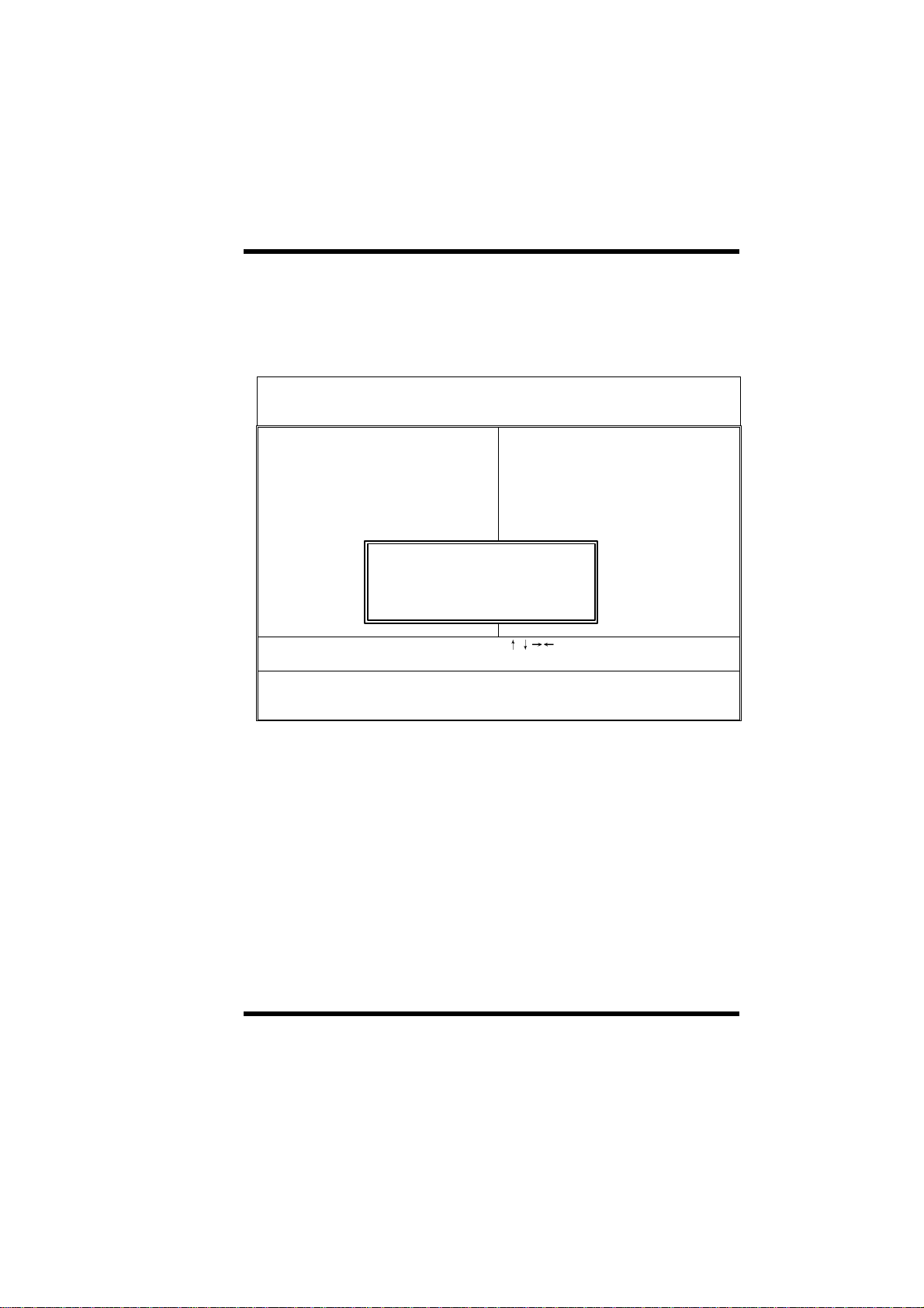
This option allows you load BIOS optimized settings for optimum system
performance. We recommend you to use the optimal settings if your system
has large memory size and fully loading with add-on cards.
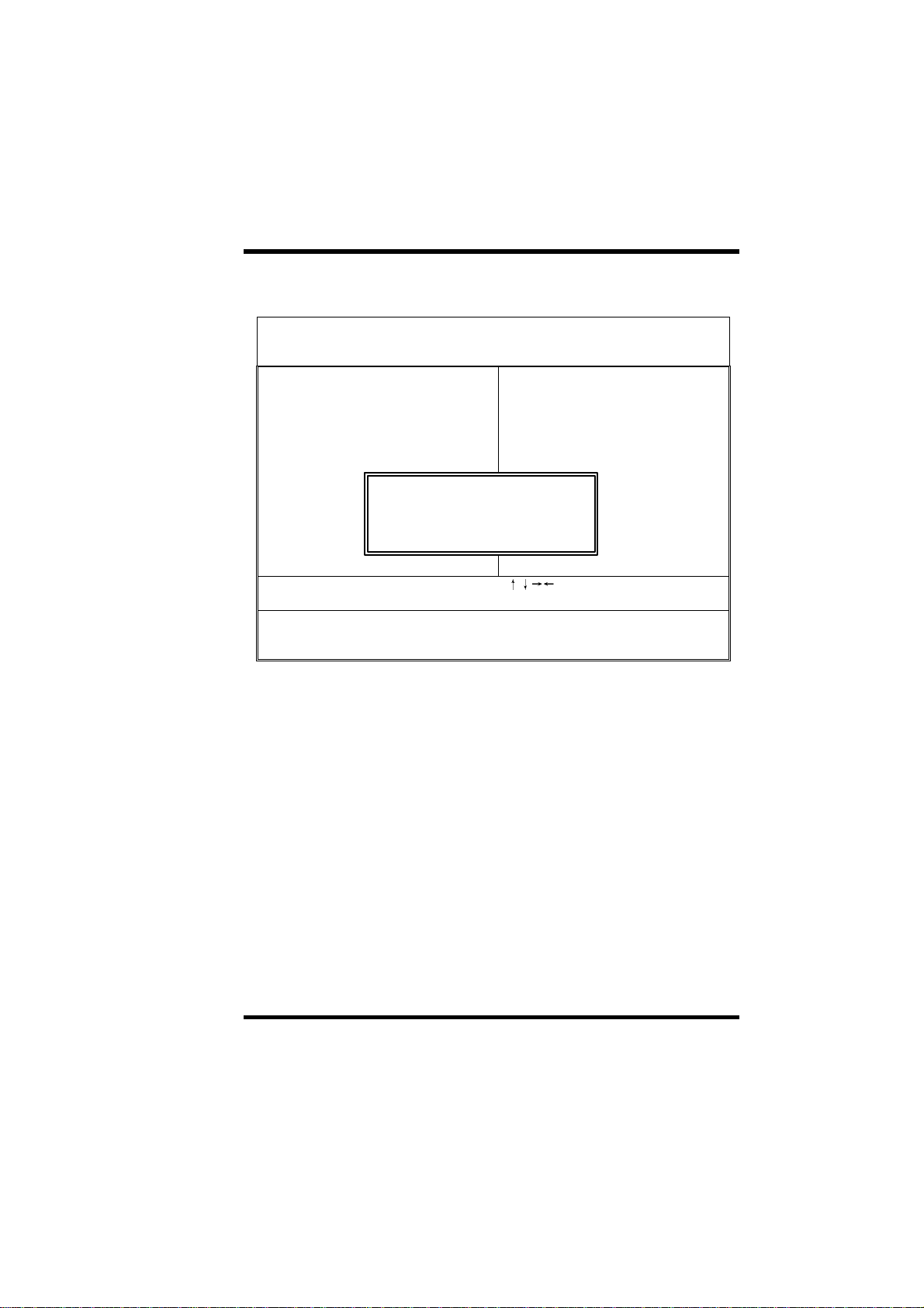
To load Setup Default, press Y key to confirm the operation when you see the
above display.
Load BIOS Defaults (Y/N)? N
:Select Item
Load BIOS Defaults except Standard CMOS SETUP
3-24 AP0 USER’S MANUAL
Page 54
3-8 Load Setup Defaults
ROM PCI/ISA BIOS(2A6KL00B)
CMOS SETUP UTILITY
AWARD SOFTWARE, INC.
STANDARD CMOS SETUP W83783S Hardware Monitor
BIOS FEATURES SETUP INTEGRATED PERIPHERALS
CHIPSET FEATURES SETUP PASSWORD SETTING
POWER MANAGEMENT SETUP IDE HDD AUTO DETECTION
PNP/PCI CONFIGURATION HDD LOW LEVEL FORMAT
Load SETUP Defaults (Y/N)? N
LOAD BIOS DEFAULTS SAVE & EXIT SETUP
LOAD SETUP DEFAULTS EXIT WITHOUT SAVING
Esc: Quit
F10:Save & Exit Setup (Shift)F2:Change Color
Load Setup Defaults except Standard CMOS SETUP
:Select Item
This option provides better performance than optimal setup values. Load the
setup values if you have light system loading, that is, few add-on cards and
memories.
If your system has heavy loading (more add-on cards and memories), you
may manually set the parameters in the "Chipset Features Setup" to get
proper setting to get the best system performance. Before changing any
settings in the "Chipset Features Setup", be sure that you understand the
functions of every item.
AP0 USER’S MANUAL 3-25
Page 55

3-9 W83783S Hardware Monitor
This option allows you to configure the W83783S Hardware Monitor features.
ROM PCI/ISA BIOS(2A6KL00B)
W83783S Hardware Monitor
AWARD SOFTWARE, INC.
CPU Warning Temperature : 40C/104F
Current System Temp. : 23C/75F
Current CPU1 Speed : 21C/69F
Current CPUFAN1 Speed : 0 RPM
Current CPUFAN2 Speed : 0 RPM
Vcore :1.96 V +3.3V :3.39V
+ 5V :4.86 V +12V :11.85V
-12V :-11.04 V
Shoudown Temperature :60C/140F
ESC: Quit
F1: Help PU/PD/+/-: Modify
F5: Old Values (Shift) F2:Color
F6: Load BIOS Defaults
F7: Load Setup Defaults
:Select Item
Ø CPU Warning Temperature
CPU Warning
Temperature:
Select the CPU warning temperature. If your CPU
temperature is higher than the selected temperature,
the BIOS will slow down your CPU process till the
temperature is below the CPU warning temperature
then the CPU will work normally.
3-26 AP0 USER’S MANUAL
Page 56

Ø Current CPU/System Temperature
Current
CPU/System
Temperature:
Indicate the temperature of current CPU/System.
Ø Current CPUFAN1/2 Speed
Current
CPUFAN1/2 Speed:
Indicate the speed of current CPUFAN 1 / CPUFAN
2.On
Ø Shutdown Temperature
Shutdown
Temperature:
Select the Shutdown temperature.
AP0 USER’S MANUAL 3-27
Page 57

3-10 Integrated Peripherals
ECPPP1.9
This option allows you to configure the I/O features.
ROM PCI/ISA BIOS(2A6KL00B)
INTEGRATED PERIPHERALS
AWARD SOFTWARE, INC.
On-Chip Primary IDE : Enabled Onboard UART Port 1 : 3F8/IRQ4
Master PIO : Auto Onboard UART Port 2 : 2F8/IRQ3
Slave PIO : Auto UART2 Mode : Normal
Master Ultra DMA : Disabled
Slave Ultra DMA : Disabled Onboard Parallel Port : 378/IRQ7
On-Chip Secondary IDE : Enabled Parallel Port Mode :
Master PIO : Auto ECP Mode Use DMA : 3
Slave PIO : Auto Onboard IrDA Port : Disable
Master Ultra DMA : Disabled
Slave Ultra DMA : Disabled
IDE HDD Block Mode : Disabled
On-Chip USB Controller : Disabled
Init Display First : PCI Slot
Ali SOUND Controller : Disabled
ESC: Quit
POWER ON Function :BUTTON ONLY F1: Help PU/PD/+/-: Modify
F5: Old Values (Shift) F2:Color
KBC clock source : 8 MHz F6: Load BIOS Defaults
Onboard FDC Controller : Enabled F7: Load Setup Defaults
:Select Item
Ø On-Chip Primary IDE
On-Chip Primary
IDE:
- Enabled
- Disabled
The chipset contains a PCI IDE interface with
support for two IDE channels. Select Enabled to
activate the primary IDE interface. Select Disabled
to deactivate this interface
3-28 AP0 USER’S MANUAL
Page 58

Ø On-Chip Secondary IDE
On-Chip Secondary
IDE:
- Enabled
- Disabled
The chipset contains a PCI IDE interface with
support for two IDE channels. Select Enabled to
activate the secondary IDE interface. Select
Disabled to deactivate this interface
Ø On-Chip Primary/Secondary Master/Slave PIO
On-Chip
Primary/Secondary
Master/Slave PIO:
- Auto
- Mode0/1/2/3/4
The four IDE PIO (Programmed input/output) fields
let you set a PIO mode (0-4) for each of the four IDE
devices that the onboard IDE interface supports.
Modes 0 through 4 provide successively increased
performance. In Auto mode, the system
automatically determines the best mode for each
device
Ø On-Chip Primary/Secondary Master/Slave UDMA
On-Chip
Primary/Secondary
Master/Slave
UDMA:
- Auto
- Mode0/1/2
- Disabled
Ultra DMA/33 implementation is possible only if your
IDE hard drive supports it and the operating
environment includes a DMA driver (Windows 95
OSR2 or a third-party IDE bus master driver). If your
hard drive and your system software both support
Ultra DMA/33, select Auto to enable BIOS support
Ø IDE HDD Block Mode
IDE HDD Block
Mode:
- Enabled
- Disabled
AP0 USER’S MANUAL 3-29
Block mode is also called block transfer, multiple
commands, or multiple sector read/write. If your IDE
hard drive supports block mode (most new drives
do), select Enabled for automatic detection of the
optimal number of block read/writes per sector the
drive can support
Page 59

Ø On-Chip USB Controller
On-Chip USB
Controller:
- Enabled
- Disabled
Select Enabled if your system contains a Universal
Serial Bus (USB) controller
Ø USB Keyboard Support
USB Keyboard
Support:
- Disabled
- Enabled
Select Enabled if your system contains a Universal
Serial Bus (USB) controller and you have a USB
keyboard
Ø Init Display First
Init Display First:
- PCI Slot
- AGP
This item allows you to decide to active whether PCI
Slot or AGP first
Ø POWER ON Function
POWER ON
Function:
- Password
- Hot KEY
- BUTTON ONLY
Set the power on function mode for power on
Ø KB Power ON Password
KB Power ON
Password:
- Enabled
- Disabled
Set the password for the keyboard power on.
3-30 AP0 USER’S MANUAL
Page 60

Ø KBC clock source
KBC clock source:
- 8MHz
- 12MHz
- 16MHz
Set the frequency for the keyboard controller input
clock
Ø Onboard FDC Controller
Onboard FDC
Controller:
- Enabled
- Disabled
Select Enabled if your system has a floppy disk
controller (FDC) installed on the system board and
you wish to use it. If you install and-in FDC or the
system has no floppy drive, select Disabled in this
field
Ø Onboard UART Port 1/Port 2
Onboard UART Port
1/Port 2:
-3F8/IRQ4
-2E8/IRQ3
-3E8/IRQ4
-2F8/IRQ3
- Disabled
- Auto
Select an address and corresponding interrupt for
the first and second serial ports.
Ø UART 2 Mode
UART 2 Mode:
- IrDA
- Norma
- ASK IR
AP0 USER’S MANUAL 3-31
Select an operating mode for the second serial
port.
The choice: IrDA, Normal, ASK IR.
Page 61

Ø Half Duplex time-out
Half Duplex time-out:
- Enabled
- Disabled
Half-duplex mode permits transmission in one
direction only at a time
Ø Onboard Parallel Port
Onboard Parallel
Port:
- 378/IRQ7
- 278/IRQ5
- 3BC/IRQ7
- Disabled.
This item allows you to determine access onboard
parallel port controller with which I/O address
Ø Parallel Port Mode
Parallel Port Mode:
- EPP1.9
- ECP
- ECPEPP1.9
- SPP
- ECPEPP1.7
- EPP1.7.
Select an operating mode for the onboard parallel
(printer) port. Select Normal unless your hardware
and software require one of the other modes offered
in this field.
Ø ECP Mode Use DMA
ECP Mode Use
DMA:
- 1
- 3
Select a DMA channel for the parallel port for use
during ECP mode.
Ø
3-32 AP0 USER’S MANUAL
Page 62

Ø Onboard IrDA Port
Onboard IrDA
Port:
- Disabled
- 2E8H
- 2F8H
- 3E8H
- 3F8H
- 3E0H
- 2E0H
Ø IR IRQ Select
IR IRQ Select:
- IRQ3,
- IRQ4,
- IRQ10
- IRQ11
Ø IrDA Mode
IrDA Mode:
- IrDA1.0
- IrDA1.1
Select the Onboard IrDA port.
You could select the IRQ for the IR.
Select the IrDA mode.
AP0 USER’S MANUAL 3-33
Page 63

3-11 Password Setting
Password prevents unauthorized use of your computer. If you set a password,
the system prompts for the correct password before boot or access to Setup,
the steps as follows,
1. Highlight the item Password Setting on the main menu and press ENTER.
2. The password dialog box will appear.
3. If you are installing a new password, carefully type in the password.
Press ENTER after you have typed in the password. If you are deleting a
password that is already installed just press ENTER when the password
dialog box appears.
4. The system will ask you to confirm the new password by asking you to
type it in a second time. Carefully type the password again and press
ENTER, or just press ENTER if you are deleting a password that is
already installed.
5. If you typed the password correctly, the password will be installed.
[Note]
If you forget your password, or you want to cancel your password, you can do
the steps as the following,
(1) Password forgotten:
i> Turn off the system
ii> Short JP12 at Pin 2-3 for a few seconds to clear CMOS.
iii> Set the JP12 back to Pin 1-2.
iv> Power on the system.
(2) Clear Password:
Clear your password by key-in the password you installed before,
Then go to PASSWORD SETTING to press ENTER twice.
3-34 AP0 USER’S MANUAL
Page 64

3-12 IDE HDD Auto Detection
This item automatically detects and installs any hard disk drives installed on
the primary and secondary IDE channel. Most modern drives can be detected.
If you are using a very old drive that can be detected, you can install it
manually using the Standard CMOS Setup option. Setup will check for two
devices on the primary IDE channel and then two devices on the secondary
IDE channel. At each device, the system will flash an N in the dialog box.
Press Enter to skip the device and proceed to the next device. Press Y, then
Enter to tell the system to accept the BIOS auto-detected device type.
3-13 Save & Exit Setup
Highlight this item and press ENTER to save the changes that you have made
in the setup utility and exit the setup program. When the Save and Exit dialog
box appears, press Y to save and exit, or press N to return to the setup main
menu.
3-14 Exit without Saving
Use this option to exit Setup Utility without saving the CMOS value changes.
AP0 USER’S MANUAL 3-35
Page 65

SECTION 4.
Audio/SOFTWARE UTILITY
4-1 DOS Installation
Before beginning the installation, please make sure that your hard disk has
sufficient space (min. 4MB). Insert the Driver CD into the CD-ROM Drive.
1. Change directory to PCI audio DOS drivers’ folder (ex. D:\DOSDRV) at
DOS prompt, and type:
INSTALL [Enter]
2. Type DOS utilities path, which you want to install.
3. Program will expand the file to the path, which you’ve specified.
4. Install program will add initial drivers into AUTOEXEC.BAT file.
4-2 Win95/98 Installation
We recommend that you install Microsoft Windows before you install this
PCI sound driver, and you not install any other sound device drivers in your
current system.
1. Turn on the computer, and enter the Microsoft Windows 95 / 98.
2. You will see a windows prompt like this:
“New Hardware Found
CMI8338 Audio Adapter (PCI Multimedia Audio Device)
Windows has found new hardware and is installing the software for it”,
then the dialog box shown.
3. Select “Driver form disk provided by hardware manufacturer”, click “OK”.
4. When system requests for CMI8338/C3DX PCI Audio drivers disk,
please make sure the drive and path are pointed to the place where the
installation driver is in, and then click “OK”.
5. Now, system is installing device drivers automatically. After a while, the
system will finish the installation includes the following device drivers.
AP0 USER’S MANUAL 4-1
Page 66

IV.BIOS/SOFTWARE UTILITY
CMI8338/C3DX PCI Audio Device
CMI8338/C3DX PCI Audio Joystick Device
CMI8338/C3DX PCI Audio Legacy Device
DOS mode MPU-401 Emulator
6. Click “start” key
7. Select “Run”
8. Key in the drive and path for Windows application installation program,
for example, “D:\W95-98\APP\SETUP.EXE”
9. Click “OK” to start the installation procedure, and follow the on-screen
instructions to finish the installation. When all the application software
have been installed, please shut down Windows 95/98 system, and
reboot your system.
4-3 Windows NT 4.0 Installation
We recommend that you install Windows NT 4.0 before you install this
PCI audio driver, and you not install any other sound device drivers in
your current system.
1. Click “Start” button, move the highlight bars to “Setting” item, and select
the “Control Panel”.
2. Double-click “Multimedia” icon.
3. Select “Devices” page, and press “Add” button.
4. Select “Unlisted or Updated Driver” item in “List of Drivers”.
5. Specify the drive and the path where NT drivers are in (such as
D:\NT40\DRV).
6. Select “C-Media CM8338” item and press “OK” button.
7. Select proper I/O value.
4-2 AP0 USER’S MANUAL
Page 67

IV.BIOS/SOFTWARE UTILITY
8. Press “OK” button.
9. Restart the system when being asked.
10. Now, you have already installed the PCI Audio Adapter under Microsoft
Windows NT 4.0 successfully. if you want to install the Windows
applications, continue the following steps:
11. Click “start” key.
12. Select “Run” item.
13. Key in drive and path for Windows NT application installation program,
for example, “D:\NT40\APP\SETUP.EXE”
14. Click “OK” to start the installation procedure, and follow the on-screen
instructions to finish the installation. When all of application software
have been installed, shut down the Windows NT system, and then reboot
your system.
AP0 USER’S MANUAL 4-3
Page 68
IV.BIOS/SOFTWARE UTILITY
4-4 Windows Appc. (The Audio Rack)
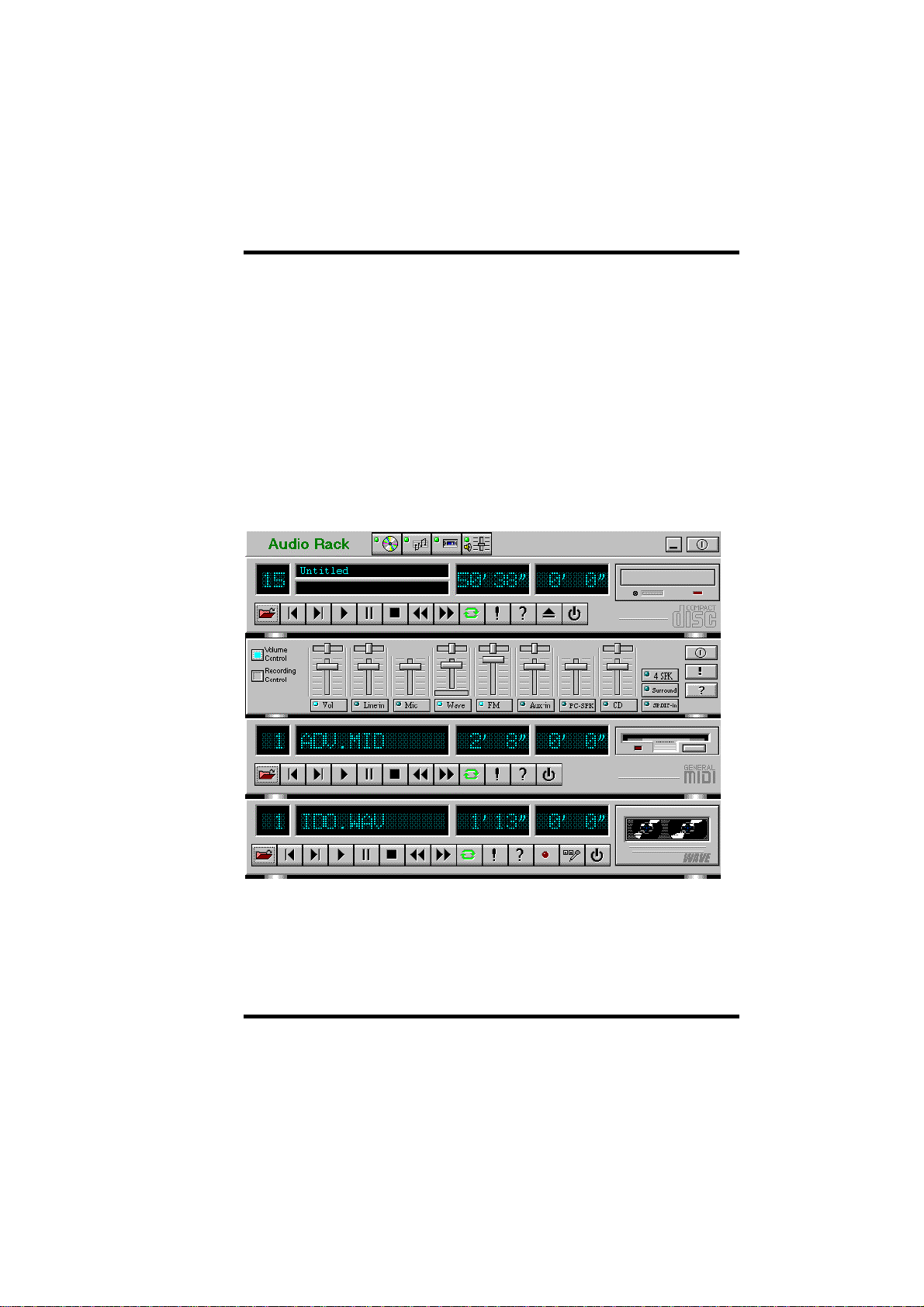
Introduction
By means of a user-friendly interface(as easy as operating your home stereo
system), this PCI audio rack provides you with the control over your PC’s
audio functions, including the advantage of four speakers mode enable/
disable, and perfect digital sound ( SPDIF ) input / output control.
4-4 AP0 USER’S MANUAL
Page 69
IV.BIOS/SOFTWARE UTILITY
This Audio Rack consists of several major components:
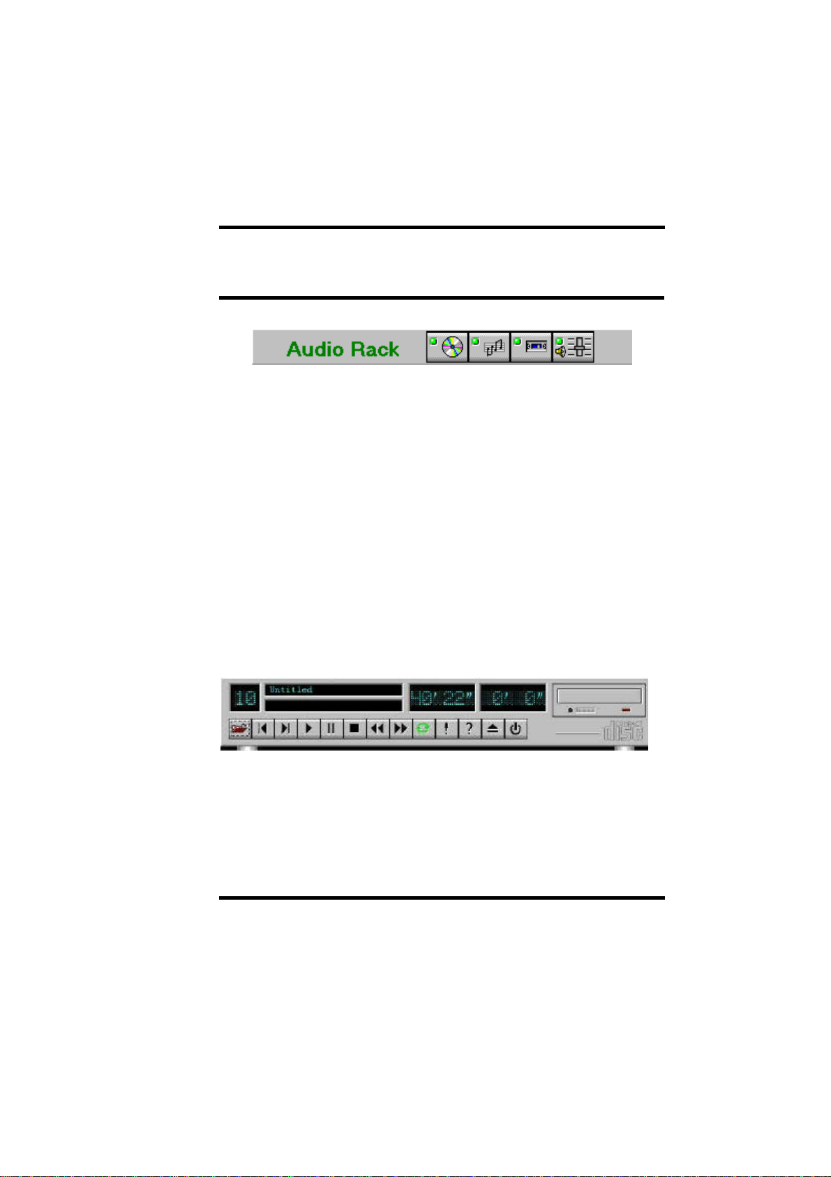
Control Center: Controls the display of the PCI Audio Rack’s components.
MIDI Player: Plays MIDI music files, and allows you to create your personal
song playlists, and play the song files.
Wave Player: Records and plays digital audio (wave) files. Allows you to
create wave file playlists, and playback the wave files.
CD Player: Plays standard audio CDs. Allows you to create your favorite
song playlists.
System Mixer: Controls the volume level of your audio inputs and outputs.
Showing or Hiding Audio Rack Components
To remove or add a component from the display, click on the component's
button on the Control Center’s Button Bar or toggle it off.
MIDI Player, Wave Player, and CD Player
CD Player (above, similar to Wave Player and MIDI Player)
Sel (or Trk) field: If you have multiple selections in your playlist, this shows
the number of the current selection or CD track.
AP0 USER’S MANUAL 4-5
Page 70
IV.BIOS/SOFTWARE UTILITY
Current File or Track: The name of the current MIDI file, wave audio file, or
CD track.
Total Length field: displays the total length of files or tracks in minutes and
seconds.
Current Time field: displays the current time of files or tracks in minutes and
seconds when playback or recording.
Please refer to the help screen for more detail button function
descriptions. (click on help “?” button on the player)
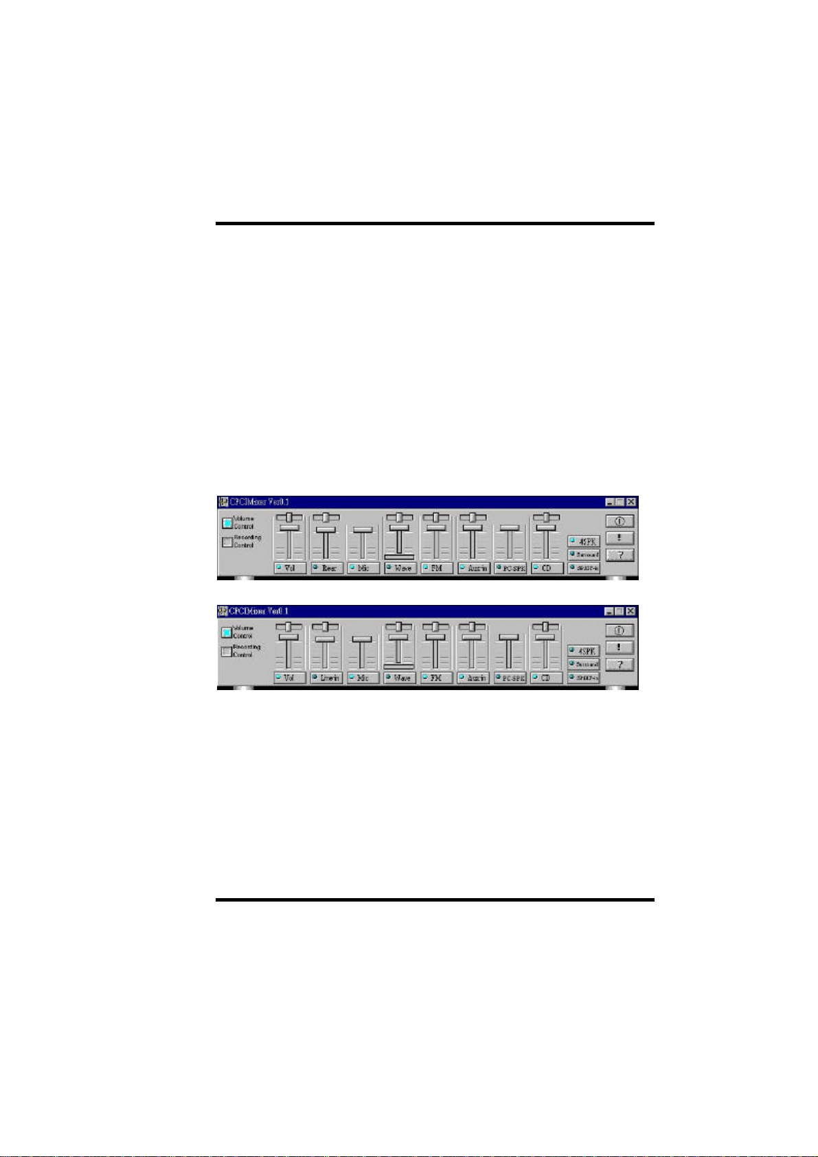
System Mixer
System Mixer allows you to control all the audio output and input levels.
System Mixer displays the volume controls, which your audio drivers make
available. The names for these controls may vary.
Mixer panel while the four speakers mode is enabled.
Mixer panel while the four speakers mode is disabled.
Volume Control: Clicking on this button shows and allows you to use the
output level controls.
Recording Control: Clicking on this button shows and allows you use the
input level controls.
Input and Output Level Sliders and Buttons: For each input or output
signals type, the control slider controls the loudness whereas the horizontal
slider controls the balance between the two speakers. The mute button
temporarily stops input or output without changing slider positions.
4-6 AP0 USER’S MANUAL
Page 71

IV.BIOS/SOFTWARE UTILITY
Control types and names might vary. The common types are listed below:
• Vol: The master control for all outputs. The strength of an output signal is
determined by both the Vol slider and the slider for the individual output.
To affect all outputs, move the Vol slider. To change the output of an
individual output type, move its slider.
• Line-in/Rear: Controls the audio hardware's Line In or Line Out levels.
Line levels might be for an externally attached cassette player, for
instance, while the four speakers’ mode is enabled, this control becomes
the Rear speaker volume control.
• Mic: Controls the microphone-input level.
• Wave: Controls wave (voice) playback or the recording levels.
• FM: Controls the FM music playback or the recording level.
• Aux-in: Controls the Aux-in music play or the recording level.
• PC-SPK: Controls the external PC speaker input level.
• CD: Controls the CD drive output level, for CD drives configured to play
their audio output through the PC’s audio hardware.
• 4SPK: Turn on or turn off the Rear speakers’ effect.
• Surround: Turn on or turn off the 3D surround sound effect.
• SPDIF-in: Turn on or turn off the SPDIF digital signal input.
Mute Buttons: Toggle between muting and enabling the signal. A button with
a lit LED is enabled, and when it is not lit, it means it is mute. Several output
signals can usually be enabled at once.
AP0 USER’S MANUAL 4-7
 Loading...