

EUfire NC951 Design & Installation Manual
Accessible Toilet Alarm
N C 9 5 1 • D E S I G N & I N S T A L L A T I O N G U I D E
Approved Document No.: DNU0951001 Rev 3 • Page 1 of 8
R
e
c
e
p
t
i
o
n
A
r
e
a
s
A
c
c
e
s
s
i
b
l
e
T
o
i
l
e
t
s
I
n
t
e
r
v
i
e
w
R
o
o
m
s
C
h
a
n
g
i
n
g
R
o
o
m
s
Single Zone Emergency Assistance Alarm
+
1
2
3
4
I
ndicators will operate:
Intermittently when help is on the way
R
REESSEETT
Indicators will operate:
C
ontinuously when pull cord is activated
Intermittently when help is on the way
On Calling
Call Accept
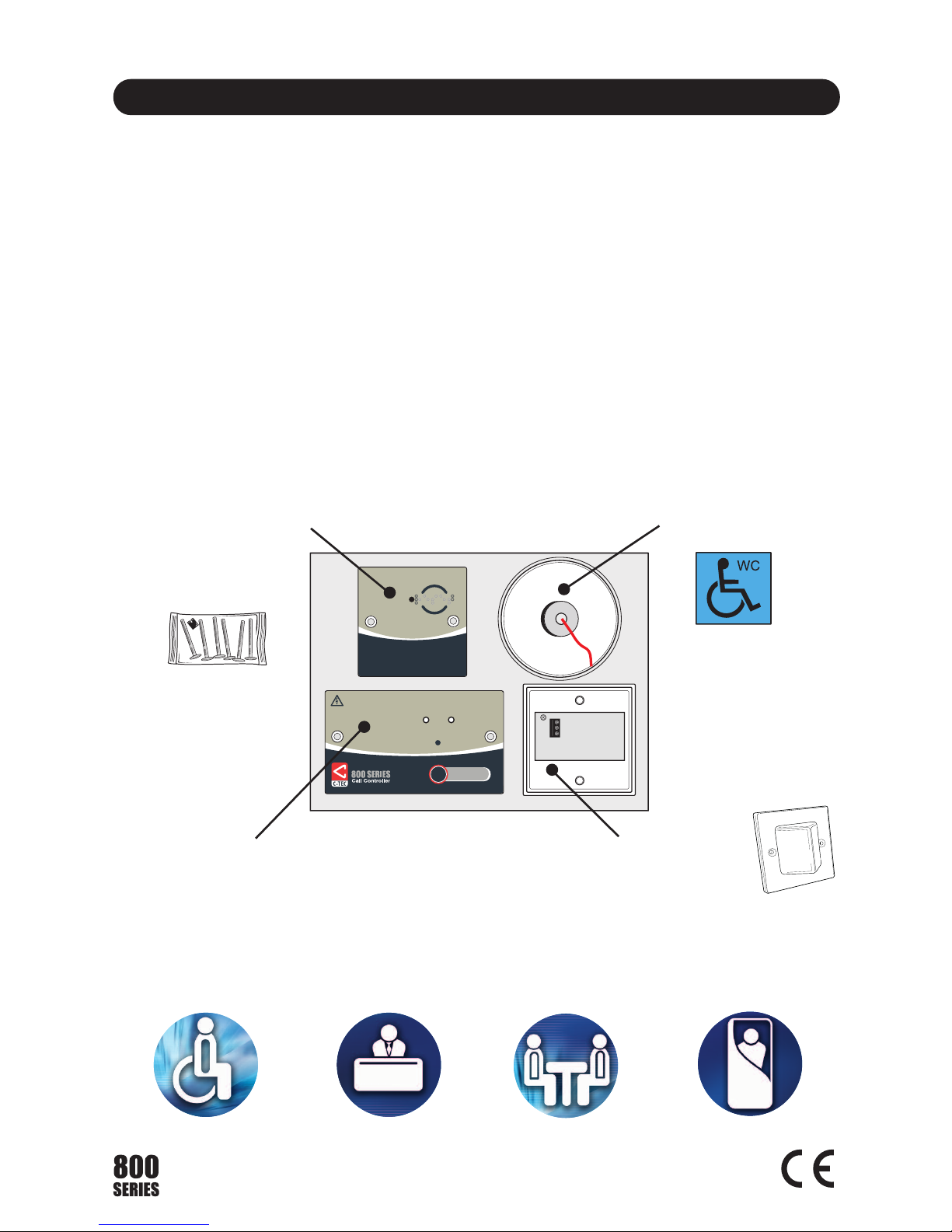
NC951 KIT CONTENTS
NC809DBBT Accessible Toilet Reset Point c/w Sounder
Includes a ‘Reset’ button c/w braille text, red
reassurance LED and sounder.
NC807C Ceiling Pull
Includes a red reassurance LED, red pull cord
and two triangular pull bangles.
NC949 Accessible WC
Sticker
NC943B Single Zone Call Controller c/w Sounder
Includes a link selectable ‘Call Accept’/’Reset’
button, ‘Calling’ and power ‘On’ LEDs, 140mA PSU,
backup battery, volt-free relay output and sounder.
NC806CS Overdoor Light c/w Sounder
Accessory Pack
Containing device
mounting screws
and shorting link.
Documentation
A Design & Installation
Guide (this document).
This equipment must be installed and maintained by a suitably skilled and technically
competent person.
This document provides a brief design and installation overview of the NC951 accessible
toilet alarm system, based on the recommendations of BS 8300 (the code of practice for the
design of buildings and their approaches to meet the needs of disabled people).
Approved Document No.: DNU0951001 Rev 3 • Page 2 of 8
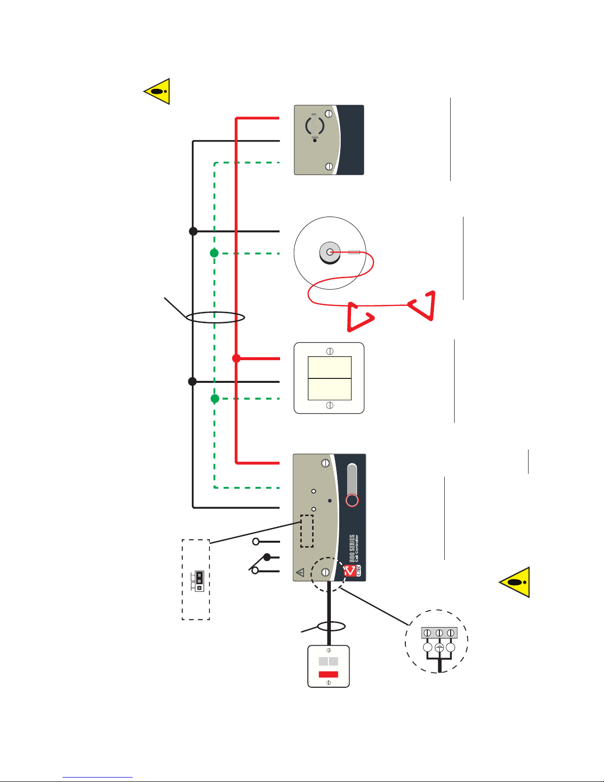
QUICK START INSTALLATION GUIDE
-Ve SIG +Ve
1 -Ve +Ve
Spr Sig -Ve Sig -Ve +Ve
NC C NO
NEGATIVE
SIGNAL
POSITIVE
F
U
S
E
L
N
CONN2
R
REESSEETT
Indicators will operate:
Continuously when pull cord is activated
Intermittently when help is on the way
On Calling
Call Accept
AcceptReset
PLK1
Selectable Link
Mains Connector
230Va.c. from
3A switched
fused spur
(not supplied)
NC943B
Single Zone Call Controller
c/w Sounder
(mounts on a 25mm UK double
gang back box)
TYPICAL LOCATION
Outside the WC in a remote
staffed area.
NC806CS
Overdoor Light
c/w Sounder
(mounts on a
25mm UK single
gang back box)
TYPICAL LOCATION
Outside the WC
above the door.
NC809DBBT
Accessible Toilet Reset
Point c/w sounder
(mounts on a 25mm UK
single gang back box)
TYPICAL LOCATION
Inside the WC so it is
reachable from the toilet
and a wheelchair.
Position 750-1200mm
above floor level and at
least 350mm from corners.
DO NOT connect
+Ve to the ceiling
pull’s signal (Sig)
terminal as this WILL
damage the device.
1mm
2
T&E
Figure 1 below, summarises key information provided in this document. For experienced installers, this should be all you need to get started.
If in doubt, or if using this equipment for the first time, read the full document.
Volt-free
relay contacts
The call controller is a piece of Class 2 equipment.
However, any metal parts used during installation,
i.e. metal back box, MUST
be earthed.
Three cores of four core
stranded burglar alarm cable
NC807C
Ceiling Pull
(surface mounting)
Base fits 16mm
conduit and
BESA centres
TYPICAL LOCATION
Alongside the WC.
Set upper triangle
800-1000mm above
floor level. Set lower
triangle 100mm
above floor level.
Figure 1 : Typical NC951 Accessible Toilet Alarm Wiring
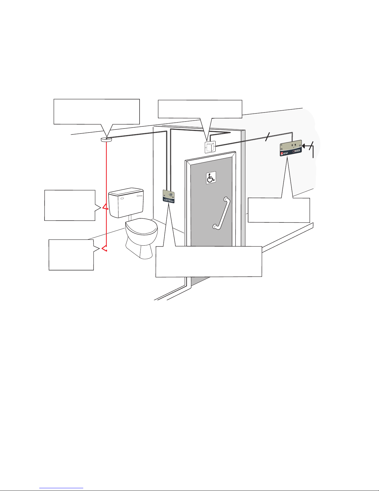
DESIGNING AN ACCESSIBLE TOILET ALARM SYSTEM
Figure 2 below, shows a typical ‘good practice’ layout for an accessible toilet alarm system
based on the recommendations of BS 8300. Always refer to the full version of BS 8300 before
system design/installation.
Figure 2 : Typical BS 8300 Compliant Accessible Toilet Alarm System
W
C
Indicators will operate:
Continuously when pull cord is activated
Approved Document No.: DNU0951001 Rev 3 • Page 3 of 8
Site the ceiling pull so its pull
c
ord can be operated from the
WC and adjacent floor area.
Site the call controller
outside the WC in a
remote staffed area.
Site the reset point so it is reachable
from both the WC and a wheelchair.
Position 750mm - 1200mm above floor
level, at least 350mm from the corners.
Set the lower
triangle exactly
100mm above
floor level.
S
et
t
he upper
t
r
iangle bet
w
een
800m
m
- 1000m
m
abov
e f
loor
lev
el.
4 core
security cable
230Va.c.
3A switched
fused spur.
S
ite the overdoor light outside
the WC above the door.
1mm
2
T&E
 Loading...