

Page 1
Betriebsanleitung Zustimmtaster ZSA/ZSR
Bestimmungsgemäßer Gebrauch
Der EUCHNER-Zustimmtaster ist ein handbetätigter
Befehlsgeber, der Arbeiten im Gefahrenbereich von
automatisierten Fertigungssystemen in der Betriebsart manueller Betrieb ermöglicht. Diese Betriebsart
muss entsprechend EN 60204, Teil 1 mit einem abschließbaren Wahlschalter festgelegt werden.
Der Zustimmtaster ist so mit der Maschinensteuerung
zu verknüpfen, dass die Anforderungen an Stromkreise, die der Sicherheit dienen, gemäß VDI 2854 und/
oder EN ISO 10218-1 erfüllt sind. Unter den dort genannten Bedingungen kann durch das Zustimmsignal
die Schutzwirkung von beweglichen Schutzeinrichtungen aufgehoben werden. Autorisiertes Bedienpersonal kann dann den Gefahrenbereich betreten:
beim Einrichten
beim Beobachten von Arbeitsabläufen
bei der Instandhaltung.
Wichtig:
Der Anwender trägt die Verantwortung für die Einbindung des Geräts in ein sicheres Gesamtsystem. Dazu muss das Gesamtsystem z.B. nach
EN ISO 13849-2 validiert werden.
Wird zur Validierung das vereinfachte Verfahren
nach Abschnitt 6.3 EN ISO 13849-1:2008 benutzt, reduziert sich möglicherweise der Performance Level (PL), wenn mehrere Geräte hintereinander geschaltet werden.
Der Anwender des Zustimmtasters muss bleibende Restrisiken beurteilen und dokumentieren.
Liegt dem Produkt ein Datenblatt bei, gelten die
Angaben des Datenblatts, falls diese von der
Betriebsanleitung abweichen.
Nicht bestimmungsgemäßer Gebrauch
Das Zustimmsignal darf nicht vorgetäuscht werden,
indem das Schaltglied in der Stufe 2 festgesetzt wird.
Sicherheitshinweise
Zustimmtaster erfüllen eine Personenschutz-Funktion. Nicht bestimmungsgemäßer Gebrauch oder
Manipulationen können zu schweren Verletzungen
von Personen führen.
Alle für den speziellen Einsatzfall geltenden Sicherheits- und Unfallverhütungsvorschriften,
wie z.B. Richtlinien der Berufsgenossenschaften, sicherheitstechnischen Anforderungen des
VDI (EN ISO 10218-1, VDI 2854), EN 60204,
EN 12100, EN ISO 13849, EN 61062,
DIN VDE 0106 Teil 100 usw. sind einzuhalten.
Elektromechanische Zustimmtaster/-einrichtungen
sind so mit der Steuerung zu verknüpfen, dass die
Anforderungen an Stromkreise, die der Sicherheit
dienen gemäß EN ISO 10218-1, DIN EN 60204-1,
EN ISO 13849-1, DIN EN ISO 11161 und VDI 2854
erfüllt sind.
Mit dem Zustimmtaster allein dürfen keine Befehle für gefahrbringende Zustände eingeleitet werden.
Die Sicherheitsfunktion von Zustimmtastern
darf nicht umgangen (Kontakte überbrückt),
manipuliert oder auf andere Weise unwirksam
gemacht werden.
Der Zustimmtaster muss gegen Überlistung
durch den Bediener geschützt werden.
Zustimmtaster dürfen nur von autorisierten
Personen bedient werden, die Gefahrenzustände rechtzeitig erkennen und sofort Gegenmaßnahmen einleiten können.
Jede Person, die sich im Gefahrenbereich aufhält, muss einen eigenen Zustimmtaster mit
sich führen.
Montage, elektrischer Anschluss und Inbetriebnahme ausschließlich durch autorisiertes Fachpersonal.
Funktion
Dreistufige Ausführung ZSA2.../ZSR2...
Stufe 1: Aus-Funktion, Stellteil nicht gedrückt
Stufe 2: Zustimmfunktion, Stellteil bis Mittelstel-
lung gedrückt (Druckpunkt)
Stufe 3: Aus-Funktion mit Zwangstrennung, Stell-
teil bis Endanschlag gedrückt
Durch Loslassen des Stellteils oder Durchdrücken
über den Druckpunkt hinaus, wird die Zustimmfunktion
aufgehoben. Bei Rückführung von Stufe 3 in Stufe 1
wird die Zustimmfunktion nicht wirksam. Funktionen
der verschiedenen Ausführungen siehe Bild 1.
Zweistufige Ausführung ZSA1...
Der Taster ZSA1 darf in Sicherheitskreisen
nicht eingesetzt werden.
Stufe 1: Aus-Funktion, Stellteil nicht gedrückt
Stufe 2: Zustimmfunktion, Stellteil bis Endan-
schlag gedrückt
Durch Loslassen des Stellteils wird die Zustimmfunktion aufgehoben. Funktionen der verschiedenen
Ausführungen siehe Bild 1.
Montage
Für den Zustimmtaster ZSA muss eine geeignete
Halterung, z.B. die EUCHNER Halterung Best. Nr.
052 406, verwendet werden.
Elektrischer Anschluss
Die beim Errichten einer Anlage verwendeten
Kabel und Leitungen (ausgenommen Schutzleiter), die bei der Berührung ohne Öffnen oder
Entfernen einer Abdeckung zugänglich oder auf
fremden leitfähigen Teilen verlegt sind, müssen
entweder doppelte oder verstärkte Isolierung
zwischen Ader und Oberfläche aufweisen oder
von einem Metallmantel mit ausreichender
Stromtragfähigkeit für den Fall eines Schlusses
zwischen Ader und Mantel umgeben sein.
Für den Einsatz und die Verwendung gemäß
den
Anforderungen muss eine Spannungsversorgung mit dem Merkmal „for use in
class 2 circuits“ verwendet werden.
Die in den technischen Daten aufgeführte maximale Leitungslänge darf nicht überschritten
werden.
Gefährdungen durch Quetschen oder Zerschneiden der Anschlussleitung müssen durch geeignete Maßnahmen ausgeschlossen werden:
Schutz der Leitung durch entsprechende Verlegung, z.B. in einem Schutzschlauch.
Überwachung von Querschlüssen mit einem Auswertegerät.
Verwendung einer Leitung, deren Adern einzeln
geschirmt sind. Diese Schirme sind mit dem
Schutzleitersystem der Maschine oder Anlage zu
verbinden. Damit werden Leitungskurzschlüsse
erkannt und die Steuerung durch Ansprechen des
Kurzschlussschutzes sofort abgeschaltet.
Inbetriebnahme
Überprüfung des Zustimmtasters (Zustimmfunktion
in Stufe 2 und Zwangstrennung - nicht bei Type
ZSA1 - in Stufe 3) durch Funktionskontrolle.
Wartung und Kontrolle
Wartungsarbeiten sind nicht erforderlich. Um eine
einwandfreie und dauerhafte Funktion zu gewährleisten, sind regelmäßige Kontrollen auf elektrische
und mechanische Funktion erforderlich.
Bei Funktionsstörungen oder Beschädigung
muss der Zustimmtaster ausgetauscht werden.
Instandsetzung nur durch den Hersteller!
Hinweis: Das Baujahr ist in der unteren, rechten
Ecke des Typenschilds ersichtlich.
Haftungsausschluss bei
nicht bestimmungsgemäßem Gebrauch
Nichteinhalten der Sicherheitshinweise
Elektrischem Anschluss nicht durch autorisiertes
Fachpersonal
nicht durchgeführten Funktionskontrollen
EG-Konformitätserklärung
Der nachstehende Hersteller erklärt hiermit, dass
das Produkt in Übereinstimmung ist mit den Bestimmungen der nachfolgend aufgeführten
Richtlinie(n) und dass die jeweiligen Normen zur
Anwendung gelangt sind.
EUCHNER GmbH + Co. KG
Kohlhammerstraße 16
70771 Leinfelden-Echterdingen, Deutschland
Angewendete Richtlinien und Normen:
Taster ZSA1
- Niederspannungsrichtlinie 2006/95/EG
- EN 60947-5-1:2004
Drei-Stellungs-Zustimmtaster
- Maschinenrichtlinie 2006/42/EG
- EMV-Richtlinie 2004/108/EG
- EN 60947-5-8:2006
Leinfelden, November 2010
Dipl.-Ing. Michael Euchner
Geschäftsführer
Duc Binh Nguyen
Dokumentationsbevollmächtigter
Die unterzeichnete EG-Konformitätserklärung ist
dem Produkt beigelegt.
Page 2
Betriebsanleitung Zustimmtaster ZSA/ZSR
Type
ZSA1-1 ZSA1-2 ZSA1-3 ZSA2-1
ZSA2-2 ZSA2-4
Schaltelement
FF
Schaltwegdiagramm
Type ZSA2A4... ZSA2B4...
Schaltelement
F
F
Kontakte offen
Kontakte geschlossen
ZSA2A1...
ZSR2A1...
WH BU GY
BN RD BK
F
ZSA2A2...
ZSR2A2...
WH
BN
Schaltwegdiagramm
F
T
Druckpunkt
1)
1)
642 8
BU
GY
RD
BK
5
1
3
7
E = Schaltelement
F = Füllstück
ZSA2B2...
ZSR2B2...
BU
BN
S3
S2
+
+
+
+
2)
2)
BK
S1
BN BU BK GY
BN BU BK GY
+
+
ZSA2A3...
BN BU BK GY
BN BU BK GY
+
+
+
+
E1
E3+E4
E2
E1
E3+E4
E2
BN
BU
1
4
GY
BK
2
3
Kontakte offen
Kontakte geschlossen
T
Druckpunkt E = Schaltelement
F = Füllstück
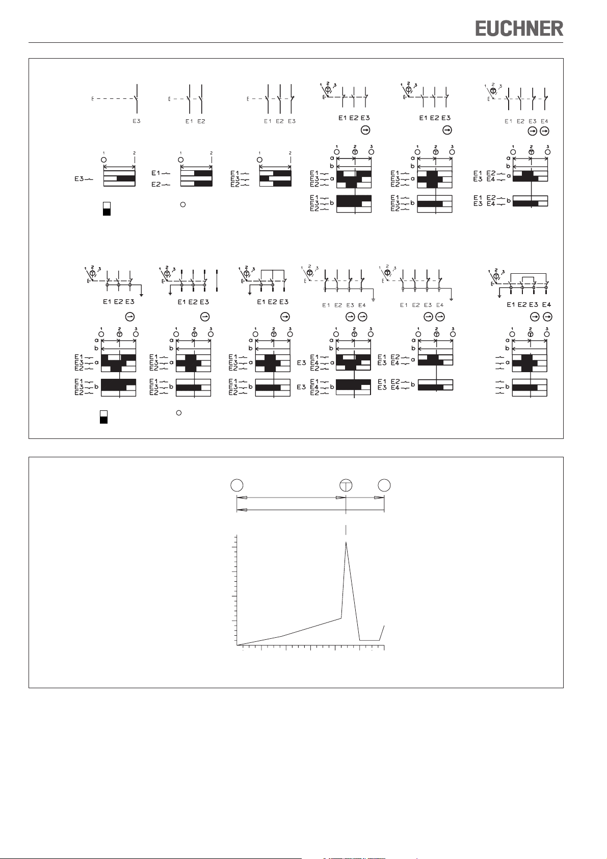
Bild 1: Funktion der Schaltelemente
a
b
1 3
40
30
20
Betätigungskraft ca. [N]
10
0
0
Bild 2: Diagramm Betätigungskraft in Abhängigkeit vom Betätigungsweg
1) mit Steckverbinder nur bei Type ZSA2A2G05C-C1770
2) mit Steckverbinder nur bei Type ZSA2B2G10B
2
2
Betätigungsweg [mm]
4
6
Technische Änderungen vorbehalten, alle Angaben ohne Gewähr. © EUCHNER GmbH + Co. KG 092781-06-11/13 (Originalbetriebsanleitung)
EUCHNER GmbH + Co. KG Kohlhammerstraße 16 D-70771 Leinfelden-Echterdingen Tel. +49/711/75 97-0 Fax +49/711/75 33 16 www.euchner.de info@euchner.de
Page 3
Betriebsanleitung Zustimmtaster ZSA/ZSR
montiert
ZSA1-1/ZSA1-2
ZSA1-3
ZSA2-1/ZSA2-2
ZSA2-4
ZSA2A...
ZSA2B...
Halter für
Zustimmungsschalter ZSA
Gehäusetiefe 70 mm
(Lieferung inkl. Halter
für Wandbefestigung)
Höhe 30 mm
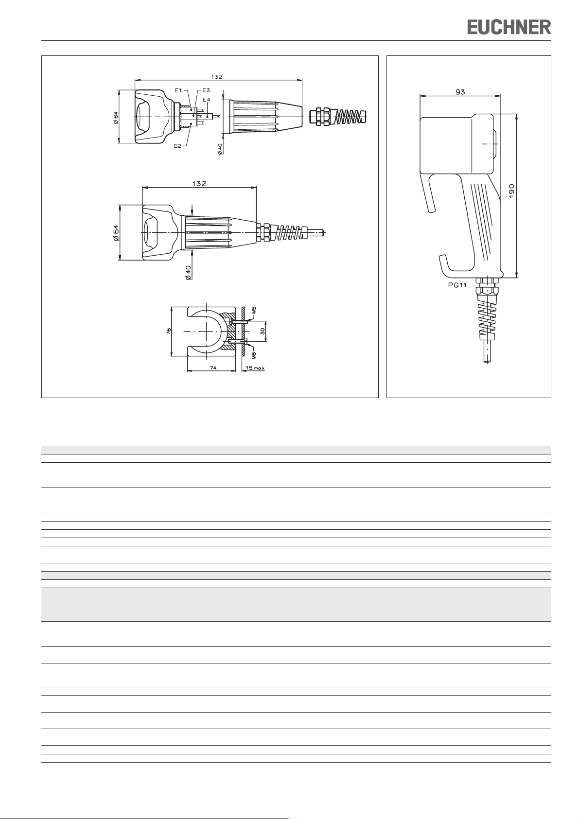
Bild 3: Maßzeichnung Zustimmtaster ZSA und Halter für Zustimmtaster ZSA
Bild 4: Maßzeichnung Zustimmtaster ZSR
Technische Daten
Parameter Wert
Werkstoff Gehäuse Kunststoff
Schutzart nach IEC 60529
ZSA2A, ZSA2B IP67
ZSR, ZSA1-1, ZSA1-2, ZSA1-3, ZSA2-1, ZSA2-2, ZSA2-4 IP65
Lebensdauer min.
Stellung 1-2-1 1x10
Stellung 1-2-3-1 1x10⁵ Zyklen
Umgebungstemperatur -5 ... +50 °C
Schaltelemente siehe Bild 1
Schaltprinzip Schleichschalter
Schaltstrom min. bei 24 V 1 mA
Schaltspannung min.
bei 10 mA
Bedingter Kurzschlussstrom 100 A
Zuverlässigkeitswerte nach EN ISO 13849-1
B
10d
Type
ZSA1-1/ZSA1-2 ZSA2A1... ZSA2A3...
ZSA1-3 ZSA2A2... ZSA2B2... ZSA2A4...
ZSA2-1/ZSA2-2 ZSR2A1... ZSR2B2... ZSA2B4...
ZSA2-4 ZSR2A2... ZSR2A3...
Anschlussart Flachsteckanschluss Anschlussleitung Anschlussleitung Anschlussleitung Steckverbinder Steckverbinder Steckverbinder
2,8 x 0,8 mm 12-polig 7-polig 7-polig
nach IEC 760
Verschmutzungsgrad
(extern, nach EN 60947-1) 3 3 3 3 2 3 3
Anschlussleitung für ∅ 3,5 ... 8,0 mm, 6 x 0,34 mm² 3 x 0,75 mm² 8 x 0,34 mm² 8 x 0,34 mm² 3 x 0,75 mm² 8 x 0,34 mm²
Verschraubung über
Skintop BS9
Leitungslänge max. - 10 m - 10 m 10 m - 10 m
Bemessungsstoß-U
spannungsfestigkeit
= 2,5 kV U
imp
= 2,5 kV U
imp
= 2,5 kV U
imp
Bemessungsisolationsspannung U
Gebrauchskategorie AC-15 4 A 230 V AC-15 2 A 230 V AC-15 4 A 230 V AC-15 2 A 230 V AC-15 2 A 24 V AC-15 4 A 24 V AC-15 2 A 24 V
250 V 250 V 250 V 250 V 32 V 32 V 32 V
i
nach EN 60947-5-1 DC-13 3 A 24 V DC-13 2 A 24 V DC-13 3 A 24 V DC-13 2 A 24 V DC-13 2 A 24 V DC-13 4 A 24 V DC-13 2 A 24 V
Kurzschlusssicherung bei 24 V1)4 A gG 2 A gG 4 A gG 2 A gG 2 A gG 4 A gG 2 A gG
Masse ca. 0,4 kg ca. 1,1 kg ca. 1,1 kg ca. 1,1 kg ca. 1,3 kg ca. 1,3 kg ca. 1,3 kg
1) Bei anderen Betriebsspannungen als DC 24 V muss die Kurzschlusssicherung entsprechend dimensioniert und geprüft werden.
5
Zyklen
12 V
5
5 x 10
= 2,5 kV U
imp
ZSA2A2G...C-C1770 ZSA2B2...B ZSA2B4...B
= 0,8 kV U
imp
= 0,8 kV U
imp
= 0,8 kV
imp
Page 4
Operating Instructions Enabling Switch ZSA/ZSR
Correct use
The EUCHNER enabling switch is a manually
operated command switch, which allows work to
be carried out in the danger area of automated
production systems in manual operating mode.
This mode must be secured with a lockable selector
switch according to EN 60204, part 1.
The enabling switch must be logically gated with
the machine control system in a manner that
ensures compliance with the requirements
applicable to safety circuits according to VDI 2854
and/or EN ISO 10218-1. Under the conditions
specified therein, the enabling signal may cancel
the protective action of moving safety guards.
Authorized operating personnel may then enter the
danger area:
for setting up
for observing work sequences
for maintenance.
Important:
The user is responsible for the integration of the
device in a safe overall system. For this purpose
the overall system must be validated, e.g. in
accordance with EN ISO 13849-2.
If the simplified method according to section 6.3
EN ISO 13849-1:2008 is used for validation, the
Performance Level (PL) may be reduced if several
devices are connected one after the other.
The enabling switch user must assess and
document remaining risks.
If a product data sheet is included with the
product, the information on the data sheet applies
in case of discrepancies with the operating
instructions.
Incorrect use
The enabling signal must not be simulated by fixing
the switching contact in stage 2.
Safety precautions
Enabling switches fulfill a personal protection
function. Incorrect use or tampering can lead to
severe injuries to personnel.
All the safety and accident prevention regulations
for the specific application, e.g. guidelines of the
employers liability insurance associations, safety
requirements of the VDI (EN ISO 10218-1,
VDI 2854), EN 60204, EN 12100, EN ISO 13849,
EN 61062, DIN VDE 0106 part 100, etc., must
be observed.
Electromechanical enabling switches/devices
are to be logically gated with the control system
in a manner that ensures compliance with the
requirements applicable to safety circuits
according to EN ISO 10218-1, DIN EN 60204-1,
EN ISO 13849-1, DIN EN ISO 11161 and
VDI 2854.
No commands for potentially hazardous
conditions are allowed to be initiated with
enabling switches alone.
The safety function of enabling switches must
not be bypassed (bridging of contacts),
manipulated or otherwise rendered ineffective.
The enabling switch must be protected against
attempts by the operator to bypass its
function.
Enabling switches may be used only by
authorized persons who can recognize hazards
in time and who are able to take appropriate
action immediately.
Every person present in the danger area must
carry his/her own enabling switch on his/her
person.
Mounting, electrical connection and setup only
by authorized personnel.
Function
Three-stage ZSA2.../ZSR2...
Stage 1: Off function, pushbutton not pressed
Stage 2: Enabling function, pushbutton pressed to
center position (actuating point)
Stage 3: Positively driven Off function, pushbutton
pushed to end stop
The enabling function is cancelled by releasing the
pushbutton or pressing it beyond the actuating
point. The enabling function does not reactivate
when returning from stage 3 to stage 1. For
information on the functions of the various versions,
see Figure 1.
Two-stage ZSA1...
The ZSA1 switch must not be used in safety
circuits.
Stage 1: Off function, pushbutton not pressed
Stage 2: Enabling function, pushbutton pressed to
end stop
The enabling function is removed by releasing the
pushbutton. For information on the functions of the
various versions, see Figure 1.
Mounting
A suitable holder must be used for the enabling
switch ZSA, e.g. the EUCHNER holder order no.
052 406.
Electrical connection
In the installation of a system, the cables and
wires used (except earth conductors) that can
be touched without opening or removing a
cover, or are laid on conductive parts external
to the device, must be either double insulated
or have reinforced insulation between core and
surface, or be surrounded by a metal sheath
of adequate current-carrying capacity in case
of a short between core and sheath.
For use and operation as per the
requirements, a power supply with the feature
"for use in class 2 circuits" must be used.
The max. cable length listed in the technical
data must not be exceeded.
Hazards due to crushing or cutting of the
connection cable must be prevented by suitable
measures:
Protecting the cable by laying it appropriately,
e.g. in a protective sleeve.
Monitoring short circuits using an evaluation unit.
Using cable with individually screened cores. These screens are to be connected to the machine
or plant earthing system. In this way cable short
circuits can be detected and the control system
shut down immediately by the triggering of the
short circuit protection.
Setup
Check the enabling switch (enabling function at
stage 2 and positively driven – not for type ZSA1 –
at stage 3) by performing a functional check.
Service and inspection
No servicing is required, but to ensure trouble-free
long-term operation, regular inspection of the
electrical and mechanical function is required.
In the event of functional faults or damage,
the enabling switch must be replaced. Repairs
are only to be made by the manufacturer!
Note: The year of manufacture can be seen in the
bottom, right corner of the rating plate.
Exclusion of liability under the following
circumstances
incorrect use
non-compliance with safety regulations
electrical connection not performed by authorized
personnel
function tests not performed
EC declaration of conformity
The manufacturer named below herewith declares
that the product fulfills the provisions of the
directive(s) listed below and that the related
standards have been applied.
EUCHNER GmbH + Co. KG
Kohlhammerstraße 16
70771 Leinfelden-Echterdingen, Germany
Directives and standards applied:
Switch ZSA1
- Low voltage directive 2006/95/EC
- EN 60947-5-1: 2004
Three-position enabling switch
- Machinery directive 2006/42/EC
- EMC directive 2004/108/EC
- EN 60947-5-8:2006
Leinfelden, November 2010
Dipl.-Ing. Michael Euchner
Director
Duc Binh Nguyen
Authorized representative empowered to draw up
documentation
The signed EC declaration of conformity is included
with the product.
Page 5

Operating Instructions Enabling Switch ZSA/ZSR
Type
Switching
element
Travel
diagram
Type ZSA2A4... ZSA2B4...
Switching
element
Travel
diagram
ZSA1-1 ZSA1-2 ZSA1-3 ZSA2-1
FF
F
F
Contacts open
Contacts closed
ZSA2A1...
ZSR2A1...
WH BU GY
BN RD BK
F
ZSA2A2...
ZSR2A2...
WH
BN
F
T
Actuating point
1)
1)
642 8
BU
GY
RD
BK
5
1
3
7
E = Switching element
F = Spacer
ZSA2B2...
ZSR2B2...
BU
BN
S3
S2
2)
2)
BK
S1
BN BU BK GY
BN BU BK GY
+
+
ZSA2A3...
+
+
+
+
ZSA2-2 ZSA2-4
BN BU BK GY
BN BU BK GY
E1
E3+E4
E2
E1
E3+E4
E2
+
+
+
+
BN
BU
1
4
GY
BK
2
3
Contacts open
Contacts closed
T
Actuating point E = Switching element
F = Spacer
Figure 1: Function of the switching elements
a
b
1 3
40
30
20
10
Actuating force approx. [N]
0
0
Figure 2: Diagram of actuating force as a function of actuating travel
1) With plug connector only for type ZSA2A2G05C-C1770
2) With plug connector only for type ZSA2B2G10B
2
2
Actuating travel [mm]
4
6
Subject to technical modifications; no responsibility is accepted for the accuracy of this information. © EUCHNER GmbH + Co. KG 092781-06-11/13 (translation of the original operating instructions)
EUCHNER GmbH + Co. KG Kohlhammerstraße 16 D-70771 Leinfelden-Echterdingen Tel. +49/711/75 97-0 Fax +49/711/75 33 16 www.euchner.de info@euchner.de
Page 6

Operating Instructions Enabling Switch ZSA/ZSR
mounted
ZSA1-1/ZSA1-2
ZSA1-3
ZSA2-1/ZSA2-2
ZSA2-4
ZSA2A...
ZSA2B...
Holder for
enabling
switch ZSA
Housing depth 70 mm
(supplied incl. holder for
wall fastening)
Height 30 mm
Figure 3: Dimension drawing enabling switch ZSA and holder for enabling switch ZSA
Figure 4: Dimension drawing enabling switch ZSR
Technical data
Parameter Value
Housing material Plastic
Degree of protection acc. to IEC 60529
ZSA2A, ZSA2B IP67
ZSR, ZSA1-1, ZSA1-2, ZSA1-3, ZSA2-1, ZSA2-2, ZSA2-4 IP65
Mechanical life min.
Position 1-2-1 1x10
Position 1-2-3-1 1x10⁵ cycles
Ambient temperature -5 ... +50 °C
Switching elements See Figure 1
Switching principle Slow-action contact element
Switching current, min., at 24 V 1 mA
Switching voltage, min.
at 10 mA
Rated short-circuit current 100 A
Reliability values according to EN ISO 13849-1
B
10d
Type
ZSA1-1/ZSA1-2 ZSA2A1... ZSA2A3...
ZSA1-3 ZSA2A2... ZSA2B2... ZSA2A4...
ZSA2-1/ZSA2-2 ZSR2A1... ZSR2B2... ZSA2B4...
ZSA2-4 ZSR2A2... ZSR2A3...
Connection Tab connection Connection cable Connection cable Connection cable Plug connector Plug connector Plug connector
2.8 x 0.8 mm 12-pin 7-pin 7-pin
according to IEC 760
Degree of contamination
(external, acc. to EN 60947-1) 3 3 3 3 2 3 3
Connection cable for ∅ 3.5 ... 8.0 mm, 6 x 0.34 mm² 3 x 0.75 mm² 8 x 0.34 mm² 8 x 0.34 mm² 3 x 0.75 mm² 8 x 0.34 mm²
threaded fitting over
Skintop BS9
Cable length max. - 10 m - 10 m 10 m - 10 m
Rated impulse U
withstand voltage
= 2.5 kV U
imp
= 2.5 kV U
imp
= 2.5 kV U
imp
Rated
insulation voltage U
Utilization category AC-154 A 230 V AC-15 2 A 230 V AC-15 4 A 230 V AC-15 2 A 230 V AC-15 2 A 24 V AC-15 4 A 24 V AC-15 2 A 24 V
250 V 250 V 250 V 250 V 32 V 32 V 32 V
i
according to EN 60947-1-5 DC-13 3 A 24 V DC-13 2 A 24 V DC-13 3 A 24 V DC-13 2 A 24 V DC-13 2 A 24 V DC-13 4 A 24 V DC-13 2 A 24 V
Short circuit protection at 24 V1)4 A gG 2 A gG 4 A gG 2 A gG 2 A gG 4 A gG 2 A gG
Weight approx. 0.4 kg approx. 1.1 kg approx. 1.1 kg approx. 1.1 kg approx. 1.3 kg approx. 1.3 kg approx. 1.3 kg
1) In case of operating voltages other than DC 24 V, the short circuit protection must be dimensioned accordingly and checked.
5
cycles
12 V
5
5 x 10
= 2.5 kV U
imp
ZSA2A2G...C-C1770 ZSA2B2...B ZSA2B4...B
= 0.8 kV U
imp
= 0.8 kV U
imp
= 0.8 kV
imp
Page 7

Mode d’emploi de la commande d’assentiment ZSA/ZSR
Utilisation conforme
La commande d’assentiment EUCHNER est un bouton
de validation manuel permettant de travailler dans la
zone de danger de systèmes de fabrication
automatisés en mode manuel. Ce mode de
fonctionnement doit être protégé par un sélecteur
verrouillable selon la norme EN 60204, partie 1.
La commande d’assentiment doit être reliée à la
commande de la machine conformément aux normes
VDI 2854 et/ou EN ISO 10218-1 afin de satisfaire aux
exigences relatives aux circuits électriques remplissant
des fonctions de sécurité. Dans ces conditions, l’effet
de protection des protecteurs mobiles peut être annulé
par le signal d’assentiment. Le personnel autorisé peut
alors pénétrer dans la zone de danger :
pour l’installation
pour examiner les phases de travail
pour l’entretien.
Important :
L’utilisateur est responsable de l’intégration de
l’appareil dans un système global sécurisé. Ce
dernier doit être validé à cet effet, par ex. selon
EN ISO 13849-2.
Si la validation fait appel à la procédure simplifiée
selon le paragraphe 6.3 EN ISO 13849-1:2008, le
niveau de performance ou Performance Level (PL)
peut diminuer lorsque plusieurs appareils sont
raccordés en série l’un à la suite de l’autre.
L’utilisateur de la commande d’assentiment doit
évaluer et documenter les risques résiduels.
Si le produit est accompagné d’une fiche technique,
les indications de cette dernière prévalent en cas
de différences avec les indications figurant dans le
mode d’emploi.
Utilisation non conforme
Le signal d’assentiment ne doit en aucun cas être
simulé en bloquant le contact en position 2.
Consignes de sécurité
Les commandes d’assentiment remplissent une
fonction de protection des personnes. Une utilisation
ou des manipulations non conformes peuvent
engendrer des blessures graves.
Toutes les normes en vigueur en matière de
sécurité et de prévention des accidents pour
les applications spéciales, comme par ex. les
directives des organismes professionnels, les
exigences de sécurité du VDI (EN ISO 10218-1,
VDI 2854), les normes EN 60204, EN 12100,
EN ISO 13849, EN 61062, DIN VDE 0106 partie
100, etc., doivent être respectées.
Les commandes / dispositifs d’assentiment
électromécaniques doivent être reliés au
système de contrôle conformément aux normes
EN ISO 10218-1, DIN EN 60204-1,
EN ISO 13849-1, DIN EN ISO 11161 et
VDI 2854, afin de remplir les exigences relatives aux circuits électriques et à la sécurité.
La commande d’assentiment ne doit pas être
utilisée seule pour initier des actions susceptibles
de présenter un risque.
La fonction de sécurité des commandes
d’assentiment ne doit pas être contournée
(pontage des contacts), manipulée ou inactivée
de quelque manière que ce soit.
La commande d’assentiment doit être protégée
contre toute utilisation à mauvais escient de la
part de l’opérateur.
Les commandes d’assentiment ne doivent être
utilisées que par le personnel autorisé capable
de déceler assez tôt les situations dangereuses
et d’agir immédiatement en conséquence.
Chaque personne se tenant dans la zone de
danger doit se munir de sa propre commande
d’assentiment.
Montage, raccordement électrique et mise en
service exclusivement par un personnel habilité.
Fonction
Version à trois positions ZSA2.../ZSR2...
Position 1 : arrêt, interrupteur non enfoncé
Position 2 : fonction d’assentiment, interrupteur en-
foncé à moitié (point de déclenchement)
Position 3 : arrêt avec manoeuvre positive
d’ouverture, interrupteur enfoncé jusqu’en
butée
En relâchant l’interrupteur ou en appuyant à fond audelà du point de déclenchement, la fonction
d’assentiment est désactivée. Le passage de la
position 3 à la position 1 désactive la fonction
d’assentiment. Pour les fonctions des différentes
versions, voir figure 1.
Version à deux positions ZSA1...
Le bouton ZSA1 ne doit pas être utilisé dans
des circuits de sécurité.
Position 1 : arrêt, interrupteur non enfoncé
Position 2 : fonction d’assentiment, interrupteur
enfoncé jusqu’en butée
En relâchant l’interrupteur, la fonction d’assentiment
est désactivée. Pour les fonctions des différentes
versions, voir figure 1.
Montage
Pour la commande d’assentiment ZSA, un support
approprié, par ex. le support EUCHNER code article
052 406, doit être utilisé.
Raccordement électrique
Certains câbles utilisés pour le raccordement
d’un protecteur (sauf mise à la terre) peuvent
être touchés sans ouvrir ou retirer un couvercle
ou si ces câbles sont posés sur une partie
conductrice indépendante du dispositif. Dans les
deux cas, ceux-ci doivent bénéficier d’une
isolation double ou renforcée entre le conducteur
et la surface ou être recouverts d’une gaine en
métal suffisamment conductrice pour palier à
l’éventualité d’un court-circuit entre le conducteur
et la gaine.
Pour une utilisation conforme aux exigences
, choisir une alimentation présentant la
caractéristique « for use in class 2 circuits ».
La longueur de câble maximale indiquée dans
les caractéristiques techniques ne doit pas être
dépassée.
Les risques d’écrasement ou de coupure du câble
de raccordement doivent être exclus par des
mesures appropriées :
protéger le câble en le posant correctement,
par ex. dans une gaine protectrice.
contrôler les courts-circuits entre conducteurs
à l’aide d’un analyseur.
utiliser un câble dont les conducteurs sont
blindés séparément. Ces blindages doivent être
reliés à la mise à la terre générale de la machine
ou de l’installation. Les courts-circuits sont ainsi
détectés par la protection contre les courtscircuits et le système de contrôle est
immédiatement coupé.
Mise en service
Vérification de la commande d’assentiment (fonction
d’assentiment en position 2 et manoeuvre positive
d’ouverture -sauf pour ZSA1- en position 3) par un
contrôle fonctionnel.
Entretien et contrôle
Aucun entretien n’est nécessaire. Pour garantir un
fonctionnement irréprochable et durable, il convient
toutefois de vérifier régulièrement les points suivants :
En cas de défaut de fonctionnement ou
d’endommagement, il est nécessaire de
remplacer la commande d’assentiment. Seul le
fabricant est autorisé à réaliser une réparation !
Remarque : l’année de construction figure dans le
coin inférieur droit de la plaque signalétique.
Nous déclinons toute responsabilité
en cas d’utilisation non conforme
en cas de non-respect des consignes de sécurité
si le raccordement électrique est effectué par un
personnel non agréé
si les contrôles fonctionnels ne sont pas effectués.
Déclaration de conformité CE
Le fabricant ci-dessous déclare par la présente que
le produit est conforme aux dispositions de la ou des
directive(s) précisées ci-après ainsi qu’aux normes
qui lui sont applicables.
EUCHNER GmbH + Co. KG
Kohlhammerstraße 16
D-70771 Leinfelden-Echterdingen, Allemagne
Directives et normes utilisées :
Bouton de commande ZSA1
- Directive Basse tension 2006/95/CE
- EN 60947-5-1:2004
Commande d’assentiment à trois positions
- Directive Machines 2006/42/CE
- Directive CEM 2004/108/CE
- EN 60947-5-8:2006
Leinfelden, novembre 2010
Dipl.-Ing. Michael Euchner
Directeur Général
Duc Binh Nguyen
Responsable documentation
La déclaration de conformité CE signée est jointe au
produit.
Page 8

Mode d’emploi de la commande d’assentiment ZSA/ZSR
Modèle
Élément de
commutation
Diagramme
de
commutation
Modèle ZSA2A4... ZSA2B4...
Élément de
commutation
Diagramme
de
commutation
ZSA1-1 ZSA1-2 ZSA1-3 ZSA2-1
FF
F
F
Contacts ouverts
Contacts fermés
ZSA2A1...
ZSR2A1...
WH BU GY
BN RD BK
F
ZSA2A2...
ZSR2A2...
WH
BN
F
T
Point de
déclenchement
1)
1)
642 8
BU
GY
RD
BK
5
1
3
7
E = élément de commutation
F = pièce d’obturation
2)
ZSA2B2...
2)
ZSR2B2...
BU
BK
BN
S3
S1
S2
BN BU BK GY
BN BU BK GY
+
+
ZSA2A3...
+
+
+
+
ZSA2-2 ZSA2-4
BN BU BK GY
BN BU BK GY
E1
E3+E4
E2
E1
E3+E4
E2
+
+
+
+
BN
BU
1
4
GY
BK
2
3
Contacts ouverts
Contacts fermés
T
Point de
déclenchement
E = élément de commutation
F = pièce d’obturation
Figure 1 : Fonction des éléments de commutation
a
b
1 3
40
30
20
10
Force d’actionnement env. [N]
0
0
Figure 2 : Diagramme force d’actionnement en fonction du déplacement
1) avec connecteur uniquement pour ZSA2A2G05C-C1770
2) avec connecteur uniquement pour ZSA2B2G10B
2
2
Déplacement [mm]
4
6
Sous réserve de modifications techniques, indications non contractuelles. © EUCHNER GmbH + Co. KG 092781-06-11/13 (trad. mode d’emploi d’origine)
EUCHNER GmbH + Co. KG Kohlhammerstraße 16 D-70771 Leinfelden-Echterdingen Tél. +49/711/75 97-0 Fax +49/711/75 33 16 www.euchner.de info@euchner.de
Page 9

Mode d’emploi de la commande d’assentiment ZSA/ZSR
en place
ZSA1-1/ZSA1-2
ZSA1-3
ZSA2-1/ZSA2-2
ZSA2-4
ZSA2A...
ZSA2B...
Profondeur du boîtier 70 mm
Support pour
commande
d’assentiment
ZSA
(la livraison inclut le support
de fixation mural)
Hauteur 30 mm
Figure 3 : Dimensions commande d’assentiment ZSA et support pour commande d’assentiment ZSA
Figure 4 : Dimensions commande d’assentiment ZSR
Caractéristiques techniques
Paramètre Valeur
Matériau du boîtier Plastique
Indice de protection selon IEC 60529
ZSA2A, ZSA2B IP67
ZSR, ZSA1-1, ZSA1-2, ZSA1-3, ZSA2-1, ZSA2-2, ZSA2-4 IP65
Durée de vie min.
Position 1-2-1 1x10
Position 1-2-3-1 1x10⁵ cycles
Température ambiante -5 ... +50 °C
Éléments de commutation voir figure 1
Principe de commutation Interrupteur à action dépendante
Pouvoir de coupure min. à 24 V 1 mA
Tension de commutation min.
à 10 mA
Courant conditionnel de court-circuit 100 A
Valeurs de fiabilité selon EN ISO 13849-1
B
10d
Modèle
ZSA1-1/ZSA1-2 ZSA2A1... ZSA2A3...
ZSA1-3 ZSA2A2... ZSA2B2... ZSA2A4...
ZSA2-1/ZSA2-2 ZSR2A1... ZSR2B2... ZSA2B4...
ZSA2-4 ZSR2A2... ZSR2A3...
Type de raccordement Raccord par fiche plate Câble Câble Câble Connecteur Connecteur Connecteur
2,8 x 0,8 mm de raccordement de raccordement de raccordement 12 broches 7 broches 7 broches
selon IEC 760
Degré de pollution
(externe, selon EN 60947-1) 3 3 3 3 2 3 3
Câble de raccordement pour ∅ 3,5 ... 8,0 mm, 6 x 0,34 mm² 3 x 0,75 mm² 8 x 0,34 mm² 8 x 0,34 mm² 3 x 0,75 mm² 8 x 0,34 mm²
Vissage par
Skintop BS9
Longueur de câble max. - 10 m - 10 m 10 m - 10 m
Tension nominale U
d’essai (impulsion)
= 2,5 kV U
imp
= 2,5 kV U
imp
= 2,5 kV U
imp
Tension nominale
d’isolement U
Catégorie d’emploi AC-154 A 230 V AC-15 2 A 230 V AC-15 4 A 230 V AC-15 2 A 230 V AC-15 2 A 24 V AC-15 4 A 24 V AC-15 2 A 24 V
i
selon EN 60947-5-1 DC-13 3 A 24 V DC-13 2 A 24 V DC-13 3 A 24 V DC-13 2 A 24 V DC-13 2 A 24 V DC-13 4 A 24 V DC-13 2 A 24 V
Protection cc à 24 V
250 V 250 V 250 V 250 V 32 V 32 V 32 V
1)
4 A gG 2 A gG 4 A gG 2 A gG 2 A gG 4 A gG 2 A gG
Masse env. 0,4 kg env. 1,1 kg env. 1,1 kg env. 1,1 kg env. 1,3 kg env. 1,3 kg env. 1,3 kg
1) Avec des tensions de service différentes de 24 V DC, la protection contre les courts-circuits doit être dimensionnée et vérifiée de manière appropriée.
5
cycles
12 V
5
5 x 10
= 2,5 kV U
imp
ZSA2A2G...C-C1770 ZSA2B2...B ZSA2B4...B
= 0,8 kV U
imp
= 0,8 kV U
imp
= 0,8 kV
imp
Page 10

Istruzioni di impiego del pulsante di consenso ZSA/ZSR
Impiego conforme alla destinazione d’uso
Il pulsante di consenso EUCHNER è un dispositivo di
comando azionabile manualmente che permette di
intervenire nelle zone pericolose dei sistemi di
produzione automatizzati durante la modalità di
funzionamento manuale. In conformità alla norma
EN 60204, parte 1, questa modalità di funzionamento
deve essere impostata tramite un selettore a chiave.
Il pulsante di consenso deve essere collegato con il
sistema di controllo della macchina in modo da
soddisfare i requisiti dei circuiti elettrici rilevanti ai fini
della sicurezza di cui alle norme VDI 2854 e/o
EN 10218. Osservando le condizioni ivi specificate è
possibile sopprimere, tramite il segnale di consenso,
l’effetto protettivo dei ripari mobili di protezione. In
questo caso il personale di servizio autorizzato può
entrare nella zona pericolosa per:
la messa a punto
osservare i processi di lavorazione
interventi di manutenzione.
Importante:
L’utente è responsabile per l’integrazione del
dispositivo in un sistema generale sicuro. A questo
scopo, il sistema generale deve essere validato p.
es. secondo la EN ISO 13849-2.
Se per la validazione si ricorre alla procedura
semplificata secondo la sezione 6.3 della
EN ISO 13849:2008, si ridurrà eventualmente il Performance Level (PL) se vengono collegati in serie
più dispositivi.
L’utilizzatore del pulsante di consenso deve valutare
e documentare i rischi residui.
Se al prodotto è allegata una scheda tecnica, valgono
le indicazioni della stessa, qualora fossero diverse
da quanto riportato nelle istruzioni di impiego.
Impiego non conforme alla destinazione d’uso
Il segnale di consenso non deve essere simulato
bloccando l’elemento di contatto allo stadio 2.
Avvertenze di sicurezza
I pulsanti di consenso svolgono una funzione di
protezione delle persone. L’impiego non conforme
alla destinazione d’uso o eventuali manomissioni
possono causare gravi lesioni alle persone.
Osservare tutte le normative di sicurezza e
antinfortunistiche applicabili all’impiego specifico,
ad esempio le direttive degli istituti di assicurazione contro gli infortuni sul lavoro, i requisiti
relativi alla sicurezza tecnica stabiliti dal VDI
(EN ISO 10218-1, VDI 2854), EN 60204,
EN 12100, EN ISO 13849, EN 61062,
DIN VDE 0106 parte 100, ecc.
I pulsanti/dispositivi di consenso elettromeccanici devono essere collegati con il sistema di
controllo in modo da soddisfare i requisiti dei
circuiti elettrici rilevanti ai fini della sicurezza di
cui alle norme EN ISO 10218-1, DIN EN 60204-1,
EN ISO 13849-1, DIN EN ISO 11161 e VDI 2854.
Non impartire comandi che provocano situazioni
pericolose mediante i soli pulsanti di consenso.
La funzione di sicurezza dei pulsanti di consenso
non deve essere né aggirata (ponticellando i
contatti), né manomessa né resa inefficace in
altra maniera.
Il pulsante di consenso deve essere protetto
contro il raggiro da parte dell’operatore.
I pulsanti di consenso devono essere utilizzati
solo da personale autorizzato in grado di
riconoscere prontamente le situazioni di pericolo
e di prendere immediate contromisure.
Chiunque si trovi nella zona di pericolo deve
portare con sé un proprio pulsante di consenso.
L’installazione, il collegamento elettrico e la
messa in servizio sono da affidare esclusivamente al personale specializzato e autorizzato.
Funzionamento
Esecuzione a tre stadi ZSA2.../ZSR2...
Stadio 1: funzione off; pulsante non premuto
Stadio 2: funzione di consenso; pulsante premuto
fino alla posizione centrale (punto di
pressione)
Stadio 3: funzione off con apertura forzata; pulsante
premuto fino all’arresto finale
La funzione di consenso viene disattivata sia
rilasciando il pulsante sia premendolo oltre il punto di
pressione. Il ritorno del pulsante dallo stadio 3 allo
stadio 1 non attiva la funzione di consenso. Per
informazioni sulle funzioni delle diverse esecuzioni vedi
figura 1.
Esecuzione a due stadi ZSA1...
Il pulsante ZSA1 non deve essere impiegato nei
circuiti di sicurezza.
Stadio 1: funzione off; pulsante non premuto
Stadio 2: funzione di consenso, pulsante premuto
fino all’arresto finale
La funzione di consenso viene disattivata rilasciando
il pulsante. Per informazioni sulle funzioni delle diverse esecuzioni vedi figura 1.
Installazione
Per il pulsante di consenso ZSA deve essere
impiegato un supporto adeguato, ad es. il supporto
EUCHNER, n. ord. 052 406.
Collegamento elettrico
I cavi e i conduttori utilizzati in fase di installazione
dell’impianto (eccetto quello di protezione)
accessibili senza richiedere l’apertura o la
rimozione di una copertura o posati su parti
conduttive esterne all’apparecchiatura stessa,
devono essere dotati di isolamento doppio o
rinforzato tra conduttore e superficie oppure
essere avvolti di un rivestimento metallico con
adeguata portata di corrente in caso di
cortocircuito tra conduttore e rivestimento.
Per l’impiego e l’utilizzo in conformità ai requisiti
, è necessario impiegare un’alimentazione
"for use in class 2 circuits".
Non è ammesso superare la lunghezza massima
del cavo specificata nei dati tecnici.
Pericoli dovuti allo schiacciamento o al taglio del
cavo di collegamento devono essere esclusi
adottando misure adeguate:
protezione del cavo attraverso posa adeguata,
ad es. con guaina di protezione;
controllo di circuiti trasversali mediante
centralina;
utilizzo di un cavo i cui fili siano singolarmente
schermati. Queste schermature devono essere
collegate al sistema dei conduttori di protezione
della macchina o dell’impianto. In tal modo
vengono rilevati i cortocircuiti del cavo e il
comando viene disattivato immediatamente con
l’intervento della protezione contro i cortocircuiti.
Messa in servizio
Controllare la funzionalità del pulsante di consenso
(funzione di consenso nello stadio 2 ed apertura
forzata – non nei tipi ZSA1 - nello stadio 3).
Manutenzione e controllo
Non sono necessari interventi di manutenzione. Per
garantire un funzionamento corretto e durevole si
consiglia comunque di controllare regolarmente le
funzioni elettriche e meccaniche.
Sostituire il pulsante di consenso in caso di
anomalie di funzionamento o di danneggiamenti.
Riparazione solo da parte del produttore!
Nota: l’anno di costruzione si trova sull’angolo in
basso a destra della targhetta di identificazione.
Esclusione di responsabilità in caso di
impiego non conforme alla destinazione d’uso;
mancato rispetto delle istruzioni di sicurezza;
collegamento elettrico non eseguito da persone
specializzate e autorizzate;
omissione delle prove funzionali.
Dichiarazione CE di conformità
Il fabbricante indicato di seguito dichiara che il
prodotto è conforme alle disposizioni della/delle
direttiva/e sottoelencata/e e che sono state applicate
le norme pertinenti.
EUCHNER GmbH + Co. KG
Kohlhammerstraße 16
70771 Leinfelden-Echterdingen, Germania
Direttive e norme applicate:
Pulsante ZSA1
- Direttiva bassa tensione 2006/95/EG
- EN 60947-5-1:2004
Pulsante di consenso a tre posizioni
- Direttiva Macchine 2006/42/EG
- Direttiva EMC 2004/108/CE
- EN 60947-5-8:2006
Leinfelden, novembre 2010
Dipl. Ing. Michael Euchner
Amministratore delegato
Duc Binh Nguyen
Responsabile della documentazione
La dichiarazione CE di conformità firmata è allegata
al prodotto.
Page 11

Istruzioni di impiego del pulsante di consenso ZSA/ZSR
Tipi
Microinterruttore
Diagramma
di
funzionamento
Tipi ZSA2A4... ZSA2B4...
Microinterruttore
Diagramma
di
funzionamento
ZSA1-1 ZSA1-2 ZSA1-3 ZSA2-1
FF
F
F
Contatti aperti
Contatti chiusi
ZSA2A1...
ZSR2A1...
WH BU GY
BN RD BK
F
ZSA2A2...
ZSR2A2...
WH
BN
F
T
Punto di
pressione
1)
1)
642 8
BU
GY
RD
BK
5
1
3
7
E = Microinterruttore
F = Elemento di riempimento
2)
ZSA2B2...
2)
ZSR2B2...
BU
BK
BN
S3
S1
S2
BN BU BK GY
BN BU BK GY
+
+
ZSA2A3...
+
+
+
+
ZSA2-2 ZSA2-4
BN BU BK GY
BN BU BK GY
E1
E3+E4
E2
E1
E3+E4
E2
+
+
+
+
BN
BU
1
4
GY
BK
2
3
Contatti aperti
Contatti chiusi
T
Punto di
pressione
E = Microinterruttore
F = Elemento di riempimento
Fig. 1: Funzione dei microinterruttori
a
b
1 3
40
30
20
10
Forza di azionamento circa [N]
0
0
2
Corsa operativa [mm]
Fig. 2: Diagramma della forza di azionamento in funzione della corsa operativa
1) con connettore soltanto nei tipi ZSA2A2G05C-C1770
2) con connettore soltanto nei tipi ZSA2B2G10B
2
4
6
Con riserva di modifiche tecniche, tutti i dati sono soggetti a modifiche. © EUCHNER GmbH + Co. KG 092781-06-11/13 (Traduzione delle istruzioni di impiego originali)
EUCHNER GmbH + Co. KG Kohlhammerstraße 16 D-70771 Leinfelden-Echterdingen Tel. +49/711/75 97-0 Fax +49/711/75 33 16 www.euchner.de info@euchner.de
Page 12

Istruzioni di impiego del pulsante di consenso ZSA/ZSR
montato
ZSA1-1/ZSA1-2
ZSA1-3
ZSA2-1/ZSA2-2
ZSA2-4
ZSA2A...
ZSA2B...
Supporto per
pulsante di
consenso ZSA
Profondità della
custodia 70 mm
(la fornitura comprende
il supporto per il
fissaggio a parete)
Altezza 30 mm
Fig. 3: Dimensioni del pulsante di consenso ZSA e del relativo supporto per pulsante di consenso ZSA
Fig. 4: Dimensioni del pulsante di consenso ZSR
Dati tecnici
Parametro Valore
Materiale della custodia plastica
Grado di protezione sec. IEC 60529
ZSA2A, ZSA2B IP67
ZSR, ZSA1-1, ZSA1-2, ZSA1-3, ZSA2-1, ZSA2-2, ZSA2-4 IP65
Durata min.
Posizione 1-2-1 1x10
Posizione 1-2-3-1 1x10⁵ cicli
Temperatura ambiente -5 ... +50 ?
Microinterruttori vedi figura 1
Principio di commutazione a scatto lento
Corrente di commutazione min. a 24 V 1 mA
Tensione di commutazione min.
a 10 mA
Corrente di cortocircuito condizionata 100 A
Valori di affidabilità secondo EN ISO 13849-1
B
10d
Tipi
ZSA1-1/ZSA1-2 ZSA2A1... ZSA2A3...
ZSA1-3 ZSA2A2... ZSA2B2... ZSA2A4...
ZSA2-1/ZSA2-2 ZSR2A1... ZSR2B2... ZSA2B4...
ZSA2-4 ZSR2A2... ZSR2A3...
Tipo di collegamento a spina piatta cavo cavo cavo d connettore connettore connettore
2,8 x 0,8 mm di collegamento di collegamento di collegamento 12 poli 7 poli 7 poli
secondo IEC 760
Grado di inquinamento
(esterno, secondo EN 60947-1) 3 3 3 3 2 3 3
Cavo di collegamento per ∅ 3,5 ... 8,0 mm, 6 x 0,34 mm² 3 x 0,75 mm² 8 x 0,34 mm² 8 x 0,34 mm² 3 x 0,75 mm² 8 x 0,34 mm²
collegamento a vite tramite
Skintop BS9
Lunghezza cavo, max. - 10 m - 10 m 10 m - 10 m
Rigidità dielettrica U
nominale
= 2,5 kV U
imp
= 2,5 kV U
imp
= 2,5 kV U
imp
Tensione di isolamento
nominale U
i
Categoria di impiego AC-154 A 230 V AC-15 2 A 230 V AC-15 4 A 230 V AC-15 2 A 230 V AC-15 2 A 24 V AC-15 4 A 24 V AC-15 2 A 24 V
250 V 250 V 250 V 250 V 32 V 32 V 32 V
sec. EN 60947-5-1 DC-13 3 A 24 V DC-13 2 A 24 V DC-13 3 A 24 V DC-13 2 A 24 V DC-13 2 A 24 V DC-13 4 A 24 V DC-13 2 A 24 V
Fusibile di protezione contro 4 A gG 2 A gG 4 A gG 2 A gG 2 A gG 4 A gG 2 A gG
i cortocircuiti a 24 V
1)
Peso ca. 0,4 kg ca. 1,1 kg ca. 1,1 kg ca. 1,1 kg ca. 1,3 kg ca. 1,3 kg ca. 1,3 kg
1) In caso di tensioni di esercizio diverse da DC 24 V è necessario dimensionare e controllare opportunamente il fusibile di protezione contro i cortocircuiti.
5
cicli
12 V
5
5 x 10
= 2,5 kV U
imp
ZSA2A2G...C-C1770 ZSA2B2...B ZSA2B4...B
= 0,8 kV U
imp
= 0,8 kV U
imp
= 0,8 kV
imp
 Loading...