

Page 1
SOM-4E-0A-C1
103489
AS-i Safety Relay
Output Module
0211310123450001
Euchner GmbH+Co.KG YoC: 2011
Kohlhammerstr. 16 70771 Leinfelden
AC-15, DC-13 3 A 30 V
Id.-No.: 103572 - Ausgabedatum: 2011-3-28 !
Technische Änderungen vorbehalten
Version No.: 13438
Safety Version: V4.1
FA.0001
Originalbetriebsanleitung SOM-4E-0A-C1
Anschlussanleitung (Kurzfassung)
"AS-i-Safety-Relaisausgangsmodul mit DiagnoseSlave und 1 EDM-Eingang"
Hinweise zur Benutzung der Anschluss- und Betriebsanleitung
Diese Anschluss- und Betriebsanleitung enthält Informationen über den bestimmungsgemäßen und effektiven Einsatz des AS-i-Safety-Relaisausgangsmoduls.
Sicherheits- und Warnhinweise sind mit dem Symbol gekennzeichnet.
EUCHNER GmbH + Co. KG haftet nicht für Schäden, die durch unsachgemäße
Benutzung entstehen. Zur sachgerechten Verwendung gehört auch die Kenntnis dieser Anleitung.
© Nachdruck und Vervielfältigung, auch auszugsweise, nur mit ausdrücklicher
Genehmigung durch:
EUCHNER GmbH + Co. KG
Kohlhammerstraße 16 * D-70771 Leinfelden-Echterdingen!
Tel. +49(0)711/7597-0!
Fax +49(0)711/753316
Internet: http://www.euchner.de
Diese Kurzfassung der Anschluss- und Betriebsanleitung ist Bestandteil des Lieferumfangs.
Bestimmungsgemäßer Gebrauch des Moduls:
AS-i-Safety-Relaisausgangsmodule sind eine dezentrale Ausgabe-
Baugruppe zur sicheren Ansteuerung von Aktuatoren im Sicherheitsbussystem AS-i Safety at Work (SaW).
Zum Anschluss und zur Inbetriebnahme der SaW-Baugruppe gehört die
Kenntnis der Anschluss- und Betriebsanleitung sowie des Benutzerhandbuchs der ASIMON-Konfigurations- und Diagnosesoftware (siehe
Zubehör).
Personenschutzfunktion:
Die im Sicherheitsbussystem AS-i Safety at Work integrierten Baugrup-
pen erfüllen eine Personenschutzfunktion. Unsachgemäßer Einbau
beeinträchtigt die Funktion! Der Hersteller der Maschine/Anlage, an der
das sicherheitsgerichtete System eingesetzt wird, ist verantwortlich für
die korrekte und sichere Gesamtfunktion aller einzelnen Sicherheitskomponenten! Je nach Auswahl der verwendeten Sicherheitsbauteile
kann die Einstufung des gesamten Sicherheitssystems auch in eine
niedrigere Sicherheitskategorie erfolgen!
Einsatzbereich
Das "AS-i-Safety-Relaisausgangsmodul mit Diagnose-Slave und 1 EDMEingang" ist eine dezentrale Ausgabe-Baugruppe zur sicheren Ansteuerung von Aktuatoren in das Sicherheitsbussystem AS-i-Safety at Work
(SaW).
Das Modul SOM-4E-0A-C1 wird dabei von einem Sicherheitsmonitor bzw. einem Gateway mit integriertem Sicherheitsmonitor angesteuert.
Ein besonderes Merkmal des Moduls sind seine zwei Arten von AS-i-Adressen:
- sichere AS-i-Adresse!
SOM-4E-0A-C1 hört die Kommunikation auf der sicheren Adresse ab und schaltet auf Grund der mitgehörten Daten.
- nicht sicherheitsrelevante AS-i-Adresse!
Die nicht sicherheitsrelevante AS-i-Adresse dient zur Diagnose und zum betriebsmäßigen Schalten.
Alle SaW-Ausgangsmodule mit derselben sicheren AS-i-Adresse schalten parallel.
Das Modul SOM-4E-0A-C1 ist zertifiziert nach EN 62 061, SIL 3 und EN 13 849,
Performance-Level e.
Sicherheitstechnische Kenndaten
Kenndaten Wert Norm
Sicherheitskategorie 4 EN 954-1
EN 13 849-1:2008
Performance Level (PL) e EN 13 849-1:2008
Safety Integrity Level (SIL) 3 IEC 61 508
Gebrauchsdauer (TM) [Jahr] 20 EN 13 849-1:2008
Maximale Einschaltdauer [Monat] 12 IEC 61 508
PFD
PFH
1
1
!
D
2 * 10
3,3 * 10
-5
IEC 61 508 EN 62 061
-9
(Wahrscheinlichkeit eines Gefahren bringenden Ausfalls pro Stunde)
Max. Systemreaktionszeit [ms] 50 IEC 61 508
1. Die angegebenen PFD und PFHD Werte beziehen sich auf die maximale Einschaltdauer von 12 Monaten und auf eine maximale Gebrauchsdauer von 20 Jahren
gemäß EN ISO 13 849-1.!
Die maximale Schaltzeit des Moduls (auch unter der Annahme von Fehlern) beträgt
50 ms ab dem Anliegen der Codefolge bis zum Abschalten der Relais.!
Dazu muss außerdem die Ansprechzeit des Monitors und der Eingänge berücksichtigt werden.
Sicherheitsanforderungen
• Im Gerät kommen zwei in Reihe geschaltete zwangsgeführte Relais zum Einsatz.
• Schaltet eines der beiden Relais nicht (z. B. durch Verschweißen der Kontakte),
wird dies im Modul erkannt.
• Die Kontaktsätze 1.13/1.23 und 1.14/1.24 sind mit den gleichen Relais realisiert,
also nicht unabhängig.
• Die Kontakte 1.13, 1.23, 1.14, 1.24 sind potenzialfrei. Eine Querschluss-Überwachung gibt es nicht.
• Wenn mit dem Gerät zwei unabhängige, in Reihe geschaltete Schütze angesteuert werden sollen, ist sicher zu stellen, dass die Leitung zwischen den Schützen
und dem Gerät keine Verbindung zu einem anderen Potenzial bekommen kann,
um ein unerwünschtes Einschalten der Schütze zu verhindern.
• Der Eingang 1.Y1 ist – wie auch I1 ... I3 – ein Standard-AS-i-Eingang.
Bedien- und Anzeigeelemente, Konfiguration
Siehe <DatenblattSOM-4E-0A-C1> und <Handbuch ASIMON Konfigurationssoftware>.
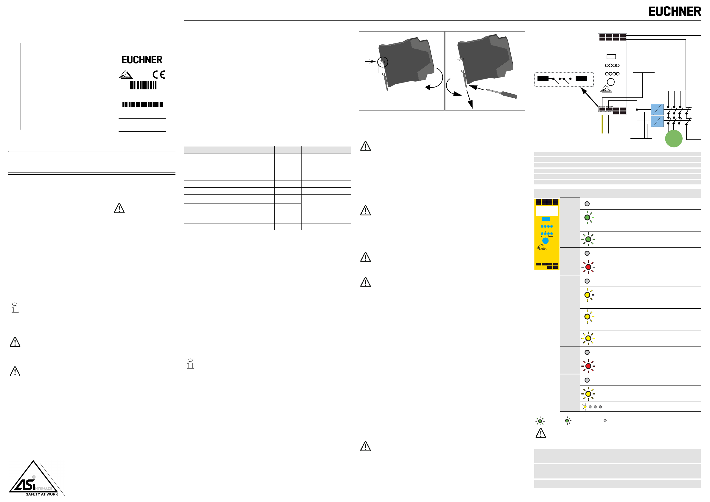
Montage Demontage
[1]
[3]
[2]
[1]
[2]
Die Montage des Moduls erfolgt auf 35 mm Normschienen nach
DIN EN 50 022.
Setzen Sie das Gerät zur Montage an der Oberkante der Normschiene an und
schnappen Sie es dann an der Unterkante ein.
Fachgerecht installieren:
Die elektrische Installation ist von eingewiesenem Fachpersonal durch-
zuführen. Bei der Installation ist darauf zu achten, dass Versorgungsund Signalleitungen und auch die AS-i-Busleitung getrennt von Kraftstromleitungen verlegt sind. Im Schaltschrank ist darauf zu achten, dass
bei Schützen eine entsprechende Funkenlöschung verwendet wird. Bei
Antriebsmotoren und -bremsen ist auf die Installationshinweise in den
entsprechenden Bedienungsanleitungen zu achten. Bitte beachten Sie,
dass die maximale Leitungslänge für die AS-i-Busleitung 100 m beträgt.
Darüber hinausgehende Leitungslängen erfordern den Einsatz
geeigneter Leitungsverlängerungen.
Halten Sie die vorgeschriebene Absicherung unbedingt ein, nur so ist
ein sicheres Abschalten im Fehlerfall gewährleistet.
Wartung
Die einwandfreie Funktion des AS-i-Safety-Relaisausgangsmoduls innerhalb
des absichernden Systems ist vom Sicherheitsbeauftragten mindestens jährlich
zu kontrollieren.
Dazu ist jeder sicherheitsgerichtete AS-i-Slave mindestens einmal pro
Jahr zu betätigen und das Schaltverhalten durch Beobachtung der Ausgangskreise des AS-i-Sicherheitsmonitors zu kontrollieren.
Abhängig vom für die Gesamtversagenswahrscheinlichkeit gewählten
PFD-Wert ist die maximale Einschaltdauer und die Gesamtbetriebsdauer zu beachten.
Bei Erreichen der maximalen Einschaltdauer (drei, sechs oder zwölf
Monate) ist die ordnungsgemäße Funktion des Sicherheitssystems
durch Anforderung der Abschaltfunktion zu überprüfen.
Bei Erreichen der Gesamtbetriebsdauer (20 Jahre) ist das Gerät vom
Hersteller auf seine ordnungsgemäße Funktion im Herstellerwerk zu
überprüfen.
Programmierung der sicherheitsrelevanten AS-i-Adresse
1. Den Schalter des Gerätes auf PRG stellen.
2. Die gewünschte Adresse mittels Hand-Adressiergerät oder AS-i-Master einstellen.
3. Die programmierte Adresse mittels Hand-Adressiergerät oder AS-i-Master kontrollieren.
4. Den ID-Code des Slaves mittels Hand-Adressiergerät oder AS-i-Master kontrollieren. Der Code soll „F“ sein.
5. Den ID1-Code des Slaves mittels Hand-Adressiergerät oder AS-i-Master kontrollieren. Der Code soll der Zehnerstelle der Adresse entsprechen.
6. Den ID2-Code des Slaves mittels Hand-Adressiergerät oder AS-i-Master kontrollieren. Der Code soll der Einerstelle der Adresse entsprechen.
7. Den IO-Code des Slaves mittels Hand-Adressiergerät oder AS-i-Master kontrollieren. Der Code soll „7“ sein.
8. Wenn alle Schritte von 3 bis 7 korrekt waren, kann weiter mit Schritt 9 fortgefahren
werden. Anderenfalls ab Schritt 1 wiederholen.
9. Den Schalter des Gerätes auf RUN stellen.
Die korrekte Sicherheitsfunktion des Gerätes muss unbedingt in der Anlage überprüft werden!
Programmierung der nicht-sicherheitsrelevanten AS-i-Adresse
Diese Adresse kann in der RUN-Position des Schalters mittels Hand-Adressiergerät
programmiert werden.
I –
I +
I +
1
I
RUN PRG
I +
2
3
I
I
1.Y1
L
1.141.13
I1, I2, I3
1.13, 1.14
1.23, 1.24
I-, I+
1.Y1
ASI+, ASI–
Aufkleber LEDs Status Signal / Beschreibung
I –
I +
I +
I +
I 1
I 2
I 3
1.Y1
Eingänge E1, E2 und E3
Ausgangskontaktsatz 1
Ausgangskontaktsatz 2
Versorgungsspannung für Eingänge
EDM (Eingang Rückführkreis)
Anschluss AS-i-Bus
ADDR
1.13
1.14
1.23
ASI –
1.24
NC
NC
ASI +
ASI+ ASI–
keine Betriebspannung
L1 L2 L3
1.Y1
K1
K2
I+
N
Motor
Betriebspannung vorhanden, sicherheitsrelevante
RUN PRG
1.Y1I 2
I 1I 3
FAULT ALARM
PWR
ADDR
PWR
grün
OUT
AS-i-Adresse und/oder AS-i-AB-Adresse ist „0“
1 Hz
Betriebspannung vorhanden
AS-i-Kommunikation OK
1.13
1.14
+
ASI
ASI
FAULT
1.23
1.24
rot
–
NC
NC
kein Datenaustausch mit dem AB-Slave
Ausgangsrelais ausgeschaltet
Wiederanlaufsperre, wartet auf Startsignal, nach
Startsignal schalten die Ausgangsrelais ein.
OUT
gelb
1 Hz
Das Gerät ist im entriegelbaren Fehlerzustand.
Wenn der Monitor das Signal "Fehlerentriegelung"
sendet, arbeitet das Gerät wieder normal.
8 Hz
Ausgangsrelais eingeschaltet
AS-i-Ausgangsbit A0 nicht gesetzt
ALARM
rot
AS-i-Ausgangsbit A0 gesetzt
Der entsprechende Eingang ist nicht geschaltet
I1, I2, I3,
1.Y1
Der entsprechende Eingang ist geschaltet
gelb
(Lauflicht) Schalter steht auf PRG
LED an LED blinkend LED aus
Blinken alle LEDs gleichzeitig im schnellen Rhythmus, hat das Gerät einen fatalen Fehler erkannt!!
Diese Meldung wird durch kurzzeitiges Trennen der Stromversorgung
(Power On Reset) zurückgesetzt.
PRG
sicherheitsrelevante AS-i-Adresse kann programmiert werden. Kein Schutzbetrieb
möglich
RUN
Schutzbetrieb möglich, nicht-sicherheitsgerichtete AS-i-Adresse kann programmiert
werden
ADDR
Adressierbuchse
Page 2
Page 3
SOM-4E-0A-C1
103489
AS-i Safety Relay
Output Module
0211310123450001
Euchner GmbH+Co.KG YoC: 2011
Kohlhammerstr. 16 70771 Leinfelden
AC-15, DC-13 3 A 30 V
Id.-No.: 103572 - Issue date: 2011-3-28 !
Subject to change without prior notice
Version No.: 13438
Safety Version: V4.1
FA.0001
Translation of the original operating instructions SOM-4E-0A-C1
Connecting instruction (abridged version)
"AS-i Safety Relay Output Module with Diagnostic
Slave and 1 EDM input"
Notes on using these connecting and operating instructions
This connecting and operating instruction contains information regarding the proper
and effective use of the AS-i Safety relay output module.
Safety precautions and warnings are designated by the symbol
EUCHNER GmbH + Co. KG is not liable for damage resulting from improper use
of its equipment. Familiarity with these instructions constitutes part of the
knowledge required for proper use.
© Reprint and reproduction, in whole or in part, only with the explicit permission of:
EUCHNER GmbH + Co. KG
Kohlhammerstraße 16 * D-70771 Leinfelden-Echterdingen!
Tel. +49(0)711/7597-0!
Fax +49(0)711/753316
Internet: http://www.euchner.de
This short description of the connection and operating instruction is a part of the
scope of delivery.
Specified normal operation of the module:
The AS-i Safety Relay Output Module is a decentralized output module
for safe control of actuators in the security bus system AS-i Safety at
Work (SaW).
For connection and commissioning of the SaW module the knowledge
is assumend of the connecting und operating instructions as well as operating instructions of ASIMON configuration and diagnostic software
(see accessories – ordering information).
Person protective function:
SaW modules integrated in the Safety bus systems AS-i safety at Work
fulfill a person protective function. Inappropriate installation puts the
function in risk! The manufacturer of the machine/plant at that one the
safety related devices is used is responsible for the correct and safe total function of all single safety components! Depending on the choice of
safety components to be used the safety system as a whole may also
be assigned to a lower safety category.
Application
The "AS-i Safety Relay Output Module with Diagnostic Slave and 1 EDM input" is a decentralized output module for safe control of actuators in the
safety bus system AS-i Safety at Work (SaW).
The module SOM-4E-0A-C1 is controlled by a safety monitor respectively a
gateway with integrated safety monitor.
A special characteristic of the module is its two types of AS-i addresses:
- Safe AS-i address!
SOM-4E-0A-C1 monitors to the communication on the safe address and switches based on the data listened in.
- Not safety-related AS-i address!
The not safety-related AS-i address is used for diagnosis and for PLC-controlled
switching.
All SaW output modules with the same safe AS-i adress are switching simultaneously.
The module SOM-4E-0A-C1 is certified according to EN 62 061, SIL 3 and
EN 13 849, Performance Level e.
Safety characteristics
Characteristics Value Standard
Safety category 4 EN 954-1
EN 13 849-1:2008
Performance Level (PL) e EN 13 849-1:2008
Safety Integrity Level (SIL) 3 IEC 61 508
Service life (TM) [year] 20 EN 13 849-1:2008
Maximal power-on time (month) 12 IEC 61 508
PFD
PFH
1
1
!
D
2 * 10
3,3 * 10
-5
IEC 61 508 EN 62 061
-9
(Probability of a dangerous loss per hour)
Max. system reaction time [ms] 50 IEC 61 508
1. The specified PFD and PFHD values refer to the maximum power-on time of
12 months and a maximum service life of 20 years, according to EN ISO 13 849-1.!
The maximum cycle time of the module (also under the assumption of errors) is
50 ms from the concern of the code sequence to the shutdown of the relay.!
In addition to the reaction time of the monitor and of the inputs must also be considered.
Safety Requirements
• In the device two relays connected in series and positively-driven are used.
• If one of the two relays is not switching (e.g. for stuck contact), the module will recognize this.
• The contact sets 1.13/1.23 and 1.14/1.24 are realized with the same relays and not
independent.
• 1.13, 1.23, 1.14, 1.24 are potential-free contacts without cross-circuit monitoring.
• If two independent contactors connected in series are to be controlled with the device, it is to be ensured that the line between the contactors and the device can get
no connection to another potential to prevent an unwanted switching-on of the contactors.
• The input 1.Y1 is – as well I1 ... I3 – a standard AS-i input.
Control and indicating elements, configuration
See <data sheetSOM-4E-0A-C1> and <manual ASIMON configuration software>.
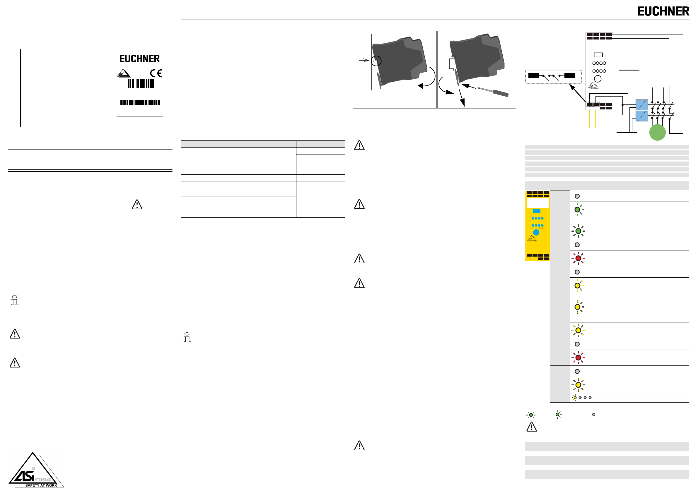
Assembling Disassembling
[1]
[3]
[2]
[1]
[2]
The module is mounted on 35 mm standard rails acc. to DIN EN 50 022.
For assembling, position the device on the upper edge of the standard rail and
snap it onto the bottom edge then.
Ensure appropiate installation:
Electrical installation is to be performed by trained expert personnel.
During installation care must be taken that supply and signal leads and
also the AS-i bus cable are laid separately from power cables. In the
switchgear cabinet it must be ensured that appropriate spark-quenching
equipment is used with contactors. Where drive motors and brakes are
used, attention must be paid to the installation instructions in the corresponding operating instructions. Please note that the maximum line
length of the AS-i bus cable is 100 m. Cables above that length require
the use of a suitable circuit extension.
It is essential to adhere to the prescribed fusing; this is the only way of
guaranteeing safe disconnection in the case of a fault.
Maintenance
The proper function of the AS-i Safety Relay Output Module within the system to
be secured, i.e. the safe shutdown following the triggering of an assigned safe
sensor or switch, is to be checked at least annually by the safety officer.
This is to be performed by activating each safe AS-i slave at least once
per year and visually inspecting the switching behaviour of the output
circuits of the AS-i safety monitor.
The maximum switch-on time and total operating time depends on the
PFD value selected for the overall failure probability.
When the maximum switch-on time has been reached (three, six or
twelve months), the safety system must be checked to ensure that it is
functioning correctly by prompting the shutdown function.
When the total operating time has been reached (20 years), the device
must be checked at the manufacturer's factory to ensure that it is functioning correctly.
Programming of the safety-related AS-i address
1. Move the switch of the device to PRG.
2. Set the requested address using a handheld programming device or an AS-i master.
3. Check the programmed address using a handheld programming device or an AS-i
master.
4. Check the ID code of the slave using a handheld programming device or an AS-i
master. The code should be „F“.
5. Check the ID1 code of the slave using a handheld programming device or an AS-i
master. The code should correspond to the tens digit of the address.
6. Check the ID2 code of the slave using a handheld programming device or an AS-i
master. The code should correspond to the digit of the address.
7. Check the IO code of the slave using a handheld programming device or an AS-i
master. The code should be „7“.
8. If all the steps from 3 to 7 were correctly, please continue with step 9. Otherwise
repeat from step 1 again.
9. Move the switch of the device to RUN.
The proper safety function of the device must be verified in the asset in
any case!
Programming of the not safety-related AS-i address
The address can be set using a handheld programming device in RUN-position of the
switch.
–
+
+
+
I
I
I
I
I
I
I
1.Y1
1
2
3
RUN PRG
L
I1, I2, I3
1.13, 1.14
1.23, 1.24
I-, I+
1.Y1
ASI+, ASI–
1.141.13
standard inputs I1, I2 and I3
safety output contact set 1
safety output contact set 2
supply voltage for inputs
EDM (input for electronic device monitoring)
AS-i network connection
ADDR
1.13
1.14
1.23
+
–
NC
ASI
ASI
ASI+ ASI–
L1 L2 L3
1.24
NC
K1
1.Y1
K2
I+
N
Motor
Label LEDs State Signal / description
I –
I +
I +
I +
I 1
I 2
I 3
1.Y1
no operating voltage
operating voltage present, safety-related AS-i
RUN PRG
1.Y1I 2
I 1I 3
FAULT ALARM
PWR
ADDR
PWR
green
OUT
address and/or AS-i AB address is „0“
1 Hz
operating voltage present
AS-i communication OK
1.13
1.14
+
ASI
ASI
FAULT
1.23
1.24
red
–
NC
NC
no data exchange with AB slave
output relays contacts open
restart inhibit, waiting for the start signal, the output
relays switch-on after the start signal
OUT
yellow
1 Hz
device is in unlockable error state.!
Waiting for "reset of error condition signal". After
receiving this signal the device follows up with nor-
8 Hz
mal operation.
output relays contacts closed
AS-i output bit A0 is not set
ALARM
red
AS-i output bit A0 is set
the corresponding input is not connected
I1, I2, I3,
1.Y1
the corresponding input is connected
yellow
(running light) switch is adjust to PRG position
LED on LED flashing LED off
In case all LEDs are blinking simultaneously in fast rythm a fatal error
has been detected.!
This message is reset by a short-run disconnection of the power supply
(Power On Reset).
PRG
protective mode not possible. Programming of safety-related AS-i addresse enabled.
RUN
protective mode possible. Programming of not safety-related AS-i addresse enabled
ADDR
addressing socket
Page 4

Page 5

SOM-4E-0A-C1
103489
AS-i Safety Relay
Output Module
0211310123450001
Euchner GmbH+Co.KG YoC: 2011
Kohlhammerstr. 16 70771 Leinfelden
Id.-No.: 103572 - Edition: 2011-3-28 !
Sous réserve de modifications techniques
AC-15, DC-13 3 A 30 V
Version No.: 13438
Safety Version: V4.1
FA.0001
Traduction des instructions de service originales SOM-4E-0A-C1
Instructions de raccordement (Version abrégée)
"Module de sortie de relais de sécurité AS-i avec esclave de diagnostic et 1 entrée EDM"
Remarques pour l’utilisation des instructions de raccordement et
de service
Ces instructions de raccordement et de service contiennent des informations sur l’utilisation conforme et effective du module de sortie de relais de sécurité AS-i.
Les avertissements sont caractérisés par le symbole suivant .
EUCHNER GmbH + Co. KG dégage toute responsabilité en cas de dommages
liés à une utilisation non conforme. L’utilisation appropriée implique d’avoir lu
et assimilé ces instructions.
© La réimpression ou reproduction en tout ou partie ne peut être faite sans l’agrément
préalable de:
EUCHNER GmbH + Co. KG
D-70771 Leinfelden-Echterdingen!
Tel. +49(0)711/7597-0!
Fax +49(0)711/753316
Internet: http://www.euchner.de
Cette version abrégée des instructions de raccordement et de service est incluse
dans la livraison.
Utilisation conforme du module:
Le module AS-i avec sorties relais de sécurité est un module de sortie
décentralisé pour le contrôle sécurisé des actionneurs dans le système
de bus AS-i Safety at Work (SaW).
Pour brancher et mettre en service le module SaW, il est impératif de
connaître les instructions de raccordement et de service ainsi que le manuel d’utilisation du logiciel de configuration et de diagnostic ASIMON
(voir accessoires).
Fonction de protection des personnes:
Les modules intégrés dans le système de bus SaW remplissent une
fonction de protection des personnes. Le montage non conforme endommage sa fonction! Le fabricant d’une machine/installation, sur laquelle le système de sécurité est installé, est responsable du
fonctionnement d’ensemble correct et sûr de tous les composants de
sécurité! Suivant le choix des composants de sécurité, le système de
sécurité dans son ensemble peut être classé dans une catégorie de sécurité inférieure!
Domaines d’application
Le "Module de sortie de relais de sécurité AS-i avec esclave de diagnostic
et 1 entrée EDM" est un module de sortie décentralisé pour le contrôle
sécurisé des actionneurs dans le système de bus AS-i Safety at Work
(SaW).
Le module SOM-4E-0A-C1 est piloté par un moniteur de sécurité ou bien une
passerelle avec moniteur de sécurité intégré.
Il se distingue surtout par ses deux sortes d’adresses AS-i:
- Adresse AS-i orientée sécurité!
SOM-4E-0A-C1 surveille la communication sur l’adresse de sécurité et commande sur la base des données obtenues.
- Adresse AS-i non relative à la sécurité!
L’adresse AS-i non relative à la sécurité sert à la diagnostic et à la commutation
fonctionnelle contrôlée par l’API.
Tous les modules SaW ayant la même adresse de sécurité AS-i sont contrôlés
simultanément.
Le module SOM-4E-0A-C1 est certifié selon EN 62 061, SIL 3 et EN 13 849,
niveau de performance e.
Caractéristique de sécurité
Caractéristiques Valeu r Standard
Catégorie de sécurité 4 EN 954-1
EN 13 849-1:2008
Performance Level (PL) e EN 13 849-1:2008
Safety Integrity Level (SIL) 3 IEC 61 508
Durée de service (TM) [années] 20 EN 13 849-1:2008
Durée de marche maximale [mois] 12 IEC 61 508
PFD
PFH
1
1
!
D
2 * 10
3,3 * 10
-5
-9
IEC 61 508
EN 62 061
(Probabilité d’une panne dangereuse par heure)
Temps de réaction max. du système [ms] 50 IEC 61 508
1. Les valeurs PFD et PFHD indiquées se réfèrent à une durée de marche maximale
durée de service maximale de 20 années selon EN ISO 13 849-1.!
Le temps de commutation maximale du module (tout en considérant des erreurs)
s’élève à 50 ms dès la génération des sequences de code jusqu’à la coupure du
relais.!
Il faut également tenir compte du temps de réponse du moniteur et des entrées.
Exigences de sécurité
• Deux relais forçes et connectés en parallèle sont utilisés dans le boîtier.
• Si un des deux relais ne commute pas (p. ex. en cas des soudures des contacts),
le module le détectera.
• Les couples de contacts 1.13/1.23 et 1.14/1.24 sont réalisés avec le même relais
et ne sont pas indépendants.
• Les contacts 1.13, 1.23, 1.14, 1.24 sont libres de potentiels. Un contrôle des défaillances entre les deux circuits d’arrêt d’urgence (crossfault monitoring) n’existe
pas.
• Si deux contacteurs indépendants, connectés en série, doivent être contrôlés avec
cet appareil, il faut assurer que la ligne entre les contacteurs et l’appareil n’a pas
de connexion à d’autres potentiels pour éviter l’enclenchement non désiré des
contacteurs.
• L’entrée 1.Y1 est – comme également I1 ... I3 – une entrée AS-i standard.
Eléments de commande et d’affichage, configuration
Voir à ce propos <fiche techniqueSOM-4E-0A-C1> et <manuel du
logiciel de configuration ASIMON>.
Montage Démontage
[1]
[3]
[2]
[1]
[2]
Le module AS-i avec sorties relais de sécurité AS-i est prévu pour un montage sur
rails normalisés (35 mm) selon DIN EN 50022.
Pour monter l’appareil, l’appuyer fermement contre la partie supérieure du profilé et
le clipser sur la partie inférieure.
Conseils pour l’installation électrique:
L’installation électrique sera effectuée par du personnel qualifié et informé. Lors de l’installation, veiller à poser les câbles d’alimentation et de
signaux ainsi que le câble bus AS-i séparément des câbles d’énergie.
Dans l’armoire technique, prendre soin d’équiper les contacteurs de dispositifs d’antiparasitage. Pour les moteurs et les freins, respecter les indications figurant dans les instructions de services respectives.
Remarque: la longueur maximale du câble AS-i est de 100 m. Pour les
longueurs supérieures, il faudra monter dans la ligne un répéteur AS-i.
Respectez impérativement le calibre de protection prescrit; ce n’est qu’à
cette condition que la coupure sûre est assurée en cas de défaut.
Maintenance
Le fonctionnement parfait du moniteur de sécurité AS-i au sein du système de sécurité, c’est à dire la coupure fiable du système en cas de déclenchement d’un des capteurs ou interrupteurs de sécurité sous la dépendance du moniteur doit faire l’objet
d’un contrôle au minimum annuel.
Pour ce faire, actionner au moins une fois par an, chaque esclave AS-i
affecté à la sécurité et contrôler le comportement du système au niveau
des sorties de sécurité du moniteur de sécurité AS-i.
Il faut observer la durée de marche et la durée totale de service maximale en fonction de la valeur PFD calculée pour la probabilité de défaillance.
Lorsque la durée de marche maximale est atteinte (3, 6 ou 12 mois), il
faut contrôler le fonctionnement correct du système de sécurité en déclenchant la fonction d’arrêt.
Lorsque la durée totale de service est atteinte (10 ans), l’appareil doit
être examiné en vue de son fonctionnement correct par le fabriquant.
Programmation de l’adresse AS-i orientée sécurité
1. Mettre l’interrupteur de l’appareil en position PRG.
2. Configurer l’adresse souhaitée via terminal d’adressage ou maître AS-i.
3. Contrôler l’adresse configurée via terminal d’adressage ou maître AS-i.
4. Contrôler le code ID de l’esclave via terminal d’adressage ou maître AS-i. Le code
doit être “F“.
5. Contrôler le code ID1 de l’esclave via terminal d’adressage ou maître AS-i. Il code
doit correspondre au chiffre des dizaines de l’adresse.
6. Contrôler le code ID2 de l’esclave via terminal d’adressage ou maître AS-i. Il code
doit correspondre au chiffre des unités de l’adresse.
7. Contrôler le code IO de l’esclave via terminal d’adressage ou maître AS-i. Le code
doit être “7“.
8. Si les pas de 3 à 7 ont été executés correctement, continuer avec pas 9 s.v.p., !
sinon répéter les pas de 1 à 7.
9. Mettre l’interrupteur de l’appareil en position RUN.
Vérifier le fonctionnement correct de la fonction de sécurité de cet appareil dans l’installation !
Programmation de l’adresse AS-i non relative à la sécurité
L’adresse peut être configurée en position RUN de l’interrupteur à l’aide d’un terminal
d’adressage.
I –
I +
I +
I
1
RUN PRG
I +
I
I
1.Y1
2
3
L
1.141.13
I1, I2, I3
1.13, 1.14
1.23, 1.24
I-, I+
1.Y1
ASI+, ASI–
Autocollant LED Etat Signal / Description
I –
I +
I +
I +
I 1
I 2
I 3
1.Y1
entrées E1, E2 et E3
plots de contact de sortie 1
plots de contact de sortie 2
tension d’alimentation pour les entrées
EDM (entrée circuit feedback)
raccordement au bus AS-i
ADDR
ASI –
1.24
1.14
1.23
NC
NC
1.13
ASI +
ASI+ ASI–
N
pas de tension de fonctionnement
K1
K2
L1 L2 L3
Motor
1.Y1
I+
tension de fonctionnement présente, adresse AS-i
RUN PRG
1.Y1I 2
I 1I 3
FAULT ALARM
PWR
ADDR
PWR
verte
OUT
orienté sécurité et/ou adresse AB AS-i est de “0“
1 Hz
tension de fonctionnement présente
communication AS-i OK
1.13
1.14
+
ASI
ASI
FAULT
1.23
1.24
rouge
–
NC
NC
pas d’échange de données avec l’esclave AB
relais de sortie éteint
blocage de redémarrage actif, attend le signal Start,
les relais de sortie sont mis en marche après le
signal Start
OUT
jaune
1 Hz
l’appareil se trouve dans un état d’erreurs déverrouillable. Lorsque le moteur envoie le signal "déverrouillage des erreurs“, l’appareil fonctionne de
8 Hz
nouveau normalement.
relais de sortie en marche
bit de sortie AS-i A0 n’est pas mis
ALARM
rouge
bit de sortie AS-i A0 est mis
l’entrée correspondante n’est pas raccordée
I1, I2, I3,
1.Y1
l’entrée correspondante est raccordée
jaune
(feu fixe) commutateur se trouve sur PRG
LED an LED clignotante LED éteinte
Lorsque toutes les LED clignotent simultanément à fréquence élevée,
l’appareil a détecté une Fatal Error!!
Ce message est remis par une brève disjonction de l’alimentation (Power On Reset).
PRG
mode de protection non possible, l’adresse AS-i orientée sécurité peut être configurée
RUN
mode de protection possible, l’adresse AS-i non relative à la sécurité peut être configurée
ADDR
prise d’adressage
Page 6

Page 7

SOM-4E-0A-C1
103489
AS-i Safety Relay
Output Module
0211310123450001
Euchner GmbH+Co.KG YoC: 2011
Kohlhammerstr. 16 70771 Leinfelden
AC-15, DC-13 3 A 30 V
Id.-No.: 103572 - Edizione: 2011-3-28 !
Con riserva di modifiche senza preavviso
Version No.: 13438
Safety Version: V4.1
FA.0001
Traduzione delle istruzioni per l'uso originali SOM-4E-0A-C1
Istruzioni per il collegamento (supplemento)
"Modulo di uscita relè di sicurezza AS-i con slave di
diagnostica e 1 ingresso EDM"
Avvisi per l’utente delle istruzioni per il collegamento e l’uso
Queste istruzioni per il collegamento e l’uso contengono informazioni importanti all’impiego efficace e conforme alla destinazione d’uso del modulo di uscita relè di sicurezza AS-i.
Le avvertenze di sicurezza sono indicate con il simbolo .
EUCHNER GmbH + Co. KG declina ogni responsabilità per danni dovuti ad un
uso inadeguato. Di un impiego appropriato del monitor di sicurezza AS-i fa parte anche la conoscenza delle istruzioni per il collegamento e per l’uso.
© Stampa e riproduzione vietata, anche in forma di estratto, se non dietro esplicito
permesso della:
EUCHNER GmbH + Co. KG
Kohlhammerstraße 16 * D-70771 Leinfelden-Echterdingen!
Tel. +49(0)711/7597-0!
Fax +49(0)711/753316
Internet: http://www.euchner.de
Questo supplemento delle istruzioni per il collegamento e l’uso costituisce parte integrante della fornitura.
Uso appropriato del modulo:
Il modulo AS-i con uscite relè di sicurezza è un modulo di uscita decentrato per il controllo sicuro di attuatori nel sistema bus AS-i Safety at
Work (SaW).
Per l’allacciamento e la messa in servizio del modulo di sicurezza è imperativo conoscere le istruzioni per il collegamento e l’uso ed anche il
manuale d’uso del software di configurazione e di diagnostica ASIMON
(vedere accessori).
Funzione di protezione degli operatori:
I moduli integrati nel sistema bus SaW svolgono una funzione di protezione degli operatori. Un’installazione inadeguata può causare gravi lesioni alle persone. Il costruttore di una macchina o di un impianto è
risponsabile del funzionamento corretto e sicuro di tutti i componenti di
sicurezza! In funzione della scelta dei componenti di sicurezza utilizzati,
l’intero sistema di sicurezza può anche essere inserito in una categoria
inferiore!
Campi di impiego
Il "Modulo di uscita relè di sicurezza AS-i con slave di diagnostica e 1 ingresso EDM" è un modulo di uscita decentrato per il controllo sicuro di attuatori nel sistema bus AS-i Safety at Work (SaW).
Il modulo SOM-4E-0A-C1 viene controllato da un monitor di sicurezza o da un
gateway con monitor di sicurezza integrato.
Il modulo è caratterizzato dai suoi due tipi di indirizzi AS-i:
- Indirizzo AS-i orientato alla sicurezza!
SOM-4E-0A-C1 sorveglia la comunicazione sull’indirizzo di sicurezza e commuta sulla base dei dati così ottenuti.
- Indirizzo AS-i non relativo alla sicurezza!
L’indirizzo AS-i non relativo alla sicurezza è utilizzato per la diagnostica e per il
comando funzionale controllato da PLC.
Ogni modulo di uscita SaW con lo stesso indirizzo di sicurezza AS-i vengono
controllati simultaneamente.
Il modulo SOM-4E-0A-C1 viene certificato secondo EN 62 061, SIL 3 e
EN 13 849, Performance Level e.
Caratteristiche di sicurezza
Caratteristiche Valor e Standard
Safety category 4 EN 954-1
EN 13 849-1:2008
Performance Level (PL) e EN 13 849-1:2008
Safety Integrity Level (SIL) 3 IEC 61 508
Durata di esercizio (TM) [anni] 20 EN 13 849-1:2008
Durata max. dell’inserzione [mesi] 12 IEC 61 508
PFD
PFH
1
1
!
D
2 * 10
3,3 * 10
-5
IEC 61 508 EN 62 061
-9
IEC 61 508 EN 62 061
(Probabilità di un guasto pericoloso all’ora)
Tempo max. di reazione del sistema [ms] 50 IEC 61 508
1. I valori PFD e PFHD indicati si riferiscono a una durata max. dell’inserzione di
12 mesi ed a una durata max. di esercizion di 20 anni secondo EN ISO 13 849-1.!
Il tempo di commutazione max. del modulo (anche considerando possibili errori) è
di 50 ms dall’inserimento della sequenza di codice fino allo spegnimento del relè.!
In aggiunta a ciò, il tempo di risposta del monitor e degli ingressi deve anche essere
preso in considerazione.
Esigenze di sicurezza
• Due relè forzati e collegati in serie vengono utilizzati nella custodia.
• Se uno dei due relè non commuta (p. es. nel caso di saldatura dei contatti), !
il modulo lo riconoscerà.
• I set di contatti 1.13/1.23 e 1.14/1.24 vengono realizzati con gli stessi relè, quindi
non sono indipendenti.
• 1.13, 1.23, 1.14, 1.24 sono contatti privi di potenziale senza controllo di crossfault.
• Se due contattori indipendenti e collegati in serie devono essere controllati con l’apparecchio, bisogna assicurarsi che la linea fra contattori e apparecchio non ha nessuna connessione ad altri potenziali per impedire una inserzione non desiderata dei
contattori.
• L’ingresso 1.Y1 è – come anche I1 ... I3 – un ingresso AS-i standard.
Elementi di comando e di visualizzazione, configurazione
Vedere a questo proposito <scheda tecnicaSOM-4E-0A-C1> e
<manuale del software di configurazione ASIMON >.
Montaggio Smontaggio
[1]
[3]
[2]
[1]
[2]
L’installazione del modulo avviene agganciandolo ad una guida ad installazione rapida da 35 mm secondo DIN EN 50 022.
Per montare il monitor esercitare una certa pressione sulla parte superiore della guida
e inserirlo a scatto nella parte inferiore.
Avvertenze relative all’installazione elettrica:
L’installazione elettrica deve essere eseguita da peronale tecnico qualificato. Durante l’installazione è necessario che i conduttori di alimentazione e dei segnali così come il cavo di bus AS-Interface vengano stesi
separatemente dai cavi di potenza. Nell’armadio di comando occorre
fare attenzione a che sui contattori vengono utilizzati dispositivi spegniscintille. Per i motori dei freni e degli azionamenti occorre rispettare le
avvertenze di installazione contenute nelle corrispondenti istruzioni di
servizio.Fare attenzione a che la massima lunghezza di cavo per il bus
AS-i sia di 100 m. Lunghezze di cavo maggiori richiedono l’impiego di
un repeater AS-i.
Rispettare assolutamente la protezione prescritta, solo così in caso di
guasto è garantita una disinserzione sicura.
Manutenzione
Il corretto funzionamento del monitor di sicurezza AS-i nell’ambito del sistema di sicurezza, ovvero la disattivazione sicura in caso di disinserimento di un sensore assegnato , deve essere sottoposto a controllo a cadenza annuale da parte del personale
adetto.
Per questo è necessario azionare gli slave di sicurezza AS-i almeno una
volta l’anno e controllare il comportamento del sensore tramite osservazione delle uscite di sicurezza del monitor di sicurezza AS-i.
Tenere conto della durata della inserzione e della durata complessiva di
esercizio in funzione del valore PFD calcolato per la probabilità di guasto.
Quando la durata della inserzione è raggiunta (3, 6 ou 12 mesi), si deve
controllare il funzionamento corretto del sistema di sicurezza attivando
la funzione di arresto di emergenza.
Quando la durata complessiva di esercizio è raggiunta (10 anni), l’apparecchio deve essere esaminato dal fabbricante in vista di un funzionamento corretto.
Configurazione dell’indirizzo AS-i orientato alla sicurezza
1. Mettere l’interruttore dell’apparecchio in posizione PRG.
2. Impostare l’indirizzo desiderato tramite un dispositivo di indirizzamento o di un
master AS-i.
3. Controllare l’indirizzo configurato tramite un dispositivo di indirizzamento o di un
master AS-i.
4. Controllare il codice ID dello slave tramite un dispositivo di indirizzamento o di un
master AS-i. Il codice deve essere „F“.
5. Controllare il codice ID1 dello slave tramite un dispositivo di indirizzamento o di un
master AS-i. Il codice deve corrispondere alla cifra delle decine dell’indirizzo.
6. Controllare il codice ID1 dello slave tramite un dispositivo di indirizzamento o di un
master AS-i. Il codice deve corrispondere alla cifra delle unità dell’indirizzo.
7. Controllare il codice IO dello slave tramite un dispositivo di indirizzamento o di un
master AS-i. Il codice deve essere „7“.
8. Se tutti i passi da 3 a 7 sono stati eseguiti correttamente, continuare con passo 9.
Altrimenti, ripetere dal passo 1.
9. Mettere l’interruttore dell’apparecchio in posizione RUN.
Il funzionamento corretto della funzione di sicurezza deve assolutamente essere verificato nell’impianto!
Configurazione dell’indirizzo AS-i non relativo alla sicurezza
L’indirizzo può essere impostato tramite un dispositivo di indirizzamento in posizione
RUN dell’interruttore.
I –
I +
I +
I
1
RUN PRG
I +
I
I
1.Y1
2
3
L
1.141.13
I1, I2, I3
1.13, 1.14
1.23, 1.24
I-, I+
1.Y1
ASI+, ASI–
Adesivo LED Stato Segnale / descrizione
I –
I +
I +
I +
I
I
I
1.Y1
1
2
3
ingressi I1, I2 e I3
set di contatti di sicurezza 1
set di contatti di sicurezza 2
tensione di alimentazione per gli ingressi
EDM (ingresso circuito feedback)
Collegamento al bus AS-i
ADDR
ASI –
1.24
1.14
1.23
NC
NC
1.13
ASI +
ASI+ ASI–
N
nessuna tensione di funzionamento
K1
K2
L1 L2 L3
Motor
1.Y1
I+
tensione di funzionamento presente, indirizzo AS-i
RUN PRG
1.Y1I 2
I 1I 3
FAULT ALARM
PWR
ADDR
PWR
verde
OUT
orientato alla sicurezza e/0 indirizzo AS-i AB è “0“
1 Hz
tensione di funzionamento presente
comunicazione AS-i OK
1.13
1.14
+
ASI
ASI
FAULT
1.24
1.23
rosso
–
NC
NC
nessuno scambio dati con lo slave AB
relè di uscita spento
blocco riavviamento attivo, aspettando il segnale
Start, i relè di uscita vengono commutati dopo il
segnale Start
OUT
giallo
1 Hz
l’apparecchio è in stato di errore sbloccabile.
Quando il motore invia un segnale "sblocco di
errori", l’apparecchio funziona di nuovo nor-
8 Hz
malmente.
relè di uscita è commutato
bit di uscita AS-i A0 non è messo
ALARM
rosso
bit di uscita AS-i A0 è messo
l’ingresso corrispondente non è collegato
I1, I2, I3,
1.Y1
l’ingresso corrispondente è collegato
giallo
(giallo continuo) commutatore si trova su PRG
LED on LED lampeggiante LED off
Quando i LED lampeggiano rapidamente e simultaneamente, l’apparecchio ha rivelato un Fatal Error!!
Questo messaggio è resettato con una breve disconnessione dell’alimentazione (Power On Reset).
PRG
modo di protezione non è possibile, indirizzo AS-i orientato alla sicurezza può essere
configurato
RUN
modo di protezione è possibile, indirizzo AS-i non relativo alla sicurezza può essere
configurato
ADDR
presa di indirzzamento
Page 8

 Loading...