

Page 1
Betriebsanleitung Präzisions-Reihengrenztaster GL, GS, SB, SN 8 mm
D R K
R
4
R
4
120
-5°
1 24
1
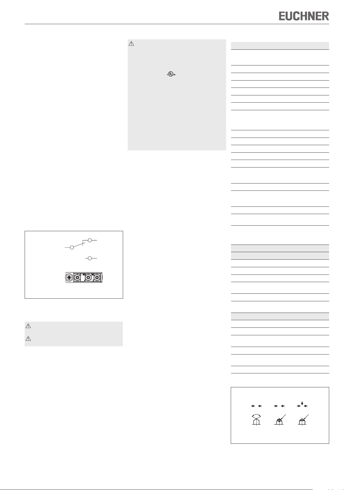
4 (NO)
2 (NC)
(C)
Bestimmungsgemäßer Gebrauch
Präzisions-Reihengrenztaster werden zum Positionieren und Steuern von Maschinen und Industrieanlagen
eingesetzt.
Zum bestimmungsgemäßen Gebrauch gehört das
Einhalten der einschlägigen Anforderungen für den
Einbau und Betrieb, insbesondere
EN 60204-1, Elektrische Ausrüstung von Ma-
schinen
EN 1050, Sicherheit von Maschinen, Risikobe-
urteilung.
Nicht bestimmungsgemäßer Gebrauch
Präzisions-Reihengrenztaster mit Schaltelement
ES 552 und ES 614 (Sprungschaltglieder ohne
Zwangstrennung) dürfen nicht in Sicherheitsschaltkreisen eingesetzt werden.
Funktion
Präzisions-Reihengrenztaster besitzen mehrere
Schaltelemente, die in einer Reihe angeordnet
sind.
Die Schaltelemente werden über Stößel betätigt. Entsprechend der Anwendung (Schaltpunktgenauigkeit
und Anfahrgeschwindigkeit) werden verschiedene
Stößel und Steuernocken eingesetzt.
Das Betätigen der Stößel erfolgt durch Steuernocken, die in Nutenprofilen kraftschlüssig befestigt
sind.
Das Baujahr des Schalters ist aus dem Fertigungscode ersichtlich.
Schaltelemente / Anschlussbelegung
ES 552
ES 614
Draufsicht
auf das Schaltelement
Bild 1: Schaltelemente und Anschlussbelegung
Montage
Die Montage darf ausschließlich von autorisiertem Fachpersonal durchgeführt werden.
Präzisions-Reihengrenztaster dürfen nicht als
Anschlag verwendet werden.
Präzisions-Reihengrenztaster so anbauen, dass
Anschlussleitungen und Steckverbinder nicht von
bewegten Maschinenteilen beschädigt werden
bei Leitungseinführung durch den Sockel die
Dichtheit gewährleistet ist.
Schutz vor Umgebungseinflüssen
Entlüftungsventile dienen dem Druckausgleich gegen
Pumpwirkung der Stößel. Sie dürfen nicht mit Farbe
verschlossen werden.
Bei Lackierarbeiten Stößel, Stößelführung, Entlüf-
tungsventile und Typenschild abdecken!
Elektrischer Anschluss
Der elektrische Anschluss darf ausschließlich
von autorisiertem Fachpersonal durchgeführt
werden.
Für Schalter mit UL-Zulassung gilt:
Für den Einsatz und die Verwendung gemäß den
Anforderungen von muss eine class 2 Spannungsversorgung oder ein class 2 Transformator
nach UL1310 oder UL1585 verwendet werden.
Am Einsatzort installierte Anschlussleitungen von
Präzisions-Reihengrenztastern müssen räumlich
von beweglichen und fest installierten Leitungen und
nicht isolierten aktiven Teilen anderer Anlagenteile,
die mit einer Spannung von über 150 V arbeiten,
so getrennt werden, dass ein ständiger Abstand
von 50,8 mm eingehalten wird. Es sei denn, die
beweglichen Leitungen sind mit geeigneten Isoliermaterialien versehen, die eine gleiche oder höhere
Spannungsfestigkeit gegenüber den andereren
relevanten Anlagenteilen besitzen.
Schalterdeckel öffnen
Leiterquerschnitt 0,14 ... 1,0 mm²
Anschlussbelegung siehe Bild 1
Passende Kabelverschraubung mit gefasstem
O-Ring montieren
Leitung sorgfältig abdichten. Dichtring muss auf
den Leitungsdurchmesser abgestimmt sein
Anschlussschrauben der Schaltelemente mit
0,2 Nm anziehen
Schalterdeckel schließen und Deckelschrauben
mit 0,5 Nm anziehen.
Funktionsprüfung
Mechanische Funktionsprüfung
Stößel betätigen und die Schaltfunktionen über
prüfen.
Elektrische Funktionsprüfung
Korrekten Funktionsablauf prüfen.
Wartung und Kontrolle
Wartungsarbeiten sind nicht erforderlich. Um eine einwandfreie und dauerhafte Funktion zu gewährleisten,
sind regelmäßige Kontrollen erforderlich auf
einwandfreie Schaltfunktion
sichere Befestigung der Bauteile
Präzise Justierung von Steuernocken zu Reihen-
grenztaster
Ablagerungen und Verschleiß
Dichtheit der Kabeleinführung
gelockerte Leitungsanschlüsse.
Haftungsausschluss bei
nicht bestimmungsgemäßem Gebrauch
Nichteinhalten der Sicherheitshinweise
Anbau und elektrischem Anschluss nicht durch
autorisiertes Fachpersonal
nicht durchgeführten Funktionskontrollen.
Technische Daten
Parameter Wert
Gehäusewerkstoff
Baureihe GL, GS
SB, SN
Stößelwerkstoff Stahl, rostfrei
Schutzart nach IEC 60529 IP 67
Mechanische Schaltspiele 30 x 10
Betätigungshäufigkeit ≤ 200 min
Umgebungstemperatur -5 ... +80 °C
Einbaulage beliebig
Anfahrgeschwindigkeit max.
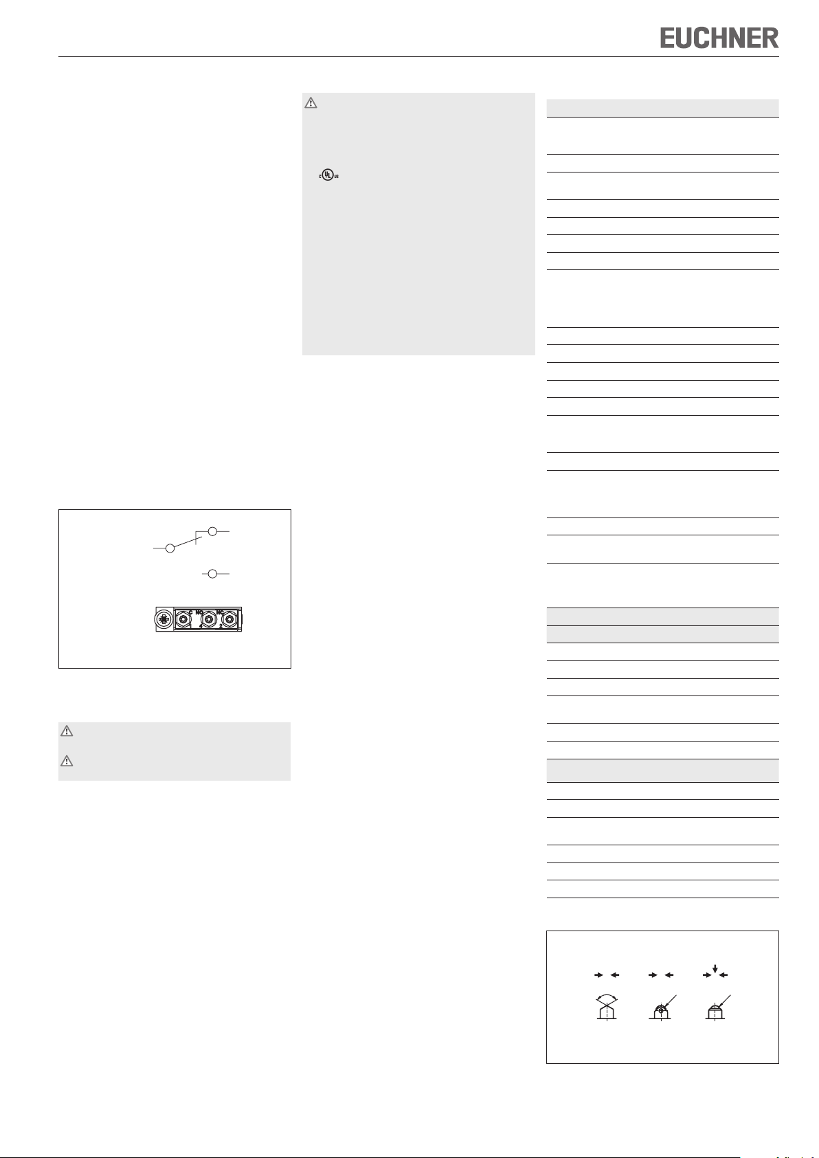
Stößel Dach D
Rollen R (Gleitlager)
Kugel K
Anfahrgeschwindigkeit min. 0,01 m/min
Betätigungskraft ≥ 15 N
Schaltelement 1 Wechsler
Schaltprinzip Sprungschaltglied
Schalthysterese max. 0,1 mm
Kontaktwerkstoff
ES 552
ES 614
Anschlussart Schraubanschluss
Anzugsdrehmoment
Schraubanschluss
(Innensechskant SW 1,27 mm)
Leiterquerschnitt 0,14 ... 1,0 mm
Bemessungsstoßspannungsfestigkeit
Bemessungsisolationsspannung
mit Kabeleinführung
-
mit Steckverbinder
Bemessungsdaten der Schaltelemente
ES 552
Konv. thermischer Strom Ith6 A
Gebrauchskategorie AC-15 230 V / 2 A
Gebrauchskategorie DC-13 24 V / 2 A
Schaltstrom min. bei
Schaltspannung
Kurzschlussschutz 6 A gG
Mechanische Lebensdauer bis 10 x 106 Betätigungs-
ES 614
Konv. thermischer Strom Ith2 A
Gebrauchskategorie DC-13 30 V / 1 A
Schaltstrom min. bei
Schaltspannung
Kurzschlussschutz 2 A gG
Mechanische Lebensdauer bis 10 x 106 Betätigungs-
Idealer Einsatzbereich 1 mA; 5 V ... 0,3 A; 30 V
Bevorzugte Anfahrrichtungen
Aluminium-Sandguss, eloxiert
Aluminium-Druckguss, eloxiert
6
-1
20 m/min
50 m/min
8 m/min
Silber
Gold-Kreuzschneiden-Kontakte
0,2 Nm
U
= 2,5 kV
imp
Ui = 250 V
Ui = 50 V
10 mA
DC 24 V
zyklen
1 mA
DC 5 V
zyklen
2
Bild 2: Stößel und Anfahrrichtungen
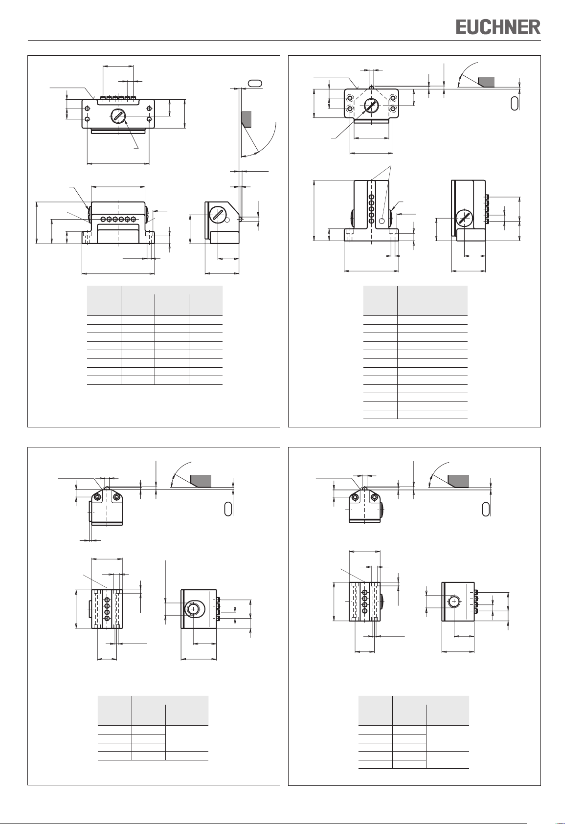
Page 2

Betriebsanleitung Präzisions-Reihengrenztaster GL, GS, SB, SN 8 mm
8
n
12
14
l
2
22
38
l
3
16
32
55
10
ø5,5
l
1
ø10
30°
ma
x.
38
28
45
ø6
3
4 max.
2
±0,5
30
°
m
ax
.
9,
5
3
4 m
ax
.
4,
5
ø8
40
ø4,5
25
l
1
8
13
n
30
46
3
ø6
2
±0
,5
30
°
ma
x.
12
14
38
45
57
ø6
22
3
4 m
ax
.
16
l
1
ø5,5
72
ø10
10
28
45
30
8
26
n
2
±0
,5
30
°
m
ax
.
9,
5
3
4 m
ax
.
2
±0
,5
4,
5
ø8
40
ø4,5
25
l
1
26
42
8
13
n
ø6
Bezugsfläche
Leitungseinführung
M20x1,5
Entlüftungsventil
Leitungseinführung M20x1,5
Entlüftungsventil
n
Anzahl
der
Stößel
Stößelabstand 8 mm
l
1
l
2
2 64 50 39
3 80 66 55
4 80 66 55
5 96 82 71
6 96 82 71
8 112 98 87
10 128 114 103
12 144 130 119
Ruhestellung
Schaltpunkt
l
3
Nocken
Bezugsfläche
Leitungseinführung
M20x1,5
Entlüftungsventil
Leitungseinführung
M20x1,5
n
Anzahl
Stößel
Stößelabstand 8 mm
der
2 48
3 64
4 64
5 80
6 80
8 96
10 112
12 128
14 144
16 160
18 176
20 192
Ruhestellung
Schaltpunkt
l
1
Nocken
Technische Änderungen vorbehalten, alle Angaben ohne Gewähr. © EUCHNER GmbH + Co. KG 076050-04-01/08
Bild 3: Maßzeichnung GL...
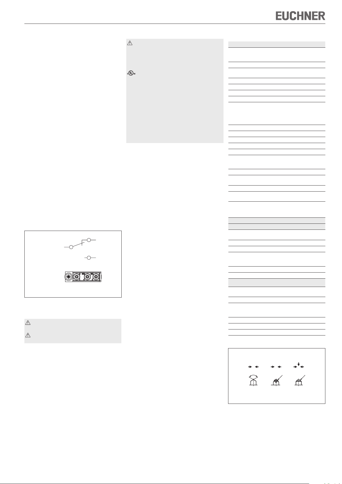
Bezugsfläche
Entlüftungsventil
Bild 4: Maßzeichnung GS...
n
Anzahl
der
Stößel
2 34
4 50
5 58 M20x1,5
Ruhestellung
Schaltpunkt
Leitungseinführung
Stößelabstand 8 mm
l
1
nur an einer Seite
metrisch
Leitungsein-
führung
M16x1,53 42
Nocken
metrisch
Leitungsein-
führung
Nocken
Bezugsfläche
Entlüftungsventil
n
Anzahl
der
Stößel
Ruhestellung
Schaltpunkt
Leitungseinführung
Stößelabstand 8 mm
l
1
2 34
M16x1,53 42
4 50
5 58
6 66
M20x1,5
Bild 5: Maßzeichnung SB...
Bild 6: Maßzeichnung SN...
EUCHNER GmbH + Co. KG Kohlhammerstraße 16 D-70771 Leinfelden-Echterdingen Tel. +49/711/75 97-0 Fax +49/711/75 33 16 www.euchner.de info@euchner.de
Page 3
Operating Instructions Precision Multiple Limit Switches GL, GS, SB, SN 8 mm
D R K
R
4
R
4
120
-5°
1 24
1
4 (NO)
2 (NC)
(C)
Correct use
Precision multiple limit switches are used for positioning and controlling machines and in industrial
installations.
Correct use includes compliance with the relevant
requirements for installation and operation, in
particular
EN 60204-1, Electrical equipment of machines
EN 1050, Safety of machinery. Principles for risk
assessment.
Incorrect use
Precision multiple limit switches with switching element ES 552 und ES 614 (snap-action switching
elements not positively driven) must not be used
in safety circuits.
Function
Precision multiple limit switches possess several
switching elements arranged in a row.
The switching elements are actuated by means of
plungers. Different plunger types and trip dogs are
used depending on the application (operating point
accuracy and approach speed).
The plunger is actuated by trip dogs which are
mounted with an interference fit in trip rails.
The year of manufacture of the switch is indicated
in the production code.
Switching elements / pin assignment
ES 552
ES 614
Top view
on the switching element
Fig. 1: Switching elements and pin assignment
Installation
This unit is to be assembled by authorized
personnel only.
Precision multiple limit switches must not be
used as an end stop.
Fit precision multiple limit switches so that
connection cables and plug connectors are not
damaged by moving parts of the machine
sealing is ensured on cable entry through the
base.
Protection against environmental effects
Safety venting valves are used to equalize the pressure to protect against the pumping action of the
plunger. They must not be sealed with paint.
Mask plunger, plunger guide, safety venting valves
and rating plate during painting work!
Electrical connection
Electrical connection must be performed by
authorized personnel only.
The following applies for switches with UL approval:
For use and applications as per the requirements
of , a class 2 power supply or a class 2
transformer according to UL1310 or UL1585
must be used.
Connection cables for precision multiple limit
switches installed at the place of use must be separated from all moving and permanently installed
cables and un-insulated active elements of other
parts of the system which operate at a voltage of
over 150 V. A constant clearance of 50.8 mm must
be maintained. This does not apply if the moving
cables are equipped with suitable insulation materials which possess an identical or higher dielectric
strength compared to the other relevant parts of
the system.
Open switch cover
Conductor cross-section 0.14 ... 1.0 mm²
For pin assignment see Figure 1
Fit suitable cable gland with captive O-ring
Seal cable carefully. Sealing ring must be matched
to the diameter of the cable
Tighten screws for connections to the switching
element to 0.2 Nm
Close switch cover and tighten cover screws to
0.5 Nm.
Function test
Mechanical function test
Actuate plunger and check the switching func-
tion.
Electrical function test
Check correct function.
Service and inspection
No servicing is required, but regular inspection
of the following is necessary to ensure trouble-free
long-term operation:
correct switching function
secure mounting of components
precise adjustment of trip dog in relation to multiple
limit switch
dirt and wear
sealing of cable entry
loose cable connections.
Exclusion of liability under the following
conditions:
if the unit is not used for its intended purpose
non-compliance with safety regulations
installation and electrical connection not per-
formed by authorized personnel
failure to perform functional checks.
Technical data
Parameter Value
Housing material
Series GL, GS
SB, SN
Plunger material Stainless steel
Degree of protection according to IEC 60529
Mech. operating cycles 30 x 10
Actuation frequency ≤ 200 min
Ambient temperature -5 ... +80 °C
Installation position Any
Approach speed, max.
Plunger Chisel D
Roller R
(slide bearing)
Ball K
Approach speed, min. 0.01 m/min
Actuating force ≥ 15 N
Switching element 1 changeover contact
Switching principle Snap-action switching element
Switching hysteresis max. 0.1 mm
Contact material
ES 552
ES 614
Connection type Screw terminal
Tightening torque
Screw terminal
(Hexagon socket head screw
AF 1.27 mm)
Conductor cross-section 0.14 ... 1.0 mm
Rated impulse
withstand voltage
Rated insulation voltage
with cable entry
with plug connector
Rated data for the switching elements
ES 552
Conv. thermal current I
Utilization category AC-15 230 V / 2 A
Utilization category DC-13 24 V / 2 A
Switching current, min. at
Switching current
Short circuit protection 6 A gG
Mechanical life
ES 614
Conv. thermal current I
Utilization category DC-13 30 V / 1 A
Switching current, min. at
Switching current
Short circuit protection 2 A gG
Mechanical life
Ideal application 1 mA; 5 V ... 0.3 A; 30 V
Preferred approach directions
Sand-cast aluminum, anodized
Die-cast aluminum, anodized
IP 67
20 m/min
50 m/min
8 m/min
Silver
Gold cross cut contacts
0.2 Nm
U
= 2.5 kV
imp
Ui = 250 V
Ui = 50 V
6 A
th
10 mA
DC 24 V
up to 10 x 106 operating cycles
2 A
th
1 mA
DC 5 V
up to 10 x 106 operating cycles
6
-1
2
Figure 2: Plungers and approach directions
Page 4
Operating Instructions Precision Multiple Limit Switches GL, GS, SB, SN 8 mm
8
n
12
14
l
2
22
38
l
3
16
32
55
10
ø5,5
l
1
ø10
30°
ma
x.
38
28
45
ø6
3
4 max.
2
±0,5
30
°
m
ax
.
9,
5
3
4 m
ax
.
4,
5
ø8
40
ø4,5
25
l
1
8
13
n
30
46
3
ø6
2
±0
,5
30
°
ma
x.
12
14
38
45
57
ø6
22
3
4 m
ax
.
16
l
1
ø5,5
72
ø10
10
28
45
30
8
26
n
2
±0
,5
30
°
m
ax
.
9,
5
3
4 m
ax
.
2
±0
,5
4,
5
ø8
40
ø4,5
25
l
1
26
42
8
13
n
ø6
Reference
Reference
surface
surface
Dog
Cable
entry M20x1.5
Cable entry
M20x1.5
Safety venting
valve
n
Number
of
plungers
2 64 50 39
3 80 66 55
4 80 66 55
5 96 82 71
6 96 82 71
8 112 98 87
10 128 114 103
12 144 130 119
Figure 3: Dimension drawing GL...
Safety
venting valve
Plunger spacing 8 mm
l
1
l
2
Free position
Operating point
l
3
Dog
Cable
entry
M20x1.5
Safety venting valve
n
Number
of
plungers
2 48
3 64
4 64
5 80
6 80
8 96
10 112
12 128
14 144
16 160
18 176
20 192
Figure 4: Dimension drawing GS...
Free position
Operating point
Cable entry
M20x1.5
Plunger spacing 8 mm
l
1
Subject to technical modifications, no responsibility is accepted for the accuracy of this information. © EUCHNER GmbH + Co. KG 076050-04-01/08
Reference
surface
Safety
venting
valve
Number
plungers
of
n
2 34
4 50
5 58 M20x1.5
Free position
Operating point
metric
Cable entry
Plunger spacing 8 mm
l
1
Dog
only on one side
Cable entry
M16x1.53 42
Reference
surface
Safety
venting
valve
n
Number
of
plungers
Free position
Operating point
Cable entry
Plunger spacing 8 mm
l
1
Dog
metric
Cable entry
2 34
M16x1.53 42
4 50
5 58
6 66
M20x1.5
Figure 5: Dimension drawing SB...
Figure 6: Dimension drawing SN...
EUCHNER GmbH + Co. KG Kohlhammerstraße 16 D-70771 Leinfelden-Echterdingen Tel. +49/711/75 97-0 Fax +49/711/75 33 16 www.euchner.de info@euchner.de
Page 5

Mode d’emploi pour boîtier multipiste mécanique GL, GS, SB, SN 8 mm
D R K
R
4
R
4
120
-5°
1 24
1
4 (NO)
2 (NC)
(C)
Utilisation conforme
Les boîtiers multipistes mécaniques sont utilisés
pour le positionnement et le contrôle de machines
et d’installations industrielles.
Pour que l’utilisation soit conforme, les instructions
applicables au montage et à la mise en service
doivent être respectées, en particulier
EN 60204-1, Equipement électrique des machi-
nes
EN 1050, Sécurité des machines, appréciation
du risque.
Utilisation non conforme
Les boîtiers multipistes mécaniques dotés de l’élément de commutation ES 552 et ES 614 (éléments
à action brusque sans ouverture forcée) ne doivent
pas être utilisés dans des circuits de sécurité.
Fonction
Les boîtiers multipistes mécaniques possèdent plusieurs éléments de commutation montés en ligne.
Les éléments de commutation sont actionnés
par des poussoirs. Selon la version (précision au
niveau de la répétabilité du point d’action et vitesse
d’actionnement), différents poussoirs et différentes
cames sont utilisés.
L’actionnement des poussoirs est réalisé grâce à
des cames fixées et ajustées par serrage dans des
profils rainurés.
Le code de fabrication indique l’année de fabrication
de l’interrupteur.
Eléments de commutation / affectation
des broches
ES 552
ES 614
Vue de dessus
de l’élément de
commutation
Figure 1 : éléments de commutation et affectation
des broches
Montage
Le montage doit être effectué uniquement par
un personnel agréé.
Les boîtiers multipistes mécaniques ne doivent
pas être utilisés comme butée.
Les boîtiers multipistes mécaniques doivent être
montés de façon à
ce que les câbles de raccordement et les connec-
teurs ne soient pas endommagés par les éléments
mobiles des machines,
ce que l’étanchéité soit garantie au niveau de
l’entrée de câble dans l’embase.
Raccordement électrique
Le raccordement électrique doit être effectué
exclusivement par un personnel habilité.
Pour les interrupteurs avec homologation UL :
Pour que l’utilisation soit conforme aux exigences
de , une alimentation ou un transformateur de
classe 2 doit être utilisé conformément à UL1310
ou UL1585.
Les câbles de raccordement des boîtiers multipistes mécaniques installés sur un site doivent être
séparés des autres câbles électriques, mobiles
ou fixes, et des autres composants non isolés,
d’une distance minimale de 50,8 mm, si ceux-ci
présentent une tension supérieure à 150 V. Ceci
n’est pas nécessaire si les câbles mobiles sont
munis de matériaux isolants adaptés, présentant
une résistance diélectrique égale ou supérieure aux
autres composants importants de l’installation.
Ouvrir le couvercle de l’interrupteur
Section de conducteur 0,14 ... 1,0 mm²
Affectation des broches, voir figure 1.
Monter le presse-étoupe correspondant avec un
joint torique serti.
Sceller soigneusement le câble. Le joint d’étan-
chéité doit correspondre au diamètre de câble.
Serrer les vis de raccordement des éléments de
commutation à 0,2 Nm.
Fermer le couvercle de l’interrupteur et serrer les
vis de couvercle à 0,5 Nm.
Contrôle fonctionnel
Contrôle du fonctionnement mécanique
Actionner le poussoir et contrôler les fonctions
de commutation.
Contrôle du fonctionnement électrique
Veiller au fonctionnement correct.
Entretien et contrôle
Aucun entretien n’est nécessaire. Pour garantir un
fonctionnement durable et parfait, il faut toutefois
vérifier régulièrement les points suivants :
fonction de commutation correcte
bonne fixation des composants
ajustement précis des cames sur les boîtiers
multipistes
dépôts et usure
étanchéité à l’entrée du câble
serrage des connexions
Nous déclinons toute responsabilité
en cas d’utilisation non conforme
en cas de non-respect des consignes de sécurité
si le montage et le raccordement électrique ne
sont pas effectués par du personnel agréé
si les contrôles fonctionnels ne sont pas effectués
Caractéristiques techniques
Paramètre Valeur
Matériau du boîtier
Type GL, GS
SB, SN
Matériau du poussoir Acier, inoxydable
Indice de protection selon la
norme IEC 60529
Manoeuvres mécaniques 30 x 10
Fréquence d’actionnement ≤ 200 min
Température ambiante -5 ... +80 °C
Position de montage Au choix
Vitesse d’actionnement maxi.
Poussoir Toit D
Galet R
(palier de guidage)
Bille K
Vitesse d’actionnement mini. 0,01 m/min
Force d’actionnement ≥ 15 N
Elément de commutation 1 contact inverseur
Principe de commutation Elément à commutation brusque
Hystérèse maxi. 0,1 mm
Matériau des contacts
ES 552
ES 614
Type de raccordement Borne à vis
Couple de serrage
Borne à vis
(vis à six pans creux SW
1,27 mm)
Section de conducteur 0,14 ... 1,0 mm
Tension nominale
d’essai (impulsion)
Tension nominale d’isolement
avec entrée de câble
avec connecteur
Caractéristiques des éléments de commutation
ES 552
Courant thermique conv. Ith6 A
Catégorie d’emploi AC-15 230 V / 2 A
Catégorie d’emploi DC-13 24 V / 2 A
Pouvoir de coupure mini. à
Tension de commutation
Protection contre les courts-
circuits
Durée de vie mécanique jusqu’à 10 x 106 cycles d’action-
ES 614
Courant thermique conv. Ith2 A
Catégorie d’emploi DC-13 30 V / 1 A
Pouvoir de coupure mini. à
Tension de commutation
Protection contre les courts-
circuits
Durée de vie mécanique jusqu’à 10 x 106 cycles d’action-
Domaine d’utilisation idéal 1 mA; 5 V ... 0,3 A; 30 V
Aluminium moulé au sable, anodisé
Aluminium moulé sous pression,
anodisé
IP 67
6
-1
20 m/min
50 m/min
8 m/min
Argent
Contacts en forme de croix, or
0,2 Nm
U
= 2,5 kV
imp
Ui = 250 V
Ui = 50 V
10 mA
DC 24 V
6 A gG
nements
1 mA
DC 5 V
2 A gG
nements
Sens d’attaque privilégiés
2
Protection contre les influences ambiantes
Des échappements, avec un caoutchouc fendu,
servent de compensation de pression contre l’effet
de pompage du poussoir. Ils ne doivent pas être
Figure 2 : poussoirs et sens d’attaque
obstrués avec de la peinture.
En cas de laquage, couvrir les poussoirs, les
barrettes de poussoirs, les échappements et la
plaque signalétique !
Page 6

Mode d’emploi pour boîtier multipiste mécanique GL, GS, SB, SN 8 mm
8
n
12
14
l
2
22
38
l
3
16
32
55
10
ø5,5
l
1
ø10
30°
ma
x.
38
28
45
ø6
3
4 max.
2
±0,5
30
°
m
ax
.
9,
5
3
4 m
ax
.
4,
5
ø8
40
ø4,5
25
l
1
8
13
n
30
46
3
ø6
2
±0
,5
30
°
ma
x.
12
14
38
45
57
ø6
22
3
4 m
ax
.
16
l
1
ø5,5
72
ø10
10
28
45
30
8
26
n
2
±0
,5
30
°
m
ax
.
9,
5
3
4 m
ax
.
2
±0
,5
4,
5
ø8
40
ø4,5
25
l
1
26
42
8
13
n
ø6
Plan de
Plan de
référence
référence
Came
Entrée de câble
M20x1,5
Soupape de
ventilation
Entrée de
câble M20x1,5
Échappement
n
Nombre
de
poussoirs
Pas entre les poussoirs 8 mm
l
1
l
2
2 64 50 39
3 80 66 55
4 80 66 55
5 96 82 71
6 96 82 71
8 112 98 87
10 128 114 103
12 144 130 119
Position de repos
Point d’action
l
3
Came
Entrée
de câble
M20x1,5
Échappement
Entrée de câble
M20x1,5
n
Nombre
de
poussoirs
2 48
3 64
4 64
5 80
6 80
8 96
10 112
12 128
14 144
16 160
18 176
20 192
Position de repos
Point d’action
Pas entre les
poussoirs 8 mm
l
1
Droit de modifications techniques réservé, indications non contractuelles. © EUCHNER GmbH + Co. KG 076050-04-01/08
Figure 3: dimensions GL...
Plan de
référence
Échappement
Figure 4: dimensions GS...
n
Nombre
de
poussoirs
2 34
4 50
5 58 M20x1,5
Position de repos
Point d’action
métrique
Entrée de câble
8 mm
l
1
Pas entre les poussoirs
Came
d’un côté seulement
Entrée de
câble
M16x1,53 42
Plan de
référence
Position de repos
Point d’action
Came
Échappement
métrique
Entrée de câble
n
Nombre
poussoirs
Pas entre les poussoirs
de
8 mm
Entrée de
l
1
câble
2 34
M16x1,53 42
4 50
5 58
6 66
M20x1,5
Figure 5: dimensions SB...
Figure 6: dimensions SN...
EUCHNER GmbH + Co. KG Kohlhammerstraße 16 D-70771 Leinfelden-Echterdingen Tél. : +49/711/75 97-0 Fax : +49/711/75 33 16 www.euchner.de info@euchner.de
Page 7
Istruzioni di impiego finecorsa multipli di precisione GL, GS, SB, SN 8 mm
D R K
R
4
R
4
120
-5°
1 24
1
4 (NO)
2 (NC)
(C)
Impiego conforme alla destinazione d’uso
I finecorsa multipli di precisione vengono utilizzati
per il posizionamento e il comando di macchine e
impianti industriali.
L’impiego conforme alla destinazione d’uso implica
il rispetto delle vigenti norme relative all’installazione
e all’esercizio, in particolare
EN 60204-1, Equipaggiamento elettrico delle
macchine
EN 1050, sicurezza delle macchine, valutazione
del rischio.
Impiego non conforme alla destinazione
d’uso
I finecorsa multipli di precisione con microinterruttore ES 552 e ES 614 (microinterruttore a scatto
rapido senza apertura forzata) non devono essere
impiegati nei circuiti di sicurezza.
Funzionamento
I finecorsa multipli di precisione sono dotati di diversi
microinterruttori disposti in fila.
I microinterruttori vengono azionati tramite pulsanti.
In funzione del tipo di impiego (precisione del punto
di scatto e velocità di azionamento), verranno utilizzati pulsanti e camme diversi.
L'azionamento dei pulsanti nell'applicazione generica avviene mediante camme fissate a filo in profili
scanalati.
L’anno di costruzione del finecorsa può essere
desunto dal codice di produzione.
Microinterruttori/Schema di collegamento
ES 552
ES 614
Vista dall’alto
sul microinterruttore
Figura 1: microinterruttori e commutazioni
Installazione
L’installazione deve essere eseguita esclusivamente da personale specializzato ed autorizzato.
I finecorsa multipli di precisione non devono
essere utilizzati come arresto.
Montare i finecorsa multipli di precisione in modo
che
i cavi di collegamento e i connettori non venga-
no danneggiati da elementi della macchina in
movimento
e sia garantita la tenuta del pressacavo.
Collegamento elettrico
Il collegamento elettrico deve essere eseguito
esclusivamente da personale specializzato ed
autorizzato.
Per i finecorsa con omologazione UL vale:
Per l’introduzione e l’uso conforme ai requisiti
utilizzare alimentazione di tensione classe
2 o trasformatore classe 2 conforme a UL1310
o UL1585.
I cavi di collegamento dei finecorsa multipli di
precisione installati nel punto d’impiego devono
essere separati da cavi mobili e fissi, nonché da
particolari attivi non isolati di altre parti dell’impianto
che lavorano con una tensione di oltre 150 V. È
quindi necessario osservare una distanza costante
di 50,8 mm, a meno che i cavi mobili non siano
dotati di appropriati materiali isolanti che presentino
una tensione d’isolamento equivalente o superiore
rispetto alle altre parti dell’impianto.
Aprire il coperchio dell’interruttore
Sezione del conduttore 0,14 ... 1,0 mm²
Per lo schema di collegamento vedere la Fig. 1.
Montare un idoneo collegamento a pressacavo con
guarnizione O-Ring incorporata
Chiudere il dado a tenuta con estrema cura.
L’anello di tenuta deve essere adatto al diametro
del cavo.
Serrare le viti dei microinterruttori con 0,2 Nm.
Chiudere il coperchio dell’interruttore e serrare le
viti del coperchio con 0,5 Nm.
Verifica delle funzioni
Prova della funzione meccanica
Azionare il pulsante e controllare le commuta-
zioni.
Prova della funzione elettrica
Verificare il corretto funzionamento.
Manutenzione e controllo
Non sono necessari interventi di manutenzione. Per
garantire un funzionamento corretto e durevole si
consiglia comunque di controllare regolarmente
la corretta commutazione
il fissaggio dei singoli componenti
il preciso adattamento delle camme ai finecorsa
multipli
l’eventuale presenza di depositi o segni d’usura
la tenuta dell’ingresso del cavo
l’eventuale allentarsi dei cavi di collegamento.
La responsabilità è esclusa in caso di
impiego non conforme alla destinazione d’uso
mancato rispetto delle istruzioni di sicurezza
montaggio e collegamento elettrico non eseguiti
da personale specializzato ed autorizzato
omissione delle prove funzionali.
Dati tecnici
Parametri Valore
Materiale della custodia
Serie GL, GS
SB, SN
Materiale del pulsante Acciaio, inossidabile
Grado di protezione
sec. IEC 60529
Manovre meccaniche 30 x 10
Frequenza di azionamento ≤ 200 min
Temperatura ambiente -5 ... +80°C
Posizione di installazione qualsiasi
Velocità di azionamento max.
Pulsante A cuneo D
A rotella R
(cuscinetto radente)
Sferico K
Velocità di azionamento min. 0,01 m/min
Forza di azionamento ≥ 15 N
Microinterruttore 1 contatto di commutazione
Principio di commutazione Microinterruttore a scatto rapido
Isteresi di commutazione max. 0,1 mm
Materiale dei contatti
ES 552
ES 614
Tipo di collegamento a vite
Coppia di serraggio a vite
(chiave a brugola da 1,27 mm)
Sezione conduttori 0,14 ... 1,0 mm
Rigidità dielettrica
impulsiva di taratura
Tensione di isolamento
con ingresso del cavo
con connettore
Dati dei microinterruttori
ES 552
Corrente continua termica
standard I
Categoria di impiego AC-15 230 V/2 A
Categoria di impiego DC-13 24 V/2 A
Corrente di commutazione
min. a
Tensione nominale di impiego
Protezione contro cortocircuiti 6 A gG
Durata meccanica sino a 10 x 106 cicli di manovra
ES 614
Corrente continua termica
standard I
Categoria di impiego DC-13 30 V/1 A
Corrente di commutazione
min. a
Tensione nominale di impiego
Protezione contro cortocircuiti 2 A gG
Durata meccanica sino a 10 x 106 cicli di manovra
Campo d’impiego ideale 1 mA; 5 V ... 0,3 A 30 V
th
th
Direzioni di azionamento
Alluminio fuso in sabbia anodizzato
Alluminio pressofuso anodizzato
IP 67
6
-1
20 m/min
50 m/min
8 m/min
argento
oro (contatti con taglio a croce)
0,2 Nm
2
U
= 2,5 kV
imp
Ui = 250 V
Ui = 50 V
6 A
10 mA
DC 24 V
2 A
1 mA
DC 5 V
Protezione contro gli agenti ambientali
Le valvole di sfiato consentono di compensare la
pressione contro l’effetto pompante dei pulsanti.
Non devono essere otturate da vernice.
Durante i lavori di verniciatura, coprire i pulsanti
Fig. 2: Pulsanti e direzioni di azionamento
e le relative guide, le valvole di sfiato e l’etichetta
d’identificazione.
Page 8

Istruzioni di impiego finecorsa multipli di precisione GL, GS, SB, SN 8 mm
8
n
12
14
l
2
22
38
l
3
16
32
55
10
ø5,5
l
1
ø10
30°
ma
x.
38
28
45
ø6
3
4 max.
2
±0,5
30
°
m
ax
.
9,
5
3
4 m
ax
.
4,
5
ø8
40
ø4,5
25
l
1
8
13
n
30
46
3
ø6
2
±0
,5
30
°
ma
x.
12
14
38
45
57
ø6
22
3
4 m
ax
.
16
l
1
ø5,5
72
ø10
10
28
45
30
8
26
n
2
±0
,5
30
°
m
ax
.
9,
5
3
4 m
ax
.
2
±0
,5
4,
5
ø8
40
ø4,5
25
l
1
26
42
8
13
n
ø6
Superficie di
Superficie di
riferimento
riferimento
Camma
Pressacavo
M20x1,5
Valvola di sfiato
Foro per
cavo M20x1,5
Posizione di riposo
Punto di scatto
Valvola
di sfiato
n
Numero
pulsanti
l
1
Passo 8 mm
l
2
2 64 50 39
3 80 66 55
4 80 66 55
5 96 82 71
6 96 82 71
8 112 98 87
10 128 114 103
12 144 130 119
Camma
Foro per
cavo
M20x1,5
Posizione di riposo
Punto di scatto
Valvola di sfiato
Pressacavo
M20x1,5
n
l
3
Numero
pulsanti
Passo 8 mm
l
1
2 48
3 64
4 64
5 80
6 80
Con riserva di modifiche tecniche, tutti i dati esenti da garanzia. © EUCHNER GmbH + Co. KG 076050-04-01/08
8 96
10 112
12 128
14 144
16 160
18 176
20 192
Fig. 3: dimensioni GL...
Valvola di sfiato
Superficie di
riferimento
n
Numero
pulsanti
2 34
4 50
5 58 M20x1,5
Posizione di riposo
Punto di scatto
metrico
Pressacavo
Passo 8 mm
l
1
solo su un lato
Pressacavo
M16x1,53 42
Camma
Fig. 4: dimensioni GS...
Superficie di
riferimento
Valvola di sfiato
n
Numero
pulsanti
Posizione di riposo
Punto di scatto
Pressacavo
Passo 8 mm
l
1
2 34
4 50
5 58
6 66
Camma
metrico
Pressacavo
M16x1,53 42
M20x1,5
Fig. 5: dimensioni SB...
Fig. 6: dimensioni SN...
EUCHNER GmbH + Co. KG Kohlhammerstraße 16 D-70771 Leinfelden-Echterdingen Tel. +49/711/75 97-0 Fax +49/711/75 33 16 www.euchner.de info@euchner.de
 Loading...