

Page 1
Betriebsanleitung Sicherheitsschalter SGP-TW...
(Twin)
Bestimmungsgemäßer Gebrauch
Sicherheitsschalter der Baureihe SGP-TW sind Verriegelungseinrichtungen ohne Zuhaltung.
In Verbindung mit einer trennenden Schutzeinrichtung verhindert dieses Sicherheitsbauteil, dass
gefährliche Maschinenbewegungen ausgeführt
werden, solange die Schutzeinrichtung geöffnet ist.
Wenn die Schutzeinrichtung während der gefährlichen Maschinenfunktion geöffnet wird, wird ein HaltBefehl ausgelöst.
Die Sicherheitsschalter der Typenreihe SGP-TW entsprechen den Vorschriften EN 60947-5-1 (inkl. Anhang K) und erfüllen die Anforderungen der Berufsgenossenschaften für Maschinen, Anlagen und Personenschutz.
Vor dem Einsatz von Sicherheitsschaltern ist eine
Risikobeurteilung an der Maschine durchzuführen
nach
EN ISO 13849-1, Sicherheitsbezogene Teile von
Steuerungen
EN ISO 14121, Sicherheit von Maschinen, Risikobeurteilung
IEC 62061, Sicherheit von Maschinen - Funktionale Sicherheit sicherheitsbezogener elektrischer,
elektronischer und programmierbarer elektronischer Steuerungssysteme.
Zum bestimmungsgemäßen Gebrauch gehört das
Einhalten der einschlägigen Anforderungen für den
Einbau und Betrieb, insbesondere
EN ISO 13849-1, Sicherheitsbezogene Teile von
Steuerungen
EN 1088, Verriegelungseinrichtungen in Verbindung mit trennenden Schutzeinrichtungen
EN 60204-1, Elektrische Ausrüstung von Maschinen.
Wichtig:
Der Anwender trägt die Verantwortung für die
sichere Einbindung des Geräts in ein sicheres
Gesamtsystem. Dazu muss das Gesamtsystem
z. B. nach EN ISO 13849-2 validiert werden.
Wird zur Validierung das vereinfachte Verfahren
nach Abschnitt 6.3 EN ISO 13849-1:2008 benutzt, reduziert sich möglicherweise der Performance Level (PL), wenn mehrere Geräte
hintereinander geschaltet werden.
Liegt dem Produkt ein Datenblatt bei, gelten die
Angaben des Datenblatts, falls diese von der
Betriebsanleitung abweichen.
Sicherheitshinweise
Sicherheitsschalter erfüllen eine PersonenschutzFunktion. Unsachgemäßer Einbau oder Manipulationen können zu schweren Verletzungen von Personen führen.
Sicherheitsbauteile dürfen nicht umgangen (Kontakte überbrückt), weggedreht, entfernt oder auf
andere Weise unwirksam gemacht werden.
Beachten Sie hierzu insbesondere die Maßnahmen
zur Verringerung der Umgehungsmöglichkeiten
nach EN 1088:1995.A2:2008, Abschn. 5.7.
Der Schaltvorgang darf nur durch speziell dafür
vorgesehene Betätiger ausgelöst werden, die
unlösbar mit der Schutzeinrichtung verbunden sind.
Montage, elektrischer Anschluss und Inbetriebnahme ausschließlich durch autorisiertes Fachpersonal.
Funktion
Sicherheitsschalter der Baureihe SGP-TW...
sitzen zwei Betätigerköpfe. Sie ermöglichen das
gleichzeitige Überwachen von zwei beweglichen
Schutzeinrichtungen.
Der Sicherheitsschalter meldet, dass die Schutzeinrichtung geschlossen ist.
Durch den Schalter erfolgt keine Zuhaltung!
(Twin)
be-
Schließen
Durch Einführen der beiden Betätiger werden die
Sicherheitskontakte geschlossen.
Öffnen
Durch Herausziehen eines der beiden Betätiger werden die Sicherheitskontakte zwangsweise geöffnet.
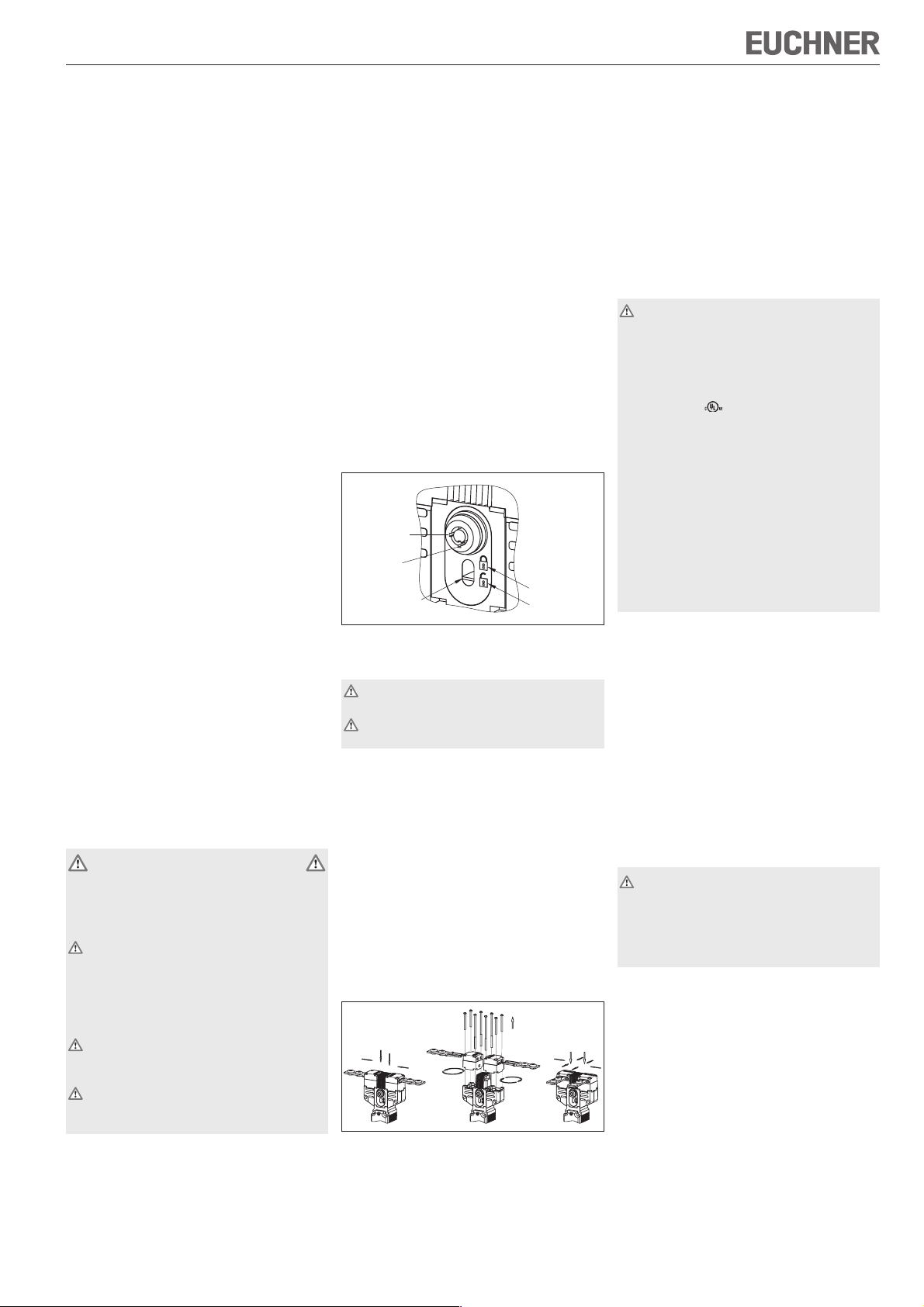
Schlossfunktion (optional)
Verfügt der Schalter über eine Schlossfunktion,
kann der Sicherheitskreis des Antriebs geöffnet und
in dieser Stellung gehalten werden (siehe Bild 1).
Damit wird ein unbeabsichtigtes Anlaufen der Anlage verhindert.
Schlossfunktion betätigen
1. Schlüssel in die Schlossöffnung stecken
2. Schlüssel von Pos.1 (Normalbetrieb) auf Pos.2
(Sperrbetrieb) drehen
3. Schlüssel abziehen
4. Nach Gebrauch wieder zurückstellen.
Anzeige
Die Stellung der Schlossfunktion wird im Sichtfenster angezeigt.
Pos. 1
(Normalbetrieb)
Pos. 2
(Sperrbetrieb)
Markierung
Sicherheitskreis
geschlossen
Sicherheitskreis
geöffnet
Bild 1: Schlossfunktion und Anzeige
Montage
Sicherheitsschalter und Betätiger dürfen nicht
als Anschlag verwendet werden.
Nur in zusammengebautem Zustand befestigen!
Sicherheitsschalter so anbauen, dass
er für Bedienpersonal bei geöffneter Schutzeinrichtung schwer zugänglich ist.
Wartung und Austausch möglich ist.
Betätiger in Betätigungskopf einführen.
Sicherheitsschalter formschlüssig anbauen.
Für sicherheitstechnische Anwendungen (fixierte
Position) Schalter mit Schrauben M5x30 anbauen.
Betätiger dauerhaft und unlösbar mit der Schutzeinrichtung verbinden, z.B. durch die beiliegenden Einwegschrauben, nieten oder schweißen.
Zusätzlichen Anschlag für beweglichen Teil der
Schutzeinrichtung anbringen.
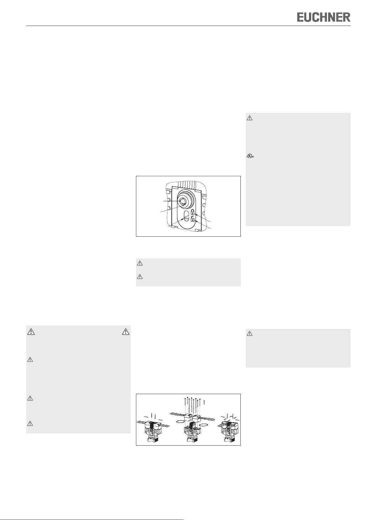
Umstellen der Betätigungsrichtung
Bild 2: Umstellen der Betätigungsrichtung
Schrauben am Betätigungskopf lösen.
Gewünschte Richtung einstellen.
Richtige Anordnung der Schrauben (siehe Bild 2).
Schrauben mit 0,6 Nm anziehen.
Nicht benutzte Betätigungsschlitze mit beiliegenden Schlitzabdeckungen verschließen.
Schutz vor Umgebungseinflüssen
Voraussetzung für eine dauerhafte und einwandfreie Sicherheitsfunktion ist der Schutz des Betätigungskopfes vor eindringenden Fremdkörpern wie
Spänen, Sand, Strahlmitteln usw.
Nicht benutzten Betätigungsschlitz mit Schlitzabdeckung verschließen.
Bei Lackierarbeiten den Betätigungsschlitz, den Betätiger und das Typenschild abdecken!
Zur Reinigung der Schalter nur lösungsmittelfreie
Reinigungsmittel verwenden!
Elektrischer Anschluss
Bei der Auswahl von Isolationsmaterial bzw.
Anschlusslitzen, auf die Übertemperatur im
Gehäuse (abhängig von den Betriebsbedingun-
gen) achten!
Für SGP-TW mit Steckverbinder gilt:
Für den Einsatz und die Verwendung gemäß den An-
forderungen von muss eine class 2 Spannungsversorgung oder ein class 2 Transformator nach
UL1310 oder UL1585 verwendet werden.
Am Einsatzort installierte Anschlussleitungen von
Sicherheitsschaltern müssen räumlich von beweglichen und fest installierten Leitungen und nicht
isolierten aktiven Teilen anderer Anlagenteile, die
mit einer Spannung von über 150 V arbeiten, so
getrennt werden, dass ein ständiger Abstand von
50,8 mm eingehalten wird. Es sei denn, die beweglichen Leitungen sind mit geeigneten Isoliermaterialien versehen, die eine gleiche oder höhere Spannungsfestigkeit gegenüber den anderen
relevanten Anlagenteilen besitzen.
Ausführung SGP-TW-1... (Leitungseinführung
M20x1,5/NPT ½'' siehe Typenschild)
Gewünschte Einführöffnung ausbrechen.
Kabelverschraubung mit entsprechender Schutzart montieren.
Leiterquerschnitt bis max. 1,5 mm².
Kontaktbelegung siehe Bild 3.
Klemmschrauben mit 0,6 Nm anziehen.
Auf Dichtheit der Leitungseinführung achten.
Schalterdeckel schließen und verschrauben.
Ausführung SGP-TW-2... (Steckverbinder SR6/
SR11 siehe Typenschild)
Kontaktbelegung siehe Bild 3.
Funktionskontrolle
Warnung! Tödliche Verletzung durch Fehler bei
der Installation und Funktionskontrolle.
Stellen Sie vor der Funktionskontrolle sicher,
dass sich keine Personen im Gefahrenbereich
befinden. Beachten Sie die geltenden Vorschrif-
ten zur Unfallverhütung.
Nach der Installation und jedem Fehler muss eine
vollständige Kontrolle der Sicherheitsfunktion durchgeführt werden. Gehen Sie dabei folgendermaßen
vor:
Mechanische Funktionsprüfung
Der Betätiger muss sich leicht in den Betätigungskopf einführen lassen. Zur Überprüfung Schutzeinrichtung mehrmals schließen.
Elektrische Funktionsprüfung
1. Betriebsspannung einschalten.
2. Alle Schutzeinrichtungen schließen.
Die Maschine darf nicht selbständig anlaufen.
3. Betrieb in der Steuerung freigeben.
4. Schutzeinrichtung öffnen.
Page 2
Betriebsanleitung Sicherheitsschalter SGP-TW...
34
42
22
12
12
22
42
34
22
42
34
Die Maschine muss abschalten und darf sich nicht
starten lassen, solange die Schutzeinrichtung
geöffnet ist.
Wiederholen Sie die Schritte 2 - 4 für jede Schutzeinrichtung einzeln.
Kontrolle und Wartung
Bei Beschädigung oder Verschleiß muss der
gesamte Schalter mit Betätiger ausgetauscht
werden.
Der Austausch von Einzelteilen oder Baugruppen ist unzulässig!
Wartungsarbeiten sind nicht erforderlich. Um eine
einwandfreie und dauerhafte Funktion zu gewährleisten, sind regelmäßige Kontrollen erforderlich
auf
einwandfreie Schaltfunktion
sichere Befestigung der Bauteile
Ablagerungen und Verschleiß
Dichtheit der Kabeleinführung
gelockerte Leitungsanschlüsse.
Sicherheitsschalter müssen nach 1 Million Schaltspielen komplett ausgetauscht werden.
Hinweis: Das Baujahr ist in der unteren, rechten
Ecke des Typenschilds ersichtlich.
Haftungsausschluss bei
nicht bestimmungsgemäßem Gebrauch
Nichteinhalten der Sicherheitshinweise
Anbau und elektrischem Anschluss durch nicht
autorisiertes Fachpersonal.
nicht durchgeführten Funktionskontrollen.
Konformitätserklärung
Siehe Anhang 1 der Betriebsanleitung.
Technische Daten
Parameter Wert
Gehäusewerkstoff Glasfaserverstärkter Thermoplast
Schutzart nach IEC 60529
SGP-TW-1... IP67
SGP-TW-2... IP65
Mech. Lebensdauer 1x10⁶ Schaltspiele
Umgebungstemperatur -20...+80°C
Verschmutzungsgrad
(extern, nach EN 60947-1)
Einbaulage beliebig
Anfahrgeschwindigkeit max. 20 m/min
Betätigungskraft 25 N
Betätigungshäufigkeit max. 6700 / h
Auszugskraft 25 N
Rückhaltekraft 10 N
Schaltprinzip Schleichschaltglied
Kontaktwerkstoff Silberlegierung hauchvergoldet
Anschlussart
SGP-TW-1... Schraubanschluss
SGP-TW-2...SR6 Steckverbinder SR6, 6-polig+PE
SGP-TW-2...SR11 Steckverbinder SR11, 11-polig+PE
Leiterquerschnitt (starr/flexibel)
SGP-TW-1... 0,34...1,5 mm²
SGP-TW-2...SR6 0,5...1,5 mm²
SGP-TW-2...SR11 0,5 mm²
Betriebsspannung für L060 12 - 60 V
optionale LED-Anzeige L110 110 V
(nur SGP-TW...528H
/SGP-TW...538H)
Schaltspannung min.
bei 10 mA
Schaltstrom min. bei 24 V 1 mA
Kurzschlussschutz (Steuersicherung) nach IEC 60269-1
Konv. thermischer Strom Ith4 A
Gebrauchskategorie SGP-TW-1.../
nach EN 60947-5-1 SGP-TW-2...SR6 SGP-TW-2...SR11
AC-15 4 A 230 V 4 A 50 V
DC-13 4 A 24 V 4 A 24 V
Bemessungsstoß-
spannungsfestigkeit
Bemessungsisolationsspannung
Zuverlässigkeitswerte nach EN ISO 13849-1
B
10d
3 (Industrie)
L220 230 V
12 V
4 A gG
U
= 2,5 kV
imp
Ui = 250 V
6
2 x 10
(Twin)
Technische Änderungen vorbehalten, alle Angaben ohne Gewähr. © EUCHNER GmbH + Co. KG 100872-04-05/10 (Originalbetriebsanleitung)
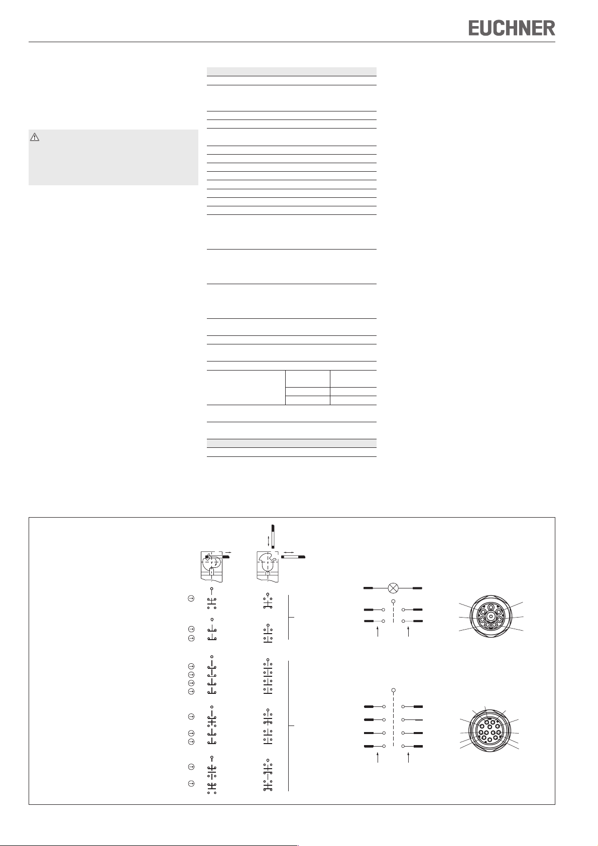
Tür
geschlossen
Ausführung Schaltglieder
22
SGP-TW-.-528H... 1 Öffner + 1 Schließer
SGP-TW-.-538H... 2 Öffner
SGP-TW-.-2121H... 4 Öffner
SGP-TW-.-2131H... 3 Öffner + 1 Schließer
SGP-TW-.-3131H... 2 Öffner + 2 Schließer
Bild 3: Schaltelemente und Schaltfunktionen
EUCHNER GmbH + Co. KG Kohlhammerstraße 16 D-70771 Leinfelden-Echterdingen Tel. +49/711/75 97-0 Fax +49/711/75 33 16 www.euchner.de info@euchner.de
21
14
13
22
21
12
11
42
41
34
33
22
21
12
11
42
41
34
33
22
21
12
11
42
41
34
33
22
21
14
13
21 22
11 12
33 34
21 22
41 42
11 12
33 34
21 22
Tür
offen
1413
2221
4241
1211
3433
2221
4241
1413
Steckverbinder
SR6
Steckverbinder
SR11
Kontaktbelegung
mit Steckverbinder
(freiverdrahtbare LED-Anzeige, optional)
5
1
3
Schaltelemente
7
5
3
1
Ordnungsziffer
Schaltelemente
2.
1.
Ordnungsziffer
der
3. 3.
2.
1. 1.
der
6
2.
2
1.
4
4.4.
8
6
2.
4
2
Steckerbild
(Ansicht Steckseite
Sicherheits-
schalter)
2
3
4
10
4
3
2
9
1
1
6
5
5
6
7
11
8
Page 3
Betriebsanleitung Sicherheitsschalter SGP-TW...
(Twin)
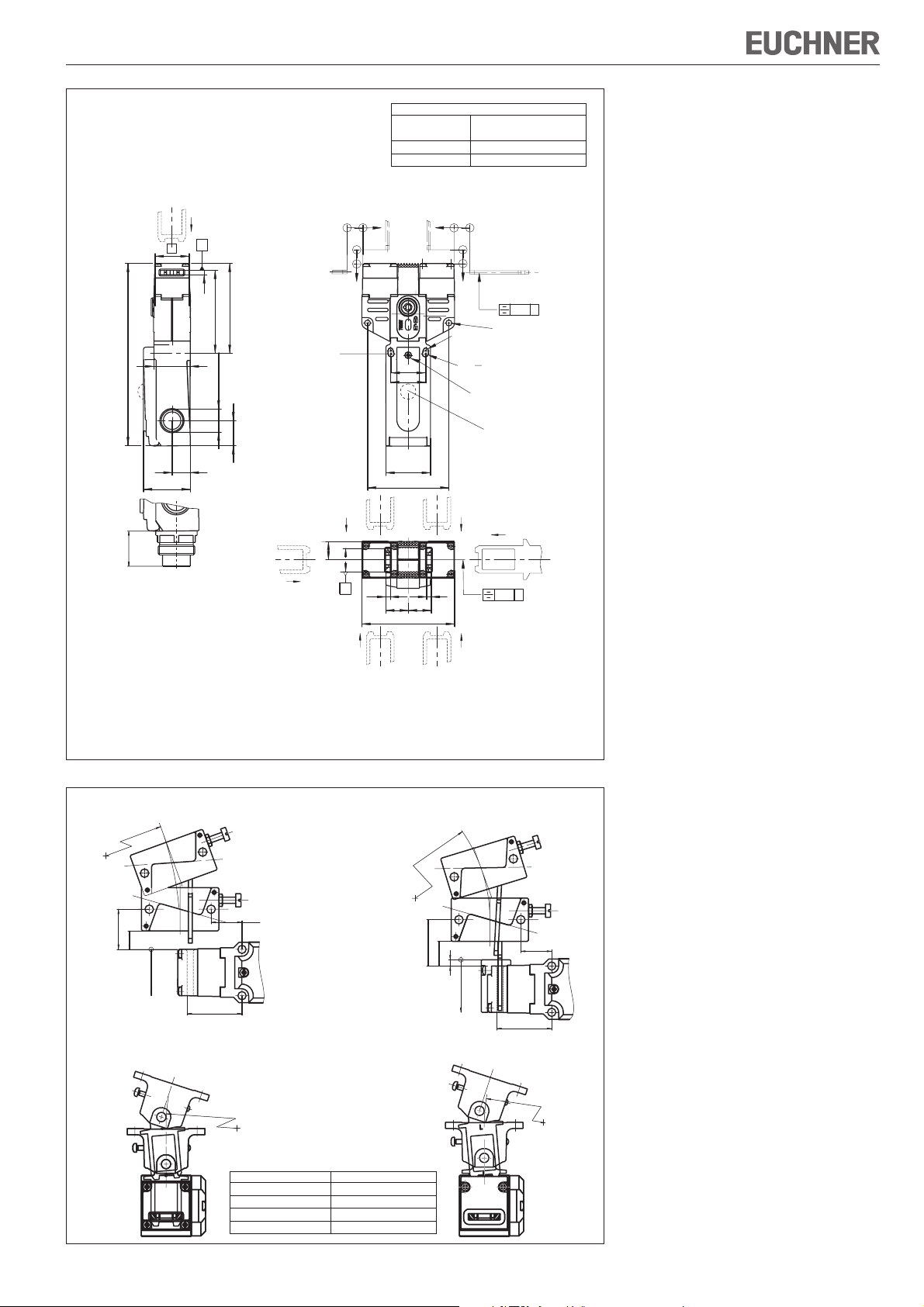
160
Erforderlicher Mindestweg + zul. Nachlauf [mm]
S
Anfahrrichtung
Betätiger
Standard
horizontal (h) 24,5 + 5
vertical (v) 24,5 + 5
Betätiger separat bestellen
30
31
<40>
72
Eintauchtiefe
h
v
Ø4,1
Ø5,1
M=0,6Nm
0,3 A
Ø
5,2
fixierte Positionierung
für Sicherheitsanwendungen
(Schraube M5)
optionale
LED-Anzeige
(nur SGP-TW...528H/
SGP-TW...538H)
h
B
30
4
<79>
<73>
32
x1,5 (3x)
M 20
22
16
41,2
28
Eintauch-
tiefe
16
v
Bild 4: Maßzeichnung SGP-TW...
Radiusbetätiger S-OU-SN
200
R >
26
12
24,5 +5
35,5
Radiusbetätiger S-LR-SN
B
44
20 20
82
Radiusbetätiger S-OU-LN
R > 200
20
30
16
4
Radiusbetätiger S-LR-LN
0,3 B
für Einführtrichter
20
28,5 +5
35,5
für Einführtrichter
Bild 5: Minimale Türradien
R>200
R>200
Betätiger-Typ Türradius min. [mm]
Betaetiger-S-G... 300
Betaetiger-S-W... 300
RADIUSBETAETIGER-S-OU... 200
RADIUSBETAETIGER-S-LR... 200
Page 4
Operating Instructions Safety Switch SGP-TW...
(Twin)
Correct Use
Safety switches series SGP-TW are interlocking
devices without guard locking.
In combination with a separating safety guard, this
safety component prevents dangerous machine
movements from being performed for as long as the
safety guard is open. A stop command is triggered if
the safety guard is opened during the dangerous
machine function.
The safety switches series SGP-TW comply with the
regulations of EN 60947-5-1 (incl. Annex K) and
comply with the requirements of the employers’ liability
insurance associations for machines, installations and
personnel protection.
Before safety switches are used, a risk assessment
must be performed on the machine in accordance
with
EN ISO 13849-1, Safety of machinery. Safety related
parts of control systems. General principles for
design
EN ISO 14121, Safety of machinery. Risk
assessment. Principles
IEC 62061, Safety of machinery – Functional safety
of safety-related electrical, electronic and
programmable electronic control systems.
Correct use includes compliance with the relevant
requirements for installation and operation, particularly
EN ISO 13849-1, Safety of machinery. Safety related
parts of control systems. General principles for
design
EN 1088, Safety of machinery. Interlocking devices
associated with guards. Principles for design and
selection
EN 60204-1, electrical equipment of machines
Important:
The user is responsible for safe integration of the
device in a safe overall system. For this purpose
the overall system must be validated, e.g. in
accordance with EN ISO 13849-2.
If the simplified method according to section 6.3
EN ISO 13849-1:2008 is used for validation, the
Performance Level (PL) may be reduced if several
devices are connected one after the other.
If a product data sheet is included with the product,
the information on the data sheet applies in case of
discrepancies with the operating instructions.
Safety Precautions
Safety switches fulfill a personal protection function.
Incorrect installation or tampering can lead to severe
injuries to personnel.
Safety components must not be bypassed
(bridging of contacts), turned away, removed or
otherwise rendered ineffective.
On this topic pay attention in particular to the
measures for reducing the possibility of bypassing
according to EN 1088:1995.A2:2008, sec. 5.7.
The switching operation may only be triggered
by actuators specially provided for this purpose
which are permanently connected to the
protective guard.
Mounting, electrical connection and setup only
by authorized personnel.
Function
Safety switches series SGP-TW..
actuator heads. They permit the simultaneous
monitoring of two movable safety guards.
The safety switch signals that the safety guard is
closed.
The switch does not perform guard locking!
(Twin)
have two
Closing
The safety contacts are closed by inserting the two
actuators.
Opening
The safety contacts are positively opened by
withdrawing one of the two actuators.
Lock Function (optional)
If the switch has a lock function, the drive’s safety
circuit can be opened and retained in this position
(see Figure 1). This prevents accidental starting of
the system.
Actuating the lock function
1. Insert key in the key opening
2. Rotate key from pos.1 (normal operation) to pos.2
(locked)
3. Remove key
4. Return to original position after use.
Indication
The lock function setting is indicated in the window.
Pos. 1
(normal
operation)
Pos. 2
(locked)
Marking
Safety circuit
closed
Safety circuit
open
Figure 1: Lock function and indication
Installation
Safety switches and actuators must not be used
as an end stop.
Mount the safety switch only in assembled
condition!
Assemble the safety switch so that
access to the switch is difficult for operating
personnel when the safety guard is open.
maintenance and replacement are possible.
Insert the actuator in the actuating head.
Mount the safety switch positively.
For safety-related applications (fixed position),
mount switch with M5x30 screws.
Permanently connect the actuator to the safety
guard so that it cannot be detached, e.g. using
the enclosed non-removable screws, rivets or
welding.
Fit an additional stop for the movable part of the
safety guard.
Changing the Actuating Direction
Figure 2: Changing the actuating direction
Remove the screws from the actuating head.
Set the required direction.
Correct arrangement of the screws (see figure 2).
Tighten the screws with a torque of 0.6 Nm.
Cover the unused actuating slots with the enclosed
slot covers.
Protection Against Environmental Influences
A lasting and correct safety function requires that the
actuating head must be protected against the
penetration of foreign bodies such as swarf, sand,
blasting shot, etc.
Cover the unused actuating slot with the slot cover.
Cover the actuating slot, the actuator and the rating
plate during painting work!
Only use solvent-free cleaning agents to clean the
switch!
Electrical Connection
When choosing the insulation material and wire
for the connections, pay attention to the overtemperature in the housing (depending on the
operating conditions)!
For SGP-TW with plug connector:
For use and applications as per the requirements of
, a class 2 power supply or a class 2 transformer
according to UL1310 or UL1585 must be used.
Connection cables for safety switches installed at
the place of use must be separated from all moving
and permanently installed cables and un-insulated
active elements of other parts of the system which
operate at a voltage of over 150 V. A constant
clearance of 50.8 mm must be maintained. This does
not apply if the moving cables are equipped with
suitable insulation materials which possess an
identical or higher dielectric strength compared to
the other relevant parts of the system.
Version SGP-TW-1...
(cable entry M20x1.5/NPT ½“, see rating plate)
Break out the required entry opening.
Fit the cable gland with the appropriate degree of
protection.
The maximum conductor cross-section is 1.5 mm².
For pin assignment see Figure 3.
Tighten the screws with a torque of 0.6 Nm.
Check that the cable entry is sealed.
Close the cover and screw in position.
Version SGP-TW-2...
(plug connector SR6/SR11, see rating plate)
For pin assignment see Figure 3.
Functional Check
Warning! Danger of fatal injury as a result of faults
in installation and functional check.
Before carrying out the functional check, make
sure that there are no persons in the danger
area. Observe the valid accident prevention
regulations.
After installation and any fault, the safety function must
be fully checked. Proceed as follows:
Mechanical function test
The actuator must slide easily into the actuating head.
Close the safety guard several times to check the
function.
Electrical function test
1. Switch on operating voltage.
2. Close all safety guards.
The machine must not start automatically.
3. Enable operation in the control system.
4. Open the safety guard.
The machine must switch off and it must not be
possible to start it as long as the safety guard is
open.
Repeat steps 2 - 4 for each safety guard.
Page 5

Operating Instructions Safety Switch SGP-TW...
34
42
22
12
12
22
42
34
22
42
34
(Twin)
Inspection and Service
If damage or wear is found, the complete switch
and actuator assembly must be replaced.
Replacement of individual parts or assemblies
is not permitted!
No servicing is required, but regular inspection of
the following is necessary to ensure trouble-free longterm operation:
correct switching function
secure mounting of components
dirt and wear
sealing of cable entry
loose cable connections.
Safety switches must be completely replaced after 1
million operating cycles.
Note: The year of manufacture can be seen in the
bottom, right corner of the rating plate.
Exclusion of Liability under the Following
Conditions:
if the unit is not used for its intended purpose
non-compliance with safety regulations
installation and electrical connection not performed
by authorized personnel.
failure to perform functional checks.
Declaration of Conformity
See Annex 1 of the operating instructions.
Technical Data
Parameters Value
Housing material Reinforced thermoplastic
Degree of protection according to IEC 60529
SGP-TW-1... IP67
SGP-TW-2... IP65
Mech. Mechanical life 1x10⁶ operating cycles
Ambient temperature -20 ... +80°C
Degree of contamination
(external, according ?to 3 (industrial)
EN 60947-1)
Installation position Any
Approach speed, max. 20 m/min
Actuating force 25 N
Actuation frequency, max. 6700 / h
Extraction force 25 N
Retention force 10 N
Switching principle Slow-action switching contact
Contact material Silver alloy, gold flashed
Connection type
SGP-TW-1... Screw terminal
SGP-TW-2...SR6 Plug connector SR6, 6-pin+PE
SGP-TW-2...SR11 Plug connector SR11, 11-pin+PE
Conductor cross-section (rigid/flexible)
SGP-TW-1... 0.34...1.5 mm²
SGP-TW-2...SR6 0.5...1.5 mm²
SGP-TW-2...SR11 0.5 mm²
Operating voltage for
optional LED indicator
(only SGP-TW...528H/
SGP-TW...538H)
Switching voltage min.
at 10 mA
Switching current, min.,
at 24 V
Short circuit protection
(control circuit fuse) 4 A gG
according to IEC 60269-1
Conv. thermal current I
Utilization category SGP-TW-1.../
according to EN 60947-5-1 SGP-TW-2...SR6 SGP-TW-2...SR11
AC-15 4 A 230 V 4 A 50 V
DC-13 4 A 24 V 4 A 24 V
Rated impulse
withstand voltage
Rated insulation voltage Ui = 250 V
Reliability figures according to EN ISO 13849-1
B
10d
L060 12 - 60 V
L110 110 V
L220 230 V
12 V
1 mA
4 A
th
U
= 2.5 kV
imp
2 x 10
6
Door closed Door open
Contact assignment with
plug connector
Version Switching contacts
22
SGP-TW-.-528H... 1 NC contact +
SGP-TW-.-538H... 2 NC contacts
SGP-TW-.-2121H... 4 NC contacts
SGP-TW-.-2131H... 3 NC contacts +
SGP-TW-.-3131H... 2 NC contacts +
Figure 3: Switching elements and switching functions
EUCHNER GmbH + Co. KG Kohlhammerstraße 16 D-70771 Leinfelden-Echterdingen Tel. +49/711/75 97-0 Fax +49/711/75 33 16 www.euchner.de info@euchner.de
1 NO contact
1 NO contact
2 NO contacts
21
14
13
22
21
12
11
42
41
34
33
22
21
12
11
42
41
34
33
22
21
12
11
42
41
34
33
22
21
14
13
21 22
11 12
33 34
21 22
41 42
11 12
33 34
21 22
1413
2221
4241
1211
3433
2221
4241
1413
(LED indicator with full wiring options, optional)
5
2.
Plug connector
SR6
1
1.
3
Ordinal numbers of
switching elements
7
3. 3.
Plug connector
SR11
5
2.
3
1. 1.
1
Ordinal numbers of
switching elements
6
2.
2
1.
4
4.4.
8
6
2.
4
2
Connector
illustration
(view of safety switch
connection side)
2
3
4
10
4
3
2
9
1
1
6
5
5
6
7
11
8
Subject to technical modifications; no responsibility is accepted for the accuracy of this information. © EUCHNER GmbH + Co. KG 100872-04-05/10 (translation of the original operating instructions)
Page 6

Operating Instructions Safety Switch SGP-TW...
(Twin)
160
Necessary minimum travel + permissible overtravel [mm]
S
Approach direction
Actuator
Standard
Horizontal (h) 24,5 + 5
Vertical (v) 24,5 + 5
Order actuator separately
30
31
<40>
72
Insertion depth
h
v
Ø
Ø4,1
Ø5,1
M=0,6Nm
0,3 A
5,2
Fixed positioning for safetyrelated applications (screw M5)
Optional LED indicator
(only SGP-TW...528H/
SGP-TW...538H)
h
B
30
4
<79>
<73>
32
x1,5 (3x)
M 20
22
16
41,2
28
Insertion
16
depth
v
Figure 4: Dimension drawing SGP-TW...
Hinged actuator S-OU-SN
200
R >
26
12
24,5 +5
35,5
Hinged actuator S-LR-SN
B
44
20 20
82
Hinged actuator S-OU-LN for
R > 200
20
30
16
4
Hinged actuator S-LR-LN for
0,3 B
insertion funnel
20
28,5 +5
35,5
insertion funnel
Figure 5: Min. door radii
R>200
R>200
Actuator type Door radius min. [mm]
Actuator S-G... 300
Actuator S-W... 300
HINGED ACTUATOR S-OU... 200
HINGED ACTUATOR S-LR... 200
Page 7

Mode d’emploi pour les interrupteurs de sécurité SGP-TW...
(Twin)
Utilisation conforme
Les interrupteurs de sécurité de la série SGP-TW sont
des dispositifs de verrouillage sans système
d’interverrouillage.
Utilisé avec un protecteur, ce composant de sécurité
interdit tout mouvement dangereux de la machine tant
que le protecteur est ouvert. Un ordre d’arrêt est
émis en cas d’ouverture du protecteur pendant le
fonctionnement dangereux de la machine.
Les interrupteurs de sécurité de la série SGP-TW
répondent aux prescriptions EN 60947-5-1 (incl.
Annexe K) et satisfont aux exigences des organismes
professionnels concernant les machines, les
installations et la protection des personnes.
Avant d’utiliser des interrupteurs de sécurité, il est
nécessaire d’effectuer une analyse d’appréciation du
risque sur la machine selon
EN ISO 13849-1, Parties des systèmes de
commande relatives à la sécurité ;
EN ISO 14121, Sécurité des machines, appréciation
du risque
IEC 62061, Sécurité des machines – Sécurité
fonctionnelle des systèmes de commande
électriques, électroniques et électroniques
programmables relatifs à la sécurité.
Pour que l’utilisation soit conforme, les instructions
applicables au montage et à la mise en service doivent
être respectées, en particulier
EN ISO 13849-1, Parties des systèmes de
commande relatives à la sécurité ;
EN 1088, Dispositifs de verrouillage associés à des
protecteurs
EN 60204-1, Equipement électrique des machines.
Important :
L’utilisateur est responsable de la sécurité de
l’intégration de l’appareil dans un système global
sécurisé. Ce dernier doit être validé à cet effet, par
ex. selon EN ISO 13849-2.
Si la validation fait appel à la procédure simplifiée
selon le paragraphe 6.3 EN ISO 13849-1:2008, le
niveau de performance ou Performance Level (PL)
peut diminuer lorsque plusieurs appareils sont
raccordés en série l’un à la suite de l’autre.
Si le produit est accompagné d’une fiche technique,
les indications de cette dernière prévalent en cas
de différences avec les indications figurant dans le
mode d’emploi.
Consignes de sécurité
Les interrupteurs de sécurité remplissent une
fonction de protection des personnes. Le montage
ou les manipulations non conformes peuvent
engendrer de graves blessures.
Les éléments de sécurité ne doivent pas être
contournés (pontage des contacts), déplacés,
retirés ou être inactivés de quelque manière que
ce soit.
Tenez compte en particulier des mesures de
réduction des possibilités de fraude selon EN
1088:1995.A2:2008, paragr. 5.7.
La manœuvre ne doit être déclenchée que par
les languettes prévues spécialement à cet effet
et reliées de manière indissociable au protecteur.
Montage, raccordement électrique et mise en
service exclusivement par un personnel habilité.
Fonction
Les interrupteurs de sécurité de la série STPTW...
(Twin)
permettent de surveiller simultanément deux
protecteurs mobiles.
L’interrupteur de sécurité signale que le protecteur
est fermé.
L’interrupteur n’actionne aucun système
d’interverrouillage !
possèdent deux têtes d’actionnement. Ils
Fermeture
Les contacts de sécurité se ferment à l’introduction
des deux languettes.
Ouverture
Les contacts de sécurité s’ouvrent de manière forcée
(ouverture positive) au retrait des deux languettes.
Fonction verrou (en option)
Si l’interrupteur dispose d’une fonction verrou, le circuit
de sécurité de l’entraînement de la machine peut être
ouvert et maintenu dans cette position (fig. 1). Ceci
permet d’éviter ainsi tout démarrage intempestif de
l’installation.
Actionnement de la fonction verrou
1. Insérer la clé dans la serrure
2. Tourner la clé de la pos. 1 (fonction normale) à la
pos. 2 (fonction bloquée)
3. Retirer la clé
4. Remettre en place après utilisation.
Affichage
La position de la fonction verrou s’affiche dans la
fenêtre.
Pos. 1
(fonction
normale)
Pos. 2
(fonction
bloquée)
Repère
Circuit de
sécurité fermé
Circuit de
sécurité ouvert
Figure 1 : Fonction verrou et indicateur
Montage
Les interrupteurs de sécurité et les éléments
d’actionnement ne doivent pas être utilisés
comme butée.
Ne fixer qu’assemblé !
Monter l’interrupteur de sécurité de manière à ce que
il soit difficilement accessible au personnel
opérateur lorsque le protecteur est ouvert.
l’entretien et le remplacement soient possibles.
Introduire la languette dans la tête d’actionnement.
Fixer l’interrupteur de sécurité de façon permanente.
Pour les applications de sécurité (position fixe),
monter l’interrupteur à l’aide de vis M5x30.
Relier l’élément d’actionnement au protecteur de
manière permanente et indissociable, par ex. avec
les vis à usage unique fournies, par rivetage ou
par soudage.
Mettre en place une butée supplémentaire pour la
partie mobile du protecteur.
Changement du sens d’actionnement
Figure 2 : Changement du sens d’actionnement
Retirer les vis de la tête d’actionnement.
Régler le sens voulu.
Disposition correcte des vis (voir figure 2).
Serrer les vis au couple de 0,6 Nm.
Obturer les ouvertures d’actionnement non utilisées
à l’aide des capuchons de fente fournis.
Protection contre les influences ambiantes
La condition pour garantir une fonction de sécurité
durable et parfaite est de protéger la tête
d’actionnement contre la pénétration de corps
étrangers comme les copeaux, le sable, les grenailles,
etc.
Obturer l’ouverture d’actionnement non utilisée à l’aide
du capuchon de fente fourni.
En cas de laquage, couvrir l’ouverture d’actionnement,
la languette et la plaque signalétique !
Pour le nettoyage des interrupteurs de sécurité,
utiliser uniquement des produits de nettoyage
exempts de solvants !
Raccordement électrique
Tenir compte, pour le choix du matériau isolant
ou des conducteurs, de la température élevée
régnant à l’intérieur du boîtier (selon les
conditions de fonctionnement) !
Pour SGP-TW avec connecteur :
Pour que l’utilisation soit conforme aux exigences
de , une alimentation ou un transformateur de
classe 2 doit être utilisé conformément à UL1310
ou UL1585.
Les câbles de raccordement des interrupteurs de
sécurité installés sur un site doivent être séparés
des autres câbles électriques, mobiles ou fixes, et
des autres composants non isolés, d’une distance
minimale de 50,8 mm, si ceux-ci présentent une
tension supérieure à 150 V. Ceci n’est pas nécessaire
si les câbles mobiles sont munis de matériaux
isolants adaptés, présentant une résistance
diélectrique égale ou supérieure aux autres
composants importants de l’installation.
Version SGP-TW-1... (Entrée de câble M20x1,5/
NPT ½’’ voir plaque signalétique)
Percer l’ouverture du presse-étoupe souhaitée.
Monter le presse-étoupe avec le type de protection
adapté.
Section de conducteur jusqu’à 1,5 mm² maxi.
Pour l’affectation des contacts, voir fig. 3.
Serrer les vis de connexion au couple de 0,6 Nm.
Veiller à l’étanchéité à l’entrée du câble.
Fermer le couvercle de l’interrupteur et le visser.
Version SGP-TW-2... (Connecteur SR6/SR11 voir
plaque signalétique)
Pour l’affectation des contacts, voir fig. 3.
Contrôle fonctionnel
Avertissement ! Risque de blessures mortelles
en cas d’erreurs lors de l’installation ou du
contrôle fonctionnel.
Assurez-vous que personne ne se trouve dans
la zone de danger avant de débuter le contrôle
fonctionnel. Observez les consignes en vigueur
relatives à la prévention des accidents.
Procéder à un contrôle complet de la fonction de
sécurité à l’issue de l’installation et après la survenue
d’un défaut. Procédez de la manière suivante :
Contrôle du fonctionnement mécanique
La languette doit rentrer facilement dans la tête
d’actionnement. Pour le contrôle, fermer plusieurs
fois le protecteur.
Contrôle du fonctionnement électrique
1. Enclencher la tension de service.
2. Fermer tous les protecteurs.
La machine ne doit pas démarrer automatiquement.
3. Valider le fonctionnement dans la commande.
Page 8

Mode d’emploi pour les interrupteurs de sécurité SGP-TW...
34
42
22
12
12
22
42
34
22
42
34
(Twin)
4. Ouvrir le protecteur.
La machine doit s’arrêter et ne plus pouvoir être
redémarrée tant que le protecteur est ouvert.
Répétez les étapes 2 - 4 individuellement pour chaque
protecteur.
Contrôle et entretien
En cas d’endommagement ou d’usure, il est né-
cessaire de remplacer entièrement l’interrupteur
avec l’élément d’actionnement.
Le remplacement de composants ou de sousensembles n’est pas autorisé !
Aucun entretien n’est nécessaire. Pour garantir un
fonctionnement irréprochable et durable, il convient
toutefois de vérifier régulièrement les points
suivants :
Fonction de commutation correcte
Bonne fixation des composants
Dépôts et usure
Étanchéité à l’entrée du câble
Serrage des connexions.
Les interrupteurs de sécurité doivent être complète-
ment remplacés après 1 million de manoeuvres.
Remarque : l’année de construction figure dans le
coin inférieur droit de la plaque signalétique.
Nous déclinons toute responsabilité
en cas d’utilisation non conforme ;
en cas de non-respect des consignes de sécurité ;
si le montage et le raccordement électrique sont
effectués par du personnel non agréé.
si les contrôles fonctionnels ne sont pas effectués.
Déclaration de conformité
Voir l’annexe 1 au présent mode d’emploi.
Caractéristiques techniques
Paramètre Valeur
Matériau du boîtier Thermoplastique renforcé avec des
Indice de protection selon IEC 60529
SGP-TW-1... IP67
SGP-TW-2... IP65
Manoeuvres mécaniques 1x10⁶ manœuvres
Température ambiante -20 à +80°C
Degré de pollution
(externe, selon EN 60947-1)
Position de montage Au choix
Vitesse d’actionnement maxi. 20 m/min
Force d’actionnement 25 N
Fréquence d’actionnement maxi.6700/h
Force de retrait 25 N
Force de maintien 10 N
Principe de commutation Contact à action lente
Matériau des contacts Alliage argent doré par soufflage
Type de raccordement
SGP-TW-1... Borne à vis
SGP-TW-2...SR6 Connecteur SR6, 6 broches+PE
SGP-TW-2...SR11 Connecteur SR11, 11 broches+PE
Section des conducteurs (rigides/flexibles)
SGP-TW-1... 0,34 à 1,5 mm²
SGP-TW-2...SR6 0,5 à 1,5 mm²
SGP-TW-2...SR11 0,5 mm²
Tension de service pour indication
par LED en option L060 12 - 60 V
(uniquement SGP-TW...528H/
SGP-TW...538H) L220 230 V
Tension de commutation mini.
à 10 mA
Pouvoir de coupure mini. à 24 V 1 mA
Protection contre les courtscircuits (fusible de commande) 4 A gG
selon IEC 60269-1
Courant thermique conv. Ith4 A
Catégorie d’emploi SGP-TW-1.../
selon EN 60947-5-1 SGP-TW-2...SR6 SGP-TW-2...SR11
AC-15 4 A 230 V 4 A 50 V
DC-13 4 A 24 V 4 A 24 V
Tension nominale d’essai
(impulsion)
Tension nominale d’isolement Ui = 250 V
Valeurs de fiabilité selon EN ISO 13849-1
B
10d
fibres de verre
3 (industrie)
L110 110 V
12 V
U
= 2,5 kV
imp
6
2 x 10
Sous réserve de modifications techniques, indications non contractuelles. © EUCHNER GmbH + Co. KG 100872-04-05/10 (trad. mode d’emploi d’origine)
Porte fermée Porte
Version Contacts
22
SGP-TW-.-528H... 1 contact à ouverture +
SGP-TW-.-538H... 2 contacts à ouverture
SGP-TW-.-2121H... 4 contacts à ouverture
SGP-TW-.-2131H... 3 contacts à ouverture +
SGP-TW-.-3131H... 2 contacts à ouverture +
Figure 3 : Eléments de commutation et fonctions de commutation
EUCHNER GmbH + Co. KG Kohlhammerstraße 16 D-70771 Leinfelden-Echterdingen Tél. +49/711/75 97-0 Fax +49/711/75 33 16 www.euchner.de info@euchner.de
1 contact à fermeture
1 contact à fermeture
2 contacts à fermeture
21
14
13
22
21
12
11
42
41
34
33
22
21
12
11
42
41
34
33
22
21
12
11
42
41
34
33
22
21
14
13
21 22
11 12
33 34
21 22
41 42
11 12
33 34
21 22
1413
2221
4241
1211
3433
2221
4241
1413
ouverte
Connecteur
SR6
Connecteur
SR11
Affectation des contacts
avec connecteur
(indication par LED à câblage autonome, en option)
5
2.
1
1.
3
Numéro ordinal
des éléments de
commutation
7
3. 3.
5
2.
3
1. 1.
1
Numéro ordinal
des éléments de
commutation
6
2.
2
1.
4
4.4.
8
6
2.
4
2
Brochage connecteur
(vue côté interrupteur de
sécurité)
2
3
4
10
4
3
2
9
1
1
6
5
5
6
7
11
8
Page 9

Mode d’emploi pour les interrupteurs de sécurité SGP-TW...
(Twin)
160
Course mini. nécessaire + surcourse adm. [mm]
S
Sens d’attaque
Languette
Standard
Horizontal (h) 24,5 + 5
Vertical (v) 24,5 + 5
Languette à commander séparément
Profondeur
30
31
<40>
72
d’insertion
h
v
Ø4,1
Ø5,1
0,3 A
Ø
5,2
Positionnement fixe pour
applications de sécurité (vis
M5)
M=0,6Nm
Indication par LED en
option (uniquement
SGP-TW...528H/SGPTW...538H)
h
B
30
4
<79>
<73>
32
x1,5 (3x)
M 20
22
16
41,2
28
Profondeur
d’insertion
16
v
Figure 4 : Dimensions SGP-TW...
Languette S-OU-SN
200
R >
26
12
24,5 +5
35,5
Languette S-LR-SN
B
44
20 20
82
Languette S-OU-LN pour module
R > 200
20
30
16
4
Languette S-LR-LN module
0,3 B
d’insertion
20
28,5 +5
35,5
d’insertion
R>200
Type languette Rayon porte min. [mm]
Languette S-G... 300
Languette S-W... 300
LANGUETTE P-S-OU... 200
LANGUETTE S-LR... 200
Figure 5 : Rayons de porte minimum
R>200
Page 10

Istruzioni di impiego dei finecorsa di sicurezza SGP-TW...
(Twin)
Impiego conforme alla destinazione d’uso
I finecorsa di sicurezza della serie SGP-TW sono
dispositivi di interblocco senza meccanismo di
ritenuta.
In combinazione con un riparo, questo componente
di sicurezza impedisce i movimenti pericolosi della
macchina quando il riparo è aperto. Se, durante una
funzione pericolosa della macchina, il riparo di
protezione viene aperto si genera un ordine di arresto.
I finecorsa di sicurezza del tipo SGP-TW sono conformi
alla normativa EN 60947-5-1 (compreso l’allegato K),
nel rispetto anche delle norme dell’istituto di
assicurazione contro gli infortuni sul lavoro relative
alle macchine, agli impianti e alla protezione delle
persone.
Prima di impiegare i finecorsa di sicurezza, la
macchina deve essere stata oggetto di una
valutazione del rischio, conformemente alle norme:
EN ISO 13849-1, Parti dei sistemi di comando legate
alla sicurezza
EN ISO 14121, sicurezza delle macchine,
valutazione del rischio
IEC 62061, IEC 62061, Sicurezza del macchinario –
Sicurezza funzionale dei sistemi di comando e controllo
elettrici, elettronici ed elettronici programmabili correlati
alla sicurezza.
L’impiego conforme alla destinazione d’uso implica il
rispetto delle vigenti norme relative all’installazione e
all’esercizio, in particolare
EN ISO 13849-1, Parti dei sistemi di comando legate
alla sicurezza
EN 1088, Dispositivi di interblocco associati ai ripari
EN 60204-1, Equipaggiamento elettrico delle
macchine.
Importante:
L’utente è responsabile per l’integrazione sicura del
dispositivo nel sistema generale. A questo scopo,
il sistema generale deve essere validato p. es.
secondo la EN ISO 13849-2.
Se per la validazione si ricorre alla procedura
semplificata secondo la sezione 6.3 della EN ISO
13849:2008, si ridurrà eventualmente il Performance Level (PL) se vengono collegati in serie più
dispositivi.
Se al prodotto è allegata una scheda tecnica,
valgono le indicazioni della stessa, qualora fossero
diverse da quanto riportato nelle istruzioni di
impiego.
Avvertenze di sicurezza
I finecorsa di sicurezza svolgono una funzione di
protezione degli operatori. Un’installazione
inadeguata o eventuali manomissioni possono
causare gravi lesioni alle persone.
I componenti di sicurezza non devono essere
né aggirati (ponticellando i contatti), né rimossi,
né girati, né resi inefficaci in altra maniera.
Osservare in proposito le misure per la riduzione
delle possibilità di manomissione secondo la EN
1088:1995.A2:2008, sezione 5.7.
La commutazione deve avvenire solo mediante
gli appositi azionatori, collegati irremovibilmente
al riparo di protezione.
L’installazione, il collegamento elettrico e la
messa in servizio sono da affidare esclusivamente al personale specializzato e autorizzato.
Funzionamento
I finecorsa di sicurezza della serie SGP-TW...
sono provvisti di due testine di azionamento. Essi
consentono il controllo contemporaneo di due ripari
mobili di protezione.
Il finecorsa di sicurezza segnala la chiusura del riparo
di protezione.
Il finecorsa non effettua il bloccaggio del riparo!
(Twin)
Chiusura
I contatti di sicurezza vengono chiusi in seguito
all’introduzione dei due azionatori.
Apertura
Estraendo uno degli azionatori, i contatti di sicurezza
vengono aperti forzatamente.
Funzione di chiusura (opzionale)
Se il finecorsa è dotato di funzione di chiusura, è
possibile aprire il circuito di sicurezza dell’azionamento
e mantenerlo in tale posizione (vedere fig. 1). In tal
modo viene impedito l’avvio involontario dell’impianto.
Attivazione della funzione di chiusura
1. Inserire la chiave nell’apertura del dispositivo di
sblocco
2. Ruotare la chiave dalla pos. 1 (funzionamento
normale) alla pos.2 (funzionamento di blocco)
3. Sfilare la chiave
4. Dopo l’uso, ripristinare alla posizione originale.
Indicatore
La posizione della funzione del dispositivo di sblocco
a chiave è indicato nella finestra di ispezione.
Pos. 1
(funzionamento
normale)
Pos. 2
(funzionamento
di blocco)
Contrassegno
Circuito di
sicurezza chiuso
Circuito di
sicurezza aperto
Fig. 1: Funzione di chiusura e indicazione
Installazione
Il finecorsa di sicurezza e l’azionatore non devono
essere utilizzati come riscontro meccanico di
arresto.
Fissare solo se assemblato.
Montare il finecorsa di sicurezza in modo che
sia difficilmente accessibile al personale di servizio
quando il riparo di protezione è aperto;
manutenzione e sostituzione siano possibili.
Introdurre l’azionatore nella testina di azionamento.
Montare il finecorsa di sicurezza con un corretto
accoppiamento meccanico.
Per garantire un impiego tecnicamente sicuro
(posizionamento stabilito), montare gli interruttori
con viti M5x30.
Fissare l’azionatore al riparo di protezione in modo
che non sia asportabile, usando ad esempio le viti
non svitabili incluse, rivetti, chiodatura o saldatura.
Prevedere un arresto supplementare per la parte
mobile del riparo di protezione.
Modifica della direzione di azionamento
Fig. 2: Modifica della direzione di azionamento
Allentare le viti sulla testina di azionamento.
Girare nella direzione desiderata.
Corretta disposizione delle viti (vedere la figura 2).
Serrare le viti con 0,6 Nm.
Chiudere gli intagli di comando non utilizzati con le
relative coperture.
Protezione contro gli agenti ambientali
Premessa necessaria per un corretto e durevole
funzionamento in sicurezza è che nella testina di
azionamento non entrino corpi estranei quali trucioli,
sabbia, graniglia, ecc.
Chiudere l’intaglio di comando non utilizzato con le
apposite coperture.
Prima dei lavori di verniciatura coprire l’intaglio di
comando, l’azionatore e l’etichetta di identificazione.
Per la pulizia degli interruttori, utilizzare esclusivamente
detergenti privi di solventi.
Collegamento elettrico
Nella scelta del materiale isolante o dei cavi di
collegamento, prestare attenzione alla sovratemperatura presente nella custodia (dipendente
dalle condizioni di funzionamento).
Per gli SGP-TW con connettore vale:
per l’introduzione e l’uso conforme ai requisiti
utilizzare un’alimentazione classe 2 o un trasfor-
matore classe 2 conforme a UL1310 o UL1585.
I cavi di collegamento dei finecorsa di sicurezza
singoli installati nel punto d’impiego devono essere
separati da cavi mobili e fissi, nonché da particolari
attivi non isolati di altre parti dell’impianto che
lavorano con una tensione di oltre 150 V. È quindi
necessario osservare una distanza costante di 50,8
mm, a meno che i cavi mobili non siano dotati di
appropriati materiali isolanti che presentino una
tensione d’isolamento equivalente o superiore
rispetto alle altre parti dell’impianto.
Esecuzione SGP-TW-1... (foro per cavo M20x1,5/
NPT ½’’ vedere targhetta di identificazione)
Rompere l’apertura di inserimento desiderata.
Montare il collegamento a pressacavo con il relativo
grado di protezione.
Sezione max. dei conduttori 1,5 mm².
Disposizione dei contatti: vedere fig. 3.
Serrare le viti di arresto con 0,6 Nm.
Accertarsi che il pressacavo sia a tenuta.
Chiudere ed avvitare il coperchio del finecorsa.
Esecuzione SGP-TW-2... (Connettore SR6/SR11,
vedere targhetta di identificazione)
Disposizione dei contatti: vedere fig. 3.
Controllo funzionale
Avvertenza! Lesioni mortali in caso di errori
durante l’installazione e il controllo funzionale.
Prima di procedere al controllo funzionale,
assicurarsi che nessuna persona si trovi nella
zona pericolosa. Osservare tutte le normative
antinfortunistiche vigenti.
Al termine dell’installazione e dopo ogni guasto si deve
effettuare una verifica completa della funzione di
sicurezza. Procedere come specificato di seguito:
Prova della funzione meccanica
L’azionatore deve potersi inserire facilmente nella
testina di azionamento. Effettuare questa prova
chiudendo più volte il riparo di protezione.
Prova della funzione elettrica
1. Attivare la tensione di esercizio.
2. Chiudere tutti i ripari di protezione.
La macchina non deve avviarsi da sola.
3. Abilitare il funzionamento nel sistema di controllo.
4. Aprire il riparo di protezione.
Page 11

Istruzioni di impiego dei finecorsa di sicurezza SGP-TW...
34
42
22
12
12
22
42
34
22
42
34
La macchina deve arrestarsi e non deve essere
possibile avviarla, finché il riparo di protezione è
aperto.
Ripetere le operazioni 2 - 4 per ogni singolo riparo di
protezione.
Controllo e manutenzione
In caso di danneggiamenti o di usura si deve
sostituire il finecorsa completo, incluso
l’azionatore.
Non è ammessa la sostituzione di singoli
componenti o di blocchi!
Non sono necessari interventi di manutenzione. Per
garantire un funzionamento corretto e durevole si
consiglia comunque di controllare regolarmente
la corretta commutazione
il fissaggio dei singoli componenti
l’eventuale presenza di depositi o segni d’usura
la tenuta dell’ingresso del cavo
l’eventuale allentarsi dei cavi di collegamento.
I finecorsa di sicurezza completi si devono sostituire
completamente dopo 1 milione di manovre.
Nota: l’anno di costruzione si trova sull’angolo destro
in basso della targhetta di identificazione.
Esclusione di responsabilità in caso di
impiego non conforme alla destinazione d’uso
mancato rispetto delle istruzioni di sicurezza
montaggio e collegamento elettrico non eseguiti
da personale specializzato e autorizzato
omissione delle prove funzionali.
Dichiarazione di conformità
Vedi allegato 1 delle istruzioni di impiego.
Dati tecnici
Parametri Valore
Materiale della custodia termoplastica rinforzata con fibra di
Grado di protezione sec. IEC 60529
SGP-TW-1... IP67
SGP-TW-2... IP65
Durata meccanica 1x10⁶ manovre
Temperatura ambiente -20...+80°C
Grado di inquinamento
(esterno, secondo EN 60947-1)
Posizione di installazione qualsiasi
Velocità di azionamento max. 20 m/min
Forza di azionamento 25 N
Frequenza di azionamento max. 6700/h
Forza di estrazione 25 N
Forza di ritenuta 10 N
Principio di commutazione microinterruttore ad azione lenta
Materiale dei contatti lega di argento placcata oro
Tipo di collegamento
SGP-TW-1... collegamento a vite
SGP-TW-2...SR6 connettore SR6, 6 poli+PE
SGP-TW-2...SR11 connettore SR11, 11 poli+PE
Sezione del conduttore (rigido/flessibile)
SGP-TW-1... 0,34...1,5 mm²
SGP-TW-2...SR6 0,5...1,5 mm²
SGP-TW-2...SR11 0,5 mm²
Tensione di esercizio per
indicatore LED opzionale L060 12 - 60 V
(solo SGP-TW...528H L110 110 V
/SGP-TW...538H) L220 230 V
Tensione di commutazione min.
a 10 mA
Corrente di commutazione
min. a 24 V
Protezione contro cortocircuiti
(fusibile di comando) secondo 4 A gG
IEC 60269-1
Corrente continua termica
standard I
th
Categoria di impiego SGP-TW-1.../
sec. EN 60947-5-1 SGP-TW-2...SR6 SGP-TW-2...SR11
AC-15 4 A 230 V 4 A 50 V
DC-13 4 A 24 V 4 A 24 V
Rigidità dielettrica (impulsiva)
nominale
Tensione di isolamento nominale Ui = 250 V
Valori di affidabilità secondo EN ISO 13849-1
B
10d
vetro
3 (industria)
12 V
1 mA
4 A
U
= 2,5 kV
imp
6
2 x 10
(Twin)
Con riserva di modifiche tecniche, tutti i dati sono soggetti a modifiche. © EUCHNER GmbH + Co. KG 100872-04-05/10 (Traduzione delle istruzioni di impiego originali)
Riparo chiuso Riparo
Esecuzione Microinterruttori
22
SGP-TW-.-528H... 1 contatto NC + 1 contatto NA
SGP-TW-.-538H... 2 contatto NC
SGP-TW-.-2121H... 4 contatto NC
SGP-TW-.-2131H... 3 contatto NC + 1 contatto NA
SGP-TW-.-3131H... 2 contatto NC + 2 contatto NA
Fig. 3: Microinterruttori e commutazioni
EUCHNER GmbH + Co. KG Kohlhammerstraße 16 D-70771 Leinfelden-Echterdingen Tel. +49/711/75 97-0 Fax +49/711/75 33 16 www.euchner.de info@euchner.de
21
14
13
22
21
12
11
42
41
34
33
22
21
12
11
42
41
34
33
22
21
12
11
42
41
34
33
22
21
14
13
21 22
11 12
33 34
21 22
41 42
11 12
33 34
21 22
1413
2221
4241
1211
3433
2221
4241
1413
aperto
Disposizione dei contatti
(indicatore LED a cablaggio libero, opzionale)
con connettore
5
2.
Connettore
SR6
1
1.
3
Cifre in successione relative
ai microinterruttori
7
3. 3.
Connettore
SR11
5
2.
3
1. 1.
1
Cifre in successione relative ai
microinterruttori
Rappresentazione
connettore
(vista lato di inserimento
6
2.
2
1.
4
4.4.
8
6
2.
4
2
finecorsa di sicurezza)
2
3
4
10
4
3
2
9
1
1
6
5
5
6
7
11
8
Page 12

Istruzioni di impiego dei finecorsa di sicurezza SGP-TW...
(Twin)
160
Percorso minimo necessario + oltrecorsa [mm]
Direzione di Azionatore
S
azionamento Standard
orizzontale (h) 24,5 + 5
verticale (v) 24,5 + 5
Gli azionatori vanno ordinati separatamente.
30
31
<40>
72
Inserimento
h
v
Ø4,1
Ø5,1
M=0,6Nm
0,3 A
Ø
5,2
Posizionamento stabilito per
l’impiego in sicurezza (vite
M5)
Indicatore LED opzionale
(solo SGP-TW...528H/
SGP-TW...538H)
h
B
30
4
<79>
<73>
32
x1,5 (3x)
M 20
22
16
41,2
28
v
Inserimento
16
Fig. 4: Dimensioni SGP-TW...
Azionatore rotativo S-OU-SN
200
R >
26
12
24,5 +5
Azionatore rotativo S-LR-SN
B
44
20 20
82
Azionatore rotativo S-OU-LN per
R > 200
20
30
16
4
35,5
Azionatore rotativo S-LR-LN per
0,3 B
invito a imbuto
20
28,5 +5
35,5
invito a imbuto
R>200
Fig. 5: Raggi di riparo minimi
R>200
Tipo di azionatore Raggio riparo min. [mm]
Azionatore-S-G... 300
Azionatore-S-W... 300
AZIONATORE ROTATIVO-S-OU... 200
AZIONATORE ROTATIVO-S-LR... 200
 Loading...