

Page 1
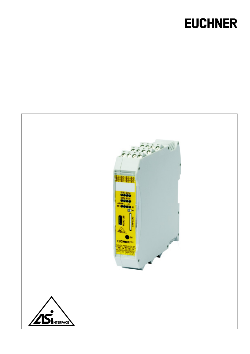
Safety Basic Monitor
User Manual
Revision date: 14.11.11
...supports the requirements for AS-i Safety up to SIL3
Page 2

Subject to modifications without notice.
Generally, this manual refers to products
without mentioning existing patents,
utility models, or trademarks.
The absence of any such references does
not indicate that a product is patent-free.
© Euchner GmbH + Co. KG
Kohlhammerstraße 16
D-70771 Leinfelden-Echterdingen
Page 3

Safety Basic Monitor
Table of Contents
Table of Contents
1 Symbol Catalog ................................. ...................................................7
1.1 Abbreviations................................................................................................... 7
2 General Remarks..................................................................................8
2.1 Product information......................................................................................... 8
2.1.1 Safety Basic Monitor........ ... .................................. .. ... .................................. ... .. ..............8
2.2 Function of this manual ..................................................................................8
2.3 Target group.....................................................................................................8
2.4 AS-i specification 3.0.......................................................................................8
3 Safety.....................................................................................................9
3.1 Experienced staff............................................................................................. 9
3.2 Application area of the device........................................................................ 9
3.3 Correct use....................................................................................................... 9
3.4 AS-i Safety at Work........................................................................................ 10
3.5 Disposal.......................................................................................................... 10
Subject to reasonable modifications due to technical advances Id.-No.: 114013 Issue date: 14.11.2011 EUCHNER GmbH + Co. KG
Kohlhammerstraße 16, D-70771 Leinfelden-Echterdingen Tel. +49/711/7597-0, Fax +49/711/753316
3
Page 4

Safety Basic Monitor
Table of Contents
4 Product Description.......................... ... .................................... .......... 11
4.1 Technical data................................................................................................11
4.2 Special characteristics of the Safety Basic Monitor...................................11
4.2.1 Derating by 24 V auxiliary power .......... .................................. ... ... ...............................11
4.3 Safety relevant data.......................................................................................12
4.4 Requirements for the voltage supply +24 VEXT (AUX) ..............................12
4.5 Front view and connections..........................................................................13
4.6 Inputs...............................................................................................................14
4.7 Outputs............................................................................................................14
4.7.1 Push button........... ... .. ................................... .. ... ............................................................14
4.8 LEDs................................................................................................................15
4.8.1 LED flashing sample .....................................................................................................16
4.9 Chip card.........................................................................................................17
4.10 AS-i Power 24 .................................................................................................17
4.11 Decoupling function.......................................................................................18
4.12 AS-i supply options........................................................................................19
4.13 Connecting of an OSSD, supplying of several OSSDs out of the same
connection (S71)20
4.13.1 Additional connection examples .................................................................................21
5 Maintenance .......................................................................................22
5.1 Controlling safe shutdowns..........................................................................22
6 AS-i Diagnostics................................................................................. 23
6.1 Introduction....................................................................................................23
6.1.1 Data of the different diagnostics modes.....................................................................23
6.2 Diagnostics mode "Consortial monitor, for replacement".........................24
6.3 Diagnostics mode "Compatibility mode with additional diagnostics data".
6.3.1 Status codes for the release circuits (OSSD) .............................................................26
6.4 Diagnostics mode "AS-i 3.0 (S-7.5.5), recommended"...............................27
6.4.1 Binary data.......... .. .................................. ... ... .................................. .. ... ..........................27
6.4.2 Transparent input data..................................................................................................27
6.4.2.1 Status codes for the release circuits (OSSD)...............................................................28
6.4.2.2 Transparent output data ...............................................................................................29
6.4.3 Acyclical data.................................................................................................................30
6.4.3.1 Vendor Specific Object 7 - device colors OSSD 1........................................................30
6.4.3.2 Vendor Specific Object 8 - device colors OSSD
6.4.3.3 Vendor Specific Object 9 - device colors at switch off OSSD 1....................................34
6.4.3.4 Vendor Specific Object 10 - device colors at switch off OSSD 1
6.4.3.5 Vendor specific object 11 … 38....................................................................................38
6.4.3.6 Vendor- specific object 110 .............. ... .................................. .. ... ..................................3 9
Subject to reasonable modifications due to technical advances Id.-No.: 114013 Issue date: 14.11.2011 EUCHNER GmbH + Co. KG
4
Kohlhammerstraße 16, D-70771 Leinfelden-Echterdingen Tel. +49/711/7597-0, Fax +49/711/753316
25
with device index assignment ...................... ... .. ..........................................................32
with device index-assignment ...... ... .................................. ... .. ... ..................................36
Page 5

Safety Basic Monitor
Table of Contents
7 Configuration of the safe inputs.......................................................40
7.1 Configuration possibilities for the safe inputs ........................................... 40
7.2 Assigning the diagnostics outputs.............................................................. 41
7.3 Safe configuration using ASIMON 3 G2....................................................... 42
7.3.1 Replacing a defective AS-i Safety Slave..................................................................... 43
7.3.2 Auto-addressing ................. .. ...... ..... ..... ..... ... ..... ..... ...... ..... ... ..... ..... ..... ... ..... ..... ...... ......44
8 Safety Requirements..........................................................................45
8.1 Safety consideration for selecting OSSD/potential-free contacts............. 45
8.2 Recommendation for improved availability of the function....................... 45
9 Accessories ........................................................................................46
Subject to reasonable modifications due to technical advances Id.-No.: 114013 Issue date: 14.11.2011 EUCHNER GmbH + Co. KG
Kohlhammerstraße 16, D-70771 Leinfelden-Echterdingen Tel. +49/711/7597-0, Fax +49/711/753316
5
Page 6
Safety Basic Monitor
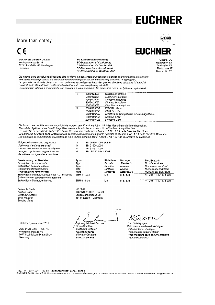
EC Declaration of Conformity
EC Declaration of Conformity
Subject to reasonable modifications due to technical advances Id.-No.: 114013 Issue date: 14.11.2011 EUCHNER GmbH + Co. KG
6
Kohlhammerstraße 16, D-70771 Leinfelden-Echterdingen Tel. +49/711/7597-0, Fax +49/711/753316
Page 7
Safety Basic Monitor
Symbol Catalog
1. Symbol Catalog
Information!
This symbol indicates important information.
Attention!
This symbol warns of a potential failure. Non-compliance may lead to interruptions of
the device, the connected peri pher al syste ms, or plan t, pote nti ally le adin g to tot al mal functioning.
Warning!
This symbol warns of an imminent danger. Non-compliance may lead to personal injuries that could be fatal or resu lt in material damages and destructi on.
1.1 Abbreviations
AS-i
I/O
EMC
PELV
PFD
SaW
OSSD
AS-interface (actuator sensor interface)
Input/output
Electromagnetic compliance
Protective extra-low voltage
Probability of failure on demand
Safety at Work, safety technic
Output Signal Switching Device, release circuit
Subject to reasonable modifications due to technical advances Id.-No.: 114013 Issue date: 14.11.2011 EUCHNER GmbH + Co. KG
Kohlhammerstraße 16, D-70771 Leinfelden-Echterdingen Tel. +49/711/7597-0, Fax +49/711/753316
7
Page 8
Safety Basic Monitor
General Remarks
2. General Remarks
Please read this chapter carefully before working with the documentation and the
Safety Monitor.
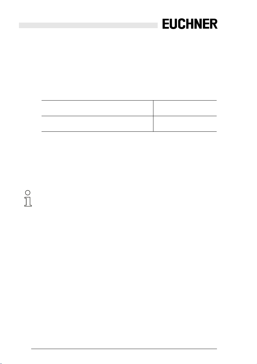
2.1 Product information
This user manual is valid for the following Euchner GmbH devices
2.1.1 Safety Basic Monitor
:
Safety Basic Monitor
without Power Supply Decoupling Unit
Safety Basic Monitor
with Power Supply Decoupling Unit
2.2 Function of this manual
This manual instructs for the safe assembly, electrical installation, addressing,
start-up as well as for the operation and for the maintenance of the Safety Monitor.
This manual does not provide instructions for operating machines, on which this
module is built in. Please view the appropriate machine manual for corresponding
information.
Information!
Additional information concerning the technical data as well as the parameterization of
the Safety Monitor can be found at http://www.euchner.de.
2.3 Target group
This manual is intended for designers, developers and operators of systems that
will be safeguarded by one or more Safety Monitors. The manual is also targeted
to people integrating Safety Monitors into machinery, performing the initial startup, or maintaining them.
2.4 AS-i specification 3.0
The AS-i 3.0 devices already fulfil the AS-i specification 3.0.
The previous specifications (2.1 and 2.0) are supported as well.
SBM-11-S08
SBM-11-N08
Subject to reasonable modifications due to technical advances Id.-No.: 114013 Issue date: 14.11.2011 EUCHNER GmbH + Co. KG
8
Kohlhammerstraße 16, D-70771 Leinfelden-Echterdingen Tel. +49/711/7597-0, Fax +49/711/753316
Page 9

Safety Basic Monitor
Safety
3. Safety
This chapter contains user safety information.
Warning!
Please read this chapter carefull y before using th e Safety Basic Monitor in combination with other machine safeguarding components on protected machinery.
3.1 Experienced staff
The Safety Basic Monitor must only be installed, operated, and maintained by
qualified staff.
Qualified is a person who
• has a suitable technical education
• has been instructed in operating the machinery and has been informed about
the valid safety guidelines by the machinery operator
• has access to the user manual.
3.2 Application area of the device
The Safety Monitor combines a SaW I/O module and a Safety Monitor in one
IP20 enclosure.
Special characteristics:
• Safety Monitor in IP20
• up to 8 / 4 local safe inputs
optionally the safe inputs will be used as well as standard inputs and signal
outputs
• 2 (4) local electronical safe outputs
• safe AS-i outputs are supported
max. 8 independent AS-i outputs
multiple safe AS-i outputs possible via a single address
• chip card for storage of configuration data
The module is certified according to EN 62 061, SIL 3, and EN 13 849, performance level "e".
3.3 Correct use
The Safety Basic Monitor must only be used as defined in chap. <Application
area of the device>. The Safety Basic Monitor must only be used on the system,
at which it was installed in accordance with this manual by adept personnel.
Information!
If used in a way differing from this description or if the device has been changed in any
way – even during installation – any war ranty claims with respect to Euchner GmbH
are invalid.
Subject to reasonable modifications due to technical advances Id.-No.: 114013 Issue date: 14.11.2011 EUCHNER GmbH + Co. KG
Kohlhammerstraße 16, D-70771 Leinfelden-Echterdingen Tel. +49/711/7597-0, Fax +49/711/753316
9
Page 10
Safety Basic Monitor
Safety
3.4 AS-i Safety at Work
AS-i Safety at Work combines safe and non-safe data on a bus system. The classification AS-i Safety at Work identifies the safe data transfer that enables the integration of safety procedures in an AS-i network.
The components of AS-i Safety at Work conform to EN 50295 and are compatible
with all other AS-i components. Therefore, existing AS-i applications can easily
be extended with safety-relevant functions.
AS-i Safety at Work always requires a Safety Monitor (as a stand-alone device or
integrated into a Gateway), that evaluates the safe signals on the bus, and a safe
AS-Interface bus connection, that enables the transfer of safe signals from safety-relevant components (AS-i SaW input).
Additionally, decentralized safe AS-I SaW outputs can be added. Controlled by
the Safety Monitor these outputs can be used to safely switch off safe actuators.
Several Safety Monitors and safe input and output slaves can be used on an
AS-i system. At the same time, the Safety Monitors can be parameterized and,
thus, be checked through AS-i and the configuration software.
Information!
By utilizing AS-i Safety at Work safety requirements up to category 4 according to
EN 954-1 and additionally performance level "e" according to EN 13 849 as well as SIL
3 according to EN 62 061 can be satisfied.
In order to satisfy the requirements of these safety categories, all peripheral components, for instance the Safety Monitors, all safe bus connections, and all connected sensors must satisfy these standards.
3.5 Disposal
Information!
Electronic waste is hazardous waste. Please comply with all local ordinances wh en
disposing this product!
The device does not contain batteries that need to be removed before disp osing it.
Subject to reasonable modifications due to technical advances Id.-No.: 114013 Issue date: 14.11.2011 EUCHNER GmbH + Co. KG
10
Kohlhammerstraße 16, D-70771 Leinfelden-Echterdingen Tel. +49/711/7597-0, Fax +49/711/753316
Page 11
Safety Basic Monitor
Product Description
4. Product Description
This chapter is intended to inform the reader about the special characteristics of
the Safety Monitor. It describes the design and the functionality of the devices.
Warning!
This chapter must be read before installation and operation of the device in conjunction
with other safety components on protected machinery.
4.1 Technical data
The technical data are placed in the data sheet. Please view the current version
on the web page: www.euchner.de
4.2 Special characteristics of the Safety Basic Monitor
• The module uses only the necessary AS-i addresses.
• Various configuration possibilities for the safe inputs (see chap. <Configuration possibilities for the safe inputs>).
• No limitation of cable length at safe inputs (the maximum loop resistance is
150 Ohm).
• A safe signal exchange of 2 signals between Safety Monitor and AS-i Safety
Module as well as between two AS-i Safety Modules are possible.
• LED displays acc. to other Safety Slaves or to the Monitor.
• Simple configuration of the AS-i-Slaves using ASIMON.
• Chipcard for the simple exchange.
• Micro-USB port for configuring with AS-i-Control-Tools and ASIMON.
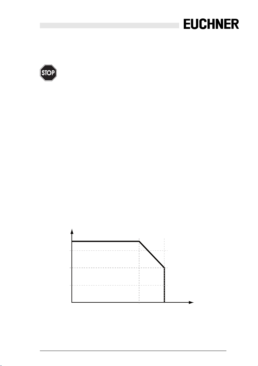
4.2.1 Derating by 24 V auxiliary power
I
AUX, max [A]
3,5
3
2
1
T
[°C]
40
Subject to reasonable modifications due to technical advances Id.-No.: 114013 Issue date: 14.11.2011 EUCHNER GmbH + Co. KG
Kohlhammerstraße 16, D-70771 Leinfelden-Echterdingen Tel. +49/711/7597-0, Fax +49/711/753316
55
amb
11
Page 12
Safety Basic Monitor
Product Description
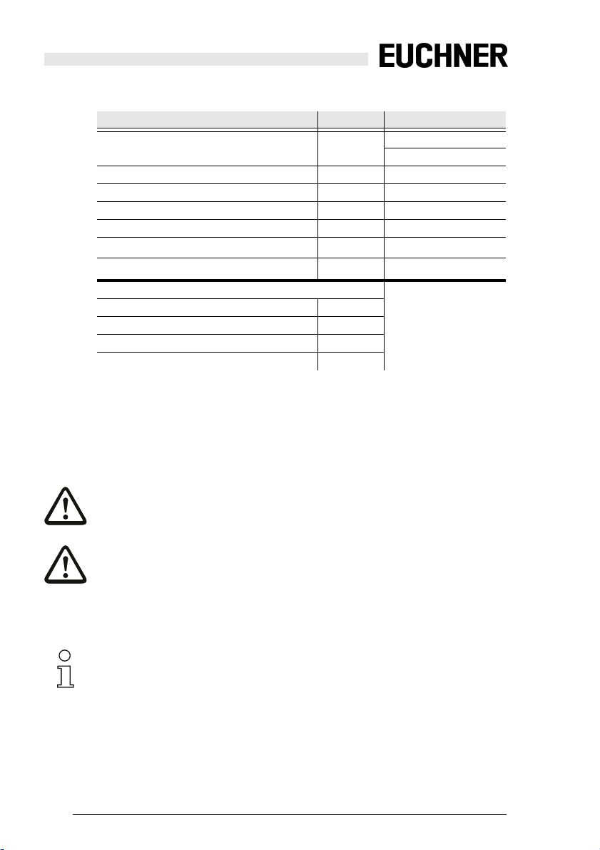
4.3 Safety relevant data
Characteristics Value Standard
Safety category 4 EN 954-1
Performance Level (PL) e EN 13 849-1:2008
Safety Integrity Level (SIL) 3 IEC 61 508, EN 62 061
Service life (TM) [year] 20 EN 13 849-1:2008
Maximal power-on time (month) 12 IEC 61 508
PFD
1
PFH
D
Max. reaction time [ms]
AS-i input slave → local output 40
local input → local output 20
local input → AS-i code sequenc e 26
AS-i input slave → AS-i code sequence 45
1. Probability of a dangerous loss per hour.
To determine the safety characteristics (PFD and PFH), the values of all components using this function are to be considered. The module provides no significant
contribution to the PFD or PFH values of the complete system. For the values of
other components, please refer to relevant documentation.
9,58 x 10
5,08 x 10
EN 13 849-1:2008
-7
EN 62 061
-9
IEC 61 508, EN 62 061
IEC 61 508
Tab. 4-1.
Attention!
If the option „augmented reliability“ is selected the response time can extend.
Attention!
Error states of the remote o utput s used in the safe conf igurat ion can be elimin ated by
starting and stopping the monitor.
4.4 Requirements for the voltage supply +24 V
EXT
(AUX)
Information!
The externally connectable c ircui ts are to be sepa rated f rom the net absol utely re liabl e!
The power supply +24 V
Subject to reasonable modifications due to technical advances Id.-No.: 114013 Issue date: 14.11.2011 EUCHNER GmbH + Co. KG
12
Kohlhammerstraße 16, D-70771 Leinfelden-Echterdingen Tel. +49/711/7597-0, Fax +49/711/753316
may only occur via SELV or PELV networks.
EXT
Page 13
Safety Basic Monitor
Product Description
Attention!
The power supply for the 24 V supply mu st also hav e iso la tio n pe r IEC 60 74 2 an d be
able to handle momentary power interr uptions of up to 20 ms. The maximum outp ut
voltage of the power supply must also be less than 42 V in case of a fault.
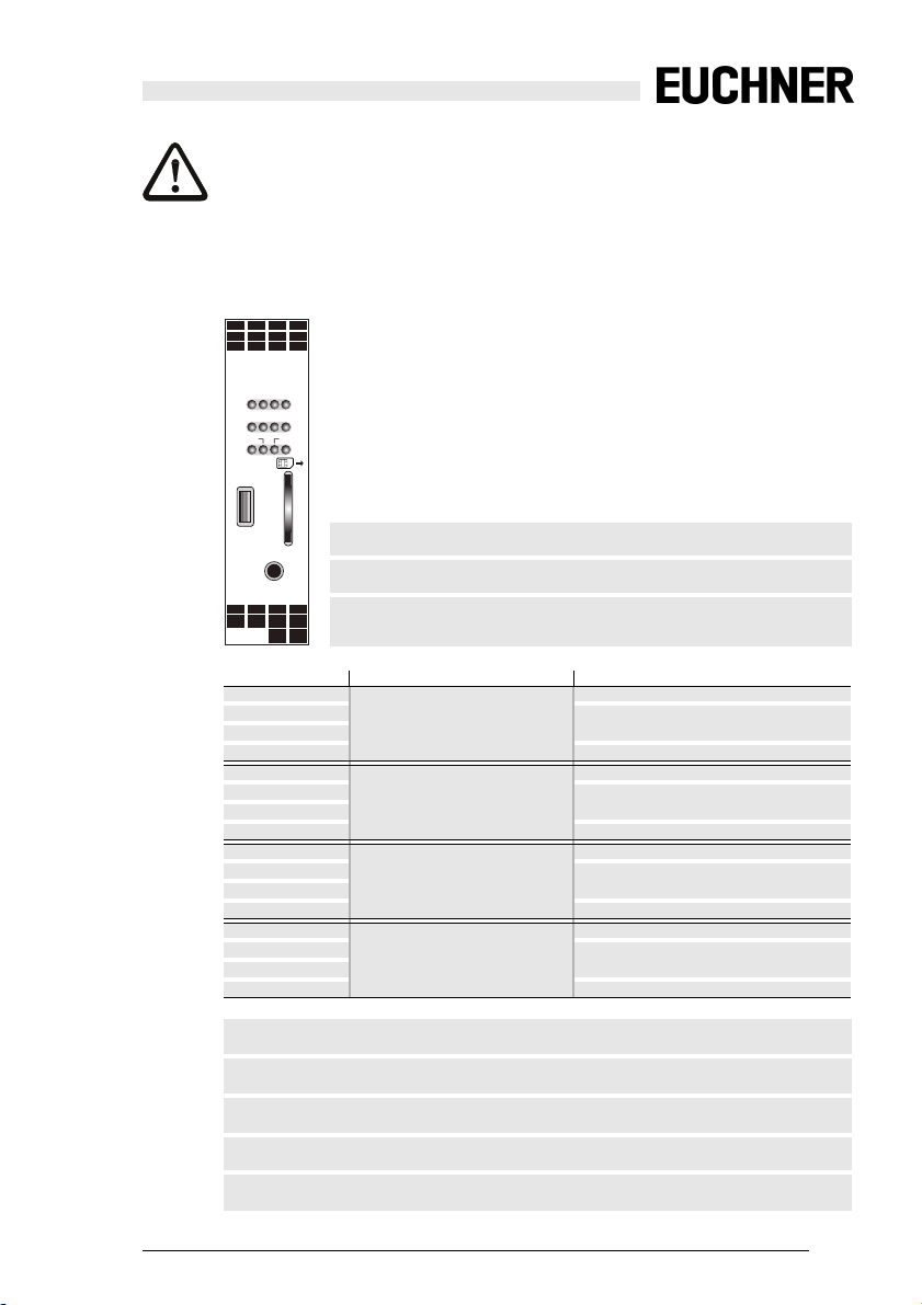
4.5 Front view and connections
22 S 21 S 12 S 11
S
S
42 S 41 S 32 S 31
62 S 61 S 52 S 51
S
S4S3S2
S1
S8S7S6
S5
AS-i M
O1
O2
SM
CHIP CARD
MICRO USB
S 71 S 72 S 81 S 82
1.14
0 V
1
ext. out
ext. out
–
+
ASI
ASI
connection 2-channel direction
S11
S12
S21
S22 output
S31
S32
S41
S42 output
S51
S52
S61
S62 output
S71
S72
S81
S82 output
Micro USB
Micro USB interface
SET
SET
service button // bouton service // compasse service // botón servicio
Chip Card
0 V
2
2.14
chip card
ext. out
ext. out
–
AUX
AUX+
ext. in
ext. in
2-channel safety input 1
2-channel safety input 2
2-channel safety input 3
2-channel safety input 4
output
input
output
input
output
input
output
input
1.14
ext.out
Safe semiconductor output 1
2.14
ext.out
Safe semiconductor output 2
0V
ext.out
ground connection for semiconductor output
ASI+, ASI–
AS-i connection
AUX+, AUX–
connection to ext. 24 VDC
Subject to reasonable modifications due to technical advances Id.-No.: 114013 Issue date: 14.11.2011 EUCHNER GmbH + Co. KG
Kohlhammerstraße 16, D-70771 Leinfelden-Echterdingen Tel. +49/711/7597-0, Fax +49/711/753316
13
Page 14
Safety Basic Monitor
Product Description
4.6 Inputs
The inputs are powered by the 24 V auxiliary power supply. Each input consists of
two terminals: a passive input pin and an active test pulse output. A switch connects the two pins together.
Two of the safe inputs are also usable as inputs for OSSDs, and the others for potential-free contacts only.
Each safe input can also be configured as two standard inputs. The test pulse
outputs can also be switched as diagnostics outputs (non safety).
For additional information see chap. <Additional connection examples>.
4.7 Outputs
The outputs must be powered by a PELV power supply.
The maximum output current is 700 mA per output, and the outputs are suitable
for DC13 loads.
The plus side of the output load is at 1.14 or 2.14. The minus side of the output
load must be connected to the 0Vext out.
The lines between the module and the load must be routed so that no extraneous
voltages caused by damaged insulation can inadvertently switch the load.
4.7.1 Push button
The Teach/Service button (SET) has the following functions:
• Error acknowledgement
• PC-less substitution of Safety Slaves
Keystroke Description
< 1s Error acknowledgement
> 1s Changing to projecting mode
The master goes into projecting mode and the safety unit is ready to
learn a code sequence (analogous to learning using the Set key on
standard monitors).
< 1s
Projecting mode is exited without ch anges.
> 1s Saving the actual configuration in the master
Teaching the individual code sequence of a newly safety-configured
slave when exactly one safety-configured slave is replaced.
For additional information see Tab.
Subject to reasonable modifications due to technical advances Id.-No.: 114013 Issue date: 14.11.2011 EUCHNER GmbH + Co. KG
14
Kohlhammerstraße 16, D-70771 Leinfelden-Echterdingen Tel. +49/711/7597-0, Fax +49/711/753316
<LEDs>.
Page 15

Safety Basic Monitor
Product Description
4.8 LEDs
LEDs Status Signal // Description
S1, S2,
S3, S4,
S5, S6,
S7, S8
(yellow)
1
SM
(green)
contact (S1 … S8) open
1 Hz
cross circuit //
contact (S1 … S8) closed
AS-i supply power not OK
1 Hz
’protective mode’ and ASIMON active
(red)
1 Hz
’configuration mode’ and ASIMON active //
’configuration mode’ active
2 Hz
(yellow)
at least 1 device in state ’red flashing’ or ’yellow flashing’
2 Hz
1 Hz
service button, state: ’teach-error’
service button, state: ’ready’
2
AS-i M
(red)
off-line, monitor mode
1 Hz
’peripheral fault’ without ’config error’
’config error’, auto addressing not possible
1 Hz
(green)
’config error’, auto addressing possible
2 Hz
master: ’protective mode’, no error //
1 Hz
master: ’configuration mode’, no error //
3
O1, O2
(yellow)
output (O1, O2) off
1 Hz
restart inhibit
8 Hz
correctable error codition
output (O1, O2) on
(red)
SM,
AS-i M,
O1, O2
no auxiliary voltage
competing master active
1 Hz
1. ’yellow’ has higher priority than ’red’ and ’green’ and will displayed preferentially.
Tab. 4-2. LEDs
Subject to reasonable modifications due to technical advances Id.-No.: 114013 Issue date: 14.11.2011 EUCHNER GmbH + Co. KG
Kohlhammerstraße 16, D-70771 Leinfelden-Echterdingen Tel. +49/711/7597-0, Fax +49/711/753316
15
Page 16

Safety Basic Monitor
Product Description
2. If ’config-error’ and ’p eripheral fault’ occur simultaneously, only ’config-error’ is displayed.
3. ’red’ has higher priority than ’yellow’
4.8.1 LED flashing sample
operation LEDs frequency Status
chip card will be written
(yellow)
S1-S4 2 x 1 Hz
S5-S8
internal error
(red)
data on the chip card + device different
(yellow)
chip card defect
(yellow)
legend
flashing in common mode
flashing in push-pull mode
off
on
SM, AS-i M,
O1, O2
S1-S4 —
S5-S8 —
SM, AS-i M,
O1, O2
S1-S4 1 Hz
S5-S8
SM, AS-i M,
O1, O2
S1-S4 1 Hz
S5-S8
SM, AS-i M,
O1, O2
table 4-2
table 4-2
table 4-2
8Hz
Tab. 4-3.
standard view acc. to table 4-2
Subject to reasonable modifications due to technical advances Id.-No.: 114013 Issue date: 14.11.2011 EUCHNER GmbH + Co. KG
16
Kohlhammerstraße 16, D-70771 Leinfelden-Echterdingen Tel. +49/711/7597-0, Fax +49/711/753316
Tab. 4-4.
Page 17

Safety Basic Monitor
Product Description
4.9 Chip card
The chip card stores the addresses of the slaves. All programming operations are
stored both in the module and on the chip card.
• The device can operate both with and without a chip card.
• If a blank chip card is plugged into a programmed module, the configuration
of the module is stored on the chip card.
• If a non-blank chip card is plugged into an non-programmed module, the configuration of the chip card is transmitted to the module. The changes do not
become effective until the module is restarted.
• If a non-blank chip card is plugged into a different programmed module, the
configurations do not agree and an error message is displayed.
4.10 AS-i Power 24
only
SBM-11-N08 !
• internal decoupling network / AS-i voltage is generated out of 24 V
• no external AS-i power supply, no external decoupling unit required!
• maximum 0,5 A for AS-i available using internal decoupling network
• switching between internal and external decoupling.
directly
ext
Subject to reasonable modifications due to technical advances Id.-No.: 114013 Issue date: 14.11.2011 EUCHNER GmbH + Co. KG
Kohlhammerstraße 16, D-70771 Leinfelden-Echterdingen Tel. +49/711/7597-0, Fax +49/711/753316
17
Page 18

Safety Basic Monitor
Product Description
4.11 Decoupling function
only
SBM-11-N08 !
Bei activating the option "Operation without AS-i power supply" you can use the
AS-i Power24V data decoupling network instead of an external AS-i power supply.
Information!
The internal decoupling unit can supply a maximum current of 500 mA.
Simply open the ‘Monitor/-Bus Information’ window in ASIMON, select the tab
’Safety Basis Monitor’ and activate the check box "Operation without AS-i power
supply".
ASIMON 3 G2 Software
Information!
Please note additional information in the manual for the ASIMON software.
Subject to reasonable modifications due to technical advances Id.-No.: 114013 Issue date: 14.11.2011 EUCHNER GmbH + Co. KG
18
Kohlhammerstraße 16, D-70771 Leinfelden-Echterdingen Tel. +49/711/7597-0, Fax +49/711/753316
Page 19

Safety Basic Monitor
Product Description
4.12 AS-i supply options
SBM-11-N08 SBM-11-S08 +
internal decoupling external decoupling
SBM-11-N08
AS-i -
AS-i +
Ground
AS-i Power Supply
–
–
+
AUX
ASI
ASI
AUX+
ext. in
ext. in
Safety Basis Monitor
–
+
AUX
(24 VDC)
PELV
AS-i Power Supply
AS-i -
AS-i +
Ground
–
–
+
AUX
ASI
ASI
AUX+
ext. in
ext. in
Safety Basis Monitor
–
+
AUX
(24 VDC)
PELV
Tab. 4-5.
Attention!
The AS-I power supply for the AS- I components must have iso lation per IEC 60 742
and be able to handle momentary power interruptions of up to 20 ms. The power supply for the 24 V supply must also ha ve is olat ion pe r I EC 60 742 a nd be a ble to ha nd le
momentary power interruptions of up to 20 ms. The maximum output voltage of the
power supply must also be less than 42 V in case of a fault.
Subject to reasonable modifications due to technical advances Id.-No.: 114013 Issue date: 14.11.2011 EUCHNER GmbH + Co. KG
Kohlhammerstraße 16, D-70771 Leinfelden-Echterdingen Tel. +49/711/7597-0, Fax +49/711/753316
19
Page 20

Safety Basic Monitor
Product Description
4.13 Connecting of an OSSD, supplying of several OSSDs out of the same connection (S71)
22 S 21 S 12 S 11
S
S
42 S 41 S 32 S 31
S
62 S 61 S 52 S 51
S52S61
OSSD2
OSSD1
24V
0V
Receiver
Transmitter
24V
0V
FE
FE
S71
S72
S81
S 71 S 72 S 81 S 82
0
2.14
1.14
V
ext. out
ext. out
ext. out
–
AUX+
+
ASI
ASI
ext. in
–
+
+
ASI
AUX
PELV
0 V
ext. out
–
AUX
ext. in
–
(24 VDC)
24V
OSSD1
OSSD2
0V
Receiver
Transmitter
24V
0V
FEFE
0V
Subject to reasonable modifications due to technical advances Id.-No.: 114013 Issue date: 14.11.2011 EUCHNER GmbH + Co. KG
20
Kohlhammerstraße 16, D-70771 Leinfelden-Echterdingen Tel. +49/711/7597-0, Fax +49/711/753316
Page 21

Safety Basic Monitor
Product Description
4.13.1 Additional connection examples
safety input standard inputs message outputs
22 S 21 S 12 S 11
22 S 21 S 12 S 11
S
S
42 S 41 S 32 S 31
62 S 61 S 52 S 51
S
S
S
42 S 41 S 32 S 31
S
62 S 61 S 52 S 51
S52S61
22 S 21 S 12 S 11
S
42 S 41 S 32 S 31
S
S
62 S 61 S 52 S 51
S62
S51
I
max
= 10mA
SPS
PLC
IN
IN
0V
S 71 S 72 S 81 S 82
1.14
ext. out
+
ASI
–
+
ASI
contactor
22 S 21 S 12 S 11
S
42 S 41 S 32 S 31
S
S
62 S 61 S 52 S 51
ext.out
1.14
0Vext.out
S 71 S 72 S 81 S 82
2.14
0
1.14
V
ext. out
ext. out
ext. out
–
AUX+
+
ASI
ASI
ext. in
–
+
+
ASI
0
V
ext. out
–
ASI
–
AUX
(PELV)
ext. out
AUX
0 V
ext. in
2.14
ext. out
AUX+
ext. in
+
–
0 V
ext. out
AUX
ext. in
–
AUX
(PELV)
(24 VDC)
–
(24 VDC)
S32
AUX+
K1
K2
+
L1 L2 L3
Motor
ext. in
S 71 S 72 S 81 S 82
2.14
0
1.14
V
ext. out
ext. out
ext. out
–
AUX+
+
ASI
ASI
ext. in
–
+
AUX
ASI
0 V
ext. out
–
AUX
ext. in
–
(24 VDC)
(PELV)
ASIMON
ext. in
AUX+
S 71 S 72 S 81 S 82
1.14
ext. out
ASI
+
+
ASI
0 V
2.14
0
V
ext. out
ext. out
ext. out
–
–
AUX
AUX+
ASI
ext. in
ext. in
–
–
+
AUX
(24 VDC)
(PELV)
Tab. 4-6. Additional connection examples
ext. in
AUX-
Subject to reasonable modifications due to technical advances Id.-No.: 114013 Issue date: 14.11.2011 EUCHNER GmbH + Co. KG
Kohlhammerstraße 16, D-70771 Leinfelden-Echterdingen Tel. +49/711/7597-0, Fax +49/711/753316
21
Page 22

Safety Basic Monitor
Maintenance
5. Maintenance
5.1 Controlling safe shutdowns
The plant safety engineer is responsible for verifying that the Safety Basic Monitor works correctly as part of the safety system.
At least once a year it is necessary to verify the safe shutdown by initiating associated safety-related sensors or switchs:
Attention!
Press each safety-related AS-i slave and watch the reaction of the output circuits of the
AS-i Safety Monitor.
Attention!
Check the maximum activated time an d the tot al o per ati ng time . These va lu es de pe nd
on the PFD value chosen for the total failure probability. Please refer to the information
in chap. Safety relevant data.
After reaching the projected maximum operating time (three, six, or twelve months) the
entire safety system must be checked for proper operation.
After reaching the projecte d tot al usag e time (2 0 yea rs) t he de vice must be c hec ked b y
the manufacturer concerning it s proper operation.
Subject to reasonable modifications due to technical advances Id.-No.: 114013 Issue date: 14.11.2011 EUCHNER GmbH + Co. KG
22
Kohlhammerstraße 16, D-70771 Leinfelden-Echterdingen Tel. +49/711/7597-0, Fax +49/711/753316
Page 23

Safety Basic Monitor
AS-i Diagnostics
6. AS-i Diagnostics
6.1 Introduction
The device provides two different diagnostics modes:
• Consortial monitor, for replacement (see chap. 6.2)
• Compatibility mode with additional diagnostics data (see chap. 6.3)
• AS-i 3.0 (S-7.5.5), recommended (see chap. 6.4)
The respective diagnostics mode is selected using the ASIMON software.
Simply open the ‘Monitor/-Bus Information’ window in ASIMON
Select the ‘Diagnostics/Service’ tab
There select the required diagnostics mode.
6.1.1 Data of the different diagnostics modes
AS-i 3.0 (S-7.5.5), recommended
(see chap. 6.4)
base address S-7.5 communication
(see chap. 6.4.1 …
6.4.3)
simulate slave 1
state OSSD1+OSSD2 state
base address+1
simulate slave 2
base address+2
simulate slave 3
base address+3
S-7.F slave,
input data = 0
S-7.F slave,
input data = 0
Consortial monitor,
for replacement
(see chap. 6.2)
consortial diagnostics (chap. 7.3.2 …
7.3.6 software manual)
OSSD1+OSSD2
S-7.F slave,
input data = 0
S-7.F slave,
input data = 0
Compatibility mode
with additional diagnostics data
(see chap. 6.3)
consortial diagnostics (chap. 7.3.2 …
7.3.6 software manual)
state
OSSD1+OSSD2
S-7.3.0.C slave (see
chap. 6.3)
S-7.3.1.C slave (see
chap. 6.3)
Tab. 6-7.
Subject to reasonable modifications due to technical advances Id.-No.: 114013 Issue date: 14.11.2011 EUCHNER GmbH + Co. KG
Kohlhammerstraße 16, D-70771 Leinfelden-Echterdingen Tel. +49/711/7597-0, Fax +49/711/753316
23
Page 24

Safety Basic Monitor
AS-i Diagnostics
6.2 Diagnostics mode "Consortial monitor, for replacement"
Information!
Diagnostics type: compatibility mode for Safety Basic Monitors starting with the SafetyVersion ’SV4.3’.
Consortial diagnostics, with S-7-3 diagnostics added.
Address Meanining
basic address Consortial diagnostics, limited to 48 devices
simulated slave 1 status OSSD 1 and OSSD 2
simulated slave 2 S-7.F slave, input data = 0
simulated slave 3
Simulated slave 1: status OSSD 1 and OSSD 2 (binary data)
Data bit content
D0 status relay output 1
D1 status message output 1
D2 status relay output 2
D3 status message output 2
Tab. 6-8.
Tab. 6-9.
Subject to reasonable modifications due to technical advances Id.-No.: 114013 Issue date: 14.11.2011 EUCHNER GmbH + Co. KG
24
Kohlhammerstraße 16, D-70771 Leinfelden-Echterdingen Tel. +49/711/7597-0, Fax +49/711/753316
Page 25

Safety Basic Monitor
AS-i Diagnostics
6.3 Diagnostics mode "Compatibility mode with additional diagnostics data"
Information!
Diagnostics type: compatibility mode for Safety Basic Monitors starting with the SafetyVersion ’SV4.3’.
Address Meanining
basic address Consortial diagnostics, limited to 48 devices
simulated slave 1 status OSSD 1 and OSSD 2
simulated slave 2 S-7.3 OSSD diagnostics, 4 channel transparent input,
Profil S-7.3.0.C
simulated slave 3 S-7.3 SaW slave diagnostics, 4 channel transparent input,
profile 7.3.1.C
Tab. 6-10.
Simulated slave 1: status OSSD 1 and OSSD 2 (binary data)
Data bit content
D0 status relay output 1
D1 status message output 1
D2 status relay output 2
D3 status message output 2
Tab. 6-11.
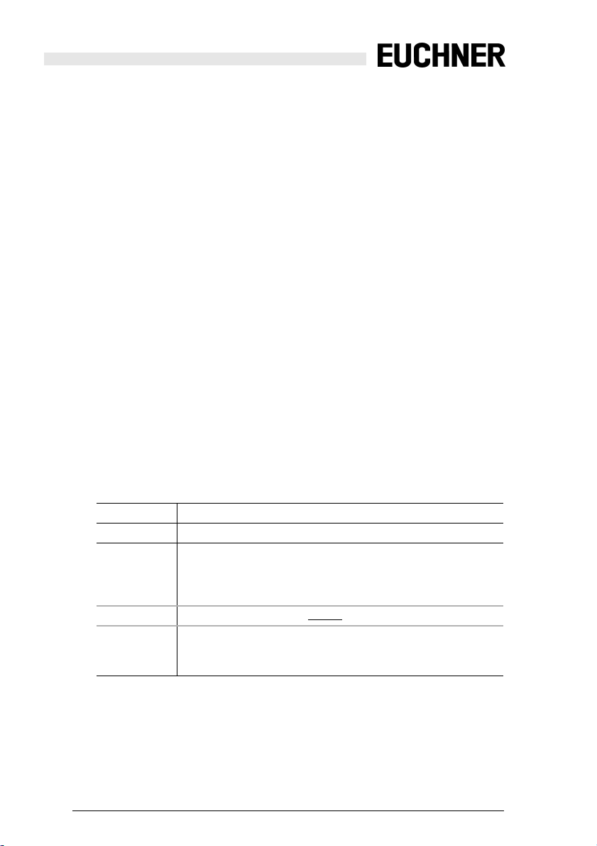
Simulated slave 2 (7.3.0.C): OSSD diagnostics
15 14 13 12 11 10 9 8 7 6 5 4 3 2 1 0
CH1 Safety status OSSD 2 Safety status OSSD 1
CH2 Safety status OSSD 4 Safety status OSSD 3
CH3 Safety status OSSD 6 Safety status OSSD 5
CH4 S8 S7 S6 S5 S4 S3 S2 S1 Safety status OSSD 7
When switch S1 … S8 is closed a ‘1’ is entered in the corresponding position.
The Safety Status is defined as follows:
Bit 7 6 5 4 3 2 1 0
1: not less than
one device red
flashing
Subject to reasonable modifications due to technical advances Id.-No.: 114013 Issue date: 14.11.2011 EUCHNER GmbH + Co. KG
Kohlhammerstraße 16, D-70771 Leinfelden-Echterdingen Tel. +49/711/7597-0, Fax +49/711/753316
1: not less than one
device yellow flashing
n/a n/a OSSD color
(siehe Tab. Status codes for the
release circuits (OSSD))
Tab. 6-12.
Tab. 6-13.
25
Page 26
Safety Basic Monitor
AS-i Diagnostics
^
Simulated slave 3 (S-7.3.1.C)::SaW slave diagnostics
15 14 13 12 11 10 9 8 7 6 5 4 3 2 1 0
Slv 7 Slv 6 Slv 5 Slv 4 Slv 3 Slv 2 Slv 1
CH1
Slv15 Slv14 Slv13 Slv12 Slv11 Slv10 Slv9 Slv8
CH2
Slv 23 Slv 22 Slv 21 Slv 20 Slv 19 Slv 18 Slv 17 Slv 16
CH3
Slv 31 Slv 30 Slv 29 Slv 28 Slv 27 Slv 26 Slv 25 Slv 24
CH4
For each safe slave (ID=B) the status of the code sequence is entered as seen by
the Master. Code sequence errors are not detected here. For non-safe slaves ‘00’
is entered.
Bit-combination meaning
00 Not a safe slave or save slave with zero sequence, both switches
open
01 Safe slave, switch for upper bits open
10 Safe slave, switch for lower bits op en
11 Safe slave, both switches closed
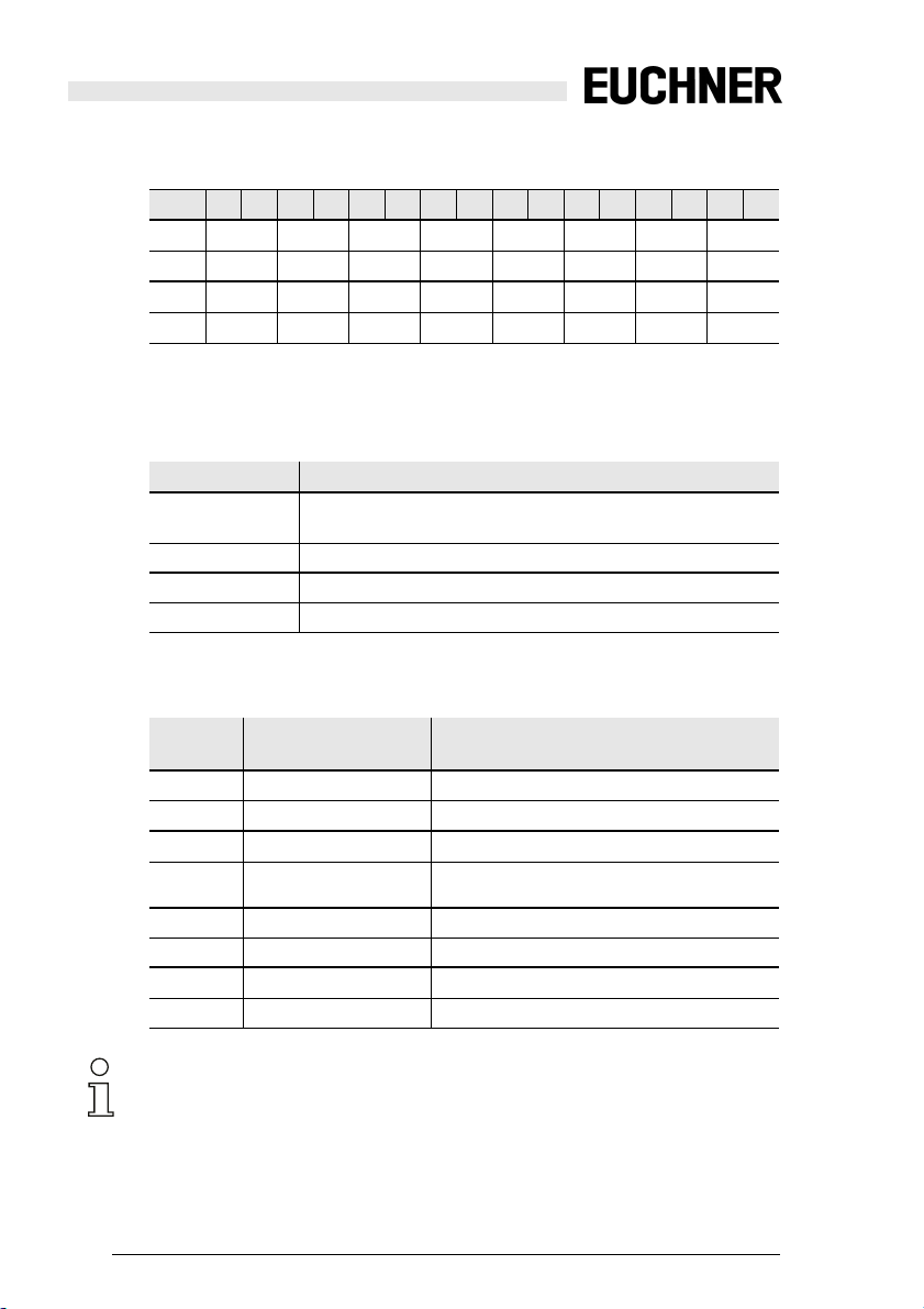
6.3.1 Status codes for the release circuits (OSSD)
Tab. 6-14.
Tab. 6-15.
Code
Status / color Description
bit [3..0]
0 green permanent light in g Output on
1 green flashing
2 continuous yellow
3 yellow flashing
delay time is running at stop category 1
start-up/restart-disable active
External test required / acknowledgement /
Turn-on delay active
4 red permanent lighting Output off
5 red flashing Error
6grey or off
output not projected
7 ... F reserved
Information!
Monitors which support less than 8 release circuits do not set all release circuits
present to “grey".
Subject to reasonable modifications due to technical advances Id.-No.: 114013 Issue date: 14.11.2011 EUCHNER GmbH + Co. KG
26
Kohlhammerstraße 16, D-70771 Leinfelden-Echterdingen Tel. +49/711/7597-0, Fax +49/711/753316
Tab. 6-16.
Page 27

Safety Basic Monitor
AS-i Diagnostics
6.4 Diagnostics mode "AS-i 3.0 (S-7.5.5), recommended"
6.4.1 Binary data
D3 D2 D1 D0
input data Serial
output data – – Serial
communication
Serial
communication
1: Output 2
either turned off
or flashing green
communication
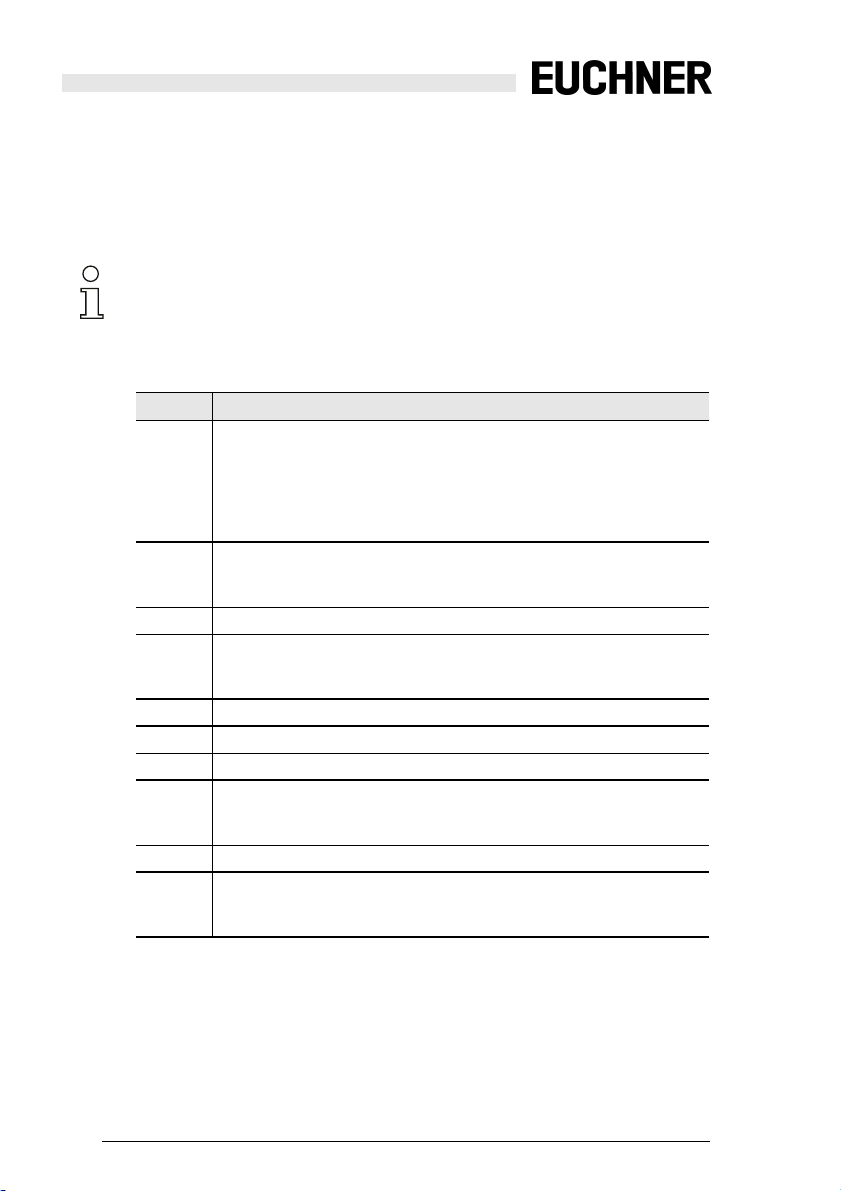
6.4.2 Transparent input data
Using profile 7.5.5 it is possible to poll the status of the release circuits (OSSD
Safety Control Status) of the Safety Monitor cyclically (see table below). To do this
you must assign an AS-i address (basic address) to the Safety Monitor and assign an 8-byte analog input slave to the basic address of the Safety Monitor.
These 8 bytes contain the diagnostics data (transparent input data) as shown in
the following table:
1: Output 1
either turned off
or flashing green
Serial
communication
Tab. 6-17.
channel
2152142132122112102928272625242322212
0
CH0 AS-i circuit 2 AS-i circuit 1
AU MO S8 S7 S6 S5 S4 S3 S2 S1 UA1 UA
CH1 Safety status
OSSD 4
CH2 Safety status
OSSD 8
Safety status
OSSD 3
Safety status
OSSD 7
Safety status
OSSD 2
Safety status
OSSD 6
Safety status
OSSD 1
Safety status
OSSD 5
CH3 OSSD 8 OSSD 7 OSSD 6 OSSD 5 OSSD 4 OSSD 3 OSSD 2 OSSD 1
RF YF RF YF RF YF RF YF RF YF RF YF RF YF RF YF
Tab. 6-18.
Channel ‘0’ of the transparent input data describes the status of the two AS-i segments. The upper 8 bits describe the status of AS-i segment 2, the lower 8 the
status of AS-i segment 1.
In Channels 1 and 2 the colors of the release circuits then follow (only two are
used at present).
Channel 3 then indicates combined information for the colors of the devices in the
release circuits.
Then the information is listed individually:
MO Operating
mode
1: Safety Monitor in protected operating mode
0: Safety Monitor in configur ation operation
UA UAS-i AS-i voltage greater than 18 V
1: voltage is sufficient
0: voltage is not sufficient
Subject to reasonable modifications due to technical advances Id.-No.: 114013 Issue date: 14.11.2011 EUCHNER GmbH + Co. KG
Kohlhammerstraße 16, D-70771 Leinfelden-Echterdingen Tel. +49/711/7597-0, Fax +49/711/753316
27
Page 28

Safety Basic Monitor
AS-i Diagnostics
AU AUX 24V
The 24 V for supplying the safe outputs is present
1: 24 V for supplying the safe outputs is present
0: 24 V for supplying the safe outputs is not present
UA1 Warning AS-i voltage OK, but less than 22.5 V
1: AS-i voltage greater than 22.5 V
0: AS-i voltage less than 22,5 V
S1-S8Switch S1-S8: for a closed switch S1 … S8 '1' is entered at the correspond-
ing position.
Channels 1 and 2 describe the states of the respective release circuits (OSSD’s)
of the Safety Monitor. For status codes and colors see section Status codes for
the release circuits (OSSD).
Channel 3 contains information as to whether there are warnings or faults in a release circuit for one or more devices assigned to this release circuit. The meanings are as follows:
YF Yellow flashing At least one of the devices associated with this release cir-
cuit is in the yellow flashing state
RF Red flashing At least one of the devices associated with this release cir-
cuit is in the red flashing state
6.4.2.1 Status codes for the release circuits (OSSD)
Code
status / color Description
bit [3..0]
0
1 green flashing
2 yellow permanent light-
green permanent lighting
output on
delay time is running at stop category 1
start-up/restart-disable active
ing
3 yellow flashing
external test necessary / acknowledgement
/ start delay active
4 red permanent lighting
5 red flashing
6grey or off
output off
error
output not projected
7 ... F reserved
Tab. 6-19.
Tab. 6-20.
Subject to reasonable modifications due to technical advances Id.-No.: 114013 Issue date: 14.11.2011 EUCHNER GmbH + Co. KG
28
Kohlhammerstraße 16, D-70771 Leinfelden-Echterdingen Tel. +49/711/7597-0, Fax +49/711/753316
Page 29

Safety Basic Monitor
AS-i Diagnostics
6.4.2.2 Transparent output data
The transparent output data are available there to the safe unit as non-safe additional bits, for example for Start buttons. They are linked with the input bits of the
input configured as non-safe terminals.
Ch
2152142132122112102928272625242322212
0 reserved S8S7S6S5 S4 S3 S2 S1
Tab. 6-21.
0
Subject to reasonable modifications due to technical advances Id.-No.: 114013 Issue date: 14.11.2011 EUCHNER GmbH + Co. KG
Kohlhammerstraße 16, D-70771 Leinfelden-Echterdingen Tel. +49/711/7597-0, Fax +49/711/753316
29
Page 30
Safety Basic Monitor
AS-i Diagnostics
6.4.3 Acyclical data
6.4.3.1 Vendor Specific Object 7 - device colors OSSD 1 Read only
This object contains the colors and additional information for all release circuits
for all devices assigned to Release Circuit 1.
Information!
If not all 128 devices are assigned, the Monitor can shorten the S-7.5.5 telegram in
order to save transmission time.
Coding for the states and colors
Byte Meaning
1
bit 0 0=configuration mode, 1=protect ing mode
bit 3 … 1 reserved, 0
bit 4 status S12
bit 5 status S21
bit 6 status S32
bit 7 status S41
2
relay status, output 1+2
bit 3 … 0 status output 1
bit 7 … 4 status output 2
3…8
...
9
relay status output 15+16
bit 3 … 0 status output 15
bit 7 … 4 status output 16
10
bit field for devices which are present. Device 7 … 0
11 ... 40
...
41
bit field for devices which are present. Device 248 … 255
42
color device 1+2
bit 3 … 0 color de vice 1
bit 7 … 4 color de vice 2
43 ... 168
105
...
device 127+128
bit 3 … 0 color de vice 127
bit 7 … 4 color de vice 128
Tab. 6-22.
Subject to reasonable modifications due to technical advances Id.-No.: 114013 Issue date: 14.11.2011 EUCHNER GmbH + Co. KG
30
Kohlhammerstraße 16, D-70771 Leinfelden-Echterdingen Tel. +49/711/7597-0, Fax +49/711/753316
Page 31

Safety Basic Monitor
AS-i Diagnostics
Bit field coding for devices which are present:
The numbers indicate the position of the bit for the corresponding device.
0: Device is not present
1: Device is present
Byte
7
2
6
2
5
2
4
2
3
2
2
2
1
2
2
176543210
2 151413121110 9 8
……
32 255 254 253 252 251 250 249 248
Tab. 6-23.
Coding of states and colors
Code
State or color
Bit [2 … 0]
0
green permanent lighting
1
green flashing
2
yellow permanent lighting
3
yellow flashing
4
red permanent lighting
5
red flashing
6
grey or off
7
non existent
Bit 3
0: Device is not present in this OSSD
1: Device is present in this OSSD
Tab. 6-24.
0
Subject to reasonable modifications due to technical advances Id.-No.: 114013 Issue date: 14.11.2011 EUCHNER GmbH + Co. KG
Kohlhammerstraße 16, D-70771 Leinfelden-Echterdingen Tel. +49/711/7597-0, Fax +49/711/753316
31
Page 32

Safety Basic Monitor
AS-i Diagnostics
6.4.3.2 Vendor Specific Object 8 - device colors OSSD with device index assignment
Read only.
This object contains, for all devices assigned to Release Circuit 1, the colors and
additional information for all release circuits with the module index assignment
from the configuration.
Coding of the states and colors
Byte Meaning
1
bit 0 0=configuration operation, 1=protective operation
bit 3 … 1 reserved, 0
bit 4 st atus S12
bit 5 st atus S21
bit 6 st atus S32
bit 7 st atus S41
2
relay status output 1+2
bit 3 … 0 status output 1
bit 7 … 4 status output 2
3…8
...
9
relay status output 15+16
bit 3 … 0 status output 15
bit 7 … 4 status output 16
10
11 ... 40
41
42
bit field for devices which are present. Device 7 … 0
...
bit field for devices which are present. Device 248 … 255
color device 1+2
bit 3 … 0 color device 1
bit 7 … 4 color device 2
43 ... 168
105
...
device 127+128
bit 3 … 0 color device 127
bit 7 … 4 color device 128
Tab. 6-25.
Subject to reasonable modifications due to technical advances Id.-No.: 114013 Issue date: 14.11.2011 EUCHNER GmbH + Co. KG
32
Kohlhammerstraße 16, D-70771 Leinfelden-Echterdingen Tel. +49/711/7597-0, Fax +49/711/753316
Page 33
Safety Basic Monitor
AS-i Diagnostics
Bit field coding for devices which are present:
The numbers indicate the position of the bit for the corresponding device.
0: Device is not present
1: Device is present
Byte
7
2
6
2
5
2
4
2
3
2
2
2
1
2
2
176543210
2 151413121110 9 8
……
32 255 254 253 252 251 250 249 248
Tab. 6-26.
Coding of states and colors
Code
State or color
Bit [2 … 0]
0
green permanent lighting
1
green flashing
2
yellow permanent lighting
3
yellow flashing
4
red permanent lighting
5
red flashing
6
grey or off
7
non existent
Bit 3
0: Device is not present in this OSSD
1: Device is present in this OSSD
Tab. 6-27.
0
Subject to reasonable modifications due to technical advances Id.-No.: 114013 Issue date: 14.11.2011 EUCHNER GmbH + Co. KG
Kohlhammerstraße 16, D-70771 Leinfelden-Echterdingen Tel. +49/711/7597-0, Fax +49/711/753316
33
Page 34

Safety Basic Monitor
AS-i Diagnostics
6.4.3.3 Vendor Specific Object 9 - device colors at switch off OSSD 1 Read only.
This object contains colors and additional information about all release circuits at
the time of the most recent switch-off of release circuit 1. Additionally, information
identifying all devices assigned to release circuit 1 is transferred.
Coding for the states and colors
Byte
Meaning
1
bit 0 0=Configuration mode, 1=protecting mode
bit 3 … 1 reserved, 0
bit 4 st atus S12
bit 5 st atus S21
bit 6 st atus S32
bit 7 st atus S41
2
relay status output 1+2
bit 3 … 0 status output 1
bit 7 … 4 status output 2
3 ... 8
...
9
relay status output 15+16
bit 3..0 status output 15
bit 7..4 status output 16
10
11 ... 40
41
42
43 ... 72
73
74
bit field for devices which are pr esent. Device 7 ... 0
...
bit field for devices which are present. Device 248 ... 255
bit field for devices which changed in the last step. Device 7 ... 0
...
bit field for devices which changed in the last step. Device 248..255
color device 1+2
bit 3 … 0 color device 1
bit 7 … 4 color device 2
75 ... 200
137
...
device 127+128
bit 3..0 color device 127
bit 7..4 color device 128
Tab. 6-28.
Subject to reasonable modifications due to technical advances Id.-No.: 114013 Issue date: 14.11.2011 EUCHNER GmbH + Co. KG
34
Kohlhammerstraße 16, D-70771 Leinfelden-Echterdingen Tel. +49/711/7597-0, Fax +49/711/753316
Page 35

Safety Basic Monitor
AS-i Diagnostics
Bit-field for devices that changed during the last step.
These numbers indicate the position of the bits that correspond to a certain device.
0: device not changed during the last step
1: device changed during the last step
Byte
7
2
6
2
5
2
4
2
3
2
2
2
1
2
176543210
2 151413121110 9 8
……
32 255 254 253 252 251 250 249 248
Tab. 6-29.
Bit field coding for devices which are present:
The numbers indicate the position of the bit for the corresponding device.
0: Device is not present
1: Device is present
Byte
7
2
6
2
5
2
4
2
3
2
2
2
1
2
176543210
2 151413121110 9 8
……
32 255 254 253 252 251 250 249 248
Tab. 6-30.
Coding of states and colors
Code
status bzw. color
Bit [2 … 0]
0
green permanent lighting
1
green flashing
2
yellow permanent lighting
3
yellow flashing
4
red permanent lighting
5
red flashing
6
grey or off
7
non existent
Bit 3
0: Device is not present in this OSSD
1: Device is present in this OSSD
Tab. 6-31.
0
2
0
2
Subject to reasonable modifications due to technical advances Id.-No.: 114013 Issue date: 14.11.2011 EUCHNER GmbH + Co. KG
Kohlhammerstraße 16, D-70771 Leinfelden-Echterdingen Tel. +49/711/7597-0, Fax +49/711/753316
35
Page 36

Safety Basic Monitor
AS-i Diagnostics
6.4.3.4 Vendor Specific Object 10 - device colors at switch off OSSD 1 with device index-assignment
Read only.
This object contains colors and additional information about all release circuits at
the time of the most recent switch-off of release circuit 1, sorted by the diagnostics index. Additionally, information identifying all devices assigned to release circuit 1 is transferred.
Coding of states and colors
Byte Meaning
1
bit 0 0=configuration mode, 1=protective operation
bit 3 … 1 reserved, 0
bit 4 st atus S12
bit 5 st atus S21
bit 6 st atus S32
bit 7 st atus S41
2
relay status output 1+2
bit 3 … 0 status output 1
bit 7 … 4 status output 2
3 ... 8
...
9
relay status output 15+16
bit 3..0 status output 15
bit 7..4 status output 16
10
11 ... 40
41
42
43 ... 72
73
74
bit field for devices which are pr esent. Device 7 ... 0
...
bit field for devices which are present. Device 248 ... 255
bit field for devices which changed in the last step. Device 7 ... 0
...
bit field for devices which changed in the last step. Device 248 … 255
color device 1+2
bit 3 … 0 color device 1
bit 7 … 4 color device 2
75 ... 200 ...
137 device 127+128
bit 3..0 color device 127
bit 7..4 color device 128
Tab. 6-32.
Subject to reasonable modifications due to technical advances Id.-No.: 114013 Issue date: 14.11.2011 EUCHNER GmbH + Co. KG
36
Kohlhammerstraße 16, D-70771 Leinfelden-Echterdingen Tel. +49/711/7597-0, Fax +49/711/753316
Page 37

Safety Basic Monitor
AS-i Diagnostics
Bit field coding for devices which changed in the last step:
The numbers indicate the position of the bit for the corresponding device.
0: Device did not change in the last step
1: Device changed in the last step
Byte
7
2
6
2
5
2
4
2
3
2
2
2
1
2
176543210
2 151413121110 9 8
……
32 255 254 253 252 251 250 249 248
Tab. 6-33.
Bit field coding for devices which are present:
The numbers indicate the position of the bit for the corresponding device.
0: Device is not present
1: Device is present
Byte
7
2
6
2
5
2
4
2
3
2
2
2
1
2
176543210
2 151413121110 9 8
……
32 255 254 253 252 251 250 249 248
Tab. 6-34.
Coding of states and colors
Code
State or color
Bit [2 … 0]
0
green permanent lighting
1
green flashing
2
yellow permanent lighting
3
yellow flashing
4
red permanent lighting
5
red flashing
6
grey or off
7
non existent
Bit 3
0: Device is not present in this OSSD
1: Device is present in this OSSD
Tab. 6-35.
0
2
0
2
Subject to reasonable modifications due to technical advances Id.-No.: 114013 Issue date: 14.11.2011 EUCHNER GmbH + Co. KG
Kohlhammerstraße 16, D-70771 Leinfelden-Echterdingen Tel. +49/711/7597-0, Fax +49/711/753316
37
Page 38

Safety Basic Monitor
AS-i Diagnostics
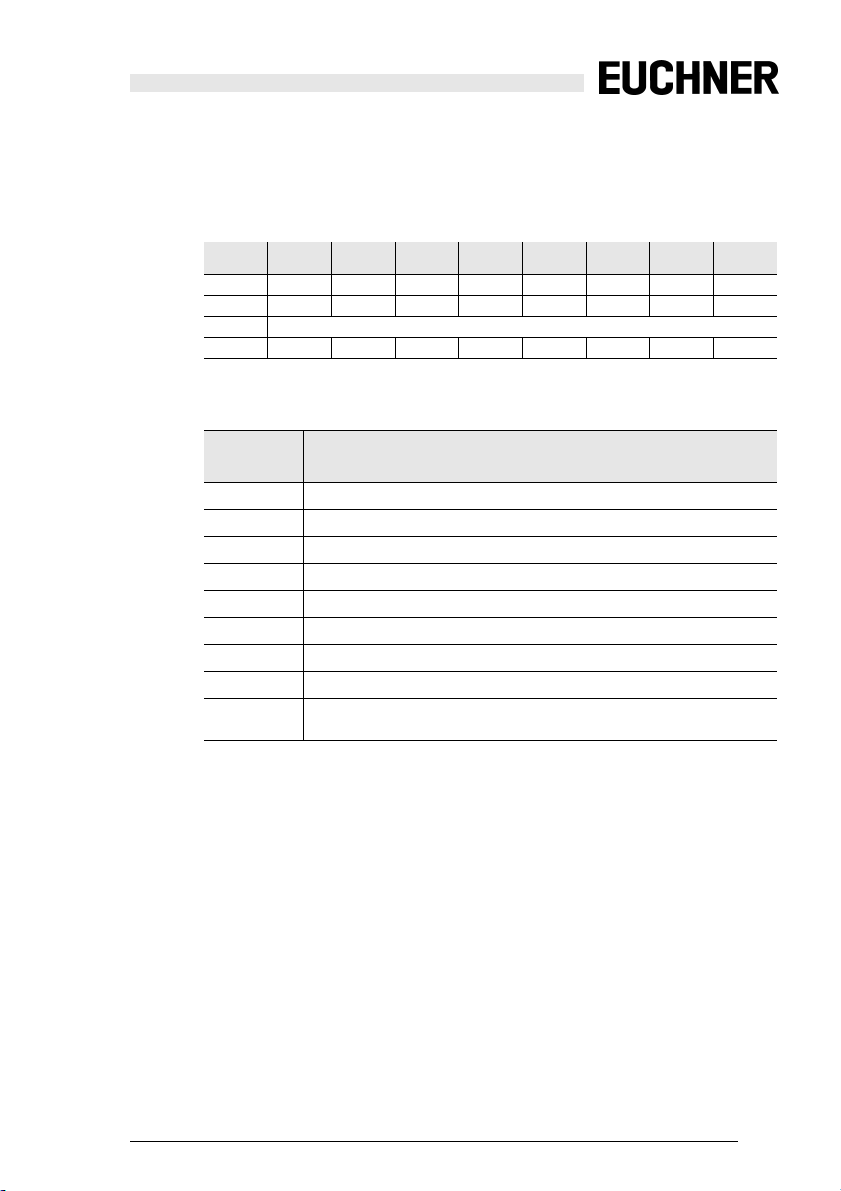
6.4.3.5 Vendor specific object 11 … 38
Objects 11 … 38 correspond to Objects 7 … 10, but do not refer to the following
release circuits. The table shows the relationship:
OSSD device
colors
device colors with
device index
device col-
ors at switch
off
device colors at
switch off mit
device index
Vorverarb. object 3 object 4 - -
1 object 7 object 8 object 9 object 10
2 object 11 object 12 object 13 object 14
3 object 15 object 16 object 17 object 18
4 object 19 object 20 object 21 object 22
5 object 23 object 24 object 25 object 26
6 object 27 object 28 object 29 object 30
7 object 31 object 32 object 33 object 34
8 object 35 object 36 object 37 object 38
9 object 39 object 40 object 41 object 42
10 object 43 object 44 object 45 object 46
11 object 47 object 48 object 49 object 50
12 object 51 object 52 object 53 object 54
13 object 55 object 56 object 57 object 58
14 object 59 object 60 object 61 object 62
15 object 63 object 64 object 65 object 66
16 object 67 object 68 object 69 object 70
Tab. 6-36.
Subject to reasonable modifications due to technical advances Id.-No.: 114013 Issue date: 14.11.2011 EUCHNER GmbH + Co. KG
38
Kohlhammerstraße 16, D-70771 Leinfelden-Echterdingen Tel. +49/711/7597-0, Fax +49/711/753316
Page 39

Safety Basic Monitor
AS-i Diagnostics
6.4.3.6 Vendor- specific object 110
Vendor specific object 110 describes the SaW slave diagnostics.
^
15 14 13 12 11 10 9 8 7 6 5 4 3 2 1 0
Slv 7 Slv 6 Slv 5 Slv 4 Slv 3 Slv 2 Slv 1
CH1
Slv 15 Slv 14 Slv 13 Slv 12 Slv 11 Slv 10 Slv 9 Slv 8
CH2
Slv 23 Slv 22 Slv 21 Slv 20 Slv 19 Slv 18 Slv 17 Slv 16
CH3
Slv 31 Slv 30 Slv 29 Slv 28 Slv 27 Slv 26 Slv 25 Slv 24
CH4
For each safe slave (ID=B) the status of the code sequence is entered as seen by
the Master. Code sequence errors are not detected here. For non-safe slaves ‘00’
is entered.
Bit-combination meaning
00 Not a safe slave or save slave with zero sequence, both switches
open
01 Safe slave, switch for upper bits open
10 Safe slave, switch for lower bits open
11 Safe slave, both switches closed
Information!
Please note additional informat ion in the manual for the ASIMON software.
Tab. 6-37.
Tab. 6-38.
Subject to reasonable modifications due to technical advances Id.-No.: 114013 Issue date: 14.11.2011 EUCHNER GmbH + Co. KG
Kohlhammerstraße 16, D-70771 Leinfelden-Echterdingen Tel. +49/711/7597-0, Fax +49/711/753316
39
Page 40

Safety Basic Monitor
Configuration of the safe inputs
7. Configuration of the safe inputs
The unit is configured and diagnosed using the ASIMON software.
Communication takes place over the USB interface.
7.1 Configuration possibilities for the safe inputs
The safe inputs on the unit can be configured variously:
• Safe inputs for floating contacts
Two inputs act together on one sub-device which can serve as the source for
a safety device. Test pulses are used to check the inputs for cross-wire short.
• Safe inputs for self-testing OSSDs (only on contacts S5-S8).
Two inputs act together on one sub-device which can serve as the source for
a safety device. The unit does not check the inputs for cross-wire short, since
this is done by the OSSDs themselves.
• Standard inputs
.
Each channel operates independently. The values can be used like the familiar monitor inputs.
• Diagnostics outputs
.
The test pulse outputs of the input terminals (i.e. terminals S11, S22, S31,
S42, S51, S62, S71, S82) can be used as diagnostics outputs (approx. 10mA
max. output current). A safety device can be assigned to each input, where
the status of the device is represented on the diagnostics output. The diagnostics output turns on when the device is “green”.
Configuration is done in ASIMON, in the ‘Monitor/Bus Information’ window using
the ‘Safety Basis Monitor’ tab.
.
The ASIMON Control logic prevents invalid combinations.
Subject to reasonable modifications due to technical advances Id.-No.: 114013 Issue date: 14.11.2011 EUCHNER GmbH + Co. KG
40
Kohlhammerstraße 16, D-70771 Leinfelden-Echterdingen Tel. +49/711/7597-0, Fax +49/711/753316
Page 41

Safety Basic Monitor
Configuration of the safe inputs
Safety Input Dry Contacts Safety Input OSSD Std Input Diag Out
S1
S2
S3
√
S4
S5
S6
S7
√
S8
7.2 Assigning the diagnostics outputs
Diagnostics outputs represent the status of the selected safety devices. Outputs
are assigned using the ‘Diagnostics Output’ column in the ‘Module Index Assignment’ field.
√√
√√
√
Tab. 7-39.
There the selected diagnostics outputs can be assigned to the module indices.
Each diagnostics output can be assigned to just one safety device.
Subject to reasonable modifications due to technical advances Id.-No.: 114013 Issue date: 14.11.2011 EUCHNER GmbH + Co. KG
Kohlhammerstraße 16, D-70771 Leinfelden-Echterdingen Tel. +49/711/7597-0, Fax +49/711/753316
41
Page 42
Safety Basic Monitor
Configuration of the safe inputs
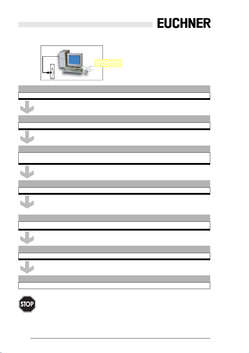
7.3 Safe configuration using ASIMON 3 G2
ASIMON
USB
ASIMON 3 G2 Software
Change the preset password during the first use of the device (Monitor/change password)!
ASIMON 3 G2 Software
Create the desired configuration.
ASIMON 3 G2 Software
Download the configuration with MONITOR / PC-> MONITOR into the device. Enter the password for
this purpose.
ASIMON 3 G2 Software
Acknowledge the request TEACH CODE SEQUENCES? selecting "Yes".
Start
ASIMON 3 G2 Software
Check the configuration log (respect instructions in <chap. 5.8> of the ASIMON manual!).
ASIMON 3 G2 Software
Validate the configuration with MONITOR –> VALIDATION.
ASIMON 3 G2 Software
Start the monitor with MONITOR–> START.
The correct safety function of the device must be verified once installed within the protected machinery!
Subject to reasonable modifications due to technical advances Id.-No.: 114013 Issue date: 14.11.2011 EUCHNER GmbH + Co. KG
42
Kohlhammerstraße 16, D-70771 Leinfelden-Echterdingen Tel. +49/711/7597-0, Fax +49/711/753316
Page 43

Safety Basic Monitor
Configuration of the safe inputs
7.3.1 Replacing a defective AS-i Safety Slave
[1]
Safety In
Adr. 2
[2]
alt
[3]
AS-i network
AS-i network
Safety
Basic Device
Power
Supply
Safety
Basic Device
Power
Supply
Safety In
Adr. 1
Safety In
Adr. 2
Safety In
Adr. 1
neu*
Analog Out
Adr. 6
Analog Out
Adr. 5
Analog Out
Adr. 6
Analog Out
Adr. 5
Safety Output
Module
Slave
Adr. 9/8a
Safety Output
Module
Slave
Adr. 9/8a
[4] [5]
Safety
Basic Device
AS-i network
Power
Supply
* ’new’ (address ’0’ or ’2’)
Safety In
Adr. 2
Safety In
Adr. 1
Analog Out
Adr. 6
Analog Out
Adr. 5
Safety Output
Module
Slave
Adr. 9/8a
SET
> 1s
SET
> 1s
Subject to reasonable modifications due to technical advances Id.-No.: 114013 Issue date: 14.11.2011 EUCHNER GmbH + Co. KG
Kohlhammerstraße 16, D-70771 Leinfelden-Echterdingen Tel. +49/711/7597-0, Fax +49/711/753316
43
Page 44

Safety Basic Monitor
Configuration of the safe inputs
7.3.2 Auto-addressing
[1]
Safety
Basic Device
AS-i network
Power
Supply
[2]
Safety
Basic Device
AS-i network
Power
Supply
* ’new’ (address ’0’ or ’2’)
alt
Analog In
Adr. 2
Safety In
Adr. 1
Analog In
Adr. 2
Safety In
Adr. 1
Analog In
Adr. 2
neu*
Analog Out
Adr. 6
Analog Out
Adr. 5
Analog Out
Adr. 6
Analog Out
Adr. 5
Safety Output
Module
Slave
Adr. 9/8a
Safety Output
Module
Slave
Adr. 9/8a
Subject to reasonable modifications due to technical advances Id.-No.: 114013 Issue date: 14.11.2011 EUCHNER GmbH + Co. KG
44
Kohlhammerstraße 16, D-70771 Leinfelden-Echterdingen Tel. +49/711/7597-0, Fax +49/711/753316
Page 45

Safety Basic Monitor
Safety Requirements
8. Safety Requirements
8.1 Safety consideration for selecting OSSD/potential-free contacts
Potential-free contacts are cross-circuit monitored by the module. OSSD outputs
test themselves and only require that the module tolerate the test pulses.
If the module is incorrectly configured so that OSSDs are connected but potentialfree contacts are configured, a cross-circuit is detected, since the test pulses
which the module sends out on S82 and S62 do not correlate with the test pulses
on S81 and S61. The error is thus detected.
If the module is incorrect configured so that potential-free contacts are connected
by OSSDs are configured, Contact S81 / S82 is never seen as turned on, since
S82 is not turned on as a supply pin for the OSSD module. The error is thus detected. The same applies by analogy to Contact S61 / S62.
8.2 Recommendation for improved availability of the function
The switching contacts should be turned off for at least 41 ms, since the safety
monitor (depending on the set monitoring component) must recognize the INPUT
OFF for a minimum number of AS-i telegrams. IF the minimum off time of 41 ms
(depending on the number of slaves on the AS-i bus and the set monitoring component) is maintained, correct recognition of the input state is assured. Non-observance of this time may limit the availability of the AS-i Safety Monitor as follows:
• A setting of TWO-CHANNEL POSITIVE OPENING can cause the Safety
Monitor to go into the error state; to eliminate the error state, the supply voltage for the Safety Monitor must be disconnected.
• A setting of TWO-CHANNEL DEPENDENT means the Safety Monitor allows
release only after a sufficient off-time; the release can be achieved if the
switching contacts are turned off for at least 41 ms .
Subject to reasonable modifications due to technical advances Id.-No.: 114013 Issue date: 14.11.2011 EUCHNER GmbH + Co. KG
Kohlhammerstraße 16, D-70771 Leinfelden-Echterdingen Tel. +49/711/7597-0, Fax +49/711/753316
45
Page 46

Safety Basic Monitor
Accessories
9. Accessories
• SBM-ZB-PGK (Ident-Nr. 113832)
USB connector cable for Safety Basic Monitor
• ZMO-ZB-MB10 (Ident-Nr. 100875)
Chip card for GMOX/SMOX 32kByte
• ESM-F-KK4 (Ident-Nr. 097195)
Connecting kit ESM-F (Phoenix clamps 4 unit)
Subject to reasonable modifications due to technical advances Id.-No.: 114013 Issue date: 14.11.2011 EUCHNER GmbH + Co. KG
46
Kohlhammerstraße 16, D-70771 Leinfelden-Echterdingen Tel. +49/711/7597-0, Fax +49/711/753316
 Loading...