

Page 1
Operating Instructions for Rope Pull Switches
RPS...
Safety rope pull switch RPS
Correct use
In accordance with EN 60947-5-5, EN ISO 13850, it must be ensured that parts of or complete industrial
machines or installations can be stopped as quickly as possible by generation of an emergency stop signal.
The purpose of these regulations is to prevent any danger for persons or damage to machines.
The following applicable standards must be taken into account for this purpose:
Regulations on installation and operation: EN ISO 13849-1 Safety of machinery. Safety related parts of
control systems
Risk assessment on the machine: EN ISO 12100, Safety of machinery – Basic concepts –
General principles for design – Risk assessment and risk
reduction.
The safety rope pull switches of the series RPS have been designed and tested in accordance with the
standards EN 60947-5-5 and EN ISO 13850. They must be used only in control circuits.
Safety rope pull switches are used on the accessible sides of conveyor systems or machines. In contrast to
emergency stop switches (e.g. mushroom-head pushbuttons) located at certain intervals that allow the
emergency stop signal to be generated only at the devices themselves, rope pull switches allow signal
generation at any point along the rope length.
The safety rope pull switches of the type RPS are intended for use only in closed areas.
Design
The safety rope pull switches of the type RPS consist of a polyamide housing, those of the type RPS-M of a
die-cast aluminum housing. They achieve the specified degree of protection IP67 if the cover is properly closed
and if a cable gland is used that offers at least equivalent protection. The RPS has three cable entries M20x1.5.
The switches comply with the international requirements according to EN 60947-5-5 and EN ISO 13850, i.e.
after actuation or a rope tear, the emergency stop switch latches automatically, and the switch can then be
reset to its initial state only by means of the resetting device on the switch.
Depending on the switch version, it is possible to achieve a rope length of 75 m. It must be taken into account
here that the friction in the overall system can become so high due to the rope guides that this makes it difficult
or impossible to reset the system (see section Installation).
This can be avoided by choosing different system components.
The user is responsible for ensuring that the system functions properly.
Page 2
Operating Instructions for Rope Pull Switches
RPS...
Function
The system consists of the switching device, a red pull rope, supports and a counterspring.
The pull device of the rope pull switch is connected with a pull rope. The emergency stop function can be
tripped by pulling this rope. Since the rope pull system is pretensioned by an integrated spring, switch latching
and the emergency stop function are tripped immediately if the rope tears. The safety contacts remain latched
after tripping. After the hazardous situation has been remedied and after examination of the entire pull rope
length, the system may be reset to operationally ready state again by manual operation of the reset button.
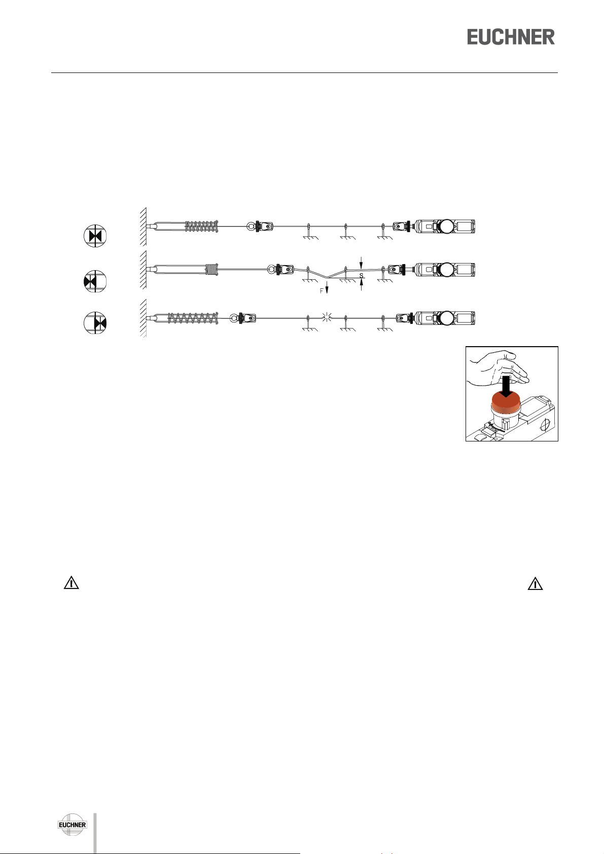
System operating
position
Triggering/
latching
Rope tear
“RESET”
by the operator
“STOP” triggering
by operator/
automatic latching
“STOP” triggering
automatic
latching automatic
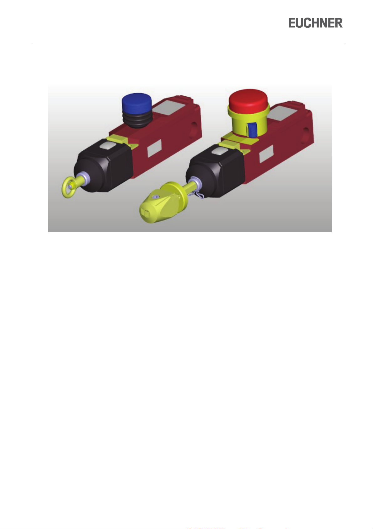
RPS...S
The RPS...SC... switch types have an integrated red emergency stop slam button that
can be actuated by pressing it if a hazardous situation occurs. Analogously to operation
of the pull rope, the safety contacts are then opened and the switch is latched. After
rectification of the hazardous situation, the system can be reset manually to operationally
ready state by turning the actuating cylinder 90° in clockwise direction.
Please also refer to item 3 of the section Installation sequence!
RPS...P
After remedying the dangerous situation and with the rope system tensioned, the rope pull switch
can be unlocked and so made operational again by turning the Reset knob.
Pre-failure monitoring (optional)
The safety rope pull switches of the type RPS-M-E-…have a remote display for monitoring the rope tension. It
uses an integrated sensor unit to monitor the permissible rope tension for being exceeded and impending
triggering of the safety rope pull switch.
Required maintenance/adjustment is signaled via an electronic output in good time before unintentional
machine standstills occur. Optionally available signal lamps can also be connected to this output; refer to the
section “Accessories”. This meets the requirements for “preventive maintenance”.
Safety precautions
All system components must be mounted on surfaces that can reliably withstand all the forces that may
occur.
Routing of the rope as straight as possible results in low frictional forces in the system. From a rope length
of 25 m, only rope pulley blocks may be used as rope supports.
Rope pulley blocks and other accessories are optionally available.
Positioning of the support points at irregular intervals prevents rope oscillations that might cause false
tripping.
The red pull rope must have sufficient space between the support points to ensure that secure gripping and
tripping are possible. To improve visibility, marking flags can be attached to the pull rope along its length;
however, these must not interfere with tripping of the emergency stop function!
When a pull rope section is being set up and planned, it is necessary to take into account and comply with
the applicable regulations, as well as the maximum permitted actuating travel of S= 400 mm and maximum
tripping force of F=200 N applied perpendicularly to the rope.
Suitable guide rollers must be used for rope routing at angles.
2
Page 3
Operating Instructions for Rope Pull
Switches RPS...
Improper installation or manipulation of the rope pull switch will lead to loss of the personal protection
function and can cause serious or fatal injuries.
Safety rope pull switches must not be bypassed (bridging of contacts), turned away, removed or otherwise
rendered ineffective.
The switching procedure may be triggered only by a pretensioned rope system when it is pulled or the rope
is severed.
If damage or wear is found, the complete switch must be replaced. Replacement of individual parts or
assemblies is not permitted!
Identification of the safety pull rope switch
Identification by designation
RPS-M-E-3131-SC-300M...
RPS safety rope pull switch (switch series)
- without
E pre-failure monitoring
- plastic housing
M metal housing
3131 switching function depends on the type used (standard 3131); see section
Switching elements
R with ring
C quick fastener and fast-action tensioning device
P without emergency stop pushbutton, reset by pull knob
S emergency stop pushbutton, reset by rotary actuating cylinder
e.g. 300 N max. spring force to tension the rope
Identification by item number
The item number of the switch is located beneath the switch designation on the switch label. Please state this
number in correspondence and orders to EUCHNER GmbH & Co. KG.
RPS3131SC300M
088884
...
...
...
3
Page 4
Operating Instructions for Rope Pull Switches
RPS...
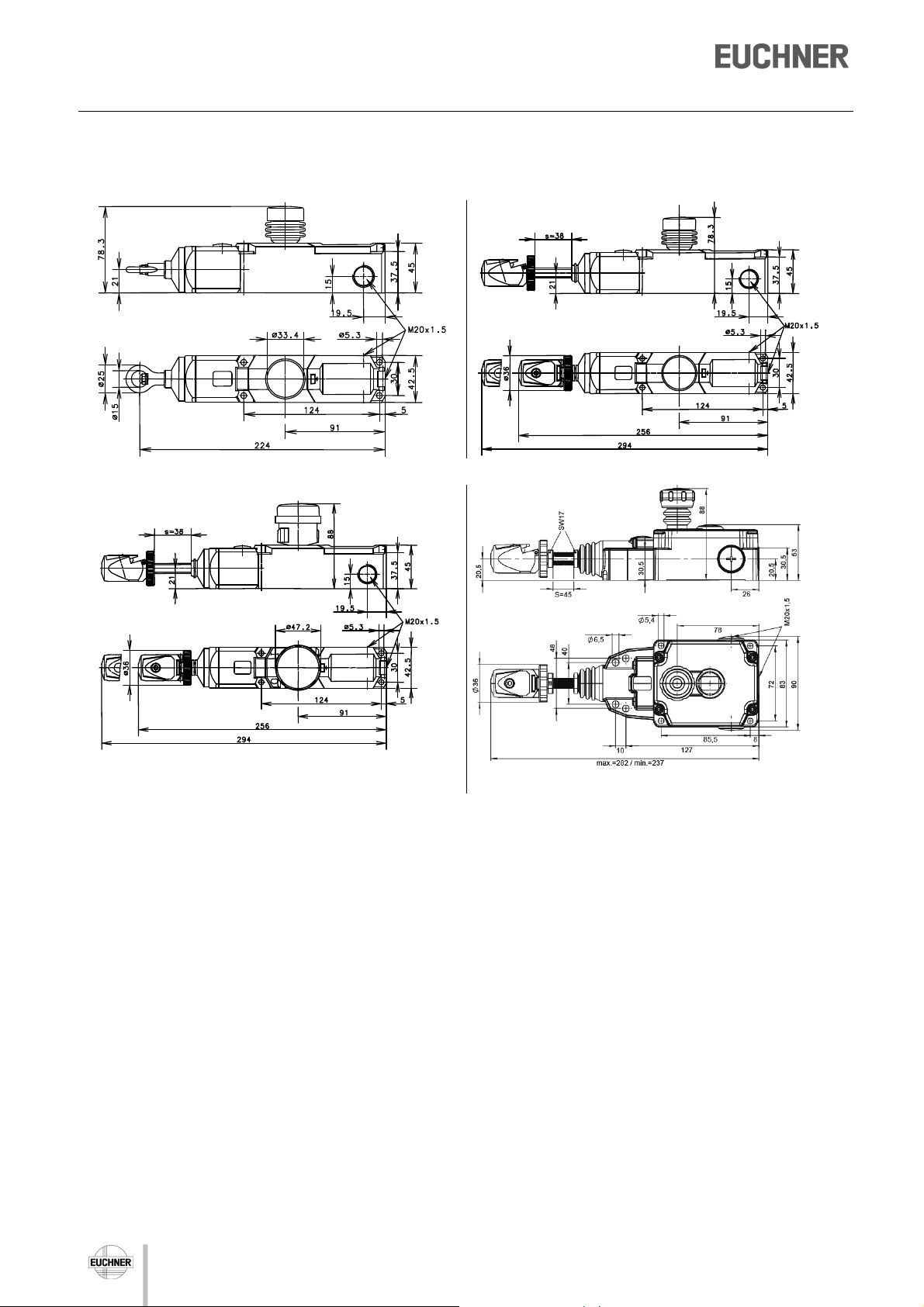
Dimensions
RPS...PR... RPS...PC...
RPS...SC... RPS-M...SC...
All dimensions in millimeters
4
Page 5
Operating Instructions for Rope Pull
Switches RPS...
Mounting
Note
Under ideal installation conditions it is possible to achieve a maximum rope tension length of 75 m.
Depending on the actual situation, there may be increased friction in the system. This friction may be so high
that automatic resetting is no longer possible as described above. However, tripping in the event of a rope tear
must be guaranteed in all cases.
The amount of friction depends on:
- Number of eyebolts used
- Number of contact angles and deflections
- Number and size of guide rollers
- Alignment of rollers and eyebolts with respect to each other.
The friction can be reduced by using guide rollers with a larger diameter. The system should be divided up if
there is too much friction. The user is responsible for component selection and correct functioning of the
system.
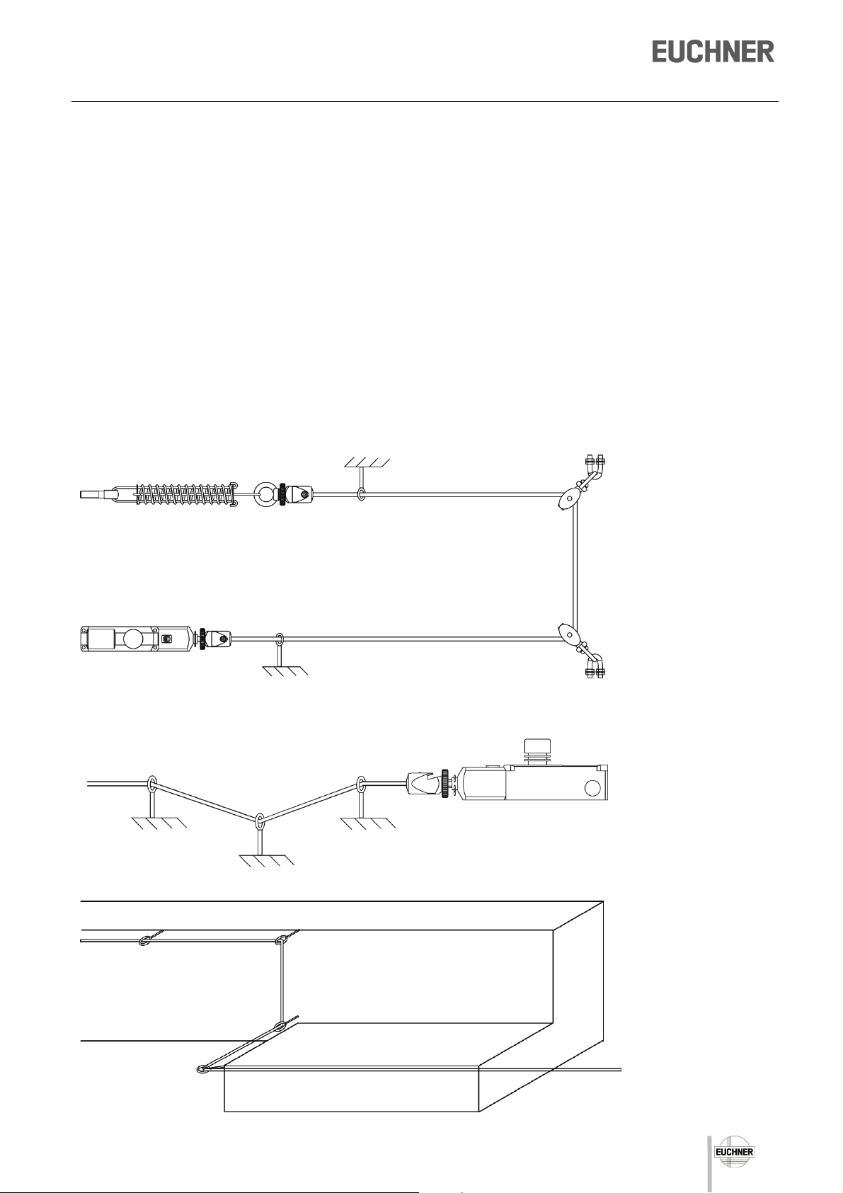
Example of proper installation
Example of improper installation
5
Page 6

Operating Instructions for Rope Pull Switches
RPS...
Selection of system components
A tensioner spring must be installed on the thrust bearing in order to ensure proper and safety-compliant
implementation of the pull rope system. This is a precondition for direction-independent tripping at any point
along the rope length. In order to achieve fast and simple compliance with this requirement, we recommend the
use of EUCHNER tensioner springs with integrated overstretch protection (see Table 1). Additional fixing and
installation materials as well as ropes are also optionally available. A detailed overview is provided in the
section Accessories.
Tensioner spring
Table 1
RPS type RPS...100/175 RPS...300
Item number 092136 092138
L
[mm] 383 483
0 min.
L
[mm] 487 653
max.
ØD [mm] 39 48
Tensioner springs are supplied with quick fastener and an eyebolt DIN 444 - M12 x 50
6
Page 7

Operating Instructions for Rope Pull
Switches RPS...
When installing and adjusting the rope pull switch, it is necessary to take into account the physical changes in
the rope length as a result of variations in temperature.
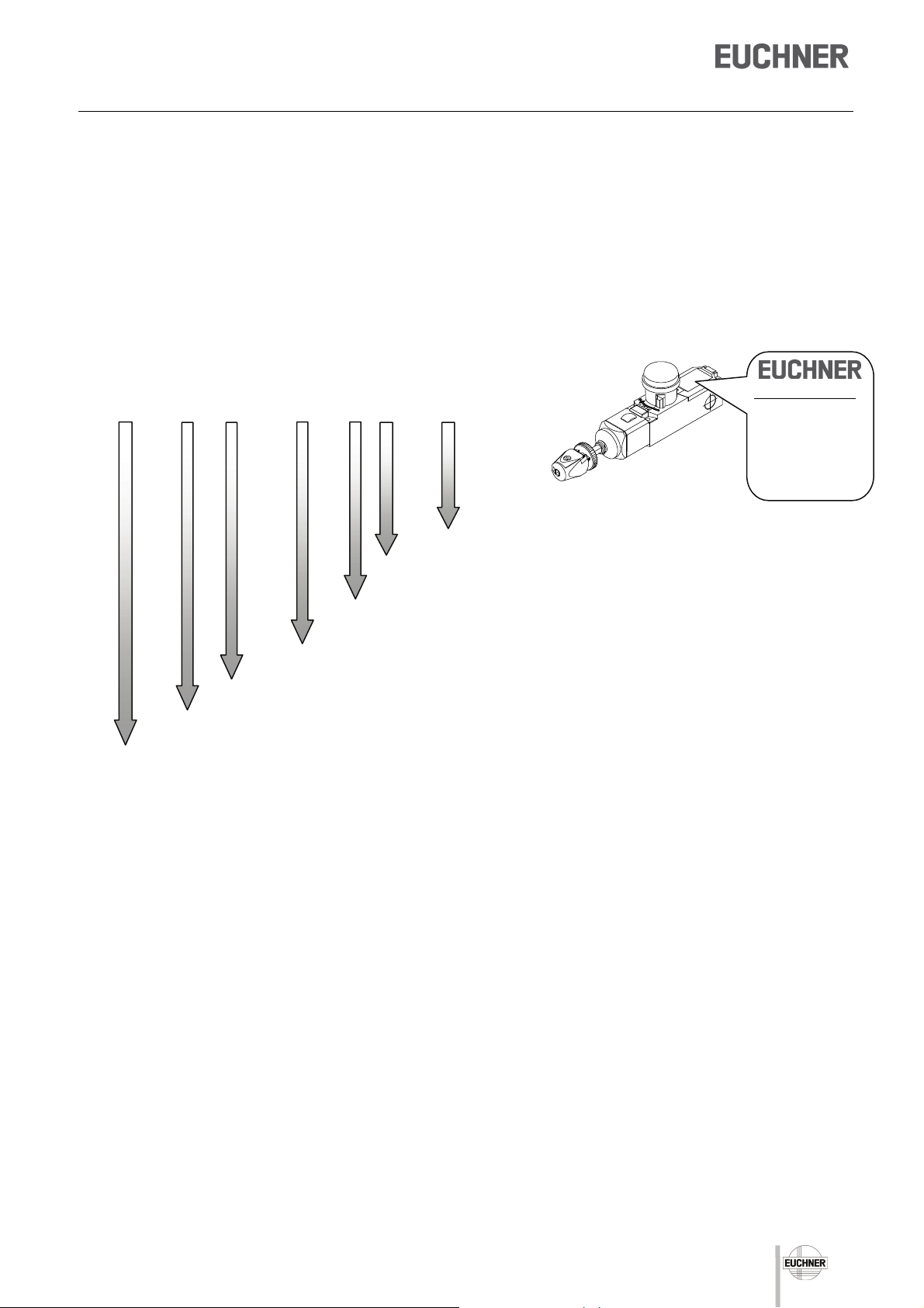
Table 3 shows the permitted rope tension lengths as a function of the expected temperature difference.
The diagram also shows the maximum permitted rope tension length for the different spring forces of the
respective switch types. It also permits selection of the appropriate switch corresponding to the expected
temperature variations.
Table 3
Max. temperature
RPS...100 Rope tension length max. 25 m
RPS...175 Rope tension length max. 37.5 m
RPS...300 Rope tension length max. 75 m
1 2 3 4 5 6 7 8 9
+/-40 K
+/-35 K
+/-30 K
Kelvin
fluctuation in
+/-25 K
+/-20 K
10
11
+/-15 K
+/-10 K
Rope tension length Lmax. in meters [m]
12
13
14
15
16
17
18
19
20
22
24
26
28
30
32
34
36
38
40
42
44
46
48
50
55
+/-5 K
+/-3.5 K
60
65
Rope supports must be provided at intervals of 2–5 m when planning and installing the system. Refer also to
the section Safety precautions.
70
75
7
Page 8

Operating Instructions for Rope Pull Switches
RPS...
Installation sequence
Installation must be performed only by authorized personnel.
1
A
1.1A
1.2A
Attach bearing element with tensioner spring; fit pull rope: sheathing must be removed in clamping area; insert rope
in the fast-action clamping head as shown and secure.
B
Attach bearing element with counterspring; fit pull rope: secure rope as shown with thimble and rope clamp, attach
rope bridge to limit travel of counterspring with thimbles and rope clamps.
2
1.1B
1.2B
1.3A
2 - 5 m La = 150 mm
rope tension
Observe distance to the 1st support point. The 1st rope support next to the switch must be installed after La =150
mm.
Install supports at intervals of 2 – 5 m.
Fasten the RPS switch with four M5 screws
3
(also M6 for RPS-M) .
Maximum tightening torque M = 2 Nm.
Display
The emergency stop switches must be
positioned so that the rope or emergency stop
slam button can be reached without obstacles
in hazardous situations.
17
Display
48
40
10
85,5
72
8
Page 9

Operating Instructions for Rope Pull
Switches RPS...
A
4
Connect pull rope fast-action clamping head (see Item 1).
Pre-tension pull rope.
B
Connect pull rope with turnbuckle as shown (3x rope clamp with thimble)
Basic setting should take place at a temperature corresponding to the prevailing operating conditions.
5
The length of the pull rope changes if there is a large change in the ambient temperature. Under these conditions,
long rope lengths mean a frequent change in the basic setting.
This can be remedied by re-adjustment (Item 5) or shortening the rope length (Table 3).
A
Adjust the setting ring until the arrow tips of the
display are aligned with the marking.
Hold the fast-action clamping head tight when
doing this to prevent the pull rope from twisting
Display:
B
Adjust the turnbuckle until the arrow tips of the display are flush with the marking.
Mechanical function test
RPS...PR/PC
A
6
Pull up the blue RESET knob:
- safety contacts closed.
Actuate the pull rope:
- safety contacts open.
S max. 400 mm
max. 200 N
RPS...SC...
B
Turn yellow actuating cylinder at the
RESET contact areas (blue) by 90° up
to the marking, then release.
Cylinder returns to initial position.
Operate the EMERGENCY STOP
button or the pull rope for each test
procedure.
S max. 400 mm
Display:
max. 200 N
Operate the pull rope forcefully several times in order to settle the pull rope section.
If necessary, carry out re-adjustment by means of the adjusting screw/turnbuckle.
9
Page 10

Operating Instructions for Rope Pull Switches
RPS...
Electrical connection
Electrical connection must be performed only by authorized personnel.
Connection of RPS…
1. Release cover using a screwdriver
2. Open break-out wall by screwing in the cable
gland, remove the plastic part
3. Tighten cable gland
4. Connection to cage pull spring
5. Insert screwdriver (2.5 mm blade width) (1) into
bottom opening
6. Turn screwdriver by 45 (2)
7. Insert flexible cable with a cross-section of 0.08 ...
1.5 mm² in the upper opening (3)
The cable end must be fitted with a wire end
ferrule.
8. Remove screwdriver
9. Press on cover
Connection of RPS-M…
1. Remove cover. To do this, unscrew the cover
screws with a screwdriver and remove the cover.
2. Electrical connection. The electrical contacts of
the switches have M3.5 screw terminals. For the
terminal assignment, see section “Circuit symbol
and switching diagram”.
The connection must be made as stranded wire
with wire end ferrule or as a single wire with the
conductor cross sections 0.5 … 1.5 mm².
3. Close cover. Place the cover on the housing as
shown and tighten the cover screws with a
torque of 2 Nm.
10
Page 11

Operating Instructions for Rope Pull
Switches RPS...
Connection example
The following connection example shows a possible circuit structure with redundant design at the cable level as
well.
The signals of the emergency stop chain are evaluated by a safety relay (ESM from EUCHNER).
The overall control concept into which the pull rope switch RPS is integrated must be evaluated by the end
consumer/machine designer in accordance with EN ISO 13849-2.
24V
RPS
S3
S2
S1
K1
A1A2S11
24VDC
21
22
ESM-BA301
S10
S13
41
42
EUCHNER
EUCHNER
131433
RPS3131SC....
34
23
24
23
24
21
K1B
22
23
21
K1A
24
22
S21
S12 S14 13142324333441
+
K1
+
K2
42
A1
K1A K1B
A2
24V
A1
A2
PE
GND
21 22 .2 21 22 .2
Setup
Mechanical function test
It must be possible to actuate the pull rope easily at every point of the cabling rope pull system. As a check,
actuate the pull rope several times.
Electrical function test
Activate the rope pull system by means of the RESET actuating cylinder.
Start the installation/machine.
Actuate the pull rope / EMERGENCY STOP button: this results in the safety contacts opening immediately.
The safety contacts close only after renewed operation of the RESET actuating cylinder.
GND
11
Page 12

Operating Instructions for Rope Pull Switches
App
g
App
g
RPS...
Technical data
Version RPS… RPS-M…
Electrical data (refers to the switch without plug connector)
Rated insulation voltage Ui 250 V
Rated operating voltage Ue 240 V
Rated impulse withstand voltage U
Continuous thermal current I
Utilization category AC 15; 230 V/ 3 A AC 15; 240 V/ 3 A
Short circuit protection 6 A gG acc. to IEC 60269-1
Safety class II I
Positively driven NC contacts
Pre-failure monitoring RPS-M-E…
Rated operating voltage Ue 10-30 V/DC
Rated operating current Ie 50 mA
Utilization category DC 13
Short circuit protection Yes
Reverse polarity protection Yes
Connection Screw terminal, 3-pin
Mechanical data
Housing/cover PA 6 GV (UL94-VO) die-cast aluminum
Emergency stop PA, glass-fiber reinforced
Actuation Die-cast zinc/steel
Ambient temperature -25°C to +70°C -30°C to +80°C
Contact opening gap > 2 x 2 mm
Mechanical life acc. to IEC 60947-5-5 1 x 10⁵ operating cycles
Switching frequency ≤ 20/min.
Latching device acc. to EN 60947-5-5, DIN EN 418
Emergency stop reset RPS...SC : By turning the RESET actuating cylinder
RPS...PR/PC: By pulling the blue RESET button
Rope length acc. to type L
Rope D = 2 - 5 mm
Rope attachment
Connection
Cable entry 3 x M20x1.5
Mounting 4 x M5 4 x M5 or 4 x M6
Weight
Degree of protection IP67 acc. to EN 60529
Regulations
EC conformity
Approvals
2.5 kV
imp
10 A
the
DC 13; 250 V/ 0.27 A
IEC/ EN 60947-5-1, Appendix K
= 1.5 mm²
= 75 m / 37.5 m / 25 m (observe Table 3)
max
RPS...SC/PC... Fast-action clamping device / PR... by
means of ring
8 x x cage pull springs 0.08
... 1.5 mm² flex.
rox. 0.65 k
EN 60947-1, EN 60947-5-1, EN 60947-5-5, EN ISO 13850
See enclosed Declaration of Conformity
c CSA us / BG
8 screw terminals (М3.5)
rox. 1.0 k
12
Page 13

Operating Instructions for Rope Pull
Switches RPS...
Switching elements
The values for the tensile force depend on the switch type used. (RPS...100/RPS...175/RPS...300)
Tolerance: tensile force ± 15%
3131 (standard) 2131
Detent
Detent
3131 RPS-M (optionally with pre-failure monitoring)
S1
Detent
Detent
S2
ON OFF
Maintenance/service
In order to ensure trouble-free, long-term operation, it is necessary to perform regular, documented inspection
of the following:
- smooth actuation
- correct switching function
- Correct rope tension
- secure mounting of components
- dirt and wear
- sealing of cable entry
- loose cable connections or plug connectors.
After servicing or repair, correct functioning of the system should be checked by actuating the pull rope several
times. It must be ensured that the switch latches properly after actuation.
In the event of a fault in the switching system or latching device, the switch must be replaced and can be sent
to EUCHNER GmbH + Co. KG for inspection.
Exclusion of liability
If the instructions (incorrect use, safety regulations, mounting and connection by trained personnel, check for
safe function) are violated, this renders the manufacturer’s liability null and void.
13
Page 14

Operating Instructions for Rope Pull Switches
RPS...
Accessories
Designation Description/version
Eyebolt
Rope set
RPS roller set
Tensioning rope
Built-in LED
Turnbuckle
Tensioner spring
Thread M8
Consisting of thimble and rope clamp
Rope pulley block with swiveling lug (roller Ø 6 mm) and fastening clamp
Rope pulley block (roller Ø 14 mm) and fastening clamp
Length 50 m
Length 100 m
Light radiation to side
Light radiation to front
M6 x 60
M6 x 110
for RPS 100, 175
for RPS 300
Packaging
unit
5 ea.
5 ea.
5 ea.
1 ea.
1 ea.
1 ea.
1 ea.
1 ea.
5 ea.
1 ea.
1 ea.
1 ea.
Order no./item
092495
092496
092501
096251
RPS-P/V1
092813
092814
087423
095510
092498
092500
092136
092138
RPS-O-8-50/V5
RPS-RS/V5
RPS-PS/V5
RPS-I-3-4/50M
RPS-I-3-4/100M
LED M20x1.5
LED M20x1.5
RPS-B-6-60/V5
RPS-B-6-110
RPS-W-100-175
RPS-W-300
14
Page 15

Operating Instructions for Rope Pull
Switches RPS...
15
Page 16

Euchner GmbH + Co. KG
Kohlhammerstraße 16
D-70771 Leinfelden-Echterdingen
info@euchner.de
www.euchner.de
Edition:
090276-06-08/12
Title: Operating Instructions for Rope Pull
Switches RPS
Copyright:
© EUCHNER GmbH + Co. KG, 08/2012
Subject to technical modifications;
no responsibility is accepted for the accuracy of
this information
0800000388
0800000606
 Loading...