

Page 1
Betriebsanleitung Sicherheitsschalter NX...
A
Öffnen
Bestimmungsgemäßer Gebrauch
Sicherheitsschalter der Baureihe NX sind Verriegelungseinrichtungen ohne Zuhaltung.
In Verbindung mit einer trennenden Schutzeinrichtung verhindert dieses Sicherheitsbauteil, dass
gefährliche Maschinenbewegungen ausgeführt
werden, solange die Schutzeinrichtung geöffnet
ist. Wenn die Schutzeinrichtung während der gefährlichen Maschinenfunktion geöffnet wird, wird ein
Halt-Befehl ausgelöst.
Die Sicherheitsschalter der Baureihe NX entsprechen
den Vorschriften EN 60947-5-1 (inkl. Anhang K)
und erfüllen die Anforderungen der Berufsgenossenschaften für Maschinen, Anlagen und Personenschutz.
Vor dem Einsatz von Sicherheitsschaltern ist eine
Risikobeurteilung an der Maschine durchzuführen
nach
EN ISO 13849-1, Sicherheitsbezogene Teile von
Steuerungen
EN ISO 14121, Sicherheit von Maschinen, Risi-
kobeurteilung.
IEC 62061, Sicherheit von Maschinen - Funktionale
Sicherheit sicherheitsbezogener elektrischer, elektronischer und programmierbarer elektronischer
Steuerungssysteme.
Zum bestimmungsgemäßen Gebrauch gehört das
Einhalten der einschlägigen Anforderungen für den
Einbau und Betrieb, insbesondere
EN ISO 13849-1, Sicherheitsbezogene Teile von
Steuerungen
EN 1088, Verriegelungseinrichtungen in Verbin-
dung mit trennenden Schutzeinrichtungen
EN 60204-1, Elektrische Ausrüstung von Ma-
schinen.
Wichtig:
Der Anwender trägt die Verantwortung für die
sichere Einbindung des Geräts in ein sicheres
Gesamtsystem. Dazu muss das Gesamtsystem
z. B. nach EN ISO 13849-2 validiert werden.
Wird zur Validierung das vereinfachte Verfahren
nach Abschnitt 6.3 EN ISO 13849-1:2008 benutzt,
reduziert sich möglicherweise der Performance
Level (PL), wenn mehrere Geräte hintereinander
geschaltet werden.
Liegt dem Produkt ein Datenblatt bei, gelten die
Angaben des Datenblatts, falls diese von der
Betriebsanleitung abweichen.
Sicherheitshinweise
Sicherheitsschalter erfüllen eine PersonenschutzFunktion. Unsachgemäßer Einbau oder Manipulationen können zu schweren Verletzungen von
Personen führen.
Sicherheitsbauteile dürfen nicht umgangen
(Kontakte überbrückt), weggedreht, entfernt
oder auf andere Weise unwirksam gemacht
werden.
Beachten Sie hierzu insbesondere die Maßnahmen
zur Verringerung der Umgehungsmöglichkeiten
nach EN 1088:1995.A2:2008, Abschn. 5.7.
Der Schaltvorgang darf nur durch speziell dafür
vorgesehene Betätiger ausgelöst werden, die
unlösbar mit der Schutzeinrichtung verbunden
sind.
Montage, elektrischer Anschluss und Inbe-
triebnahme ausschließlich durch autorisiertes
Fachpersonal.
Funktion
Der Sicherheitsschalter meldet, dass die Schutzeinrichtung geschlossen ist.
Durch den Schalter erfolgt keine Zuhaltung!
Schließen
Durch Einführen des Betätigers werden die Sicherheitskontakte geschlossen.
Durch Herausziehen des Betätigers werden die
Sicherheitskontakte zwangsweise geöffnet.
Montage
Sicherheitsschalter und Betätiger dürfen nicht
als Anschlag verwendet werden.
Nur in zusammengebautem Zustand befesti-
gen!
Sicherheitsschalter so anbauen, dass
er für Bedienpersonal bei geöffneter Schutzein-
richtung schwer zugänglich ist.
Wartung und Austausch möglich ist.
Betätiger in Betätigungskopf einführen.
Sicherheitsschalter formschlüssig anbauen.
Betätiger dauerhaft und unlösbar mit der Schutz-
einrichtung verbinden, z.B. durch die beiliegenden
Einwegschrauben, nieten oder schweißen.
Zusätzlichen Anschlag für beweglichen Teil der
Schutzeinrichtung anbringen.
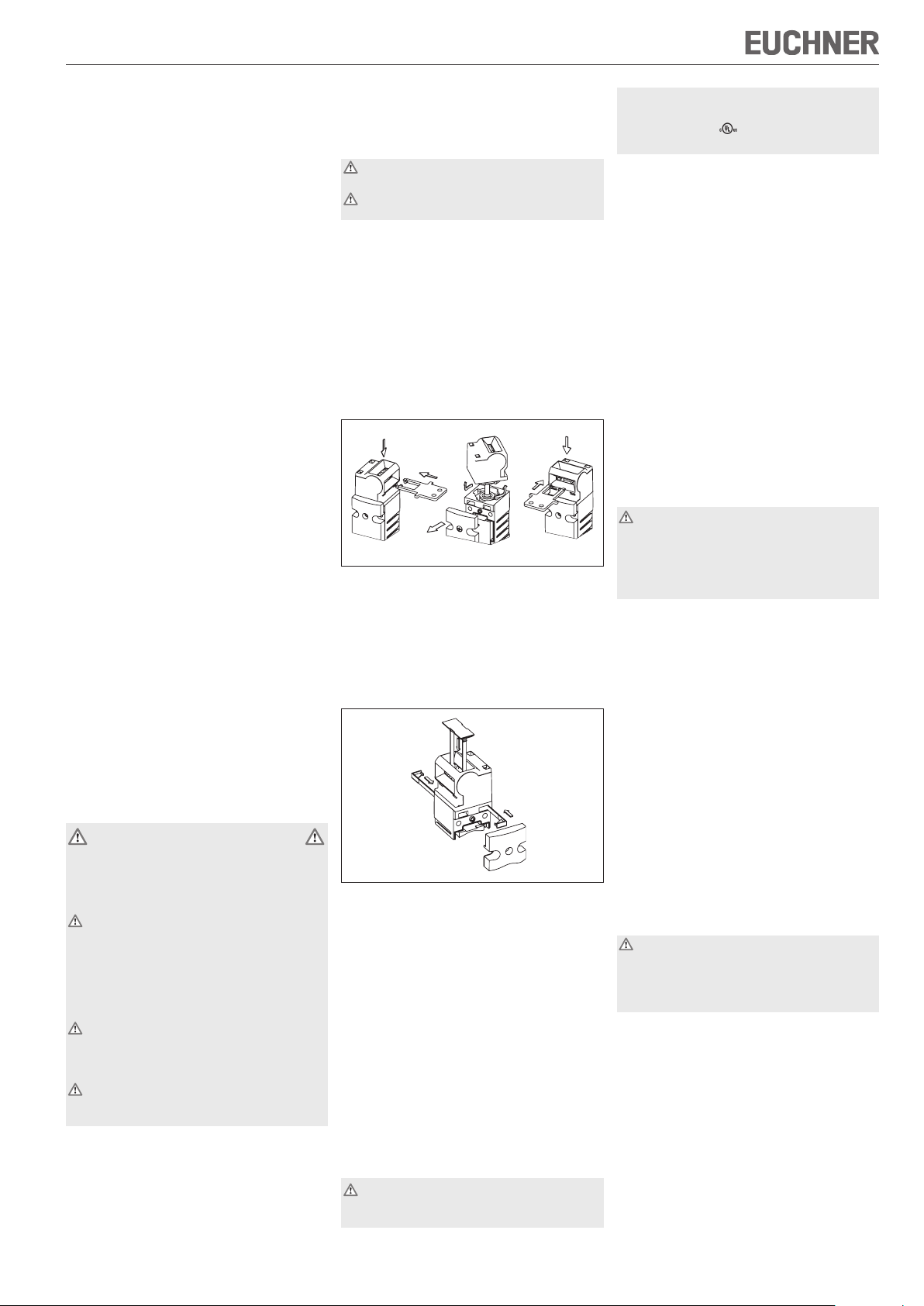
Umstellen der Betätigungsrichtung
Bild 1: Umstellen der Betätigungsrichtung
Schalterdeckel aufschrauben und öffnen.
Betätigungskopf durch Drehen vom Schalter
abnehmen und in gewünschter Position wieder
aufsetzen (Bajonettbefestigung).
Zum Verdrehschutz beiliegende Sicherungskeile
einsetzen (Bild 2). Ein weiteres Umstellen der Betätigungsrichtung ist dann nicht mehr möglich.
Bild 2: Einsetzen der Sicherungskeile und der
Schlitzabdeckung
Schalterdeckel schließen und verschrauben.
Nicht benutzten Betätigungsschlitz mit beiliegenden
Schlitzabdeckungen verschließen (Bild 2).
Schutz vor Umgebungseinflüssen
Voraussetzung für eine dauerhafte und einwandfreie
Sicherheitsfunktion ist der Schutz des Betätigungskopfes vor eindringenden Fremdkörpern wie Spänen,
Sand, Strahlmitteln usw.
Nicht benutzten Betätigungsschlitz mit Schlitzabdeckung verschließen.
Bei Lackierarbeiten den Betätigungsschlitz, den
Betätiger und das Typenschild abdecken!
Zur Reinigung der Schalter nur lösungsmittelfreie
Reinigungsmittel verwenden!
Elektrischer Anschluss
Bei der Auswahl von Isolationsmaterial bzw. An-
schlusslitzen, auf die Übertemperatur im Gehäuse
(abhängig von den Betriebsbedingungen) achten!
Für NX ohne Steckverbinder gilt:
Für den Einsatz und die Verwendung gemäß den
Anforderungen von ist Kupferleitung 60/75 °C
zu verwenden.
Ausführung NX1... (Leitungseinführung M20x1,5/
NPT ½" siehe Typenschild)
Verschlussschraube der gewünschten Einführöff-
nung herausdrehen.
Kabelverschraubung M20x1,5 bzw. NPT½" mon-
tieren.
Wichtig: Um die angegebene Schutzart zu erreichen
Kabelverschraubung von EUCHNER verwenden
(Best. Nr. 110 132, 110 133 oder 110 134).
Leiterquerschnitt von 0,34 mm² bis max. 1,5 mm².
Kontaktbelegung siehe Bild 3.
Klemmschrauben mit 0,6 Nm anziehen.
Auf Dichtheit der Leitungseinführung achten.
Schalterdeckel schließen und verschrauben.
Optionales LED-Modul L024
Max. anschließbarer Außendurchmesser 1,0 mm.
Kontaktbelegung siehe Bild 4.
Wegen des eingeschränkten Verdrahtungsraumes
möglichst dünne Litzen verwenden (Empfehlung
0,25 mm²)! Strombelastbarkeit der Litze beachten!
Funktionskontrolle
Warnung! Tödliche Verletzung durch Fehler bei
der Installation und Funktionskontrolle.
Stellen Sie vor der Funktionskontrolle sicher,
dass sich keine Personen im Gefahrenbereich
befinden. Beachten Sie die geltenden Vorschriften zur Unfallverhütung.
Nach der Installation und jedem Fehler muss eine
vollständige Kontrolle der Sicherheitsfunktion
durchgeführt werden. Gehen Sie dabei folgendermaßen vor:
Mechanische Funktionsprüfung
Der Betätiger muss sich leicht in den Betätigungskopf einführen lassen. Zur Überprüfung Schutzeinrichtung mehrmals schließen.
Elektrische Funktionsprüfung
1. Betriebsspannung einschalten.
2. Alle Schutzeinrichtungen schließen.
Die Maschine darf nicht selbständig anlaufen.
3. Betrieb in der Steuerung freigeben.
4. Schutzeinrichtung öffnen.
Die Maschine muss abschalten und darf sich nicht
starten lassen, solange die Schutzeinrichtung
geöffnet ist.
Wiederholen Sie die Schritte 2 - 4 für jede Schutzeinrichtung einzeln.
Kontrolle und Wartung
Bei Beschädigung oder Verschleiß muss der
gesamte Schalter mit Betätiger ausgetauscht
werden.
Der Austausch von Einzelteilen oder Baugrup
pen ist unzulässig!
Wartungsarbeiten sind nicht erforderlich. Um eine einwandfreie und dauerhafte Funktion zu gewährleisten,
sind regelmäßige Kontrollen erforderlich auf
einwandfreie Schaltfunktion
sichere Befestigung der Bauteile
Ablagerungen und Verschleiß
Dichtheit der Kabeleinführung
gelockerte Leitungsanschlüsse bzw. Steckver-
binder.
Hinweis: Das Baujahr ist in der unteren, rechten
Ecke des Typenschilds ersichtlich.
-
Page 2
Betriebsanleitung Sicherheitsschalter NX...
EUCHNER GmbH + Co. KG Kohlhammerstraße 16 D-70771 Leinfelden-Echterdingen Tel. +49/711/75 97-0 Fax +49/711/75 33 16 www.euchner.de info@euchner.de
4,5
42
s
s
RD
GN
51,5
46
58,
5
39
19
25,
5
160
4,
5
21,
5
8,5
C
B
D
A
Standard
D
21
11 12
22
31 32
4241
21
13
14
22
33
34
42
41
21
11
12
22
33
34
42
41
41
33
11
21
42
34
22
12
21
41
31
11
12
22
32
42
41
33
13
21
42
34
22
14
GN
RD
24V
24V
0V
0V
KL3
KL2
KL1
KL4
Ø
40
16
20
50
40
28
14
61
13,5
21,5
8
R > 10
0
7
21
30
45
32+8
5,5
8,8
21,5
Ø
5,
5
40
R>100
*=R
5,1
51
4
23
29
50
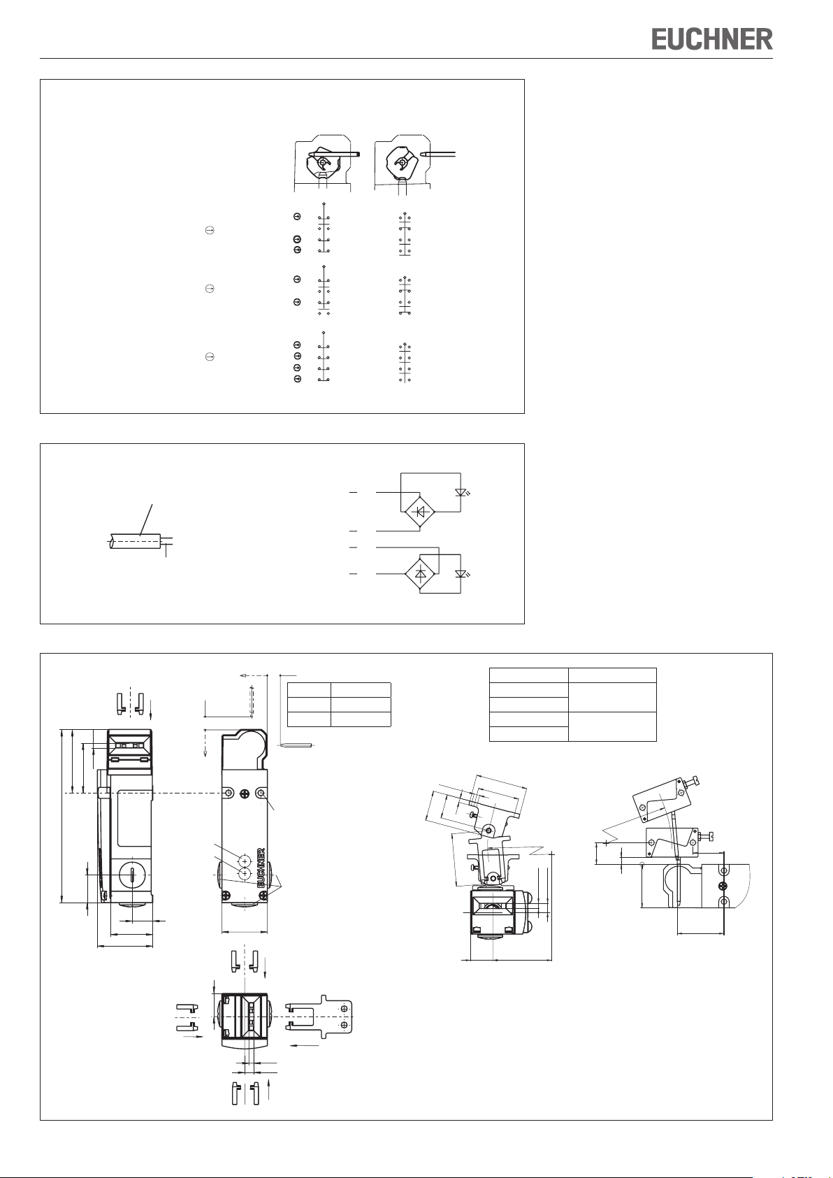
Ausführung Schaltglieder
NX.-2131...
NX.-3131...
NX.-2121...
3 Öffner + 1 Schließer
2 Öffner + 2 Schließer
4 Öffner
Bild 3: Schaltelemente und Schaltfunktionen
Litze
Tür
geschlossen
Tür
offen
Haftungsausschluss bei
nicht bestimmungsgemäßem Gebrauch
Nichteinhalten der Sicherheitshinweise
Anbau und elektrischem Anschluss nicht durch
autorisiertes Fachpersonal.
nicht durchgeführten Funktionskontrollen.
EG-Konformitätserklärung
Der nachstehende Hersteller erklärt hiermit, dass
das Produkt in Übereinstimmung ist mit den Bestimmungen der nachfolgend aufgeführten Richtlinie(n)
und dass die jeweiligen Normen zur Anwendung
gelangt sind.
EUCHNER GmbH + Co. KG
Kohlhammerstraße 16
70771 Leinfelden-Echterdingen, Deutschland
Angewendete Richtlinien:
Maschinenrichtlinie 2006/42/EG
Angewendete Normen:
EN 60947-5-1:2004 + Cor.:2005 + A1:2009
EN 1088:1995+A2:2008
Leinfelden, Juli 2010
Dipl.-Ing. Michael Euchner
Geschäftsführer
Duc Binh Nguyen
Dokumentationsbevollmächtigter
Die unterzeichnete EG-Konformitätserklärung ist
dem Produkt beigelegt.
Max. anschließbarer
Außendurchmesser 1,0mm
frei verdrahtbar
Bild 4: Anschlussbelegung optionales LED-Modul NX...L024...
Eintauchtiefe
Betätiger Eintauchtiefe s
Eintauchtiefe
Bild 5: Maßzeichnung NX..., Eintauchtiefe und Anfahrradien
Optionale
LED
Standard 32 + 1
Nachlauf 32 + 8
Betätiger separat bestellen
für M5 > 45 mm
ISO 1207 (DIN 84)S
ISO 4762 (DIN 912)
NX...M: M20x1,5
NX...N: 1/2" NPT
Betätigertyp Türradius min. [mm]
BETAETIGER-X-GQ
BETAETIGER-X-WQ
BETAETIGER-X-GNQ
BETAETIGER-X-WNQ
300
440
Radiusbetätiger X-OU-NRadiusbetätiger X-LR-N
Technische Änderungen vorbehalten, alle Angaben ohne Gewähr. © EUCHNER GmbH + Co. KG 093784-04-10/10 Originalbetriebsanleitung
Page 3
Betriebsanleitung Sicherheitsschalter NX...
Technische Daten
Parameter Wert
Gehäusewerkstoff Leichtmetall-Druckguss, kathodisch
Schutzart nach IEC 60529
NX1...
Mech. Lebensdauer 2x10⁶ Schaltspiele
Umgebungstemperatur -20...+80°C
Verschmutzungsgrad (extern,
nach EN 60947-1)
Einbaulage beliebig
Anfahrgeschwindigkeit max. 20 m/min
Betätigungskraft max. 40 N
Auszugskraft 50 N
Rückhaltekraft 10 N
Betätigungshäufigkeit max. 6700 / h
Schaltprinzip Schleichschaltglied
Kontaktwerkstoff Silberlegierung hauchvergoldet
Anschlussart NX1... Schraubanschluss
Leiterquerschnitt
(starr/flexibel) NX1...
Betriebsspannung für
optionale LED-Anzeige
Schaltspannung min.
bei 10 mA
Schaltstrom min. bei 24 V 1 mA
Kurzschlussschutz (Steuer-si-
cherung) nach IEC 60269-1
Konv. thermischer Strom Ith4 A
Gebrauchskategorie nach
EN 60947-5-1
AC-15
DC-13
Bemessungsstoßspannungsfestigkeit
Bemessungsisolationsspannung
Bedingter Kurzschlussstrom 100 A
Zuverlässigkeitswerte nach EN ISO 13849-1
B
10d
tauchlackiert
IP67
3 (Industrie)
0,34 mm² ... 1,5 mm²
L024 AC/DC 24 V +10%, -15%
12 V
4 A gG
4 A 230 V
4 A 24 V
U
= 2,5 kV
imp
Ui = 250 V
6
4,5 x 10
Page 4
Operating Instructions Safety Switches NX...
A
Correct Use
Safety switches series NX are interlocking devices
without guard locking.
In combination with a separating safety guard, this
safety component prevents dangerous machine
movements from being performed for as long as the
safety guard is open. A stop command is triggered
if the safety guard is opened during the dangerous
machine function.
The safety switches series NX comply with the regulations of EN 60947-5-1 (incl. Annex K) and comply
with the requirements of the employers' liability
insurance associations for machines, installations
and personnel protection.
Before safety switches are used, a risk assessment
must be performed on the machine in accordance
with
EN ISO 13849-1, Safety of machinery. Safety re-
lated parts of control systems. General principles
for design
EN ISO 14121, Safety of machinery. Risk assess-
ment. Principles.
IEC 62061, Safety of machinery – Functional
safety of safety-related electrical, electronic and
programmable electronic control systems.
Correct use includes compliance with the relevant
requirements for installation and operation, in
particular
EN ISO 13849-1, Safety of machinery. Safety re-
lated parts of control systems. General principles
for design
EN 1088, Safety of machinery. Interlocking
devices associated with guards. Principles for
design and selection
EN 60204-1, Safety of machinery. Electrical equip-
ment of machines. General requirements.
Important:
The user is responsible for safe integration of the
device in a safe overall system. For this purpose
the overall system must be validated, e.g. in accordance with EN ISO 13849-2.
If the simplified method according to section 6.3
EN ISO 13849-1:2008 is used for validation, the
Performance Level (PL) may be reduced if several
devices are connected one after the other.
If a product data sheet is included with the product,
the information on the data sheet applies in case of
discrepancies with the operating instructions.
Safety Precautions
Safety switches perform a personal protection
function. Incorrect installation or tampering can
lead to severe injuries to personnel.
Safety components must not be bypassed
(bridging of contacts), turned away, removed
or otherwise rendered ineffective.
On this topic pay attention in particular to the
measures for reducing the possibility of bypassing
according to EN 1088:1995.A2:2008, sec. 5.7.
The switching operation may only be triggered
by actuators specially provided for this purpose which are permanently connected to the
protective guard.
Mounting, electrical connection and setup only
by authorized personnel.
Function
The safety switch signals that the safety guard is
closed.
The switch does not perform guard locking!
Closing
The safety contacts are closed by inserting the
actuator.
Opening
The safety contacts are positively opened by withdrawing the actuator.
Installation
Safety switches and actuators must not be used
as an end stop.
Mount the safety switch only in assembled
condition!
Assemble the safety switch so that
access to the switch is difficult for operating per-
sonnel when the safety guard is open.
address programming, inspection and replace-
ment by authorized personnel are possible.
Insert the actuator in the actuating head.
Mount the safety switch positively.
Permanently connect the actuator to the safety
guard so that it cannot be detached, e.g. using
the enclosed non-removable screws, rivets or
welding.
Fit an additional end stop for the movable part of
the safety guard.
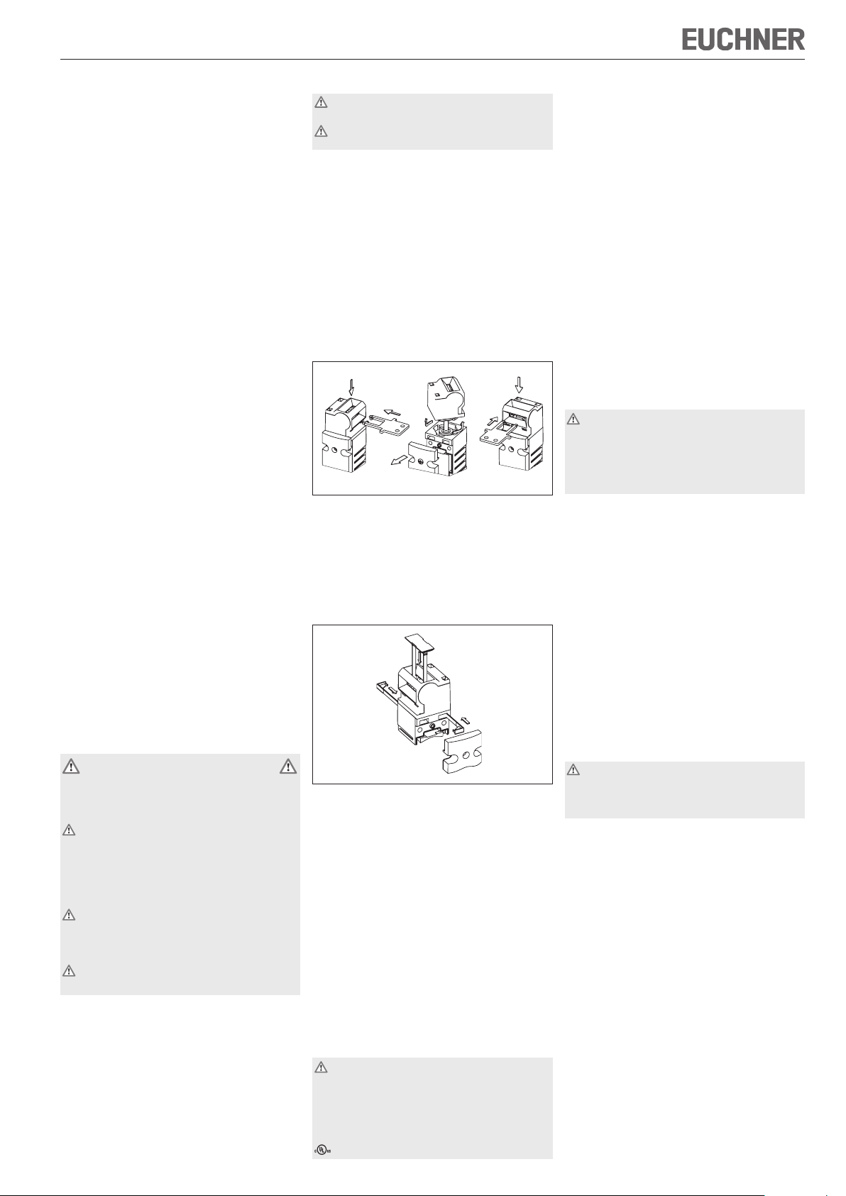
Changing the Actuating Direction
Figure 1: Changing the actuating direction
Unscrew and open switch cover.
Remove actuating head from the switch by turn-
ing and refit in the required position (bayonet
fastening).
Fit locking pins for protection against twisting
(Figure 2). It is then not possible to change the
actuating direction again.
Figure 2: Fitting the locking pins and the slot cover
Close the cover and screw in position.
Cover the unused actuating slot with the enclosed
slot covers (Figure 2).
Protection Against Environmental Influences
A lasting and correct safety function requires that
the actuating head must be protected against the
penetration of foreign bodies such as swarf, sand,
blasting shot, etc.
Cover the unused actuating slot with the slot
cover.
Cover the actuating slot, the actuator and the rating
plate during painting work!
Only use solvent-free cleaning agents to clean the
switch!
Electrical Connection
When choosing the insulation material and wire
for the connections, pay attention to the overtemperature in the housing (depending on the
operating conditions)!
For NX without plug connector:
For use and applications as per the requirements of
, copper wire 60/75 °C is to be used.
Version NX1... (cable entry M20x1.5/NPT ½",
see rating plate)
Unscrew locking screw for the required insertion
opening.
Fit cable gland M20x1.5 or NPT½".
Important: To achieve the specified degree of
protection, use a cable gland from EUCHNER (order.
no. 110 132, 110 133 or 110 134).
Conductor cross-section from 0.34 mm² to max.
1.5 mm².
For pin assignment see Figure 3.
Tighten the screws with a torque of 0.6 Nm.
Check that the cable entry is sealed.
Close the cover and screw in position.
Optional LED module L024
Max. outer diameter that can be connected
1.0 mm.
For pin assignment see Figure 4.
Due to the restricted space for wiring, use wires
as thin as possible (recommendation 0.25 mm²)!
Observe current rating of the wire!
Functional Check
Warning! Danger of fatal injury as a result of
faults in installation and functional check.
Before carrying out the functional check, make
sure that there are no persons in the danger
area. Observe the valid accident prevention
regulations.
After installation and any fault, the safety function
must be fully checked. Proceed as follows:
Mechanical function test
The actuator must slide easily into the actuating
head. Close the safety guard several times to check
the function.
Electrical function test
1. Switch on operating voltage.
2. Close all safety guards.
The machine must not start automatically.
3. Enable operation in the control system.
4. Open the safety guard.
The machine must switch off and it must not be
possible to start it as long as the safety guard
is open.
Repeat steps 2 - 4 for each safety guard.
Inspection and Service
If damage or wear is found, the complete switch
and actuator assembly must be replaced.
Replacement of individual parts or assemblies
is not permitted!
No servicing is required, but regular inspection
of the following is necessary to ensure trouble-free
long-term operation:
correct switching function
secure mounting of components
dirt and wear
sealing of cable entry
loose cable connections or plug connectors.
Note:The year of manufacture can be seen in the
bottom, right corner of the rating plate.
Exclusion of Liability under the Following
Conditions:
incorrect use
non-compliance with safety regulations
installation and electrical connection not per-
formed by authorized personnel
failure to perform functional checks.
Page 5

Operating Instructions Safety Switches NX...
EUCHNER GmbH + Co. KG Kohlhammerstraße 16 D-70771 Leinfelden-Echterdingen Tel. +49/711/75 97-0 Fax +49/711/75 33 16 www.euchner.de info@euchner.de
4,5
42
s
s
RD
GN
51,5
46
58,
5
39
19
25,
5
160
4,
5
21,
5
8,5
C
B
D
A
Standard
D
21
11 12
22
31 32
4241
21
13
14
22
33
34
42
41
21
11
12
22
33
34
42
41
41
33
11
21
42
34
22
12
21
41
31
11
12
22
32
42
41
33
13
21
42
34
22
14
GN
RD
24V
24V
0V
0V
KL3
KL2
KL1
KL4
Ø
40
16
20
50
40
28
14
61
13,5
21,5
8
R > 10
0
7
21
30
45
32+8
5,5
8,8
21,5
Ø
5,
5
40
R>100
*=R
5,1
51
4
23
29
50
Door closed Door open
Version Switching contacts
NX.-2131...
NX.-3131...
NX.-2121...
Figure 3: Switching elements and switching functions
3 NC contacts +
1 NO contact
2 NC contacts +
2 NO contact
4 NC contacts
EC declaration of conformity
The manufacturer named below herewith declares
that the product fulfils the provisions of the
directive(s) listed below and that the related standards have been applied.
EUCHNER GmbH + Co. KG
Kohlhammerstrasse 16
70771 Leinfelden-Echterdingen, Germany
Directives applied:
Machinery directive 2006/42/EC
Standards applied:
EN 60947-5-1:2004 + Cor.:2005 + A1:2009
EN 1088:1995+A2:2008
Leinfelden, July 2010
Dipl.-Ing. Michael Euchner
Director
Duc Binh Nguyen
Authorized representative empowered to draw up
documentation
The signed EC declaration of conformity is included
with the product.
Wire
Max. outer diameter that can be
connected 1.0mm
can any wiring as
required
Figure 4: Pin assignment optional LED module NX...L024...
Insertion depth
Actuator Insertion depth s
Insertion
depth
Figure 5: Dimension drawing NX..., insertion depth and approach radii
Optional
LED
Standard 32 + 1
Overtravel 32 + 8
Order actuator separately
for M5 > 45 mm
ISO 1207 (DIN 84)S
ISO 4762 (DIN 912)
NX...M: M20x1.5
NX...N: 1/2" NPT
Actuator type Door radius min. [mm]
ACTUATOR-X-GQ
ACTUATOR-X-WQ
ACTUATOR-X-GNQ
ACTUATOR-X-WNQ
300
440
Hinged actuator X-OU-NHinged actuator X-LR-N
Subject to technical modifications; no responsibility is accepted for the accuracy of this information. © EUCHNER GmbH + Co. KG 093784-04-10/10 (translation of the original operating instructions)
Page 6

Operating Instructions Safety Switches NX...
Technical Data
Parameter Value
Housing material Die-cast alloy, cathodically dipped
Degree of protection accord-
ing to 60529 NX1...
Mech. Mechanical life 2x10⁶ operations
Ambient temperature -20 ... +80°C℉
Degree of contamination
(external, according to
EN 60947-1)
Installation position Any
Approach speed, max. 20 m/min
Actuating force, max. 40 N
Extraction force 50 N
Retention force 10 N
Actuation frequency, max. 6700 / h
Switching principle Slow-action switching contact
Contact material Silver alloy, gold flashed
Connection type NX1... Screw terminal
Conductor cross-section
(rigid/flexible) NX1...
Operating voltage for optional
LED indicator
Switching voltage, min.,
at 10 mA
Switching current, min.,
at 24 V
Short circuit protection
(control circuit fuse)
according to IEC 60269-1
Conv. thermal current I
Utilization category
acc. to EN 60947-5-1
AC-15
DC-13
Rated impulse withstand
voltage
Rated insulation voltage Ui = 250 V
Conditional short-circuit
current
Reliability figures according to EN ISO 13849-1
B
10d
IP67
3 (industrial)
0.34 mm² ... 1.5 mm²
L024 AC/DC 24 V +10%, -15%
12 V
1 mA
4 A gG
4 A
th
4 A 230 V
4 A 24 V
U
= 2.5 kV
imp
100 A
6
4.5 x 10
Page 7

Mode d’emploi pour les interrupteurs de sécurité NX...
A
Utilisation conforme
Les interrupteurs de sécurité de la série NX sont des
dispositifs de verrouillage sans système d’interverrouillage.
Utilisé avec un protecteur, ce composant de sécurité
interdit tout mouvement dangereux de la machine tant
que le protecteur est ouvert. Un ordre d’arrêt est émis
en cas d’ouverture du protecteur pendant le fonctionnement dangereux de la machine.
Les interrupteurs de sécurité de la série NX répondent
aux prescriptions EN 60947-5-1 (incl. Annexe K) et
satisfont aux exigences des organismes professionnels concernant les machines, les installations et la
protection des personnes.
Avant d'utiliser des interrupteurs de sécurité, il est
nécessaire d'effectuer une analyse d'appréciation du
risque sur la machine selon
EN ISO 13849-1, Parties des systèmes de com-
mande relatives à la sécurité ;
EN ISO 14121, Sécurité des machines, appréciation
du risque.
IEC 62061, Sécurité des machines – Sécurité fonc-
tionnelle des systèmes de commande électriques,
électroniques et électroniques programmables relatifs
à la sécurité.
Pour que l’utilisation soit conforme, les instructions
applicables au montage et à la mise en service doivent
être respectées, en particulier
EN ISO 13849-1, Parties des systèmes de com-
mande relatives à la sécurité ;
EN 1088, Dispositifs de verrouillage associés à des
protecteurs ;
EN 60204-1, Equipement électrique des machines.
Important :
L’utilisateur est responsable de la sécurité de l'inté-
gration de l'appareil dans un système global sécurisé.
Ce dernier doit être validé à cet effet, par ex. selon
EN ISO 13849-2.
Si la validation fait appel à la procédure simplifiée
selon le paragraphe 6.3 EN ISO 13849-1:2008,
le niveau de performance ou Performance Level
(PL) peut diminuer lorsque plusieurs appareils sont
raccordés en série l'un à la suite de l'autre.
Si le produit est accompagné d'une fiche technique,
les indications de cette dernière prévalent en cas
de différences avec les indications figurant dans le
mode d'emploi.
Consignes de sécurité
Les interrupteurs de sécurité remplissent une fonction
de protection des personnes. Le montage ou les
manipulations non conformes peuvent engendrer de
graves blessures.
Les éléments de sécurité ne doivent pas être
contournés (pontage des contacts), déplacés,
retirés ou être inactivés de quelque manière que
ce soit.
Tenez compte en particulier des mesures de réduction des possibilités de fraude selon EN 1088:1995.
A2:2008, paragr. 5.7.
La manœuvre ne doit être déclenchée que par les
languettes prévues spécialement à cet effet et
reliées de manière indissociable au protecteur.
Montage, raccordement électrique et mise en
service exclusivement par un personnel habilité.
Fonction
L’interrupteur de sécurité signale que le protecteur
est fermé.
L'interrupteur n'actionne aucun système d'interverrouillage !
Fermeture
Les contacts de sécurité se ferment à l'introduction
de la languette.
Ouverture
Les contacts de sécurité s'ouvrent au retrait de la
languette.
Montage
Les interrupteurs de sécurité et les éléments
d'actionnement ne doivent pas être utilisés comme
butée.
Ne fixer qu'assemblé !
Monter l'interrupteur de sécurité de manière à ce que
Il soit difficilement accessible au personnel opérateur
lorsque le protecteur est ouvert.
l'entretien et le remplacement soient possibles.
Introduire la languette dans la tête d’actionnement.
Fixer l'interrupteur de sécurité de façon permanente ;
Relier la languette au protecteur de manière durable
et de sorte qu'elle ne puisse être démontée, par ex.
avec les vis à usage unique fournies, par rivetage
ou soudage.
Mettre en place une butée supplémentaire pour la
partie mobile du protecteur.
Changement du sens d'actionnement
Figure 1 : Changement du sens d'actionnement
Dévisser et ouvrir le couvercle de l'interrupteur.
Retirer la tête d’actionnement de l’interrupteur en la
tournant et la reposer dans la position voulue (fixation
baïonnette).
Utiliser les cales de sécurité fournies comme protection antitorsion (fig. 2). Il n’est alors plus possible de
changer ultérieurement le sens d’actionnement.
Figure 2 : Mise en place des cales de sécurité et du
l’obturateur de fente
Fermer le couvercle de l'interrupteur et le visser.
Obturer l’ouverture d'actionnement non utilisée à l’aide
du capuchon (Fig. 2).
Protection contre les influences ambiantes
La condition pour garantir une fonction de sécurité durable et parfaite est de protéger la tête d'actionnement
contre la pénétration de corps étrangers comme les
copeaux, le sable, les grenailles, etc.
Obturer l’ouverture d'actionnement non utilisée à l’aide
du capuchon de fente fourni.
En cas de laquage, couvrir l'ouverture d'actionnement,
la languette et la plaque signalétique !
Pour nettoyer les interrupteurs, utiliser uniquement des
produits de nettoyage exempts de solvants !
Raccordement électrique
Tenir compte, pour le choix du matériau isolant
ou des conducteurs, de la température élevée
régnant à l'intérieur du boîtier (selon les conditions
de fonctionnement) !
Pour NX sans connecteur :
Pour que l’utilisation soit conforme aux exigences de
, utiliser un câble de cuivre 60/75 °C.
Retirer la vis de protection de l'ouverture du presse-
étoupe souhaitée.
Monter le presse-étoupe M20x1,5 ou NPT½".
Important : utiliser le presse-étoupe EUCHNER (réf.
110 132, 110 133 ou 110 134) afin de respecter
l'indice de protection indiqué.
Section de conducteur de 0,34 mm² à max.
1,5 mm².
Pour l'affectation des broches, voir fig. 3.
Serrer les vis de connexion au couple de 0,6 Nm.
Veiller à l'étanchéité à l'entrée du câble.
Fermer le couvercle de l'interrupteur et le visser.
Diamètre extérieur raccordable 1,0 mm maxi.
Pour l'affectation des broches, voir fig. 4.
Utiliser les conducteurs les plus fins possibles du fait de
l’étroitesse de l’espace de câblage (recommandation :
0,25 mm²) ! Respecter l’intensité maximale admissible
des conducteurs !
Contrôle fonctionnel
Assurez-vous que personne ne se trouve dans
Procéder à un contrôle complet de la fonction de
sécurité à l'issue de l'installation et après la survenue
d'un défaut. Procédez de la manière suivante :
La languette doit rentrer facilement dans la tête d’actionnement. Pour le contrôle, fermer plusieurs fois le
protecteur.
1. Enclencher la tension de service.
2. Fermer tous les protecteurs.
La machine ne doit pas démarrer automatique-
ment.
3. Valider le fonctionnement dans la commande.
4. Ouvrir le protecteur.
La machine doit s'arrêter et ne plus pouvoir être
redémarrée tant que le protecteur est ouvert.
Répétez les étapes 2 - 4 individuellement pour chaque
protecteur.
Contrôle et entretien
Le remplacement de composants ou de sous-
Aucun entretien n'est nécessaire. Pour garantir un
fonctionnement irréprochable et durable, il convient
toutefois de vérifier régulièrement les points
suivants :
Fonction de commutation correcte
Bonne fixation des composants
Dépôts et usure
Étanchéité à l’entrée du câble
Serrage des connexions ou des connecteurs
Remarque :
inférieur droit de la plaque signalétique.
Nous déclinons toute responsabilité
en cas d’utilisation non conforme ;
en cas de non-respect des consignes de sécurité ;
si le montage et le raccordement électrique ne sont
pas effectués par du personnel agréé ;
si les contrôles fonctionnels ne sont pas effectués.
Version NX1... (Entrée de câble M20x1,5/NPT½"
voir plaque signalétique)
Module de LED L024 en option
Avertissement ! Risque de blessures mortelles en
cas d'erreurs lors de l'installation ou du contrôle
fonctionnel.
la zone de danger avant de débuter le contrôle
fonctionnel. Observez les consignes en vigueur
relatives à la prévention des accidents.
Contrôle du fonctionnement mécanique
Contrôle du fonctionnement électrique
En cas d'endommagement ou d'usure, il est né-
cessaire de remplacer entièrement l'interrupteur
avec l'élément d'actionnement.
ensembles n'est pas autorisé !
l'année de construction figure dans le coin
Page 8

Mode d’emploi pour les interrupteurs de sécurité NX...
EUCHNER GmbH + Co. KG Kohlhammerstraße 16 D-70771 Leinfelden-Echterdingen Tél. +49/711/75 97-0 Fax +49/711/75 33 16 www.euchner.de info@euchner.de
4,5
42
s
s
RD
GN
51,5
46
58,
5
39
19
25,
5
160
4,
5
21,
5
8,5
C
B
D
A
Standard
D
21
11 12
22
31 32
4241
21
13
14
22
33
34
42
41
21
11
12
22
33
34
42
41
41
33
11
21
42
34
22
12
21
41
31
11
12
22
32
42
41
33
13
21
42
34
22
14
GN
RD
24V
24V
0V
0V
KL3
KL2
KL1
KL4
Ø
40
16
20
50
40
28
14
61
13,5
21,5
8
R > 10
0
7
21
30
45
32+8
5,5
8,8
21,5
Ø
5,
5
40
R>100
*=R
5,1
51
4
23
29
50
Déclaration de conformité CE
Porte fermée Porte ouverte
Modèle Contacts
NX.-2131...
NX.-3131...
NX.-2121...
3 contacts à ouverture +
1 contact à fermeture
2 contacts à ouverture +
2 contacts à fermeture
4 contacts à ouverture
Figure 3 : Eléments de commutation et fonctions de commutation
Le fabricant ci-dessous déclare par la présente que
le produit est conforme aux dispositions de la ou des
directive(s) précisées ci-après ainsi qu’aux normes qui
lui sont applicables.
EUCHNER GmbH + Co. KG
Kohlhammerstraße 16
D-70771 Leinfelden-Echterdingen, Allemagne
Directives utilisées :
Directive Machines 2006/42/CE
Normes utilisées :
EN 60947-5-1:2004 + Cor.:2005 + A1:2009
EN 1088:1995+A2:2008
Leinfelden, juillet 2010
Dipl.-Ing. Michael Euchner
Directeur Général
Duc Binh Nguyen
Responsable documentation
La déclaration de conformité CE signée est jointe au
produit.
Conducteur
Diamètre extérieur raccordable
1,0 mm maxi.
câblage libre
Figure 4 : Affectation des broches du module de LED NX...L024... en option
Profondeur d'insertion
Languette Prof. d'insert. s
Profondeur
d'insertion
Figure 5 : Dimensions NX..., profondeur d’insertion et rayons d’entrée
LED
en option
Standard 32 + 1
Surcourse 32 + 8
Languette à commander séparément
pour M5 > 45 mm
ISO 1207 (DIN 84)S
ISO 4762 (DIN 912)
NX...M : M20x1,5
NX...N : 1/2" NPT
Type languette Rayon porte min. [mm]
LANGUETTE X-GQ
LANGUETTE X-WQ
LANGUETTE X-GNQ
LANGUETTE X-WNQ
300
440
Languette X-OU-NLanguette X-LR-N
Sous réserve de modifications techniques, indications non contractuelles. © EUCHNER GmbH + Co. KG 093784-04-10/10 trad. mode d'emploi d'origine
Page 9

Mode d’emploi pour les interrupteurs de sécurité NX...
Caractéristiques techniques
Paramètre Valeur
Matériau du boîtier Alliage léger moulé sous pression,
Indice de protection selon
IEC 60529 NX1...
Manoeuvres mécaniques 2x10⁶ manoeuvres
Température ambiante -20 à +80° C℉
Degré de pollution (externe,
selon EN 60947-1)
Position de montage Au choix
Vitesse d’actionnement maxi. 20 m/min
Force de traction maxi. 40 N
Force de retrait 50 N
Force de maintien 10 N
Fréquence d'actionnement maxi.6700/h
Principe de commutation Contact à action lente
Matériau des contacts Alliage argent doré par soufflage
Type de raccordement NX1... Borne à vis
Section des conducteurs
(rigides/flexibles) NX1...
Tension de service pour indica-
tion par LED en option
Tension de commutation mini.
à 10 mA
Pouvoir de coupure mini.
(pour 24 V)
Protection contre les courts-
circuits (fusible de commande)
selon IEC 60269-1
Courant thermique conv. Ith4 A
Catégorie d'emploi selon
EN 60947-5-1
AC-15
DC-13
Tension nominale d’essai
(impulsion)
Tension nominale d’isolement Ui = 250 V
Courant conditionnel de court-
circuit
Valeurs de fiabilité selon EN ISO 13849-1
B
10d
peinture galvanisée par électrolyse
IP67
3 (industrie)
0,34 mm² ... 1,5 mm²
L024 AC/DC 24 V +10%, -15%
12 V
1 mA
4 A gG
4 A 230 V
4 A 24 V
U
= 2,5 kV
imp
100 A
6
4,5 x 10
Page 10

Istruzioni di impiego dei finecorsa di sicurezza NX...
A
Impiego conforme alla destinazione d'uso
I finecorsa di sicurezza della serie NX sono dispositivi
di interblocco senza meccanismo di ritenuta.
In combinazione con un riparo, questo componente
di sicurezza impedisce i movimenti pericolosi della
macchina quando il riparo è aperto. Se, durante una
funzione pericolosa della macchina, il riparo di protezione viene aperto si genera un ordine di arresto.
I finecorsa di sicurezza della serie NX sono conformi
alla normativa EN 60947-5-1 (compreso l'allegato K),
nel rispetto anche delle norme dell'istituto di assicurazione contro gli infortuni sul lavoro relative alle macchine, agli impianti e alla protezione delle persone.
Prima di impiegare i finecorsa di sicurezza, la macchina deve essere stata oggetto di una valutazione del
rischio, conformemente alle norme:
EN ISO 13849-1, Parti dei sistemi di comando legate
alla sicurezza.
EN ISO 14121, Sicurezza del macchinario, valuta-
zione del rischio.
IEC 62061, Sicurezza del macchinario – Sicurezza
funzionale dei sistemi di comando e controllo elettrici,
elettronici ed elettronici programmabili correlati alla
sicurezza.
L'impiego conforme alla destinazione d'uso implica il
rispetto delle vigenti norme relative all'installazione e
all'esercizio, in particolare
EN ISO 13849-1, Parti dei sistemi di comando legate
alla sicurezza.
EN 1088, Dispositivi di interblocco associati ai
ripari
EN 60204-1, Equipaggiamento elettrico delle
macchine.
Importante:
L'utente è responsabile per l'integrazione sicura del
dispositivo nel sistema generale. A questo scopo,
il sistema generale deve essere validato p. es.
secondo la EN ISO 13849-2.
Se per la validazione si ricorre alla procedura
semplificata secondo la sezione 6.3 della EN ISO
13849:2008, si ridurrà eventualmente il Performance Level (PL) se vengono collegati in serie più
dispositivi.
Se al prodotto è allegata una scheda tecnica, valgono
le indicazioni della stessa, qualora fossero diverse da
quanto riportato nelle istruzioni di impiego.
Avvertenze di sicurezza
I finecorsa di sicurezza svolgono una funzione di protezione degli operatori. Un'installazione inadeguata o
eventuali manomissioni possono causare gravi lesioni
alle persone.
I componenti di sicurezza non devono essere né
aggirati (ponticellando i contatti), né rimossi, né
girati, né resi inefficaci in altra maniera.
Osservare in proposito le misure per la ruduzione
delle possibilità di manomissione secondo la EN
1088:1995.A2:2008, sezione 5.7.
La commutazione deve avvenire solo mediante gli
appositi azionatori, collegati irremovibilmente al
riparo di protezione.
L'installazione, il collegamento elettrico e la messa
in servizio sono da affidare esclusivamente al
personale specializzato e autorizzato.
Funzionamento
Il finecorsa di sicurezza segnala la chiusura del riparo
di protezione.
Il finecorsa non effettua il bloccaggio del riparo!
Chiusura
I contatti di sicurezza vengono chiusi in seguito all'introduzione dell'azionatore.
Apertura
I contatti di sicurezza, ad apertura forzata, vengono
aperti in seguito all'estrazione dell'azionatore.
Montaggio
Il finecorsa di sicurezza e l'azionatore non devono
essere utilizzati come riscontro meccanico di
arresto.
Fissare solo da assemblato!
Installare il finecorsa di sicurezza in modo che
sia difficilmente accessibile al personale di servizio
quando il riparo di protezione è aperto,
manutenzione e sostituzione siano possibili.
Introdurre l'azionatore nella testina di azionamento.
Installare il finecorsa di sicurezza con un corretto
accoppiamento meccanico.
Fissare l'azionatore al riparo di protezione in modo
che non sia asportabile, usando ad esempio le viti non
svitabili incluse, rivetti, chiodatura o saldatura.
Prevedere una battuta supplementare per la parte
mobile del riparo di protezione.
Modifica della direzione di azionamento
Fig. 1: Modifica della direzione di azionamento
Aprire il coperchio del finecorsa svitandolo.
Rimuovere la testina di azionamento svitandola dal
finecorsa e montarla di nuovo nella posizione desiderata (fissaggio a baionetta).
Come protezione antitorsione applicare i cunei di
fissaggio inclusi (figura 2). Ciò rende impossibile un’ulteriore modifica della direzione di azionamento.
Fig. 2: Introduzione dei cunei di fissaggio e della
copertura dell’intaglio
Chiudere ed avvitare il coperchio del finecorsa.
Chiudere gli intagli di comando non utilizzati insieme
alle relative coperture (figura 2).
Protezione contro gli agenti ambientali
Premessa necessaria per un corretto e durevole
funzionamento in sicurezza è che nella testina di
azionamento non entrino corpi estranei quali trucioli,
sabbia, graniglia, ecc.
Chiudere l'intaglio di comando non utilizzato con le
apposite coperture.
Prima dei lavori di verniciatura coprire l'intaglio di comando, l'azionatore e l'etichetta di identificazione.
Per la pulizia degli interruttori, utilizzare esclusivamente
detergenti privi di solventi.
Collegamento elettrico
Nella scelta del materiale isolante o dei cavi di
collegamento, prestare attenzione alla sovratemperatura presente nella custodia (dipendente dalle
condizioni di funzionamento).
Per i TP senza connettore vale:
per l’impiego e l’utilizzo in conformità ai requisiti
si devono utilizzare cavi in rame 60/75 °C.
Esecusione NX1... (foro per cavo cavo M20x1,5/
NPT ½" vedere targhetta di identificazione)
Estrarre il pressacavo dell’apertura di inserimento
desiderata.
Montare il pressacavo M20x1,5 o NPT½".
Importante: per raggiungere il grado di protezione
indicato, utilizzare un collegamento a pressacavo
EUCHNER (N. ord. 110 132, 110 133 o 110 134).
Sezione dei conduttori da 0,34 mm² fino a max.
1,5 mm².
Disposizione dei contatti: vedere fig. 3.
Serrare le viti con 0,6 Nm.
Accertarsi che il foro per cavo sia a tenuta.
Chiudere ed avvitare il coperchio del finecorsa.
Modulo LED opzionale L024
Max. diametro esterno cavo 1,0 mm.
Disposizione dei contatti: vedere fig. 4.
Per il limitato spazio disponibile per il cablaggio è
preferibile utilizzare cavi sottili (dimensioni consigliate
0,25 mm²). Rispettare la portata di corrente del
cavo.
Controllo funzionale
Avvertenza! Lesioni mortali in caso di errori
durante l'installazione e il controllo funzionale.
Prima di procedere al controllo funzionale,
assicurarsi che nessuna persona si trovi nella
zona pericolosa. Osservare tutte le normative
antinfortunistiche vigenti.
Al termine dell'installazione e dopo ogni guasto si deve
effettuare una verifica completa della funzione di sicurezza. Procedere come specificato di seguito:
Prova della funzione meccanica
L'azionatore deve potersi inserire facilmente nella testina di azionamento. Effettuare questa prova chiudendo
più volte il riparo di protezione.
Prova della funzione elettrica
1. Attivare la tensione di esercizio.
2. Chiudere tutti i ripari di protezione.
La macchina non deve avviarsi da sola.
3. Abilitare il funzionamento nel sistema di controllo.
4. Aprire il riparo di protezione.
La macchina deve arrestarsi e non deve essere
possibile avviarla, finché il riparo di protezione è
aperto.
Ripetere le operazioni 2 - 4 per ogni singolo riparo di
protezione.
Controllo e manutenzione
In caso di danneggiamenti o di usura si deve sosti-
tuire il finecorsa completo, incluso l'azionatore.
Non è ammessa la sostituzione di singoli compo
nenti o di blocchi!
Non sono necessari interventi di manutenzione. Per
garantire un funzionamento corretto e durevole si
consiglia comunque di controllare regolarmente
corretta commutazione
fissaggio dei singoli componenti
presenza di depositi o segni d'usura
la tenuta dell'ingresso del cavo
eventuale allentamento di collegamenti o connet-
tori.
Nota: l'anno di costruzione si trova sull'angolo destro
in basso della targhetta di identificazione.
Esclusione di responsabilità in caso di
impiego non conforme alla destinazione
mancato rispetto delle avvertenze di sicurezza
montaggio e collegamento elettrico non eseguiti da
personale specializzato ed autorizzato
omissione dei controlli funzionali.
-
Page 11

Istruzioni di impiego dei finecorsa di sicurezza NX...
EUCHNER GmbH + Co. KG Kohlhammerstraße 16 D-70771 Leinfelden-Echterdingen Tel. +49/711/75 97-0 Fax +49/711/75 33 16 www.euchner.de info@euchner.de
4,5
42
s
s
RD
GN
51,5
46
58,
5
39
19
25,
5
160
4,
5
21,
5
8,5
C
B
D
A
Standard
D
21
11 12
22
31 32
4241
21
13
14
22
33
34
42
41
21
11
12
22
33
34
42
41
41
33
11
21
42
34
22
12
21
41
31
11
12
22
32
42
41
33
13
21
42
34
22
14
GN
RD
24V
24V
0V
0V
KL3
KL2
KL1
KL4
Ø
40
16
20
50
40
28
14
61
13,5
21,5
8
R > 10
0
7
21
30
45
32+8
5,5
8,8
21,5
Ø
5,
5
40
R>100
*=R
5,1
51
4
23
29
50
Riparo chiuso Riparo aperto
Esecuzione Contatti
NX.-2131...
NX.-3131...
NX.-2121...
Fig. 3: Microinterruttori e commutazioni
3 contatti NC +
1 contatto NA
2 contatti NC +
2 contatti NA
4 contatti NC
Dichiarazione CE di conformità
Il fabbricante indicato di seguito dichiara che il
prodotto è conforme alle disposizioni della/delle direttiva/e sottoelencata/e e che sono state applicate
le norme pertinenti.
EUCHNER GmbH + Co. KG
Kohlhammerstraße 16
70771 Leinfelden-Echterdingen, Germania
Direttive applicate:
Direttiva Macchine 2006/42/CE
Norme applicate:
EN 60947-5-1:2004 + Cor.:2005 + A1:2009
EN 1088:1995+A2:2008
Leinfelden, luglio 2010
Dipl.-Ing. Michael Euchner
Amministratore delegato
Duc Binh Nguyen
Responsabile della documentazione
La dichiarazione CE di conformità firmata è allegata
al prodotto.
Cavi
Max. diametro esterno cavo
1,0mm
di facile cablaggio
Fig. 4: Schema di collegamento del modulo LED opzionale NX...L024...
Inserimento
Azionatori Inserimento s
Inserimento
Fig. 5: Dimensioni NX..., inserimento e raggi di azionamento
Led
opzionale
Standard 32 + 1
Oltrecorsa 32 + 8
Gli azionatori vanno ordinati separatamente.
Per M5 > 45 mm
ISO 1207 (DIN 84)S
ISO 4762 (DIN 912)
NX...M: M20x1,5
NX...M: 1/2" NPT
Tipo di azionatore Raggio riparo min. [mm]
AZIONATORE-X-GQ
AZIONATORE-X-WQ
AZIONATORE-X-GNQ
AZIONATORE-X-WNQ
300
440
Azionatore rotativo X-OU-NAzionatore rotativo X-LR-N
Con riserva di modifiche tecniche, tutti i dati sono soggetti a modifiche. © EUCHNER GmbH + Co. KG 093784-04-10/10 Traduzione delle istruzioni di impiego originali
Page 12

Istruzioni di impiego dei finecorsa di sicurezza NX...
Dati tecnici
Parametro Valore
Materiale custodia lega leggera pressofusa, con verni-
Grado di protezione sec.
IEC 60529 NX1...
Durata meccanica 2x10⁶ manovre
Temperatura ambiente -20...+80° C℉
Grado di inquinamento (ester-
no, secondo EN 60947-1)
Posizione di installazione qualsiasi
Velocità di azionamento max. 20 m/min
Forza di azionamento max. 40 N
Forza di estrazione 50 N
Forza di ritenuta 10 N
Frequenza di azionamento
max.
Principio di commutazione microinterruttore ad azione lenta
Materiale dei contatti lega di argento placcata oro
Tipo di collegamento NX1... collegamento a vite
Sezione del conduttore
(rigido/flessibile) NX1...
Tensione d'esercizio per
indicatore LED opzionale
Tensione di commutazione
min. a 10 mA
Corrente di commutazione
min. a 24 V
Protezione contro cortocircuiti
(fusibile di comando) secondo
IEC 60269-1
Corrente continua termica
standard I
th
Categoria di impiego secondo
EN 60947-5-1
AC-15
DC-13
Rigidità dielettrica nominale U
Tensione di isolamento
nominale
Corrente di cortocircuito
nominale
Valori di affidabilità secondo EN ISO 13849-1
B
10d
ciatura catodica ad immersione
IP67
3 (industria)
6700/h
0,34 mm² ... 1,5 mm²
L024 AC/DC 24 V +10%, -15%
12 V
1 mA
4 A gG
4 A
4 A 230 V
4 A 24 V
= 2,5 kV
imp
Ui = 250 V
100 A
6
4,5 x 10
 Loading...