

Page 1
Betriebsanleitung Sicherheitsschalter NM..HB
Bestimmungsgemäßer Gebrauch
Sicherheitsschalter der Baureihe NM..HB (Schwenkhebel) werden als Teile von Steuerungen eingesetzt,
die Sicherheitsfunktionen übernehmen, z. B. für
Schutzeinrichtungen oder als Positionsgeber.
Die Sicherheitsschalter der Baureihe NM entsprechen
den Vorschriften EN 60947-5-1, Anhang K und erfüllen die Anforderungen der Berufsgenossenschaften
für Maschinen, Anlagen und Personenschutz.
Vor dem Einsatz von Sicherheitsschaltern ist eine
Risikobeurteilung an der Maschine durchzuführen nach
EN ISO 13849-1, Sicherheitsbezogene Teile von
Steuerungen
EN ISO 14121, Sicherheit von Maschinen, Risikobeurteilung
IEC 62061, Sicherheit von Maschinen - Funktionale
Sicherheit sicherheitsbezogener elektrischer, elektronischer und programmierbarer elektronischer
Steuerungssysteme.
Zum bestimmungsgemäßen Gebrauch gehört das
Einhalten der einschlägigen Anforderungen für den
Einbau und Betrieb, insbesondere
EN ISO 13849-1, Sicherheitsbezogene Teile von
Steuerungen
EN 1088, Verriegelungseinrichtungen in Verbindung
mit trennenden Schutzeinrichtungen
EN 60204-1, Elektrische Ausrüstung von Maschinen.
Wichtig:
Der Anwender trägt die Verantwortung für die Einbindung des Geräts in ein sicheres Gesamtsystem.
Dazu muss das Gesamtsystem z.B. nach EN ISO
13849-2 validiert werden.
Wird zur Validierung das vereinfachte Verfahren nach
Abschnitt 6.3 EN ISO 13849-1:2008 benutzt, reduziert sich möglicherweise der Performance Level (PL), wenn mehrere Geräte hintereinander geschaltet werden.
Liegt dem Produkt ein Datenblatt bei, gelten die
Angaben des Datenblatts, falls diese von der
Betriebsanleitung abweichen.
Sicherheitshinweise
Sicherheitsschalter erfüllen eine PersonenschutzFunktion. Unsachgemäßer Einbau oder Manipulationen können zu schweren Verletzungen von Personen führen.
Sicherheitsbauteile dürfen nicht umgangen (Kontakte überbrückt), weggedreht, entfernt oder auf
andere Weise unwirksam gemacht werden.
Beachten Sie hierzu insbesondere die Maßnahmen
zur Verringerung der Umgehungsmöglichkeiten aus
EN 1088:1995+A2:2008, Abschn. 5.7.
Montage, elektrischer Anschluss und Inbetriebnahme ausschließlich durch autorisiertes Fachpersonal.
Funktion
Siehe Schaltwegdiagramm.
Montage
Sicherheitsschalter und Steuernocken dürfen
nicht als Anschlag verwendet werden.
Sicherheitsschalter und Steuernocken müssen so
angeordnet sein, dass sie gegen eine Veränderung
ihrer Position ausreichend gesichert sind.
Um diese Anforderungen zu erfüllen:
müssen die Befestigungselemente zuverlässig sein
und zum Zweck ihres Lösens ein Werkzeug erfordern.
Sicherheitsschalter formschlüssig anbauen.
Für sicherheitstechnische Anwendungen (fixierte
Positionierung) Schalter mit Schrauben M5x30 anbauen.
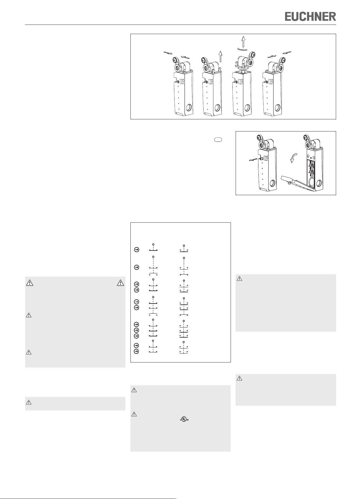
Bild 1: Umstellen der Betätigungsrichtung
Um den ordnungsgemäßen Betrieb sicherzustellen,
müssen die Steuernocken gemäß dem Maß
he Bild 4 und 5) angebracht sein.
Schutz vor Umgebungseinflüssen
Voraussetzung für eine dauerhafte und einwandfreie
Sicherheitsfunktion ist der Schutz des Betätigungskopfes vor eindringenden Fremdkörpern wie Spänen,
Sand, Strahlmitteln usw.
Bei Lackierarbeiten den Betätigungskopf, den Steuernocken und das Typenschild abdecken!
Zur Reinigung der Sicherheitsschalter nur lösungsmittelfreie Reinigungsmittel verwenden!
Schaltelemente und Schaltfunktionen
betätigt
21
22
22
21
13
14
31
32
21
22
31
32
21
22
13
14
31
32
21
22
11
12
22
21
11
12
Bild 2: Schaltelemente und Schaltfunktionen
Elektrischer Anschluss
Bei der Auswahl von Isolationsmaterial bzw. Anschlusslitzen, auf die Übertemperatur im Gehäu-
se (abhängig von den Betriebsbedingungen) achten!
Für den Einsatz und die Verwendung gemäß den
Anforderungen von muss eine class 2
Spannungsversorgung oder ein class 2 Transformator nach UL1310 oder UL1585 verwendet werden. Alternativ kann eine Kleinspannungsversorgung nach UL508 Tabelle 32.1 verwendet werden.
A
BetätigtNicht
21
22
NM01
21
22
13
31
21
31
21
13
31
21
11
21
11
NM11,
NM11..C2069
14
32
NM02
22
NM12
32
22
14
NM03
32
22
12
NM02..C2069
22
12
M=0,6Nm
+1
(sie-
41
0
Bild 3: Öffnen des Sicherheitsschalters
Gewünschte Einführöffnung ausbrechen.
Kabelverschraubung M16 x 1,5 mit entsprechender Schutzart montieren.
Leiterquerschnitt 0,34 mm2 ... 1,5 mm².
Kontaktbelegung siehe Bild 2.
Klemmschrauben mit 0,5 Nm anziehen.
Auf Dichtheit der Leitungseinführung achten.
Schalterdeckel schließen und verschrauben.
Funktionskontrolle
Bei geöffneter Schutzeinrichtung muss der
Sicherheitsschalter in jeder Stellung der Schutzeinrichtung betätigt sein (Überfahrsicherung).
In Sicherheitsschaltkreisen die Sicherheitsfunktion
überprüfen.
Die Maschine muss beim Betätigen des Sicherheitsschalters stoppen.
Die Maschine darf bei betätigtem Sicherheits-
schalter nicht starten.
Mechanische Funktionsprüfung
Das Betätigungselement auf Leichtgängigkeit prüfen.
Elektrische Funktionsprüfung
Schalter betätigen und die Schaltfunktion prüfen.
Kontrolle und Wartung
Bei Beschädigung oder Verschleiß muss der
gesamte Schalter mit Betätiger ausgetauscht
werden.
Der Austausch von Einzelteilen oder Baugruppen ist unzulässig!
Wartungsarbeiten sind nicht erforderlich. Um eine
einwandfreie und dauerhafte Funktion zu gewährlei-
sten, sind regelmäßige Kontrollen erforderlich auf
einwandfreie Schaltfunktion
sichere Befestigung der Bauteile
Ablagerungen und Verschleiß
Dichtheit der Kabeleinführung
gelockerte Leitungsanschlüsse bzw. Steckverbinder.
Hinweis: Das Baujahr ist in der unteren, rechten Ecke
des Typenschilds ersichtlich.
Page 2
Betriebsanleitung Sicherheitsschalter NM..HB
46
8
32
25
12,5
Nocken
0
+1
41
1,5
128,5
∅5
∅4,2
16,5
16
12,5
32
M16x1,5
C
M=0,6Nm
B
NM03
NM02
R
6
25
27
*
17
M=1 Nm
18
M=0,6Nm
25
M16x1,5
D
M=0,6Nm
A
Standard
0°
11-12
21-22
31-32
*fixierte Positionierung
für Sicherheitsanwendungen (M5)
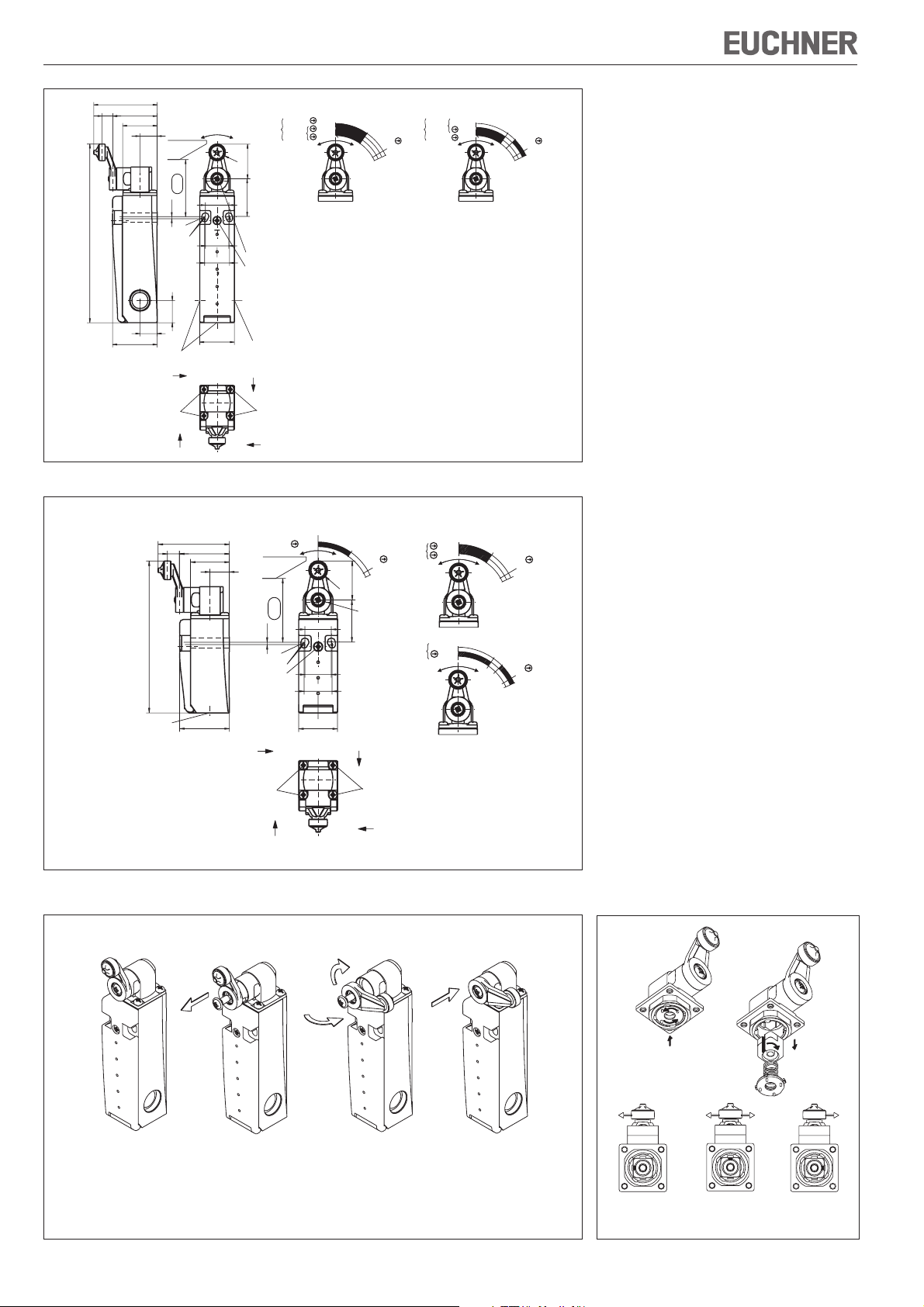
Bild 4: Maßzeichnung NM11HB / NM02HB / NM12HB / NM03HB
46
8
32
25
12,5
97,5
NM01
1,5
∅5
∅4,2
M=0,6Nm
0˚
21-22
0
+1
41
16,5
35˚
Nocken
R6
25
M=1 Nm
27
*
17
18
Haftungsausschluss bei
0°
35°
NM12
60°
6
5°
NM11
13-14
21-22
31-32
35°
45°
60
°
6
5
°
nicht bestimmungsgemäßem Gebrauch
Nichteinhalten der Sicherheitshinweise
Anbau und elektrischem Anschluss durch nicht autorisiertes Fachpersonal.
nicht durchgeführten Funktionskontrollen.
EG-Konformitätserklärung
Der nachstehende Hersteller erklärt hiermit, dass das
Produkt in Übereinstimmung ist mit den Bestimmungen der nachfolgend aufgeführten Richtlinie(n) und
dass die jeweiligen Normen zur Anwendung gelangt
sind.
EUCHNER GmbH + Co. KG
Kohlhammerstraße 16
70771 Leinfelden-Echterdingen, Deutschland
Angewendete Richtlinien:
Maschinenrichtlinie 2006/42/EG
Angewendete Normen:
EN 60947-5-1:2004 + Cor.:2005 + A1:2009
EN 1088:1995+A2:2008
Leinfelden, Juli 2010
Dipl.-Ing. Michael Euchner
Geschäftsführer
Duc Binh Nguyen
Dokumentationsbevollmächtigter
0˚
21-22
NM02
(C2069)
NM11
(C2069)
31-32
13-14
21-22
60˚
65˚
35˚
60˚
65˚
0˚
35˚
45˚
60
˚
65˚
Die unterzeichnete EG-Konformitätserklärung ist dem
Produkt beigelegt.
Technische Änderungen vorbehalten, alle Angaben ohne Gewähr. © EUCHNER GmbH + Co. KG 084462-04-11/10 (Originalbetriebsanleitung)
M16x1,5
*fixierte Positionierung für Sicherheitsan-
wendungen (M5)
32
C
M=0,6Nm
B
25
D
M=0,6Nm
A
Standard
Bild 5: Maßzeichnung NM01HB, NM...C2069
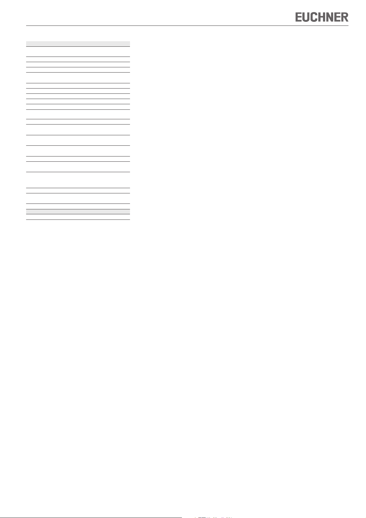
Der Schwenkhebel läßt sich in einem fortlaufenden Raster von 10° umstellen. Je nach Anforderung kann der Hebel mit Rolle zusätzlich nach außen oder nach innen gedreht werden.
Nach Einstellen der gewünschten Anfahrrichtung wird der Schwenkhebel mit der Schraube
befestigt.
Gleichzeitiges Drücken
und Drehen der Scheibe
-90° 0° +90°
Links
schaltend
Links / Rechts
schaltend
(Standardeinstellung)
Drehen des
Betätigungs-
stückes
Rechts
schaltend
Bild 6: Umstellen des Schwenkhebels Bild 7: Umstellen der Schaltrichtung
EUCHNER GmbH + Co. KG Kohlhammerstraße 16 D-70771 Leinfelden-Echterdingen Tel. +49/711/75 97-0 Fax +49/711/75 33 16 www.euchner.de info@euchner.de
Page 3
Betriebsanleitung Sicherheitsschalter NM..HB
Technische Daten
Parameter Wert
Gehäusewerkstoff Glasfaserverstärkter
Schutzart nach IEC 60529 IP67
Mech. Schaltspiele 20x10
Umgebungstemperatur -20 ... +80 °C
Verschmutzungsgrad
(extern, nach EN 60947-1)
Einbaulage beliebig
Anfahrgeschwindigkeit max. 60 m/min
Betätigungskraft bei 20 °C0,1 Nm
Betätigungshäufigkeit max. 5000/h
Schaltprinzip Schleichschaltglied
Kontaktwerkstoff Silberlegierung
Anschlussart Schraubanschluss
Leiterquerschnitt
(starr/flexibel)
Bemessungsstoß-
spannungsfestigkeit
Bemessungsisolationsspannung
Bedingter Kurzschlussstrom 100 A
Schaltspannung min.
bei 10 mA
Gebrauchskategorie nach EN 60947-5-1
AC-15 4 A 230 V
DC-13 4 A 24 V
Schaltstrom min. bei 24 V 1 mA
Kurzschlussschutz (Steuersicherung) nach IEC 60269-1
Konv. thermischer Strom Ith4 A
Zuverlässigkeitswerte nach EN ISO 13849-1
B
10d
Thermoplast
6
3 (Industrie)
hauchvergoldet
2
0,34 mm
... 1,5 mm
= 2,5 kV
U
imp
= 250 V
U
i
12 V
4 A gG
7
2 x 10
2
Page 4
Operating Instructions Safety Switch NM..HB
Correct use
Safety switches of type series NM..HB (lever arm)
are used in control systems that perform safety
functions, e.g. for safety guards or as position
encoders.
The safety switches series NM comply with the
regulations of EN 60947-5-1, Annex K and comply
with the requirements of the employers’ liability
insurance associations for machines, installations and
personnel protection.
Before safety switches are used, a risk assessment
must be performed on the machine in accordance
with
EN ISO 13849-1, Safety of machinery. Safety related
parts of control systems. General principles for
design
EN ISO 14121, Safety of machinery. Risk
assessment. Principles
IEC 62061, Safety of machinery. Functional safety
of safety-related electrical, electronic and
programmable electronic control systems.
Correct use includes compliance with the relevant
requirements for installation and operation, particularly
EN ISO 13849-1, Safety of machinery. Safety related
parts of control systems. General principles for
design
EN 1088, Safety of machinery. Interlocking devices
associated with guards. Principles for design and
selection
EN 60204-1, Electrical equipment of machines
Important:
The user is responsible for the integration of the
device in a safe overall system. For this purpose
the overall system must be validated, e.g. in
accordance with EN ISO 13849-2.
If the simplified method according to section 6.3
EN ISO 13849-1:2008 is used for validation, the
Performance Level (PL) may be reduced if several
devices are connected one after the other.
If a product data sheet is included with the product,
the information on the data sheet applies in case of
discrepancies with the operating instructions.
Safety precautions
Safety switches fulfill a personal protection function.
Incorrect installation or tampering can lead to severe
injuries to personnel.
Safety components must not be bypassed
(bridging of contacts), turned away, removed or
otherwise rendered ineffective.
On this topic pay attention in particular to the
measures for reducing the possibility of bypassing
from EN 1088:1995+A2:2008, section 5.7.
Mounting, electrical connection and setup only
by authorized personnel.
Function
See travel diagram.
Mounting
Safety switches and trip dogs must not be used
as an end stop.
Safety switches and trip dogs must be arranged such
that they are adequately secured against movement.
To meet these requirements:
The fixings must be reliable and must also require
the use of a tool to undo them.
Mount the safety switch positively.
For safety-related applications (fixed positioning),
mount switch with M5x30 screws.
To ensure correct operation, the trip dogs must be fitted
as per the dimension
+1
(see Figure 4 and 5).
41
0
Figure 1: Changing the actuating direction
Protection against environmental influences
A lasting and correct safety function requires that the
actuating head must be protected against the
penetration of foreign bodies such as swarf, sand,
blasting shot, etc.
Cover the actuating head, the trip dog and the rating
plate during painting work!
Only use solvent-free cleaning agents to clean the
safety switch!
Switching elements and switching functions
actuated
21
22
22
21
13
14
31
32
21
22
31
32
21
22
13
14
31
32
21
22
11
12
22
21
11
12
Figure 2: Switching elements and switching functions
Electrical connection
When choosing the insulation material and wire
for the connections, pay attention to the overtemperature in the housing (depending on the
operating conditions)!
For use and applications as per the requirements
of
, a class 2 power supply or a class 2
transformer according to UL1310 or UL1585
must be used. As an alternative, a low voltage
power supply according to UL508 table 32.1
can be used.
A
ActuatedNot
21
22
21
22
13
14
31
32
21
22
32
31
21
22
13
14
32
31
21
22
12
11
22
21
11
12
NM01
NM11,
NM11..C2069
NM02
NM12
NM03
NM02..C2069
M=0,6Nm
Fig. 3: Opening the safety switch
Break out the required entry opening.
Fit cable gland M16 x 1.5 with appropriate degree
of protection.
Conductor cross-section 0.34 mm2 ... 1.5 mm².
For terminal assignment see Figure 2.
Tighten the screws with a torque of 0.5 Nm.
Check that the cable entry is sealed.
Close the cover and screw in position.
Functional check
When the safety guard is open, the safety switch
must be actuated in any safety guard position
(overrun protection).
In safety circuits, check the safety function.
The machine must stop when the safety switch is
actuated.
The machine must not start when the safety switch
is actuated.
Mechanical function test
Check the actuating element for freedom of
movement.
Electrical function test
Actuate switch and check the switching function.
Inspection and service
If damage or wear is found, the complete switch
and actuator assembly must be replaced.
Replacement of individual parts or assemblies
is not permitted!
No servicing is required, but regular inspection of
the following is necessary to ensure trouble-free longterm operation:
correct switching function
secure mounting of components
dirt and wear
sealing of cable entry
loose cable connections or plug connectors.
Note:The year of manufacture can be seen in the
bottom, right corner of the rating plate.
Page 5

Operating Instructions Safety Switch NM..HB
46
8
32
25
12,5
Dog
0
+1
41
1,5
128,5
∅5
∅4,2
16,5
16
12,5
32
M16x1,5
C
M=0,6Nm
B
NM03
NM02
R
6
25
27
*
17
M=1 Nm
18
M=0,6Nm
25
M16x1,5
D
M=0,6Nm
A
Standard
0°
11-12
21-22
31-32
*fixed positioning for safety-
35°
60°
6
5°
related applications (M5)
Figure 4: Dimension drawing NM11HB / NM02HB / NM12HB / NM03HB
46
8
32
25
12,5
97,5
NM01
1,5
∅5
∅4,2
M=0,6Nm
0˚
21-22
0
+1
41
16,5
35˚
Dog
R6
25
27
*
17
60˚
65˚
M=1 Nm
NM02
(C2069)
(C2069)
18
NM12
NM11
NM11
21-22
31-32
13-14
21-22
Exclusion of liability under the following
13-14
21-22
31-32
0°
35°
45
°
60
°
6
5
°
circumstances
incorrect use
non-compliance with safety regulations
installation and electrical connection not performed
by authorized personnel.
failure to perform functional checks.
EC declaration of conformity
The manufacturer named below herewith declares that
the product fulfills the provisions of the directive(s)
listed below and that the related standards have been
applied.
EUCHNER GmbH + Co. KG
Kohlhammerstraße 16
70771 Leinfelden-Echterdingen, Germany
Directives applied:
Machinery directive 2006/42/EC
Standards applied:
EN 60947-5-1:2004 + Cor.:2005 + A1:2009
EN 1088:1995+A2:2008
Leinfelden, July 2010
Dipl.-Ing. Michael Euchner
Director
Duc Binh Nguyen
Authorized representative empowered to draw up
0˚
35˚
60˚
65˚
0˚
35˚
45˚
60
˚
65˚
documentation
The signed EC declaration of conformity is included
with the product.
M16x1,5
*fixed positioning for safety-related applications
(M5)
32
C
M=0,6Nm
B
25
D
M=0,6Nm
A
Standard
Figure 5: Dimension drawing NM01HB, NM...C2069
The lever arm can be adjusted to positions every 10°. Depending on the application, the
lever with roller can also be rotated to the outside or the inside. After setting the required
approach direction, the lever arm is fastened using the screw.
Simultaneously press
and rotate the washer
-90° 0° +90°
Rotate the
actuating
Subject to technical modifications; no responsibility is accepted for the accuracy of this information. © EUCHNER GmbH + Co. KG 084462-04-11/10 (translation of the original operating instructions)
element
Left
switching
Left / right
switching
(default setting)
Right
switching
Figure 6: Changing the lever arm Figure 7: Changing the switching direction
EUCHNER GmbH + Co. KG Kohlhammerstraße 16 D-70771 Leinfelden-Echterdingen Tel. +49/711/75 97-0 Fax +49/711/75 33 16 www.euchner.de info@euchner.de
Page 6

Operating Instructions Safety Switch NM..HB
Technical data
Parameters Value
Housing material Reinforced
Degree of protection
acc. to IEC 60529
Mechanical operating cycles 20x10
Ambient temperature -20 ... +80 °C
Degree of contamination
(external, acc. to EN 60947-1)
Installation position Any
Approach speed, max. 60 m/min
Actuating force at 20 °C0.1 Nm
Actuation frequency, max. 5000 / h
Switching principle Slow-action switching contact
Contact material Silver alloy
Connection type Screw terminal
Conductor cross-section
(rigid/flexible)
Rated impulse
withstand voltage
Rated
insulation voltage
Rated short-circuit current 100 A
Switching voltage min.
at 10 mA
Utilization category to EN 60947-5-1
AC-15 4 A 230 V
DC-13 4 A 24 V
Switching current,
min., at 24 V
Short circuit protection (control
circuit fuse) acc. to IEC 60269-1
Conv. thermal current Ith4 A
Reliability figures according to EN ISO 13849-1
B
10d
thermoplastic
IP67
6
3 (industrial)
gold flashed
2
0.34 mm
... 1.5 mm
= 2.5 kV
U
imp
= 250 V
U
i
12 V
1 mA
4 A gG
7
2 x 10
2
Page 7

Mode d’emploi pour les interrupteurs de sécurité NM..HB
Utilisation conforme
Les interrupteurs de sécurité de la série NM..HB (levier
à galet) sont utilisés comme composants de systèmes
de commande qui remplissent des fonctions de
sécurité (notamment pour des protecteurs ou en tant
qu’indicateurs de position).
Les interrupteurs de sécurité de la série NM répondent
aux prescriptions EN 60947-5-1 Annexe K et satisfont
aux exigences des organismes professionnels
concernant les machines, les installations et la
protection des personnes.
Avant d’utiliser des interrupteurs de sécurité, il est
nécessaire d’effectuer une analyse d’appréciation du
risque sur la machine selon
EN ISO 13849-1, Parties des systèmes de
commande relatives à la sécurité
EN ISO 14121, Sécurité des machines, appréciation
du risque
IEC 62061, Sécurité des machines - Sécurité
fonctionnelle des systèmes de commande
électriques, électroniques et électroniques
programmables relatifs à la sécurité.
Pour que l’utilisation soit conforme, les instructions
applicables au montage et à la mise en service doivent
être respectées, en particulier
EN ISO 13849-1, Parties des systèmes de
commande relatives à la sécurité
EN 1088, Dispositifs de verrouillage associés à des
protecteurs
EN 60204-1, Equipement électrique des machines.
Important :
L’utilisateur est responsable de l’intégration de
l’appareil dans un système global sécurisé. Ce
dernier doit être validé à cet effet, par ex. selon
EN ISO 13849-2.
Si la validation fait appel à la procédure simplifiée
selon le paragraphe 6.3 EN ISO 13849-1:2008, le
niveau de performance ou Performance Level (PL)
peut diminuer lorsque plusieurs appareils sont
raccordés en série l’un à la suite de l’autre.
Si le produit est accompagné d’une fiche technique,
les indications de cette dernière prévalent en cas
de différences avec les indications figurant dans le
mode d’emploi.
Consignes de sécurité
Les interrupteurs de sécurité remplissent une
fonction de protection des personnes. Le montage
ou les manipulations non conformes peuvent
engendrer de graves blessures.
Les éléments de sécurité ne doivent pas être
contournés (pontage des contacts), déplacés,
retirés ou être inactivés de quelque manière que
ce soit.
Tenez compte en particulier des mesures de
réduction des possibilités de fraude selon
EN 1088:1995+A2:2008, paragr. 5.7.
Montage, raccordement électrique et mise en
service exclusivement par un personnel habilité.
Fonction
Voir diagramme de commutation
Montage
Les interrupteurs de sécurité et les cames ne
doivent pas être utilisés comme butée.
Les interrupteurs de sécurité et les cames doivent
être disposés de manière à éviter toute modification
involontaire de leur position.
Pour remplir ces conditions :
Les éléments de fixation doivent être fiables et leur
dévissage ne doit pouvoir être effectué qu’à l’aide
d’un outil.
Figure 1 : Changement de la direction d’actionnement
Fixer l’interrupteur de sécurité de façon permanente.
Pour les applications de sécurité (positionnement
fixe), monter l’interrupteur à l’aide de vis M5x30.
Afin d’assurer un fonctionnement normal, les cames
de commande doivent être fixées conformément aux
dimensions
+1
(voir figures 4 et 5).
41
0
Protection contre les influences ambiantes
La condition pour garantir une fonction de sécurité
durable et parfaite est de protéger la tête
d’actionnement contre la pénétration de corps
étrangers (ex. : copeaux, sable, grenailles, etc.).
En cas de laquage, couvrir la tête d’actionnement, la
came et la plaque signalétique !
Pour le nettoyage des interrupteurs de sécurité,
utiliser uniquement des produits de nettoyage
exempts de solvants !
Eléments de commutation et fonctions de
commutation
actionné
21
22
22
21
13
14
31
32
21
22
31
32
21
22
13
14
31
32
21
22
11
12
22
21
11
12
Figure 2 : Eléments de commutation et fonctions de
commutation
Raccordement électrique
Tenir compte, pour le choix du matériau isolant
ou des conducteurs, de la température élevée
régnant à l’intérieur du boîtier (selon les
conditions de fonctionnement) !
Pour que l’utilisation soit conforme aux exigences
de , une alimentation ou un transformateur
de classe 2 doit être utilisé conformément à
UL1310 ou UL1585. Une source d’alimentation
basse tension conforme à la norme UL508 Tableau 32.1 peut également être utilisée.
A
Figure 3 :Ouverture de l’interrupteur de sécurité
Percer l’ouverture du presse-étoupe souhaitée.
Monter le presse-étoupe M16 x 1,5 avec le type
de protection correspondant.
Section de conducteur 0,34 mm2 ... 1,5 mm².
Pour l’affectation des contacts, voir fig. 2.
Serrer les vis de connexion au couple de 0,5 Nm.
Veiller à l’étanchéité à l’entrée du câble.
ActionnéNon
21
22
NM01
21
22
13
31
21
31
21
13
31
21
11
21
11
NM11,
NM11..C2069
14
32
NM02
22
NM12
32
22
14
NM03
32
22
12
NM02..C2069
22
12
Fermer le couvercle de l’interrupteur et le visser.
Contrôle fonctionnel
Lorsque le protecteur est ouvert, l’interrupteur
de sécurité doit être actionné dans chacune des
positions du protecteur (protection contre les
dépassements).
Contrôler la fonction de sécurité dans les circuits
de sécurité.
La machine doit s’arrêter lorsque l’interrupteur
de sécurité est actionné.
La machine ne doit pas démarrer lorsque
l’interrupteur de sécurité est actionné.
Contrôle du fonctionnement mécanique
Contrôler la mobilité de l’élément d’actionnement.
Contrôle du fonctionnement électrique
Actionner l’interrupteur et contrôler la fonction de
commutation.
Contrôle et entretien
En cas d’endommagement ou d’usure, il est
nécessaire de remplacer entièrement l’interrupteur
avec l’élément d’actionnement.
Le remplacement de composants ou de sousensembles n’est pas autorisé !
Aucun entretien n’est nécessaire. Pour garantir un
fonctionnement irréprochable et durable, il convient
toutefois de vérifier régulièrement les points suivants :
Fonction de commutation correcte
Bonne fixation des composants
Dépôts et usure
Étanchéité à l’entrée du câble
Serrage des connexions ou connecteurs.
Remarque : l’année de construction figure dans le
coin inférieur droit de la plaque signalétique.
M=0,6Nm
Page 8

Mode d’emploi pour les interrupteurs de sécurité NM..HB
46
8
32
25
12,5
Came
0
+1
41
1,5
128,5
∅5
∅4,2
16,5
16
12,5
32
M16x1,5
C
M=0,6Nm
B
NM03
NM02
R
6
25
27
*
17
M=1 Nm
18
M=0,6Nm
25
M16x1,5
D
M=0,6Nm
A
Standard
0°
11-12
21-22
31-32
*Positionnement fixe
35°
pour des applications
de sécurité (M5)
Figure 4 : Dimensions NM11HB / NM02HB / NM12HB / NM03HB
46
8
32
25
12,5
97,5
NM01
1,5
∅5
∅4,2
M=0,6Nm
0˚
21-22
0
+1
41
16,5
35˚
Came
R6
25
M=1 Nm
27
*
17
18
Nous déclinons toute responsabilité
0°
13-14
21-22
31-32
35°
45
°
60
°
6
5
°
NM11
NM12
60°
6
5°
en cas d’utilisation non conforme ;
en cas de non-respect des consignes de sécurité ;
si le montage et le raccordement électrique sont
effectués par du personnel non agréé.
si les contrôles fonctionnels ne sont pas effectués.
Déclaration de conformité CE
Le fabricant ci-dessous déclare par la présente que
le produit est conforme aux dispositions de la ou des
directive(s) précisées ci-après ainsi qu’aux normes
qui lui sont applicables.
EUCHNER GmbH + Co. KG
Kohlhammerstraße 16
D-70771 Leinfelden-Echterdingen, Allemagne
Directives utilisées :
Directive Machines 2006/42/CE
Normes utilisées :
EN 60947-5-1:2004 + Cor.:2005 + A1:2009
EN 1088:1995+A2:2008
Leinfelden, juillet 2010
Dipl.-Ing. Michael Euchner
Directeur Général
Duc Binh Nguyen
Responsable documentation
La déclaration de conformité CE signée est jointe au
0˚
21-22
NM02
(C2069)
NM11
(C2069)
31-32
13-14
21-22
60˚
65˚
35˚
60˚
65˚
0˚
35˚
45˚
60
˚
65˚
produit.
Sous réserve de modifications techniques, indications non contractuelles. © EUCHNER GmbH + Co. KG 084462-04-11/10 (trad. mode d’emploi d’origine)
M16x1,5
*Positionnement fixe pour des applications de
sécurité (M5)
32
C
M=0,6Nm
B
25
D
M=0,6Nm
A
Standard
Figure 5 : Dimensions NM01HB, NM...C2069
Le levier à galet peut être déplacé en continu par incrément de 10°. Selon les exigences, le
levier à galet peut en outre être tourné vers l’intérieur ou l’extérieur. Après le réglage du sens
d’attaque souhaité, le levier à galet est fixé à l’aide de la vis.
Appuyer
et tourner simultanément le
disque
-90° 0° +90°
Pivoter la pièce
de commande
Commutation à
gauche
Commutation à gauche
/ à droite
(réglage standard)
Commutation à
droite
Figure 6 : Changement de position du levier à galet Figure 7 : Changement de la direction d’actionnement
EUCHNER GmbH + Co. KG Kohlhammerstraße 16 D-70771 Leinfelden-Echterdingen Tél. +49/711/75 97-0 Fax +49/711/75 33 16 www.euchner.de info@euchner.de
Page 9

Mode d’emploi pour les interrupteurs de sécurité NM..HB
Caractéristiques techniques
Paramètre Valeur
Matériau du boîtier Thermoplastique renforcé
Indice de protection
selon IEC 60529
Manœuvres mécaniques 20x10
Température ambiante -20 ... +80 °C
Degré de pollution
(externe, selon EN 60947-1)
Position de montage Au choix
Vitesse d’attaque max. 60 m/min
Force d’insertion à 20 °C0,1 Nm
Fréquence d’actionnement maxi. 5000/h
Principe de commutation Élément de contact à action
Matériau des contacts Alliage argent
Type de raccordement Connecteur à vis
Section de conducteur
(rigide/flexible)
Tension nominale
d’essai (impulsion)
Tension nominale
d’isolement
Courant conditionnel
de court-circuit
Tension de commutation min.
à 10 mA
Catégorie d’emploi selon EN 60947-5-1
AC-15 4 A 230 V
DC-13 4 A 24 V
Pouvoir de coupure min. à 24 V 1 mA
Protection contre cc
(fusible de commande) 4 A gG
selon IEC 60269-1
Courant thermique conv. Ith4 A
Valeurs de fiabilité selon EN ISO 13849-1
B
10d
avec des fibres de verre
IP67
6
3 (industrie)
dépendante
doré par soufflage
2
0,34 mm
... 1,5 mm
= 2,5 kV
U
imp
= 250 V
U
i
100 A
12 V
7
2 x 10
2
Page 10

Istruzioni di impiego dei finecorsa di sicurezza NM..HB
Impiego conforme alla destinazione d’uso
I finecorsa di sicurezza della serie NM..HB (leva
girevole) vengono impiegati come parti dei sistemi di
controllo con funzioni di sicurezza, ad esempio per
ripari di protezione o come indicatori di posizione.
I finecorsa di sicurezza della serie NM sono
conformi alle prescrizioni dell’allegato K della norma
EN 60947-5-1 e ai requisiti previsti dagli istituti di
assicurazione contro gli infortuni sul lavoro per
macchine, impianti e protezione delle persone.
Prima di impiegare i finecorsa di sicurezza, la
macchina deve essere stata oggetto di una
valutazione del rischio, conformemente alle norme:
EN ISO 13849-1, Parti dei sistemi di comando legate
alla sicurezza
EN ISO 14121, Sicurezza del macchinario,
Valutazione del rischio
IEC 62061, Sicurezza del macchinario – Sicurezza
funzionale dei sistemi di comando e controllo
elettrici, elettronici ed elettronici programmabili
correlati alla sicurezza.
L’impiego conforme alla destinazione d’uso implica il
rispetto delle vigenti norme relative all’installazione e
all’esercizio, in particolare
EN ISO 13849-1, Parti dei sistemi di comando legate
alla sicurezza
EN 1088, Dispositivi di interblocco associati ai ripari
EN 60204-1, Equipaggiamento elettrico delle
macchine.
Importante:
L’utente è responsabile per l’integrazione del
dispositivo in un sistema generale sicuro. A questo
scopo, il sistema generale deve essere validato p.
es. secondo la EN ISO 13849-2.
Se per la validazione si ricorre alla procedura
semplificata secondo la sezione 6.3 della EN ISO
13849:2008, si ridurrà eventualmente il Performance Level (PL) se vengono collegati in serie più
dispositivi.
Se al prodotto è allegata una scheda tecnica,
valgono le indicazioni della stessa, qualora fossero
diverse da quanto riportato nelle istruzioni di
impiego.
Avvertenze di sicurezza
I finecorsa di sicurezza svolgono una funzione di
protezione delle persone. Un’installazione inadeguata
o eventuali manomissioni possono causare gravi
lesioni alle persone.
I componenti di sicurezza non devono essere
né aggirati (ponticellando i contatti), né rimossi,
né girati, né resi inefficaci in altra maniera.
Osservare in proposito le misure per la riduzione
delle possibilità di manomissione secondo la EN
1088:1995+A2:2008, sezione 5.7.
L’installazione, il collegamento elettrico e la messa
in servizio sono da affidare esclusivamente al personale specializzato e autorizzato.
Funzionamento
Vedere diagramma di funzionamento.
Installazione
Il finecorsa di sicurezza e le camme non devono
essere utilizzati come riscontro meccanico di
arresto.
I finecorsa di sicurezza e le camme devono essere
installati in modo che non siano possibili variazioni
della posizione.
Per soddisfare questi requisiti:
Gli elementi di fissaggio devono essere sicuri e
richiedere un apposito attrezzo per essere rimossi.
Montare il finecorsa di sicurezza con un corretto
accoppiamento meccanico.
Fig. 1: Modifica della direzione di azionamento
Per applicazioni rilevanti ai fini della sicurezza
(posizionamento fissato), montare gli interruttori con
viti M5x30.
Per assicurare il funzionamento regolare, le camme
devono essere montate secondo la dimensione
(vedi figure 4 e 5).
Protezione contro gli agenti ambientali
Premessa necessaria per un corretto e durevole
funzionamento in sicurezza è che nella testina di
azionamento non entrino corpi estranei quali trucioli,
sabbia, graniglia, ecc.
Prima dei lavori di verniciatura coprire la testina di
azionamento, le camme e l’etichetta di identificazione!
Per la pulizia dei finecorsa di sicurezza, utilizzare
esclusivamente detergenti privi di solventi!
Microinterruttori e commutazioni
azionato
21
22
22
21
13
14
31
32
21
22
31
32
21
22
13
14
31
32
21
22
11
12
22
21
11
12
Fig. 2: Microinterruttori e commutazioni
Collegamento elettrico
Nella scelta del materiale isolante o dei cavi
di collegamento, prestare attenzione alla
sovratemperatura presente nella custodia
(dipendente dalle condizioni di funzionamento)!
Per l’impiego e l’utilizzo in conformità ai requisiti
si deve utilizzare un’alimentazione classe 2 o
un trasformatore classe 2 conforme a UL1310 o
UL1585. In alternativa utilizzare un’alimentazione a
bassissima tensione secondo UL508 Tabella 32.1.
A
+1
41
0
Fig. 3: Apertura del finecorsa di sicurezza
AzionatoNon
21
22
NM01
21
22
13
31
21
31
21
13
31
21
11
21
11
NM11,
NM11..C2069
14
32
NM02
22
NM12
32
22
14
NM03
32
22
12
NM02..C2069
22
12
Controllo funzionale
Prova della funzione meccanica
Verificare il movimento scorrevole dell’elemento
azionatore.
Prova della funzione elettrica
Azionare il finecorsa e verificare la funzione di
commutazione.
Controllo e manutenzione
Non sono necessari interventi di manutenzione. Per
garantire un funzionamento corretto e durevole si
consiglia comunque di controllare regolarmente
Nota: l’anno di costruzione si trova sull’angolo destro
in basso della targhetta di identificazione.
M=0,6Nm
Rompere l’apertura di inserimento desiderata.
Montare il pressacavo M16 x 1,5 con grado di
protezione idoneo.
Sezione del conduttore 0,34 mm2 ... 1,5 mm².
Disposizione dei contatti: vedere fig. 2.
Serrare le viti di arresto con 0,5 Nm.
Accertarsi che il pressacavo sia a tenuta.
Chiudere ed avvitare il coperchio del finecorsa.
Con il riparo di protezione aperto, il finecorsa di
sicurezza deve risultare azionato in qualsiasi
posizione del riparo (protezione di spostamento).
Nei circuiti di sicurezza verificare la funzione di
sicurezza.
La macchina deve fermarsi all’azionamento del
finecorsa di sicurezza.
La macchina non deve avviarsi con il finecorsa
azionato.
In caso di danneggiamenti o di usura si deve
sostituire il finecorsa completo, incluso l’azionatore.
Non è ammessa la sostituzione di singoli
componenti o di blocchi!
la corretta commutazione
il fissaggio dei singoli componenti
l’eventuale presenza di depositi o segni d’usura
la tenuta dell’ingresso del cavo
l’eventuale allentarsi dei cavi di collegamento o dei
connettori.
Page 11

Istruzioni di impiego dei finecorsa di sicurezza NM..HB
46
8
32
25
12,5
Camma
0
+1
41
1,5
128,5
∅5
∅4,2
16,5
16
12,5
32
M16x1,5
C
M=0,6Nm
B
NM03
NM02
R
6
25
27
*
17
M=1 Nm
18
M=0,6Nm
25
M16x1,5
D
M=0,6Nm
A
Standard
0°
11-12
21-22
31-32
*Posizionamento fissato per
applicazioni di sicurezza
(M5)
Fig. 4: Dimensioni NM11HB / NM02HB / NM12HB / NM03HB
46
8
32
25
12,5
97,5
NM01
1,5
∅5
∅4,2
M=0,6Nm
0˚
21-22
Camma
R6
0
+1
41
*
17
16,5
18
35˚
25
27
35°
60˚
65˚
M=1 Nm
60°
6
5°
NM12
NM02
(C2069)
NM11
(C2069)
NM11
21-22
31-32
13-14
21-22
Esclusione di responsabilità in caso di
13-14
21-22
31-32
0°
35°
45
°
60
°
6
5
°
impiego non conforme alla destinazione d’uso
mancato rispetto delle istruzioni di sicurezza
montaggio e collegamento elettrico non eseguiti
da personale specializzato e autorizzato
omissione delle prove funzionali.
Dichiarazione CE di conformità
Il fabbricante indicato di seguito dichiara che il
prodotto è conforme alle disposizioni della/delle
direttiva/e sottoelencata/e e che sono state applicate
le norme pertinenti.
EUCHNER GmbH + Co. KG
Kohlhammerstraße 16
70771 Leinfelden-Echterdingen, Germania
Direttive applicate:
Direttiva Macchine 2006/42/CE
Norme applicate:
EN 60947-5-1:2004 + Cor.:2005 + A1:2009
EN 1088:1995+A2:2008
Leinfelden, luglio 2010
Dipl. Ing. Michael Euchner
Amministratore delegato
Duc Binh Nguyen
Responsabile della documentazione
La dichiarazione CE di conformità firmata è allegata
0˚
35˚
60˚
65˚
0˚
35˚
45˚
60
˚
65˚
al prodotto.
M16x1,5
*Posizionamento fissato per applicazioni di
sicurezza (M5)
32
C
M=0,6Nm
B
25
D
M=0,6Nm
A
Standard
Fig. 5: Dimensioni NM01HB, NM...C2069
La posizione della leva girevole può essere modificata in continuo di 10°. A seconda delle
esigenze, la leva con la rotella può essere ulteriormente ruotata verso l’esterno o verso
l’interno. Dopo la regolazione della direzione di azionamento desiderata la leva girevole deve
venire fissata con la vite.
Pressione
e rotazione contemporanea
della rondella
-90° 0° +90°
Commutazione
a sinistra.
Commutazione
destra/sinistra.
(impostazione standard)
Rotazione
dell’elemento di
azionamento
Commutazione
a
destra.
Con riserva di modifiche tecniche, tutti i dati sono soggetti a modifiche. © EUCHNER GmbH + Co. KG 084462-04-11/10 (Traduzione delle istruzioni di impiego originali)
Fig. 6: Modifica della posizione della leva girevole Fig. 7: Modifica della direzione di commutazione
EUCHNER GmbH + Co. KG Kohlhammerstraße 16 D-70771 Leinfelden-Echterdingen Tel. +49/711/75 97-0 Fax +49/711/75 33 16 www.euchner.de info@euchner.de
Page 12

Istruzioni di impiego dei finecorsa di sicurezza NM..HB
Dati tecnici
Parametri Valore
Materiale custodia termoplastica rinforzata
Grado di protezione
sec. IEC 60529
Manovre mecc. 20x10
Temperatura ambiente -20 ... +80 °C
Grado di inquinamento
(esterno, secondo EN 60947-1)
Posizione di installazione qualsiasi
Velocità di avvicinamento max. 60 m/min
Forza di azionamento a 20°C0,1 Nm
Frequenza di azionamento max. 5000/h
Principio di commutazione microinterruttore ad azione lenta
Materiale dei contatti lega di argento
Tipo di collegamento collegamento a vite
Sezione conduttori
(rigido/flessibile)
Rigidità dielettrica
nominale
Tensione di
isolamento nominale
Corrente di cortocircuito
condizionata
Tensione di commutazione
min. a 10 mA
Categoria d’impiego secondo EN 60947-5-1
AC-15 4 A 230 V
DC-13 4 A 24 V
Corrente di commutazione
min. a 24 V
Protezione contro cortocircuiti
(fusibile di comando) 4 A gG
secondo IEC 60269-1
Corrente continua termica
standard I
th
Valori di affidabilità secondo EN ISO 13849-1
B
10d
con fibra di vetro
IP67
6
3 (industria)
placcata oro
2
0,34 mm
... 1,5 mm
= 2,5 kV
U
imp
= 250 V
U
i
100 A
12 V
1 mA
4 A
7
2 x 10
2
 Loading...