

Page 1

Betriebsanleitung
12
-0,5
Präzisions-Einzelgrenztaster N1A
Bestimmungsgemäßer Gebrauch
Präzision-Einzelgrenztaster der Baureihe N1A sind
Verriegelungseinrichtungen ohne Zuhaltung (Bauart 1). Der Betätiger ist uncodiert (z. B. Nocken).
In Verbindung mit einer beweglichen trennenden
Schutzeinrichtung und der Maschinensteuerung
verhindert dieses Sicherheitsbauteil, dass gefährliche
Maschinenfunktionen ausgeführt werden, solange die
Schutzeinrichtung geöffnet ist. Wenn die Schutzeinrichtung während der gefährlichen Maschinenfunktion
geöffnet wird, wird ein Stoppbefehl ausgelöst.
Für allgemeine Anwendungen werden Sprungschaltelemente ES502E eingesetzt. Für die Verwendung
als Sicherheitsschalter sind nur die Schaltelemente
ES508E, ES514 und ES588 mit zwangsgeführten
Öffnern zulässig.
Das bedeutet:
Einschaltbefehle, die eine gefährliche Maschinen-
funktion hervorrufen, dürfen erst dann wirksam werden, wenn die Schutzeinrichtung geschlossen ist.
Das Öffnen der Schutzeinrichtung löst einen Stopp-
befehl aus.
Das Schließen einer Schutzeinrichtung darf kein
selbstständiges Anlaufen einer gefährlichen Maschinenfunktion hervorrufen. Hierzu muss ein separater
Startbefehl erfolgen. Ausnahmen hierzu siehe
ENISO12100 oder relevante C-Normen
Geräte dieser Baureihe können als sichere Positionsgeber eingesetzt werden.
Vor dem Einsatz des Geräts ist eine Risikobeurteilung
an der Maschine durchzuführen z.B. nach folgenden
Normen:
ENISO13849-1, Sicherheitsbezogene Teile von
Steuerungen
ENISO12100, Sicherheit von Maschinen - All-
gemeine Gestaltungsleitsätze - Risikobeurteilung
und Risikominderung
IEC62061, Sicherheit von Maschinen – Funktionale
Sicherheit sicherheitsbezogener elektrischer, elektronischer und programmierbarer elektronischer
Steuerungssysteme.
Zum bestimmungsgemäßen Gebrauch gehört das
Einhalten der einschlägigen Anforderungen für den
Einbau und Betrieb, insbesondere nach folgenden
Normen:
ENISO13849-1, Sicherheitsbezogene Teile von
Steuerungen
ENISO14119, Verriegelungseinrichtungen in
Verbindung mit trennenden Schutzeinrichtungen
EN60204-1, Elektrische Ausrüstung von Maschi-
nen.
Wichtig!
Der Anwender trägt die Verantwortung für die
korrekte Einbindung des Geräts in ein sicheres
Gesamtsystem. Dazu muss das Gesamtsystem
z.B. nach ENISO13849-2 validiert werden.
Wird zur Bestimmung des Perfomance Le-
vels (PL) das vereinfachte Verfahren nach
ENISO13849-1:2015, Abschnitt 6.3 benutzt,
reduziert sich möglicherweise der PL, wenn
mehrere Geräte hintereinander geschaltet werden.
Eine logische Reihenschaltung sicherer Kontakte
ist unter Umständen bis zu PLd möglich. Nähere
Informationen hierzu gibt ISOTR24119.
Liegt dem Produkt ein Datenblatt bei, gelten die
Angaben des Datenblatts, falls diese von der
Betriebsanleitung abweichen.
Sicherheitshinweise
WARNUNG
Lebensgefahr durch unsachgemäßen Einbau oder
Umgehen (Manipulation). Sicherheitsbauteile erfüllen
eine Personenschutz-Funktion.
Sicherheitsbauteile dürfen nicht überbrückt,
weggedreht, entfernt oder auf andere Weise
unwirksam gemacht werden. Beachten Sie
hierzu insbesondere die Maßnahmen zur Verringerung der Umgehungsmöglichkeiten nach
ENISO14119:2013, Abschn. 7.
Montage, elektrischer Anschluss und Inbetriebnah-
me ausschließlich durch autorisiertes Fachpersonal, welches über spezielle Kenntnisse im Umgang
mit Sicherheitsbauteilen verfügt.
Funktion
Präzisions-Einzelgrenztaster werden zum Positionieren und Steuern im Maschinen- und Anlagenbau
eingesetzt.
Die Schaltelemente werden über Stößel betätigt. Entsprechend der Anwendung (Schaltpunktgenauigkeit
und Anfahrgeschwindigkeit) werden verschiedene
Stößel und Steuernocken eingesetzt (siehe Bild 4).
Das Betätigen der Stößel erfolgt bei allgemeiner
Anwendung durch Steuernocken nach DIN 69639,
die in Nutenprolen nach DIN 69638 kraftschlüssig
befestigt sind.
Beim Bewegen des Betätigungselements aus der
Ruhestellung in die Endstellung werden die Schaltkontakte betätigt. Die Sicherheitskontakte werden
dabei zwangsweise geöffnet (siehe Bild 2).
Schaltzustände
Die detaillierten Schaltzustände für Ihren Schalter
nden Sie in Bild 2. Dort sind alle verfügbaren Schaltelemente beschrieben.
Betätigungselement in Ruhestellung
Die Sicherheitskontakte sind geschlossen.
Betätigungselement in Endstellung
Die Sicherheitskontakte sind geöffnet.
Montage
HINWEIS
Geräteschäden durch falschen Anbau und ungeeignete Umgebungsbedingungen
Sicherheitsschalter und Betätiger dürfen nicht als
Anschlag verwendet werden.
Beachten Sie ENISO14119:2013, Abschnitte 5.2
und 5.3, zur Befestigung des Sicherheitsschalters
und des Betätigers.
Beachten Sie ENISO14119:2013, Abschnitt 7,
zur Verringerung von Umgehungsmöglichkeiten
einer Verriegelungseinrichtung.
In Sicherheitsschaltkreisen Maß
(Abstand
Bezugsäche des Schalters zu Steuernocken,
siehe Bild 6) zur sicheren Kontaktöffnung unbedingt einhalten.
Schützen Sie den Schalter vor Beschädigung.
Schutz vor Umgebungseinüssen
Entlüftungsventile (siehe Bild 7) dienen dem Druckausgleich gegen Pumpwirkung der Stößel. Sie dürfen
nicht mit Farbe verschlossen werden.
Bei Lackierarbeiten Stößel, Stößelführung, Entlüf-
tungsventile und Typenschild abdecken!
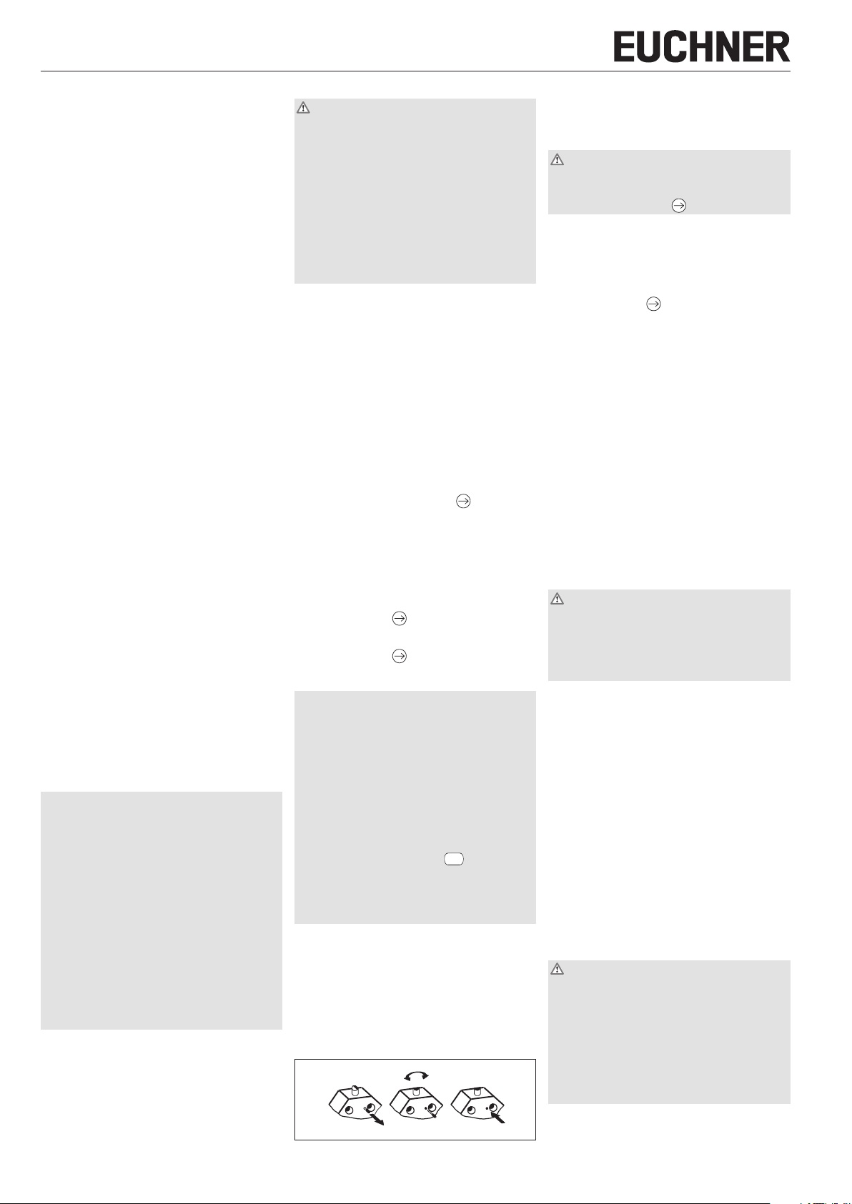
Umstellen der Betätigungsrichtung
90°
Bild 1: Umstellen der Betätigungsrichtung
1. Arretierschraube herausschrauben.
2. Gewünschte Richtung einstellen.
3. Arretierschraube wieder einschrauben.
Elektrischer Anschluss
WARNUNG
Verlust der Sicherheitsfunktion durch falschen
Anschluss.
Für Sicherheitsfunktionen nur sichere Kontakte
( ) verwenden.
Bei Verwendung von nachrüstbaren Anzeigeleuchten
ist der auf dem Gehäuse der Anzeigeleuchte aufgedruckte Spannungsbereich einzuhalten (Anschluss
siehe Bild 2).
Anwendung des Sicherheitsschalters als
Verriegelung für den Personenschutz
Es muss mindestens ein Kontakt verwendet
werden. Dieser signalisiert die Stellung der Schutzeinrichtung (Kontaktbelegung siehe Bild 2).
Für Geräte mit Steckverbinder gilt:
Auf Dichtheit des Steckverbinders achten.
Für Geräte mit Leitungseinführung gilt:
1. Gewünschte Einführöffnung mit geeignetem
Werkzeug öffnen.
2. Kabelverschraubung mit entsprechender
Schutzart montieren.
3. Anschließen und Klemmen anziehen (Kontaktbelegung siehe Bild 2, Anzugsdrehmomente siehe
technische Daten).
4. Auf Dichtheit der Leitungseinführung achten.
5. Schalterdeckel schließen und verschrauben
(Anzugsdrehmoment 0,5Nm).
Funktionsprüfung
WARNUNG
Tödliche Verletzung durch Fehler bei der Funktionsprüfung.
Stellen Sie vor der Funktionsprüfung sicher, dass
sich keine Personen im Gefahrenbereich benden.
Beachten Sie die geltenden Vorschriften zur
Unfallverhütung.
Überprüfen Sie nach der Installation und nach jedem
Fehler die korrekte Funktion des Geräts.
Gehen Sie dabei folgendermaßen vor:
Mechanische Funktionsprüfung
Das Betätigungselement muss sich leicht bewegen
lassen. Zur Prüfung Schutzeinrichtung mehrmals
schließen.
Elektrische Funktionsprüfung
1. Betriebsspannung einschalten.
2. Alle Schutzeinrichtungen schließen.
Die Maschine darf nicht selbständig anlaufen.
3. Maschinenfunktion starten.
4. Schutzeinrichtung öffnen.
Die Maschine muss abschalten und darf sich nicht
starten lassen, solange die Schutzeinrichtung
geöffnet ist.
Wiederholen Sie die Schritte 2 - 4 für jede Schutzeinrichtung einzeln.
Kontrolle und Wartung
WARNUNG
Gefahr von schweren Verletzungen durch den Verlust
der Sicherheitsfunktion.
In Sicherheitsschaltkreisen muss bei Beschädi-
gung oder Verschleiß der gesamte Schalter ausgetauscht werden. Der Austausch von Einzelteilen
oder Baugruppen ist nicht zulässig.
Überprüfen Sie in regelmäßigen Abständen und
nach jedem Fehler die korrekte Funktion des Geräts. Hinweise zu möglichen Zeitintervallen entnehmen Sie der ENISO14119:2013, Abschnitt 8.2.
1
Page 2

Betriebsanleitung
Präzisions-Einzelgrenztaster N1A
Um eine einwandfreie und dauerhafte Funktion zu
gewährleisten, sind folgende Kontrollen erforderlich:
einwandfreie Schaltfunktion
sichere Befestigung aller Bauteile
präzise Justierung von Steuernocken zu Einzel-
grenztaster
Beschädigungen, starke Verschmutzung, Ablage-
rungen und Verschleiß
Dichtheit der Kabeleinführung
gelockerte Leitungsanschlüsse bzw. Steckver-
binder.
Info: Das Baujahr ist in der unteren, rechten Ecke des
Typschilds ersichtlich.
Haftungsausschluss und
Gewährleistung
Wenn die o. g. Bedingungen für den bestimmungsgemäßen Gebrauch nicht eingehalten werden oder wenn
die Sicherheitshinweise nicht befolgt werden oder
wenn etwaige Wartungsarbeiten nicht wie gefordert
durchgeführt werden, führt dies zu einem Haftungsausschluss und dem Verlust der Gewährleistung.
Hinweise zu
Für Geräte mit Leitungseinführung gilt:
Für den Einsatz und die Verwendung gemäß den
Anforderungen von ist eine Kupferleitung für
den Temperaturbereich 60/75°C zu verwenden.
Für Geräte mit Steckverbinder gilt:
Für den Einsatz und die Verwendung gemäß den
Anforderungen von muss eine Class 2 Spannungsversorgung nach UL1310 verwendet werden.
Am Einsatzort installierte Anschlussleitungen von Sicherheitsschaltern müssen räumlich von beweglichen
und fest installierten Leitungen und nicht isolierten
aktiven Teilen anderer Anlagenteile, die mit einer Spannung von über 150V arbeiten, so getrennt werden,
dass ein ständiger Abstand von 50,8 mm eingehalten
wird. Es sei denn, die beweglichen Leitungen sind
mit geeigneten Isoliermaterialien versehen, die eine
gleiche oder höhere Spannungsfestigkeit gegenüber
den anderen relevanten Anlagenteilen besitzen.
EU-Konformitätserklärung
Die Konformitätserklärung ist Bestandteil der Betriebsanleitung und liegt dem Gerät als separates
Blatt bei.
Die originale EG-Konformitätserklärung nden Sie
auch unter: www.euchner.de
Service
Wenden Sie sich im Servicefall an:
EUCHNER GmbH + Co. KG
Kohlhammerstraße 16
70771 Leinfelden-Echterdingen
Servicetelefon:
+49 711 7597-500
Fax:
+49 711 753316
E-Mail:
support@euchner.de
Internet:
www.euchner.de
Technische Daten
Parameter Wert
Gehäusewerkstoff Aluminium-Druckguss eloxiert
Stößelwerkstoff Stahl, rostfrei
Schutzart nach IEC 60529 IP 67
Mech. Schaltspiele
- Schalter 30x10
- Schaltelement ES502E / ES508E 30x10
Schalthäugkeit ES502E 300 min
Umgebungstemperatur ES502E -5 ... +80°C
Einbaulage beliebig
Anfahrgeschwindigkeit max.
Stößel Dach D 40 m/min
Rollen R (Gleitlager) 80 m/min
Rollen B (Kugellager) 120 m/min
Wölbung W/Kugel K 10 m/min
Rolle lang 20 m/min
Anfahrgeschwindigkeit min. 0,01 m/min
Betätigungskraft ES502E ≥ 20 N
mit Schaltelement ES508E ≥ 15 N
Schaltelement
ES502E 1 Schließer + 1 Öffner
ES508E 1 Zwangsöffner
ES514 1 Schließer + 1 Zwangsöffner
ES588 1 Zwangsöffner
Schaltprinzip
ES502E/ES514 Sprungschaltglied
ES508E/ES588 Schleichschaltglied
Hysterese ES502E 0,8 mm
Kontaktwerkstoff
ES502E/ES508E/ES514 Silberlegierung hauchvergoldet
ES588 Feinsilber
Anschlussart
N1A...M Schraubklemmen
N1A...SVM5... Steckverbinder M12
Anzugsdrehmoment Schraubanschluss
ES588 (Schlitzschraube) 0,3 Nm
ES502E/ES508E/ES514
(Kreuzschlitzschraube)
Leiterquerschnitt 0,34 ... 1,5 mm
Bemessungsisolationsspannung
mit Leitungseinführung Ui = 250 V
mit Steckverbinder
- 4-polig
- 5-polig
Bemessungsstoßspannungsfestigkeit mit Leitungseinführung
ES508E/ES514 U
ES502E/ES588 U
mit Steckverbinder
- 4-polig
- 5-polig
Gebrauchskategorie Schaltelement nach IEC 60947-5-1
ES502E AC-12 250 V 8 A
ES502E/ES508E AC-15 230 V 6 A
ES514 AC-15 230 V 2,5 A
ES588 AC-15 230 V 4 A
Schaltstrom min.
bei DC 24 V ES514 5 mA
bei DC 12 V ES502E 10 mA
bei DC 5 V ES588 1 mA
Konv. thermischer Strom I
ES502E 8 A
ES508E/ES514/ ES588 10 A
Kurzschlussschutz nach IEC 60269-1 (Steuersicherung)
ES502E 8 A gG
ES508E/ ES588 10 A gG
ES514 6 A gG
Bedingter Kurzschlussstrom 100 A
bei N1A.2588 1x10
ES514 1x10
ES588 10x10
ES508E / ES514 50 min
ES588 20 min
ES508E / ES514 -25...+80°C
ES588 -25...+70°C
ES514 ≥ 30 N
2 x ES588 ≥ 20 N
ES514 0,6 mm
0,6 Nm
Ui = 250 V
Ui = 50 V
= 4 kV
imp
= 2,5 kV
imp
U
= 2 kV
imp
U
= 1,5 kV
imp
DC-13 24 V 6 A
DC-13 24 V 6 A
DC-13 24 V 3 A
ES508E 10 mA
th
2
Anzeigeleuchte LED LE060 AC/DC 12 - 60 V
(nur mit ES502E / ES508E) LE110 AC 110 V ± 15%
Zuverlässigkeitswerte nach EN ISO 13849-1
für Schaltelemente ES508E
6
6
B
10d
6
6
6
-1
-1
-1
LE220 AC 220 V ± 15%
ES588 ES514
7
2 x 10
2 x 10
6
2
Page 3

Betriebsanleitung
X1 X2
26
±0,1
Präzisions-Einzelgrenztaster N1A
ES502E
ES508E
ES514
ES588
(2 x ES588)
Darstellung: Schaltelement nicht betätigt
LED-Anzeigeleuchte
LE060/LE110/LE220
22
14
22
22
14
2
2
21
13
21
21
13
1
1
Polbild
Steckverbinder SVM5
(Ansicht auf Schalter)
N1A.502SVM5-M
N1A.SVM5-MC1883
N1A.514SVM5-M
4 3
1 2
1
21
2
3
13
4
5
1
2
21
3
4
13
5
1
21
2
3
13
4
5
5
22
14
22
14
22
14
D R B
Dach Rolle Rolle
Gleitlager Kugellager
W K* RL
Wölbung Kugel Rolle lang
Bevorzugte Anfahrichtungen
120°
-5°
(* nur mit Schaltelement ES502E)
Bild 2: Schaltelemente und Anschlussbelegung Bild 3: Steckerbelegung Steckverbinder M12
Technische Änderungen vorbehalten, alle Angaben ohne Gewähr. © EUCHNER GmbH + Co. KG 2032309-12-01/18 (Originalbetriebsanleitung)
+1
-0,5
12
M16 x 1,5
28
30˚
max.
H12
4
8
18
6,8
∅ 7
∅ 11
∅10
Schaltpunkt
Ruhestellung
±0,1
16
14
39
60
80 mit LED
ES502E/ES508E
76
35
Schaltpunkt
Ruhestellung
35
33
Bild 4: Stößel und Anfahrrichtungen
-0,5
12
±0,1
16
14
60 (ES508E)
76 (ES514)
Bild 5: Maßzeichnung N1A.502
Bild 7: Maßzeichnung N1A.2588 (2 x ES588)
Bild 6: Maßzeichnung N1A.508/...514
Schaltpunkt
Ruhestellung
Schaltpunkt
Ruhestellung
16
-0,5
12
±0,3
13,5
76
Entlüftungsventil
±0,3
32,5
35
±0,3
35
33
M12x1
20
Bild 8: Maßzeichnung N1A... mit Steckverbinder M12
3
Page 4
Operating Instructions
12
-0,5
Precision Single Limit Switches N1A
Correct use
Precision single limit switches series N1A are interlocking devices without guard locking (with safety
function). The actuator is uncoded (e.g. dog). In
combination with a movable safety guard and the
machine control, this safety component prevents
dangerous machine functions from occurring
while the safety guard is open. A stop command is
triggered if the safety guard is opened during the
dangerous machine function.
For general applications, snap-action switching
elements ES502E are used. For usage as safety
switches, only the switching elements ES508E,
ES514 and ES588 with positively driven NC contacts
are allowed.
This means:
Starting commands that cause a dangerous ma-
chine function must become active only when the
safety guard is closed.
Opening the safety guard triggers a stop com-
mand.
Closing a safety guard must not cause automatic
starting of a dangerous machine function. A
separate start command must be issued. For
exceptions, refer to ENISO12100 or relevant
C-standards.
Devices from this series can be used as safe position
encoders.
Before the device is used, a risk assessment must
be performed on the machine, e.g. in accordance
with the following standards:
ENISO13849-1, Safety of machinery – Safety-re-
lated parts of control systems – Part 1: General
principles for design
ENISO12100, Safety of machinery – General
principles for design – Risk assessment and risk
reduction
IEC62061, Safety of machinery – Functional
safety of safety-related electrical, electronic and
programmable electronic control systems
Correct use includes observing the relevant requirements for installation and operation, particularly
based on the following standards:
ENISO13849-1, Safety of machinery – Safety-re-
lated parts of control systems – Part 1: General
principles for design
ENISO14119, Safety of machinery – Interlocking
devices associated with guards – Principles for
design and selection
EN60204-1, Safety of machinery – Electrical
equipment of machines.
Important!
The user is responsible for the proper integration
of the device into a safe overall system. For this
purpose, the overall system must be validated,
e.g. in accordance with ENISO13849-2.
If the simplied method according to section 6.3
of ENISO13849-1:2015 is used for determining
the Performance Level (PL), the PL might be reduced if several devices are connected in series.
Logical series connection of safe contacts is
possible up to PLd in certain circumstances.
More information about this is available in
ISOTR24119.
If a product data sheet is included with the prod-
uct, the information on the data sheet applies
in case of discrepancies with the operating
instructions.
Safety precautions
WARNING
Danger to life due to improper installation or due
to bypassing (tampering). Safety components
perform a personal protection function.
Safety components must not be bypassed,
turned away, removed or otherwise rendered
ineffective. On this topic pay attention in particular to the measures for reducing the possibility
of bypassing according to ENISO14119:2013,
section 7.
Mounting, electrical connection and setup only
by authorized personnel possessing special
knowledge about handling safety components.
Function
Precision single limit switches are used for positioning and control applications in mechanical and
systems engineering.
The switching elements are actuated by means of
plungers. Different plunger types and trip dogs are
used depending on the application (operating point
accuracy and approach speed) (see Figure 4).
In general applications the plunger is actuated by
trip dogs in accordance with DIN 69639 which
are mounted with an interference t in trip rails in
accordance with DIN 69638.
The switching contacts are actuated when the actuating element is moved from the free position to the
end position. The safety contacts are positively
opened in this process (see Figure 2).
Switching states
The detailed switching states for your switch can be
found in Figure 2. All available switching elements
are described there.
Actuating element in free position
The safety contacts are closed.
Actuating element in end position
The safety contacts are open.
Mounting
NOTICE
Device damage due to improper mounting and
unsuitable ambient conditions.
Safety switches and actuators must not be used
as an end stop.
Observe ENISO14119:2013, sections 5.2 and
5.3, for information about fastening the safety
switch and the actuator.
Observe ENISO14119:2013, section 7, for
information about reducing the possibilities for
bypassing an interlocking device.
It is imperative that dimension
(distance from
switch reference surface to trip dog, see Figure
6) is maintained in safety circuits to ensure safe
contact opening.
Protect the switch against damage.
Protection against environmental
inuences
Safety venting valves (see Figure 7) are used to
compensate for the pumping action of the plungers.
They must not be sealed with paint.
Mask plunger, plunger guide, safety venting valves
and rating plate during painting work!
Changing the actuating direction
90°
1. Unscrew the locking screw.
2. Set the required direction.
3. Screw in the locking screw again.
Electrical connection
WARNING
Loss of the safety function due to incorrect
connection.
Use only safe contacts ( ) for safety functions.
When switches with indicators are used, the voltage
range printed on the indicator housing must be
observed (connection see Figure 2).
Use of the safety switch as an interlocking
device for personnel protection
At least one contact must be used. This signals
the position of the safety guard (for terminal assignment, see Figure 2).
The following information applies to devices
with plug connector:
Check that the plug connector is sealed.
The following information applies to devices
with cable entry:
1. Use a suitable tool to open the desired insertion opening.
2. Fit the cable gland with the appropriate degree
of protection.
3. Connect and tighten the terminals (for terminal
assignment, see Figure 2; for tightening torque
values, see technical data).
4. Check that the cable entry is sealed.
5. Close the switch cover and screw in place
(tightening torque 0.5Nm).
Function test
WARNING
Fatal injury due to faults during the function test.
Before carrying out the function test, make sure
that there are no persons in the danger area.
Observe the valid accident prevention regula-
tions.
Check the device for correct function after installation and after every fault.
Proceed as follows:
Mechanical function test
The actuating element must move easily. Close the
safety guard several times to check the function.
Electrical function test
1. Switch on operating voltage.
2. Close all safety guards.
The machine must not start automatically.
3. Start the machine function.
4. Open the safety guard.
The machine must switch off and it must not be
possible to start it as long as the safety guard
is open.
Repeat steps 2 - 4 for each safety guard.
Inspection and service
WARNING
Danger of severe injuries due to the loss of the
safety function.
In safety circuits, the entire switch must be re-
placed in case of damage or wear. Replacement
of individual parts or assemblies is not permitted.
Check the device for proper function at regular
intervals and after every fault. For information about possible time intervals, refer to
ENISO14119:2013, section 8.2.
Figure 1: Changing the actuating direction
4
Page 5

Operating Instructions
Precision Single Limit Switches N1A
Inspection of the following is necessary to ensure
trouble-free long-term operation:
correct switching function
secure mounting of all components
precise adjustment of trip dog in relation to single
limit switch
damage, heavy contamination, dirt and wear
sealing of cable entry
loose cable connections or plug connectors.
Information: The year of manufacture can be seen
in the bottom, right corner of the type label.
Exclusion of liability and warranty
In case of failure to comply with the conditions for
correct use stated above, or if the safety instructions are not followed, or if any servicing is not
performed as required, liability will be excluded and
the warranty void.
Notes about
The following information applies to devices
with cable entry:
For use and applications as per the requirements
of , a copper wire for the temperature range
60/75 °C is to be used.
The following information applies to devices
with plug connector:
For use and applications as per the requirements of
, a class 2 power supply according to UL1310
must be used. Connection cables for safety switches
installed at the place of use must be separated
from all moving and permanently installed cables
and un-insulated active elements of other parts
of the system which operate at a voltage of over
150 V. A constant clearance of 50.8 mm must be
maintained. This does not apply if the moving cables
are equipped with suitable insulation materials which
possess an identical or higher dielectric strength
compared to the other relevant parts of the system.
EU declaration of conformity
The declaration of conformity is part of the operating instructions, and it is included as a separate
sheet with the unit.
The EU declaration of conformity can also be
found at: www.euchner.com
Service
If service support is required, please contact:
EUCHNER GmbH + Co. KG
Kohlhammerstraße 16
D-70771 Leinfelden-Echterdingen
Service telephone:
+49 711 7597-500
Fax:
+49 711 753316
E-mail:
support@euchner.de
Internet:
www.euchner.de
Technical data
Parameter Value
Housing material Die-cast aluminum, anodized
Plunger material Stainless steel
Degree of protection acc. to
IEC 60529
Mech. operating cycles
- Switch 30x10
- Switching element ES502E /
Switching frequency ES502E 300 min
Ambient temperature ES502E -5...+80°C
Installation position Any
Max. approach speed
Plunger Chisel D 40 m/min
Roller R (slide bearing) 80 m/min
Roller B (ball bearing) 120 m/min
Dome W/ball K 10 m/min
Extended roller 20 m/min
Min. approach speed 0.01 m/min
Actuating force ES502E ≥ 20 N
with switching element ES508E ≥ 15 N
Switching element
ES502E 1 NO contact + 1 NC contact
ES508E 1 positively driven contact
ES514 1 NO contact + 1 positively
ES588 1 positively driven contact
Switching principle
ES502E/ES514 Snap-action switching contact
ES508E/ES588 Slow-action switching contact
Hysteresis ES502E 0.8 mm
Contact material
ES502E/ES508E/ES514 Silver alloy, gold ashed
ES588 Fine silver
Connection
N1A...M Screw terminals
N1A...SVM5... Plug connector M12
Tightening torque of screw terminal
ES588 (slot head screw) 0.3 Nm
ES502E/ES508E/ES514
(cross-head screw)
Conductor cross-section 0.34 ... 1.5 mm
Rated insulation voltage
with cable entry Ui = 250 V
with plug connector
- 4-pin
- 5-pin
Rated impulse withstand voltage with cable entry
ES508E/ES514 U
ES502E/ES588 U
with plug connector
- 4-pin
- 5-pin
Utilization category of switching element acc. to IEC 60947-5-1
ES502E AC-12 250 V 8 A
ES502E/ES508E AC-15 230 V 6 A
ES514 AC-15 230 V 2.5 A
ES588 AC-15 230 V 4 A
Min. switching current
at DC 24 V ES514 5 mA
at DC 12 V ES502E 10 mA
at DC 5 V ES588 1 mA
Conventional thermal current I
ES502E 8 A
ES508E/ES514/ES588 10 A
Short circuit protection acc. to IEC 60269-1 (control circuit fuse)
ES502E 8 A gG
ES508E/ES588 10 A gG
ES514 6 A gG
Conditional short-circuit current 100 A
DC-13 24 V 6 A
DC-13 24 V 6 A
DC-13 24 V 3 A
IP 67
at N1A.2588 1x10
ES508E
ES514 1x10
ES588 10x10
ES508E/ES514 50 min
ES588 20 min
ES508E/ES514 -25…+80°C
ES588 -25…+70°C
ES514 ≥ 30 N
2 x ES588 ≥ 20 N
driven contact
ES514 0.6 mm
0.6 Nm
2
Ui = 250 V
Ui = 50 V
= 4 kV
imp
= 2.5 kV
imp
U
= 2 kV
imp
U
= 1.5 kV
imp
ES508E 10 mA
th
30x10
Indicator LED LE060 AC/DC 12 - 60 V
(only with ES502E/ES508E) LE110 AC 110 V ± 15%
Reliability values according to EN ISO 13849-1
for switching elements ES508E
6
B
10d
6
6
6
6
-1
-1
-1
LE220 AC 220 V ± 15%
ES588 ES514
7
2 x 10
2 x 10
6
5
Page 6

Operating Instructions
X1 X2
26
±0,1
Precision Single Limit Switches N1A
Pin assignment
ES502E
22
14
ES508E
ES514
22
22
14
ES588
(2 x ES588)
2
2
Illustration: switching element not actuated
LED indicator
LE060/LE110/LE220
21
13
21
21
13
1
1
Plug connector SVM5
(view of switch)
N1A.502SVM5-M
N1A.SVM5-MC1883
N1A.514SVM5-M
4 3
1 2
1
21
2
3
13
4
5
1
2
21
3
4
13
5
1
21
2
3
13
4
5
5
22
14
22
14
22
14
D R B
Chisel Roller Roller
Slide bearing Ball bearing
W K* RL
Dome Ball Extended roller
Preferred approach directions
120°
-5°
(* only with switching element ES502E)
Figure 2: Switching elements and terminal as-
signment
+1
-0,5
12
M16 x 1,5
28
30˚
max.
H12
4
8
18
6,8
∅ 7
∅ 11
∅10
Operating point
±0,1
14
76
35
Figure 3: Connector assignment of plug connector
M12
Operating point
Free position
Free position
16
39
60
80 with LED
ES502E/ES508E
35
33
Figure 4: Plungers and approach directions
±0,1
16
-0,5
12
14
60 (ES508E)
76 (ES514)
Subject to technical modications; no responsibility is accepted for the accuracy of this information. © EUCHNER GmbH + Co. KG 2032309-12-01/18 (translation of the original operating instructions)
Figure 5: Dimension drawing of N1A.502
-0,5
12
Figure 7: Dimension drawing of N1A.2588 (2 x ES588)
Operating point
16
±0,3
13,5
76
Free position
Safety venting valve
Figure 6: Dimension drawing of N1A.508/...514
Operating
point
Free position
±0,3
32,5
35
±0,3
35
33
M12x1
20
Figure 8: Dimension drawing of N1A... with plug
connector M12
6
 Loading...