

Page 1
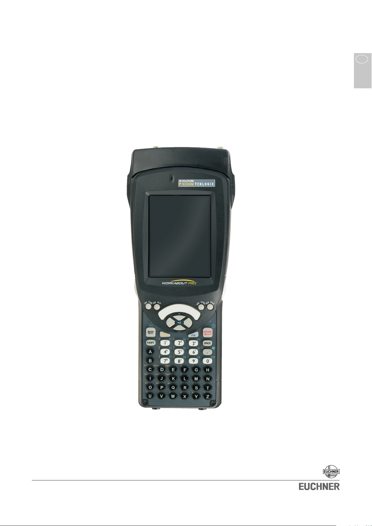
System Manual
Mobile Hand-Held Terminal
MHT-G2
GB
More than safety.
Page 2

System Manual Mobile Hand-Held Terminal MHT-G2
2 103702-01-07/08
Inhalt
Correct use 3
Exclusion of liability and warranty
General safety instructions
Structure
System components
Delivery of the individual system components 5
Setup
Insert the battery
Insert the SD-memory card
Installation of the Transponder Coding CE software
Attach the read head
The program surface of Transponder Coding CE (TCCE)
Structure of the menu
Configuration of Transponder Coding
Choose the language
Read/write settings
Reading and writing data carriers 1
Reading the data carriers 1
Editing data 1
Writing the data carriers 1
3
3
3
4
6
6
6
6
6
7
8
9
9
9
0
0
0
0
Control and maintenance 1
Service 1
1
1
Page 3
System Manual Mobile Hand-Held Terminal MHT-G2
Correct use
The mobile hand-held terminal MHT-G2 enables the user to read and write data
carriers of the EUCHNER system families CIS and EKS from any location. It is
based on the hand-held-computer PSION WORKABOUT PRO generation 2. Please
observe the notes for its correct use in the operating instructions given by the
manufacturer.
Exclusion of liability and warranty
If the a. m. conditions for intended use are not kept or the safety instructions not
observed, or else, possible maintenance work is not carried out as required, this
will lead to the exclusion of liability and the loss of warranty.
General safety instructions
Please follow the safety instructions given by the manual of the system manufacturer.
Important!
Before using, read the operating instructions and the system manual carefully
and keep these! Make sure that the operating instructions and the system manual
are always at hand for operation, setup and maintenance. Should this system
manual get lost, the document can be downloaded under www.EUCHNER.de.
Structure
The mobile hand-held terminal with pluggable read/write head completes the
EUCHNER Ident Systems CIS. The device is equipped with a compact, removable
read/write head.
For achieving an even better handling, the read/write head can be connected to
the hand-held terminal via a spiral cable. The cable is optionally available (order
no. 071759).
The robust splash-water-proof structure (IP54) guarantees perfect functioning even
under difficult conditions in rough industrial environments.
103702-01-07/08 3
Page 4
System Manual Mobile Hand-Held Terminal MHT-G2
4 103702-01-07/08
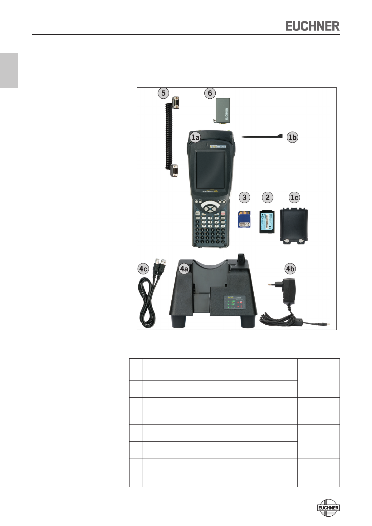
System components
The following illustration shows all available system components of the MHT-G2.
Overview table
Pos. Description Order No./
Mobile hand-held terminal, basic unit
1a
Touch-Pen
1b
Cover for battery box
1c
Battery
2
SD-memory card with software Transponder Coding CE (TCCE)
3
Docking station for recharge and for the PC communication via USB
4a
Adapter for docking station
4b
USB-cable for connecting the docking station to a PC
4c
Extension cable for read/write head
5
Depending on the configuration:
Read/write head CIT3-H2 for Ident System CIS3
Read/write head CIT3A-H2 for Ident System CIS3A
6
Read/write head CIT3A-MINI-H2 for Ident System CIS3A-Mini
Read/write head CIT3-IBS-H2 for Ident System CIS3-IBS
Item
099 975
MHT-G2-BU
099 981
MHT-G2-BA
099 982
MHT-G2-SD-TCCE
099 976
MHT-G2-DS
071 759
071 755
071 778
077 970
071 775
Page 5

System Manual Mobile Hand-Held Terminal MHT-G2
Check whether all parts are complete. The individual system components have to
be ordered separately.
In order to obtain a functional basic system, at least the following components
are required:
Mobile hand-held terminal basic unit (Pos. 1)
Battery (Pos. 2)
Read/write head (Pos. 6)
Docking station (Pos. 4)
SD-storage card with software (Pos. 3)
Delivery of the individual system components
Mobile hand-held basic device MHT-G2-BU (Order No. 099 975)
Mobile hand-held terminal basic unit (Pos. 1a) with operation system
Windows® Embedded CE 5.0
Touch-pen (Pos. 1b)
Cover for battery (Pos. 1c)
Quick Start Guide (Please keep this!)
CD (Order No. 103 730) with this system manual (Doc. No. 103 702) and the
manual by the system manufacturer (Doc. No. 103 803) Please keep these!
Licence and warranty directives
Battery MHT-G2-BA (Order No. 099 981)
Lithium-ion battery, 3000mAh, 3,7 V (Pos. 2)
SD-memory card with software Transponder Coding CE
MHT-G2-SD-TCCE (Order No. 099 982)
SD-memory card (Pos. 3)
Docking station MHT-G2-DS (Order No. 099 976)
Docking station (Pos. 4a)
Power supply with plug adapters of the following countries: EU, GB, USA, AUS
(Pos. 4b)
USB-cable (Pos. 4c)
Quick start guide
Warranty directives
Extension cable for read/write head (Order No. 071 759)
Extension cable (Pos. 5)
Read/write heads (Order No. see overview table)
Read/write head for your type of data carrier (Pos. 6)
Warning!
Use only original parts made by EUCHNER or the device manufacturer. If parts
not released by EUCHNER are used, functional disruptions or damages at the
device may result!
103702-01-07/08 5
Page 6

System Manual Mobile Hand-Held Terminal MHT-G2
6 103702-01-07/08
1
2
Setup
Insert the battery
Recharge the battery completely before power-on. Please see the operating instructions of the system manufacturer as to how to charge the battery.
Insert the SD-memory card
The Transponder Coding CE (TCCE) software for reading and writing of EUCHNER
Data carriers is delivered on a SD-memory card. As to how to insert the SD-memory
card, please see the operating instructions of the system manufacturer.
Installation of the Transponder Coding CE software
For installing the TCCE software, the memory card has to be inserted in the handheld terminal. By starting a special boot mode (Total Recall), the software is installed
from the SD-memory card on to the hand-held terminal.
Ensure that the write protection of the SD-memory card is not activated.
Proceed as follows:
Press the keys FN (blue) + FN (orange) + Enter/ON (red) simultaneously for
1.
six seconds.
The boot process starts.
Wait until the operating system has run up.
2.
Now, the icon for the software TCCE is shown on the desk top. The installation
is finished.
Attach the read head
Page 7

System Manual Mobile Hand-Held Terminal MHT-G2
The program surface of Transponder Coding CE (TCCE)
Double click on the symbol TCCE.
The following window appears:
Legend:
The buttons to start/abort the read/write process.
Optional button for the selection of the notation mode.
ASCII: the data content of each byte is displayed as ASCII character.
hex: the data content of each byte is displayed in hexadecimal notation
Editing area: Here, each byte is displayed in a separate field. The byte
chosen can be directly edited by clicking in the corresponding field with
the touch-pen. The byte no. constitutes a consecutive numbering of all
bytes in the data carrier, starting with byte no. 0.
Detailed view of the selected byte. Here, the content is displayed in decimal
and binary notation in addition.
103702-01-07/08 7
Page 8

System Manual Mobile Hand-Held Terminal MHT-G2
8 103702-01-07/08
Structure of the menu
Menu File
Command Open
Serves for opening the previously-stored data carrier contents.
Command Save and Save as ...
Is for storing data carrier contents. The read data are stored in the form of a special
XML document. To realize this, a separate XML-tag for certain transponder data
as well as for each single byte is filled with the contents.
Command Close
Closes the application.
Menu Mode
Command ASCII and hex
Serves for changing-over between hexadecimal and ASCII notation.
Menu Block
Command New
Establishes a new storage block in the editing window. The required size of the
storage block is asked for in advance.
Command Read
Starts the read process of the data carrier.
Command Write
Writes the data shown in the editing window on the data carrier.
Command Filling character
Fills the displayed data block with a freely selectable value. The data block that has
to be written can be defined by giving a start byte and the number of bytes.
Menu Options
Submenu Language
Here, you can change the program language.
Command Configuration
Here, you can change the read/write settings and e. g. the transponder type that
shall be read-out/written on.
Command Check ports ...
Serves for functional testing of the read/write head and for support purposes.
Help menu ?
Command About
Here, information on the software version of your TCCE software is provided.
Page 9

System Manual Mobile Hand-Held Terminal MHT-G2
Configuration of Transponder Coding
Choose the language
For choosing another language, proceed as follows:
In the menu Options, select the command Language.
1.
Choose the language.
2.
Read/write settings
In the menu Options, select the command Configuration.
1.
The window Configuration opens.
Legend:
COM Port: Select the setting for your read/write head. Usually, this is COM 8
Transponder: Select the Transponder type that shall be read.
CIS3/CIS3A: 16 Bytes
CIS3A-Mini: 116 Bytes or 5 Bytes (read-only data carrier)
CIS3-IBS: 16 kBytes or 32kBytes
EKS Electronic-Key: 116 Bytes
Beep Tone: Set, whether a signal shall resound at the end of the read /write
process.
Make the necessary settings and confirm with OK.
2.
103702-01-07/08 9
Page 10

System Manual Mobile Hand-Held Terminal MHT-G2
10 103702-01-07/08
Reading and writing data carriers
Reading the data carriers
Open the TCCE software.
1.
Click on Read.
2.
The window Read data from transponder appears.
If required, define the start byte from which shall be read and the number of
3.
bytes to be read. If you do not change anything at this stage, the complete
memory area of the data carrier is read.
Hold the read/write head with the active face directly at the data carrier. On
4.
CIS3, please observe orientation.
Click on OK.
5.
The read data appear in the editing area. In each field, the content of a byte
is displayed.
Attention!
Editing data
In the editing area, click on the byte that should be edited.
1.
The cursor blinks in the selected field. Via the keys, the content is overwritten
at your mobile hand-held terminal.
Repeat step 1 for each field until all requested data are entered.
2.
Writing the data carriers
With overwriting, the data carrier is overwritten. The data already present might
get lost during this process.
Click on Write.
1.
The window Write data to transponder appears.
If required, define the start byte from which shall be written and the number
2.
of bytes to be written. If you do not change anything at this stage, the
complete memory area of the data carrier is written.
Hold the read/write head with the active face directly at the data carrier.
3.
On CIS3, please observe orientation.
Click on OK.
4.
The data from the editing area are written on the data carrier.
Page 11

System Manual Mobile Hand-Held Terminal MHT-G2
Control and maintenance
Maintenance work is not required. Repairs at the device must only be carried out
by the manufacturer!
Service
Important!
When contacting our service department, please make sure to have the following
pieces of information at hand:
- Customer number or job account number
- This manual
- The device and accessories, if needed
- The software version on your device (Menu ?, select command Over.)
Service provided by:
EUCHNER GmbH + Co. KG
Kohlhammerstraße 16
D-70771 Leinfelden-Echterdingen
Service hotline:
+49 (0)7 11 / 75 97 - 301
E-Mail:
info@euchner.de
Internet:
www.euchner.de
103702-01-07/08 11
Page 12

More than safety.
Euchner GmbH + Co. KG
Kohlhammerstraße 16
D-70771 Leinfelden-Echterdingen
info@euchner.de
www.euchner.de
Issue:
103702-01-07/08
Title: System Manual Mobile Hand-Held Terminal MHT-G2
Copyright:
© EUCHNER GmbH + Co. KG, 07/2008
Subject to technical modifications,
all data supplied without liability.
Microsoft Windows® is a registered
trademark of Microsoft Corporation
 Loading...