

Page 1

Operating Instructions
Safety System
MGB-L..B-PNA-... (PROFINET)
with Data Structure Type A
Valid for MGB systems with the following order numbers:
105283
105284
105287
109856
109857
110816
113230
113231
113232
113233
114775
114776
115621
115622
121841
121843
121845
121847
More than safety.
Page 2

Operating Instructions Safety System MGB-L..B-PNA-... (PROFINET)
Contents
Correct use 3
Exclusion of liability and warranty 4
General safety instructions 5
Function 6
Interlocking module MGB-L0.B-PNA 6
Locking module MGB-L1.B-PNA and MGB-L2.B-PNA 6
Control of the guard locking 7
System overview 11
Evaluation module MGB-L.- 12
Handle module MGB-H-... 12
Escape release MGB-E-... (optional) 12
Dimension drawing 12
Mechanical release (only systems with guard locking) 13
Lockout mechanism 14
Escape release (optional) 14
Mounting 16
Mounting color cover 16
Changing the actuating direction (here: from right to left) 18
Controls and indicators 20
Protection against environmental effects 21
Electrical connection 21
Connections on bus module 22
Setup 23
Integrating into PROFINET and PROFIsafe 23
Replacement of an MGB system without programming device 24
System reset to factory settings 24
Teach-in operation (only for MGB unicode) 25
Mechanical function test 26
Electrical function test MGB-L0... 26
Electrical function test MGB-L1.../-L2... 26
PROFINET data bytes
PROFIsafe data bytes (safe input/output area) 28
Diagnostic messages of the MGB system 29
(unsafe input/output area) 27
System status table 31
Technical data 32
Troubleshooting 33
Latching fault when actuating the escape release 33
Fault reset 33
Inspection and service 34
Declaration of conformity 35
2
Page 3

Operating Instructions Safety System MGB-L..B-PNA-... (PROFINET)
Correct use
The system comprises at least one interlocking module MGB-L0.B or locking module
MGB-L1.B-... / MGB-L2.B-... and one handle module MGB-H...
The interlocking or locking module MGB-L..B-PN.-... is operated as an IO device
in the PROFINET (PROFIsafe).
Systems with interlocking module (MGB-L0.-...) are interlocking devices according
to EN 1088.
In combination with a separating safety guard and the machine control, the version
with interlocking prevents dangerous machine movements from occurring while
the safety guard is open.
For the control system, this means that
Ì starting commands which cause hazardous situations must become active only
when the safety guard is in the protective position.
The dangerous machine movement is stopped as soon as the safety guard is
opened.
Systems with locking module (MGB-L1.-.../MGB-L2.-...) are electromagnetic interlocking devices with guard locking and guard lock monitoring according to EN 1099.
In combination with a separating safety guard and the machine control, the MGB
system prevents the safety guard from being opened while a dangerous machine
movement is being performed.
For the control system, this means that
Ì starting commands which cause hazardous situations must become active
only when the safety guard is in protective position and the guard locking is in
locked position.
The locked position of the guard locking must be released only when the hazardous situation is no longer present.
Before safety components are used, a risk assessment must be performed on the
machine, e.g. in accordance with
Ì EN ISO 13849-1, Safety of machinery. Safety related parts of control systems.
General principles for design
Ì EN ISO 14121, Safety of machinery. Risk assessment. Principles.
Correct use includes compliance with the relevant requirements for installation
and operation, in particular
Ì EN ISO 13849-1, Safety of machinery. Safety related parts of control systems.
General principles for design
Ì EN 1088, Safety of machinery. Interlocking devices associated with guards.
Principles for design and selection
Ì EN 60204-1, Safety of machinery. Electrical equipment of machines. General
requirements.
The safety system MGB can only be combined with the intended modules in the
MGB system family.
On the modification of system components, EUCHNER provides no warranty for
safe function.
The customer is responsible for the safe overall function, especially for the safe
integration into the PROFIsafe environment.
3
Page 4

Operating Instructions Safety System MGB-L..B-PNA-... (PROFINET)
Important!
Ì The user is responsible for the integration of the device into a safe overall
system. For this purpose, the overall system must be validated, e.g. in accordance with EN ISO 13849-2.
Ì Correct use requires observing the permissible operating parameters (see
Technical data).
Ì If a product data sheet is included with the product, the information on the
data sheet applies in case of discrepancies with the operating instructions.
Ì In the estimation of the PL for the overall system, a maximum value of
100 years can be assumed for the MTTFd according to the limit value in
EN ISO 13849-1:2008, section 4.5.2. This corresponds to a minimum value
for the PFHd of 2.47x10⁻⁸/h.
Exclusion of liability and warranty
In case of failure to comply with the conditions for correct use stated above, or
if the safety instructions are not followed, or if any servicing is not performed as
required, liability will be excluded and the warranty void.
4
Page 5
Operating Instructions Safety System MGB-L..B-PNA-... (PROFINET)
General safety instructions
Safety switches fulfill personal protection functions. Incorrect installation or tampering can lead to fatal injuries to personnel.
Check the safe function of the safety guard particularly
Ì after any setup work
Ì after the replacement of an MGB component
Ì after an extended period without use
Ì after every fault
Independent of these checks, the safe function of the safety guard should be
checked at suitable intervals as part of the maintenance schedule.
Warning!
Loss of safety function in the event of incorrect connection or incorrect use.
Ì Safety switches must not be bypassed (bridging of contacts), turned away,
removed or otherwise rendered ineffective.
On this topic pay attention in particular to the measures for reducing the possibility of bypassing from EN 1088:1995+A2:2008, section 5.7.
Ì The switching operation is only allowed to be triggered by the intended han-
dle module MGB-H... that is positively fastened to the safety guard.
The device is only allowed to be installed and placed in operation by authorized
personnel
Ì who are familiar with the correct handling of safety components
Ì who are familiar with the applicable EMC regulations
Ì who are familiar with the applicable regulations on health and safety and ac-
cident prevention
Ì who have read and understood the operating instructions.
Important!
Prior to use, read the operating instructions and keep these in a safe place.
Ensure the operating instructions are always available during mounting, setup
and servicing. EUCHNER cannot provide any warranty in relation to the readability
of the CD for the storage period required. For this reason you should archive
a printed copy of the operating instructions. You can download the operating
instructions from www.EUCHNER.de.
5
Page 6

Operating Instructions Safety System MGB-L..B-PNA-... (PROFINET)
Function
Interlocking module MGB-L0.B-PNA
Together with a handle module, the interlocking module makes it possible to interlock movable safety guards. The combination also serves as a mechanical door
stop at the same time.
The following switch-on condition applies to safety bit SI9 (see also System status
table and section PROFIsafe data bytes):
Ì Safety guard closed (T)
Ì Bolt tongue inserted into interlocking module (R)
The interlocking module detects the position of the safety guard and the position
of the bolt tongue.
The bolt tongue in the handle module is moved into and out of the interlocking
module by actuating the door handle.
Locking module MGB-L1.B-PNA and MGB-L2.B-PNA
Important!
Together with a handle module, the locking module makes it possible to lock
movable safety guards. The combination also serves as a mechanical door stop
at the same time.
To operate the device as a guard lock according to EN 1088, the signals for door
position (T), bolt position (R) and guard lock monitoring (Z) must be polled in a
logical AND operator. This operator is already implemented in the safety bit SI10.
As an alternative, you can also link the bits SI3 to SI5 individually in your control
system.
The following switch-on condition applies to safety bit SI10 (see also System status
table and section PROFIsafe data bytes):
Ì Safety guard closed (T)
Ì Bolt tongue inserted into locking module (R)
Ì Locking arm in locking position (guard lock monitoring) (Z)
The locking module detects the position of the safety guard and the position of
the bolt tongue. The position of the locking arm is also monitored.
The bolt tongue in the handle module is moved into and out of the locking module
by actuating the door handle.
When the bolt tongue is fully inserted in the locking module, the locking arm locks
the bolt tongue in this position. Depending on the version, this locking is by spring
force or solenoid force.
6
Page 7
Operating Instructions Safety System MGB-L..B-PNA-... (PROFINET)
Version MGB-L1B-..., guard locking by spring force
The locking arm is kept in locked position by spring force and is unlocked by
solenoid force (closed-circuit current principle).
Version MGB-L2B-..., guard locking by solenoid force
The locking arm is kept in locked position by solenoid force and unlocked by spring
force when the solenoid is switched off (open-circuit current principle).
Warning!
Ì The safety guard can be opened immediately in the event of interruption of
the solenoid power supply!
Ì Usage only in special cases after strict evaluation of the accident risk (see
EN 1088:1995+A2:2008, section 5.5)!
Typical case: If the risk of accidental locking inside a safety guard during a power
failure is higher than the risk of ineffective guard locking.
Control of the guard locking
Important!
Important!
From MGB version V2.36.4, the factory ensures that control is possible only from
the safe control area. Here, it was determined in the firmware that only bit S01
is evaluated.
By changing the parameters in the configuration tool of your control system, it can
be set that bit 016 is evaluated as well.
Control of the guard locking via the safe control area does not provide increased
safety, as the device-internal control of the guard locking is only of single-channel
design.
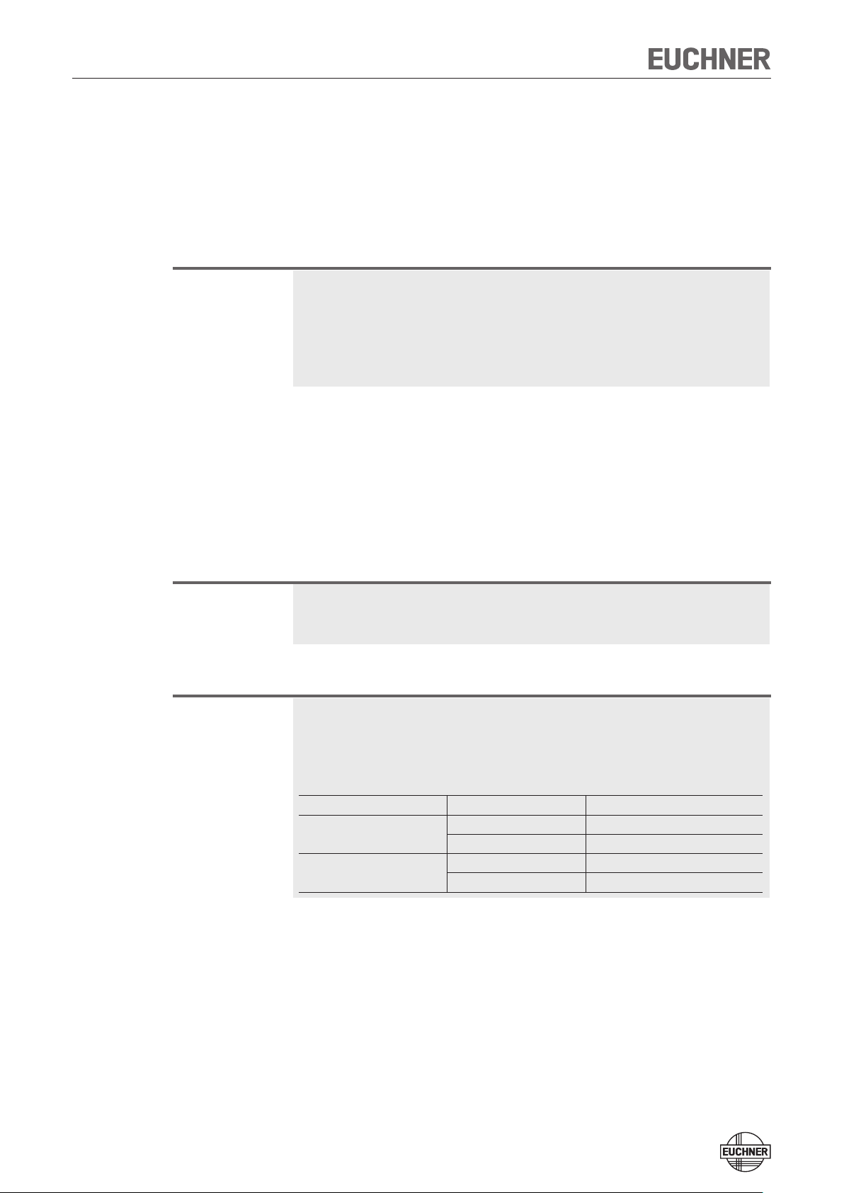
The following functions depend on the MGB version, the version of the GSD file
and the settings made there.
Compare the specified versions with those on your device and your GSD file. The
version number of your MGB can be found on the type plate (format: V X.XX.X).
MGB version GSD version Continue in section ...
up to and including V 2.35.4
from V 2.36.4
..._110026-20110725
..._110026-20110815
..._110026-20110725
..._110026-20110815
Case A
Case A
Case B
Case C
7
Page 8
Operating Instructions Safety System MGB-L..B-PNA-... (PROFINET)
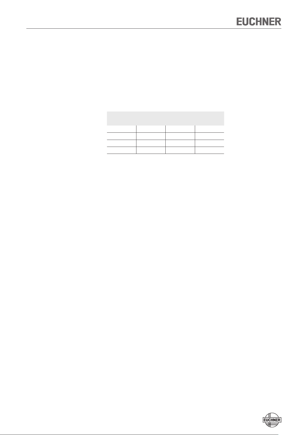
Case A
You have an MGB with a version number of V 2.35.4 and a GSD file with a version
number of ..._110026-20110725 or older. Or you have an MGB with a version number of V 2.35.4 and a GSD file with a version number from ..._110026-20110815.
The guard locking solenoid is controlled if
Ì bit O16 OR bit SO1 = 1
Truth table:
PROFINET bit PROFIsafe bit Guard locking with
O16 SO1 MGB-L1... MGB-L2...
0 0 active inactive
0 1 inactive active
1 0 inactive active
1 1 inactive active
What must be observed?
The guard locking can be controlled from the unsafe control area. The combination
with the more up-to-date GSD file allows a parameter to specify which bits are to
be used for control. However, the device does not support this function. In other
words, the setting in your configuration software remains ineffective.
8
Page 9
Operating Instructions Safety System MGB-L..B-PNA-... (PROFINET)
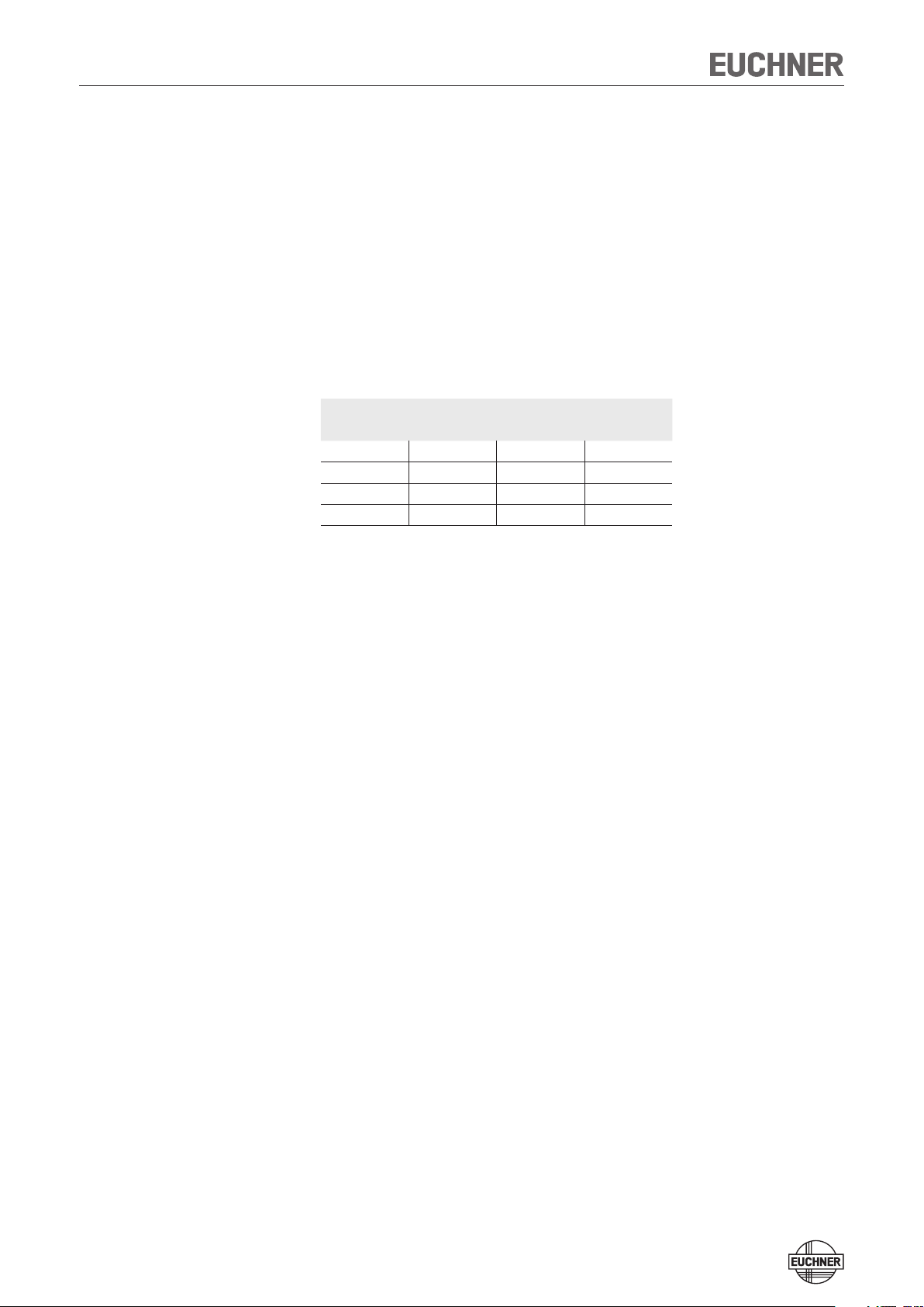
Case B
You have an MGB with a version number of V 2.36.4 and a GSD file with a version
number of ..._110026-20110725 or older.
The guard locking solenoid is controlled if
for MGB-L1...
Ì bit SO1 = 1
for MGB-L2...
Ì bit O16 OR bit SO1 = 1
Truth table:
PROFINET bit PROFIsafe bit Guard locking with
O16 SO1 MGB-L1... MGB-L2...
0 0 active inactive
0 1 inactive active
1 0 active active
1 1 inactive active
What must be observed?
Bit O16 does not have any function with version MGB-L1... In existing installations
in which old devices are replaced with new ones (e.g. due to defect), malfunctions
can occur if control via bit O16 was programmed in the PLC.
Remedy:
1. Replace the old GSD file with a version from ..._110026-20110815.
2. In the parameter Locking module – solenoid control, activate unsafe control
of the guard locking solenoid via bit O16.
3. Set bit SO1 permanently to the value 1.
¨ The guard locking solenoid is controlled exclusively via bit O16
or
Ì Change the control bit from O16 to SO1 in your PLC program
9
Page 10
Operating Instructions Safety System MGB-L..B-PNA-... (PROFINET)
Case C
You have an MGB with a version number of V 2.36.4 and a GSD file with a version
number from ..._110026-20110815.
The guard locking solenoid is controlled if:
Ì bit SO1 = 1 (factory setting)
Truth table:
PROFINET bit PROFIsafe bit Guard locking with
O16
Not relevant
0 0 active inactive
0 1 inactive active
1 0 active inactive
1 1 inactive active
What must be observed?
You can define in the GSD file whether bit O16 may be used for control in addition
to bit SO1. The setting is specified in the parameter Locking module – solenoid
control.
SO1 MGB-L1... MGB-L2...
If O16 is additionally used, the guard locking solenoid is controlled if
for MGB-L1...
Ì bit SO1 AND bit 016 = 1
for MGB-L2...
Ì bit SO1 OR bit 016 = 1
Truth table:
PROFINET bit PROFIsafe bit Guard locking with
O16 SO1 MGB-L1... MGB-L2...
0 0 active inactive
0 1 active active
1 0 active active
1 1 inactive active
10
Page 11
Operating Instructions Safety System MGB-L..B-PNA-... (PROFINET)
System overview
Mounting plate
Escape release (optional)
(MGB-E...)
Evaluation module
(MGB-L...)
Handle module
(MGB-H...)
Bus module
(Profinet)
(MGB-B...)
Figure 1: Components at a glance (sample configuration)
Note: MGB-PN systems are completely factory configured. The configuration must not be changed subsequently. The illustrations in this section can
deviate from your system and serve only as examples. The configuration
of your MGB system can be found in the data sheet included with every
MGB system.
Key:
1
LED indicator
2
Power supply
3
PROFINET connection
Note:
Depending on the version, additional
controls and indicators may be integrated
into the cover and a mounting plate can
be included. The type of connection can
vary depending on the version. See enclosed data sheet.
Bus module MGB-B-...-PN
1
2
3
Figure 2: Bus module MGB-B-...-PN (configuration example)
11
Page 12

Operating Instructions Safety System MGB-L..B-PNA-... (PROFINET)
1 2 3 4 5
Evaluation module MGB-L.-
Key:
1
LED indicator
2
Cover for mechanical release
3
Locking arm (only version with
guard locking)
4
Auxiliary marking for max. permit-
ted mounting distance
Note:
Depending on the version, a mounting
plate can be included. See enclosed
data sheet.
Key:
1
Door handle
2
Locking pins for housing cover
and handle adjustment
3
Lockout mechanism
4
Bolt tongue
Note:
Depending on the version, a mounting
plate can be included. See enclosed
data sheet.
1
2
3
4
Figure 3: Evaluation module MGB-L.-
Handle module MGB-H-...
1
2
3
4
Figure 4: Handle module MGB-H-...
Key:
1
Door handle
2
Setscrew
3
Cover
4
Actuation axis, length 118 mm (in-
cluded)
Alternatively:
length 250 mm (order No. 110 976)
5
Protective sleeve
Note:
Depending on the version, a mounting
plate can be included. See enclosed data
sheet.
Escape release MGB-E-... (optional)
Figure 5: Escape release MGB-E-...
Dimension drawing
See enclosed data sheet
12
Page 13

Operating Instructions Safety System MGB-L..B-PNA-... (PROFINET)
Mechanical release (only systems with guard locking)
In the event of service, the guard locking can be released with the mechanical
release irrespective of the state of the solenoid (see Figure 6).
The locking screw must be screwed back in and sealed after use (for example with
sealing lacquer). Tightening torque 0.5 Nm.
1. Undo locking screw.
2. Lift locking arm using a screwdriver and actuate door handle.
Important!
The system enters into a latching fault when the mechanical release is actuated.
See System status table on page 31, status Signal sequence erroneous (DIA1
flashes 7 times).
Note:
The system might not enter into a latching fault if the mechanical release is actuated very slowly.
Figure 6: Mechanical release
13
Page 14

Operating Instructions Safety System MGB-L..B-PNA-... (PROFINET)
Lockout mechanism
If the lockout mechanism is pivoted out, the bolt tongue cannot be extended. The
lockout mechanism can be secured with padlocks (see Figure 7).
To pivot out, press the grooved part (only possible with bolt tongue retracted).
Key:
1
Padlock ∅ min. 2 mm, ∅ max.
10 mm
Note:
You can fit a maximum of 3 locks
Ø 8 mm..
2
Automatically extending, second
lockout mechanism
Padlock ∅ min. 6 mm, ∅ max.
10 mm
1
Order no.. 100464 (right)
Order no.. 106619 (left)
Figure 7: Lockout mechanism secured with padlock
Order no.. 111157 (right)
Order no.. 111158 (left)
2
Escape release (optional)
The escape release is used to open a locked safety guard from the inside without
tools.
Important!
Ì The escape release is not a safety function.
Ì The machine manufacturer must select and use a suitable release (escape
release,
Ì emergency unlocking, etc.) for a specific application. A risk assessment ap-
praisal is required for this
Ì purpose. It may be necessary to take specifications from a product standard
Ì into account.
Ì The correct function must be checked at regular intervals.
Ì Loss of the release function due to tension on the actuator. The door must
not
Ì be under tension during release.
Ì Please observe the notes on any enclosed data sheets.
Ì The actuation axis for the escape release must be inserted min. 10 mm into
the handle module.
Ì For profile widths larger than 40 mm and when using mounting plates, use a
250-mm actuation axis (order No. 106 761) and cut it to size.
Ì In case of profile widths smaller than 40 mm, cut actuation axis and protective
sleeve to length.
Ì Align escape release at right angles to the handle module (see figure on left
and Figure 8).
Ì Fit escape release such that operation, inspection and maintenance are pos-
sible.
14
Page 15

Operating Instructions Safety System MGB-L..B-PNA-... (PROFINET)
A
Important!
The following applies to systems with guard locking: The system enters into a
latching fault when the escape release is actuated. See System status table on
page 31, status Signal sequence erroneous (DIA1 flashes 7 times).
The system might not enter into a latching fault if the escape release is actuated
very slowly.
Preparation of the escape release
Example with mounting plates:
(10)
Actuation axis
Protective sleeve
4
Mounting
plates
3
4
3,5
2
1
1
Fit door handle
2
Insert actuation axis. The locking ring A must be in contact with
the escape release B
3
Tighten setscrew to 2 Nm
4
Fit protective sleeve
Figure 8: Preparing escape release
D
250
58,5
D + 13,5
55,5
182
(+ 4 mm per plate)
D + 3
(+ 4 mm per plate)
4
B
15
Page 16

Operating Instructions Safety System MGB-L..B-PNA-... (PROFINET)
1 2
Mounting
Warning!
Mounting must be performed only by authorized personnel.
With two-wing hinged doors, one of the two door wings additionally must be latched
mechanically.
Use a rod latch (Item) or a double-door lock (Bosch Rexroth) for this purpose, for
example.
Tip!
The color and labeling of pushbuttons and indicators can be modified.
At least two M6 screws each must be used to install the evaluation module and
the handle module (tightening torque 4 Nm).
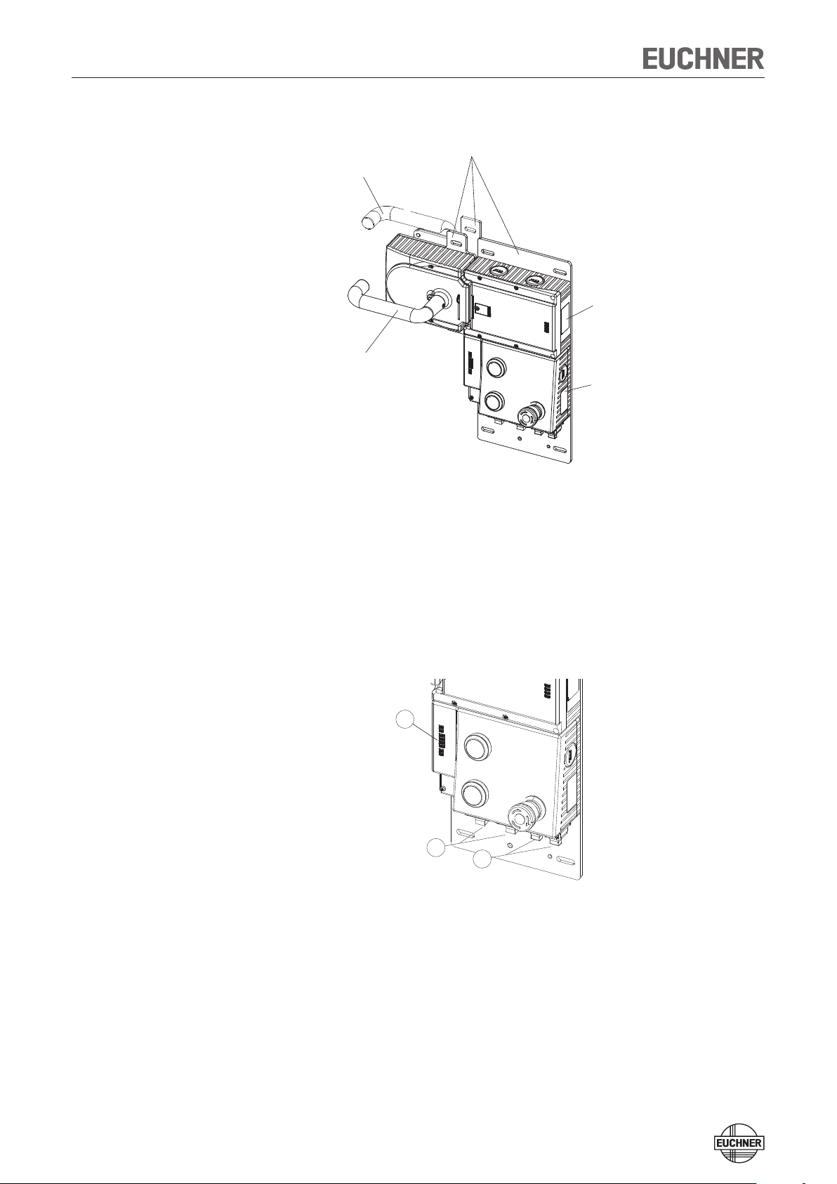
For installation steps see Figure 9.
Install system so that
Ì Operation of the mechanical release as well as inspection and maintenance are
possible.
Mounting
1
Removing
Ì The locking screw of the escape release must be returned to its original posi-
tion and sealed before putting into operation (for example with sealing lacquer).
Mounting color cover
Click!
2
3
Color cover
90°
16
Page 17

Operating Instructions Safety System MGB-L..B-PNA-... (PROFINET)
Figure 9: Installation example for door hinged on the right (general view)
17
Page 18

Operating Instructions Safety System MGB-L..B-PNA-... (PROFINET)
Changing the actuating direction (here: from right to left)
Important!
It is only possible to make this change when the bolt tongue is not extended and
an escape release is not yet mounted.
As supplied, the handle module is set either for doors hinged on the right or for
doors hinged on the left.
Based on the example of a handle module for doors hinged on the right this means:
Ì The safety guard opens by pressing down the door handle.
Ì The system is mounted the other way up for doors hinged on the left. In other
words, the safety guard opens by pressing up the door handle (see Figure 10).
For this reason the actuating direction of the door handle must be changed
(see Figures 10 - 15).
(This is similar for handle modules for doors hinged on the left.)
1
OPEN
CLOSED
1
Press door handle up.
Figure 10: Changing actuating direction, step
4
5
1
3
2
2
Unscrew locking pins.
3
Push cover aside.
Figure 11: Changing actuating direction, steps 2 and
4 mm
6
b
a
7
3
4
Lift the locking pin on the door handle using a screwdriver
and hold it in this position.
5
Turn door handle to the right.
Figure 12: Changing actuating direction, steps 4 and
8
6
Only if using an escape release: using the hexagon head
screw, turn the joint counterclockwise from position (a) to
position (b).
7
Close cover.
8
Screw in locking pins and tighten to 2 Nm.
5
Figure 13: Changing actuating direction, steps 6 to
18
8
Page 19

Operating Instructions Safety System MGB-L..B-PNA-... (PROFINET)
3 mm
9
10
CLOSED
OPEN
9
Loosen the setscrew.
AT
Reposition the door handle by 90° in clockwise direction and
fasten it again. Tighten setscrew to 2 Nm.
Figure 14: Changing actuating direction, steps 9 and
AK
State after repositioning.
AT
Figure 15: Changing actuating direction, final state
19
Page 20

Operating Instructions Safety System MGB-L..B-PNA-... (PROFINET)
Controls and indicators
LEDs on the bus module
LED Color Description
Link 1 and
Link 2
Data 1 and
Data 2
SF red System error:
BF red Bus error:
ON green Self test OK:
UB green Power supply OK:
green Bus plug inserted:
statically on
yellow Data transfer:
flashing
statically on
(see section on diagnostic messages of
the MGB system)
statically on
(see section on diagnostic messages of
the MGB system)
statically on
Subscriber passivated: flashing
statically on
Binary coding of the
DIPswitches for PROFIsafe address (factory
setting: 135)
124816
32
51 2 3 4
361 2
4
64
128
256
512
default address:
128 + 4 + 2 + 1 = 135
LEDs on evaluation module
see System status table
State
DIA2
Power
DIA1
ON
OFF
OFF
ON
Link1
Data1
Link2
Data2
SF
BF
ON
UB
1
Link
1
Data
Link
2
Data
2
SF
BF
ON
U
B
DC24V DC24V
X1 X3 X4
X2
Figure 16: Display elements and switches / binary coding of the DIPswitches
for PROFIsafe address (factory setting: 135)
Cover for DIPswitches
DIPswitches for PROFIsafe address
For coding see above
PN1PN2
6
51 2 3 4
12
3
4
20
Page 21

Operating Instructions Safety System MGB-L..B-PNA-... (PROFINET)
Protection against environmental effects
Lasting and correct safety function requires that the system must be protected
against foreign bodies such as swarf, sand, blasting shot, etc., which can become
lodged in the locking and handle modules. For this purpose a suitable installation
position should be selected.
Cover device during painting work!
Electrical connection
Warning!
Mounting must be performed only by authorized personnel.
Caution!
Risk of damage to equipment or malfunctions as a result of incorrect connection.
Ì All the electrical connections must either be isolated from the mains supply
by a safety transformer according EN IEC 61558-2-6 with limited output voltage in the event of a fault, or by other equivalent isolation measures.
Ì For use and operation as per the requirements, a power supply with the
feature "for use in class 2 circuits" must be used. The same requirement applies to the safety outputs.
Alternative solutions must comply with the following requirements:
a) Electrically isolated power supply unit with a max. open-circuit voltage of 30
V/DC and a limited current of max. 8 A.
b) Electrically isolated power supply unit in combination with fuse as per UL248.
This fuse should be designed for max. 3.3 A and should be integrated into
the 30 V/DC voltage section.
Attention:
Important!
Ì The supply for further subscribers on the bus may be forwarded via the Eu-
chner MGB system. The entire supply current through the MGB must not be
higher than specified in the section Technical data.
Ì The function earth must be connected. An M6 threaded bore is available
on the mounting plate for this purpose.
Ì If the device does not appear to function when operating voltage is applied
(e.g. UB LED does not illuminate), the safety switch must be returned unopened to the manufacturer.
Ì To ensure the stated degree of protection IP67 is achieved, the cover
screws must be tightened to a tightening torque of 1 Nm.
Ì Tighten screw for the cover for the mechanical release to 0.5 Nm.
21
Page 22

Operating Instructions Safety System MGB-L..B-PNA-... (PROFINET)
Connections on bus module
The bus module includes the PROFINET connections (X3 and X4) and the power
supply connections (X1 and X2). Depending on the version, connection is made via
push-pull plugs according to IEC 61076-3-117, variant 14 or 7/8"-plugs according
to ANSI/B93.55M-1981 and M12 plugs (d-coded) according to IEC 61076-2-101.
The bus module includes a PROFINET RT switch for Ethernet connection.
Terminal assignment for version with push-pull plugs
Pin Description
X1.1 L1 operating voltage DC 24 V
X1.2 N1 operating voltage 0 V
X1.3 L2 auxiliary power* DC 24 V
X1.4 N2 auxiliary power* 0 V
X1.5 Function earth
* The auxiliary power is not required for the MGB
system
X2: For looping through for connected
devices
X2.1 L1 operating voltage DC 24 V
X2.2 N1 operating voltage 0 V
X2.3 L2 auxiliary power* DC 24 V
X2.4 N2 auxiliary power* 0 V
X2.5 Function earth
Pin Description
X1.1 N2 auxiliary power *0 V
X1.2 N1 operating voltage 0 V
X1.3 Function earth
X1.4 L1 operating voltage DC 24 V
X1.5 L2 auxiliary power* DC 24 V
* The auxiliary power is not required for the MGB
system
X2: For looping through for connected
devices
X2.1 N2 auxiliary power *0 V
X2.2 N1 operating voltage 0 V
X2.3 Function earth
X2.4 L1 operating voltage DC 24 V
X2.5 L2 auxiliary power* DC 24 V
Pin Description
X3.1 Receive Data +RD
X3.2 Receive Data -RD_N
X3.3 Transmit Data +TD
X1 X2 X3 X4
1 2 3 4 5 1
1L+ 2L+
IN OUT IN OUT
2 3 4 5
1L+
8 1 8 1
2L+
RJ45
X3.4 Ground GND (RJ45)
X3.5 Ground GND (RJ45)
X3.6 Transmit Data -TD_N
X3.7 Ground GND (RJ45)
X3.8 Ground GND (RJ45)
X4: For looping through for connected
devices (integrated RT switch)
X4.1 Receive Data +RD
X4.2 Receive Data -RD_N
X4.3 Transmit Data +TD
X4.4 Ground GND (RJ45)
X4.5 Ground GND (RJ45)
X4.6 Transmit Data -TD_N
X4.7 Ground GND (RJ45)
X4.8 Ground GND (RJ45)
Terminal assignment for version with 7/8" and M12 plugs
Pin Description
X3.1 Transmit Data +TD
X3.2 Receive Data +RD
1
2
X1(OUT)
(Stift / male)
3
7/8"
5 5
4
4
X2 (IN)
(Buchse / female)
7/8"
X3 (PN2)
1
214
3
(Buchse)
(female)
d-kodierung
M12
X4 (PN1)
1 2
4
3
(Buchse)
(female)
d-kodierung
M12
X3.3 Transmit Data -TD_N
X3.4 Receive Data -RD_N
Function earth on plug housing
2
3
X4: For looping through for connected
devices (integrated RT switch)
X4.1 Transmit Data +TD
X4.2 Receive Data +RD
X4.3 Transmit Data -TD_N
X4.4 Receive Data -RD_N
Function earth on plug housing
22
Page 23

Operating Instructions Safety System MGB-L..B-PNA-... (PROFINET)
Setup
Integrating into PROFINET and PROFIsafe
Attention:
The parameters "Update time" and "F-WD-Time" have a decisive effect on the
reaction time of the safety function. The safety function could be lost if the reaction times are too long.
Important!
You will require the corresponding GSD file in GSDML format in order to integrate
the MGB system:
Ì GSDML-Vx.x-EUCHNER-MGB_110026-YYYYMMDD.xml
You can find the GSD file in the download area at www.EUCHNER.de. You can
also find the file GSD_Info_MGB_Profinet.pdf there. The file helps you to find the
right GSB file for your device.
Prior to commissioning, the GSD file must be imported into the configuration
software of the control system (see control system manual).
You must perform the following steps to integrate the MGB system into PROFINET:
1. Configure the MGB system with the configuration software of the control
system and assign parameters.
The following PROFINET parameters must be set:
Ì Device name (factory setting from GSD file): [euchnermgb].
Ì IPaddress: optionally fixed or dynamic
Ì Update time
Recommendation [32 ms]
Maximum value [128 ms]
(with number of repeat cycles = 3)
The following PROFIsafe parameters must be set:
Ì F_dest_adr (PROFIsafe address): this is generally assigned automatically by the
control system.
Ì F_WD_Time (time during which the control system expects a response by the
PROFIsafe device): [xxx ms]. Factory setting from GSD file: (600 ms)
2. Set the PROFIsafe address (F_dest_adr) on the MGB system using the DIPswitches (see Figure 10). Important: Identical addresses must be set in the
control system and on the device.
3. Save the configuration and transfer it to the control system.
23
Page 24

Operating Instructions Safety System MGB-L..B-PNA-... (PROFINET)
Replacement of an MGB system without programming device
If servicing is required, the MGB system is easy to replace with a new one. For this
purpose the following prerequisites must be met:
Ì The DIPswitch settings on the new device must match those on the old device.
Ì Your Profinet master must support the automatic replacement of Profinet sub-
scribers.
Ì Your Profinet topology must be correctly configured.
Ì There must be no device name in the MGB system.
This field is empty in the as-delivered state. Systems that already contain a
name must first be reset to the factory settings.
Once these conditions are met, simply replace the old system with the new system.
The Profinet bus does not need to be switched off for this purpose.
System reset to factory settings
You will find detailed instructions in the manual for the configuration software for
your control system.
24
Page 25

Operating Instructions Safety System MGB-L..B-PNA-... (PROFINET)
Teach-in operation (only for MGB unicode)
The handle module must be assigned to the locking module using a teach-in function before the system forms a functional unit.
During a teach-in operation the system is in the safe state (bit SI10 is not set).
Important!
Ì The locking module disables the code for the previous handle module if
teach-in is carried out for a new handle module. Teach-in is not possible
again immediately for this device if a new teach-in operation is carried out.
The disabled code is deleted in the locking module only after a third code
has been taught.
Ì The locking module can only be operated with the last handle module taught.
Ì If, in the teach-in standby state, the locking module detects the handle
module taught-in or a disabled handle module, the teach-in standby state is
ended immediately and the locking module changes to the normal state or
indicates an error.
Ì If the bolt tongue is in the operating distance for less than 60 s, the handle
module is not taught.
Teaching in handle module
1. Fit handle module.
2. Close safety guard. Check for correct alignment and distance using the
marking on the locking module and re-adjust if necessary.
3. Insert bolt tongue in the locking module.
4. Apply operating voltage to the locking module.
Ì Teach-in process starts, green LED (DIA1) flashes slowly (approx. 2 Hz). The
teach-in standby state is active for 3 minutes after switch on. During teach-in,
the locking module checks whether the handle module is a disabled handle
module. Provided this is not the case, the teach-in operation is completed after
approx. 60 seconds, and the green LED (DIA1) goes out. The new code has
now been stored, and the old code is disabled.
5. Reset via bit O18 to activate the handle module's code from the teach-in
operation in the locking module.
25
Page 26

Operating Instructions Safety System MGB-L..B-PNA-... (PROFINET)
Mechanical function test
It must be possible to easily insert the bolt tongue into the interlocking or locking
module. To check, close safety guard several times and actuate door handle.
If available, check function of the escape release. It must be possible to operate
the escape release from the inside without excessive effort.
Electrical function test MGB-L0...
1. Switch on operating voltage or reset using output bit O18.
2. Close all safety guards and insert the bolt tongue into the locking module.
Ì The machine must not start automatically.
3. Enable operation in the control system.
Ì The machine must switch off and it must not be possible to start it as long as
the safety guard is open.
Repeat steps 2-4 for each safety guard.
Electrical function test MGB-L1.../-L2...
1. Switch on operating voltage or reset using output bit O18.
2. Close all safety guards and insert the bolt tongue into the locking module.
In the case of guard locking by solenoid force, ¨ activate guard locking.
Ì The machine must not start automatically.
Ì It must not be possible to open the safety guard.
Ì The yellow STATE LED illuminates continuously.
3. Enable operation in the control system.
Ì It must not be possible to deactivate guard locking as long as operation is
enabled.
4. Disable operation in the control system and deactivate guard locking.
Ì The safety guard must remain locked until there is no longer any risk of injury.
Ì It must not be possible to start the machine as long as the guard locking is
deactivated.
Ì It must be possible to open the safety guard.
Repeat steps 2-4 for each safety guard.
26
Page 27

Operating Instructions Safety System MGB-L..B-PNA-... (PROFINET)
PROFINET data bytes (unsafe input/output area)
Note: See the supplied data sheet for details on the bit assignment
Profinet RT modules 3 bytes IO:
Assignment in the input area of the bus master:
1st byte I8 I7 I6 I5 I4 I3 I2 I1
2nd byte I16 I15 I14 I13 I12 I11 I10 I9
Depending on your configuration variant
(refer to the data sheet of your device for the exact bit allocation)
3rd byte I24 I23 I22 I21 I20 I19 I18 I17
I17: Device diagnosis (PROFIsafe error 72): message present. Diag-
nostic code: see table of device-specific messages.
I18: Device diagnosis, device-specific message 274(4) "Plausibility
check found an error (e.g. escape release actuated)"
I19: Device diagnosis, device-specific message 272(1) or 273(1) "Er-
ror in emergency stop"
I20: Device diagnosis, device-specific message 272(2) or 273(2) "Er-
ror in enabling switch"
I21: Device diagnosis, device-specific message 272(6) or 273(6) "Er-
ror in operating mode selector switch"
I22: n.c.
I23: n.c.
I24: Mechanical life > 1 million operating cycles
Assignment in output area of the bus master:
1st byte O8 O7 O6 O5 O4 O3 O2 O1
2nd byte O16 O15 O14 O13 O12 O11 O10 O9
Depending on your configuration variant
(refer to the data sheet of your device for the exact bit allocation)
3rd byte O24 O23 O22 O21 O20 O19 O18 O17
O17: Device diagnosis: acknowledge message; acknowledgment of
I19, I20 or I21. I17 is also acknowledged if only one message is
present.
O18: Trigger MGB locking module reset: acknowledge message; ac-
knowledgment of I18. I17 is also acknowledged if only one mes-
sage is present.
O19: n.c.
O20: n.c.
O21: n.c.
O22: n.c.
O23: n.c.
O24: n.c.
See section on diagnostic messages of the MGB system for details.
27
Page 28

Operating Instructions Safety System MGB-L..B-PNA-... (PROFINET)
PROFIsafe data bytes (safe input/output area)
Note: See the supplied data sheet for details on the bit assignment
Profisafe assignment in the output area of the bus master:
Byte n+0 SO8 SO7 SO6 SO5 SO4 SO3 SO2 SO1
Byte n+1 SO16 SO15 SO14 SO13 SO12 SO11 SO10 SO9
Byte n+2 Profisafe internal
Byte n+3 Profisafe internal
Byte n+4 Profisafe internal
Byte n+5 Profisafe internal
SO1: Control of guard locking solenoid (for function, see section on
control of guard locking, p. 6, only available for L1 and L2)
SO2: n.c
SO3: n.c
SO4: n.c
SO5: n.c
SO6: n.c
SO7: n.c
SO8: n.c
SO9: n.c
SO10: n.c
SO11: n.c
SO12: n.c
SO13: n.c
SO14: n.c
SO15: n.c
SO16: n.c
Profisafe assignment in the input area of the bus master:
Byte n+0 SI8 SI7 SI6 SI5 SI4 SI3 SI2 SI1
Byte n+1 SI16 SI15 SI14 SI13 SI12 SI11 SI10 SI9
Byte n+2 Profisafe internal
Byte n+3 Profisafe internal
Byte n+4 Profisafe internal
Byte n+5 Profisafe internal
SI1: Emergency stop
SI2: Enabling switch
SI3: Door position (T)
SI4: Bolt position (R)
SI5: Guard locking (Z)
SI6:
SI8:
SI9:
SI10:
SI11: n.c
SI12: n.c
SI13: n.c
SI14: n.c
SI15: n.c
SI16: Reserved for customer-specific function
Enabling contacts closed (three-stage enabling switch in center
position), no evaluation of the edges
Operating mode selector switch (used, 3 bits)SI7:
SK (T AND R)
Door position + bolt position (available for L0, L1 and L2)
ÜK (T AND R AND Z)
Door position + bolt position + guard locking (available only for
L1 and L2)
28
Page 29

Operating Instructions Safety System MGB-L..B-PNA-... (PROFINET)
Diagnostic messages of the MGB system
All diagnostic messages are listed below. The scope of possible messages may differ according to the version of the
MGB system.
PROFIsafe messages
Display via LED BF (see Figure 10)
No. Description Measures/remedying errors
64 Error when comparing the
Profisafe destination address
(F_Dest_Add)
65 Invalid Profisafe destination ad-
dress (F_Dest_Add)
66 Invalid Profisafe source address
(F_Sourrce_Add)
67 Value for the Profisafe time moni-
toring is 0 ms (F_WD_TIME)
68 Parameter F_SIL exceeds SIL of
the device-specific application
69 Parameter F_CRC_Length does
not match the generated values
70 Version for F_Parameter not
correct
71 Error CRC 1- (during booting) 1. Restart system
72 Device-specific diagnostic infor-
mation (see following table)
1. Check DIPswitch position
2. Restart system
1. Check addressing
2. Restart system
1. Check addressing
2. Restart system
1. Check system times
2. Restart system
1. Check settings
2. Restart system
1. Check settings
2. Restart system
1. Check configuration
2. Restart system
1. Identify error via input bit I17
2. For error remedy, see the
following table with devicespecific messages
Device-specific diagnostic information
Display via LED SF (see Figure 10)
Discrepancy error (two-channel monitoring detected an error)
Note:
Ì The discrepancy time is the maximum time during which channel 1 and
channel 2 may have different signal states.
Ì If acknowledgment was unsuccessful, send the device to the manu-
facturer.
No. Description Measures/remedying errors
272 Discrepancy time exceeded 1. Search for cause
272(1) Emergency-stop discrepancy
time exceeded
272(3) Door position discrepancy time
exceeded
272(4) Bolt-position discrepancy time
exceeded
272(5) Guard locking discrepancy time
exceeded (only version with
guard locking)
2. Acknowledge fault (via output
bit O17)
1. Press emergency stop
2. Acknowledge fault (via output
bit O17)
1. Open the door
2. Acknowledge fault (via output
bit O17)
1. Open the door
2. Acknowledge fault (via output
bit O17)
1. Open the door
2. Acknowledge fault (via output
bit O17)
Test-pulse error (short-circuit monitoring detected an error)
Note:
Ì Emergency Stop must not be pressed during acknowledgment.
Ì If acknowledgment was unsuccessful, send the device to the manu-
facturer.
No. Description Measures/remedying errors
273 Test pulse erroneous Safety function is switched off
273(1) Emergency-stop test pulses
erroneous
273(3) Door-position test pulses er-
roneous
273(4) Bolt-position test pulses er-
roneous
273(5) Guard-locking test pulses er-
roneous
while no test pulses are being
detected.
1. Check system
2. Acknowledgment via output
bit O17 necessary.
Safety function is switched off
while no test pulses are being
detected.
1. Pull Emergency Stop
2. Acknowledgment via output
bit O17 necessary.
Safety function is switched off
while no test pulses are being
detected.
1. Close door
2. Acknowledgment via output
bit O17 necessary.
Safety function is switched off
while no test pulses are being
detected.
1. Close door
2. Acknowledgment via output
bit O17 necessary.
Safety function is switched off
while no test pulses are being
detected.
1. Close and lock door
2. Acknowledgment via output
bit O17 necessary.
General messages of the overall system
No. Description Measures/remedying errors
274(1) Max. (mech.) life exceeded Message via input bit I24
274(2) Internal device error Please contact our support
274(3) Signal sequence erroneous (e.g.
broken bolt tongue recognized)
274(4) Plausibility test detected an
error (e.g. escape release
actuated)
274(5) Locking module in error Please contact our support
Message cannot be reset
organization!
1. Check mech. functions
2. Acknowledge fault (via output
bit O18). The safety door
must be open.
Important: The resetting procedure is contained in the section
"Latching fault when actuating
the escape release"
Ì Acknowledge fault (via output
bit O18)
organization!
29
Page 30

Operating Instructions Safety System MGB-L..B-PNA-... (PROFINET)
PROFIsafe errors
No. Description Measures/remedying errors
276(1) Starting error PROFIsafe Please contact our support
276(2) Memory error RAM Please contact our support
276(3) Memory error FLASH Please contact our support
276(4) Communication error Please contact our support
276(5) Synchronization error Please contact our support
276(6) Voltage monitoring Please contact our support
organization!
organization!
organization!
organization!
organization!
organization!
General messages of the overall system
No. Description Measures/remedying errors
277(1) Starting error MGB Please contact our support
277(2) Communication error Please contact our support
278 Internal device error Please contact our support
organization!
organization!
organization!
30
Page 31

Operating Instructions Safety System MGB-L..B-PNA-... (PROFINET)
System status table
MGB-L0: Normal operation, door closed, bolt tongue
inserted
State
Normal operation, door open
low)
STATE (yel-
DIA 2 (red)
0.5 Hz Normal operation, door closed
MGB-L1/L2: Normal operation, door closed, bolt
2 Hz
LEDs on the evaluation unit
tongue inserted
MGB-L1/-L2: Normal operation, door closed and
locked
Door open; unit is ready for teach-in for another handle
module (only short time after power-up)
1 Hz X Max mech. life exceeded****
Positive acknowledgment after completion of teach-in
operation
Handle module read error (e. g. error in code or code
cannot be read)**
Signal sequence erroneous (e.g. broken bolt tongue
recognized) ***
Plausibility test erroneous (e.g. after actuation of the
escape release)*
LED not illuminated
LED flashes for 8 seconds at 10 Hz
LED illuminated
LED flashes three times
LED indicator
POWER
DIA 1 (green)
Input bit I24
Input bit I18
Input bit I17
Input bit SI10
Input bit SI5
Input bit SI4
Input bit SI3
(only MGB-L1/-L2)
Guard locking
bolt tongue
Position of the
Guard position
not
off off off off off off off X
inserted
open
off on off off off off off X
not
closed
inserted
1 Hz
3 x
2 Hz Teach-in operation
off off off off off off off X
not
inserted
X X X X X X X X off on X X
open
closed inserted off on on off off off off X
closed inserted on on on on on off off X
closed inserted on off on on off off off X
3 x
X X X off off off off off off X
X X X off off off off on off X
6 x
X X X off off off off on off X 5 x Internal fault (e.g. component faulty, data fault)*
X X X off off off off on off X
7 x
X X X off off off off on on X
3 x
10 Hz (8 s)
X Any state
Operating mode
Normal operation
Teach-in standby
(only for MGB uni-
code)
Setup
31
(only for MGB uni-
code)
Fault display
Key to symbols
* Latching fault; use the corresponding output bit to reset (see section on diagnostic messages of the MGB system)
** Non-latching fault; open safety guard and close it again to reset
*** Latching fault; use the corresponding output bit to reset (see section on diagnostic messages of the MGB system)
**** Latching fault; reset not possible. Normal operation still possible, but the system should be replaced
Important: If you do not find the displayed device status in the System status table, this indicates an internal device fault. In this case, you should contact the manufacturer.
Page 32

Operating Instructions Safety System MGB-L..B-PNA-... (PROFINET)
Technical data
Note:
If a product data sheet is included with the product, the information on the data
sheet applies in case of discrepancies with the operating instructions.
Parameter Value
s
max. door position 65 mm
ar
Housing material Reinforced plastic,
Dimensions See dimension drawing
Weight of MGB-L.B (bus module, locking module and button module with mounting plate)
Weight of handle module with mounting plate 1.20 kg
Weight of escape release module with mounting plate 1.15 kg
Ambient temperature -20 … +55 °C
Degree of protection IP54
Safety class III
Degree of contamination 3
Installation position Any
Locking force F
in accordance with GS-ET-19 2,000 N
zh
Connection options, power supply 2 x push-pull power
or 2 x plug connectors 7/8" according to ANSI/B93.55M-1981
Connection type, bus 2 x RJ 45, push-pull, according to IEC 61076-3-117 type 14, screened
or 2 x M12 plugs (d-coded) according to IEC 61076-2-101
Connection cable, bus Profinet I/O cable, at least cat. 5e
Operating voltage U
B
Current consumption, max. 500 mA
Max. feed-in current in the connection block (push-pull plug connector) 4,000 mA
Fuse protection for power supply, external Min. 1 A slow-blow
Safety outputs Profisafe according to IEC 61784-3-3
Rated insulation voltage U
Rated impulse withstand voltage U
i
imp
Resilience to vibration and shock In accordance with EN 60947-5-3
EMC protection requirements In accordance with EN 61000-4
Switching frequency max. 1 Hz
Risk times max. (switch-off times)
2)
- Emergency stop
- Enabling switch
- Operating mode selector switch
- Guard position
- Bolt position
- Guard locking
Reliability values according to EN ISO 13849-1
Category 4 (EN 13849-1:2008-12)
Performance Level PL e (EN 13849-1:2008-12)
3)
MTTF
d
DC 99%
Mission time 20 years
3)
PFH
d
4)
B
10d
- Emergency stop
- Enabling switch
1) The document PROFINET Cabling and Interconnection Technology from the PNO aids in the correct selection of wiring.
2) The risk time is the max. time between the change in the input status and the deletion of the corresponding bit in the bus protocol.
3) Fixed failure rate without consideration of faults in wearing parts.
4) Information regarding wearing parts without consideration of fixed failure rates in electronic components.
According to switch information from manufacturer
die-cast zinc, nickel-plated,
stainless steel,
powder-coated sheet steel
4.05 kg
1)
DC 24V +10% / -15%
(PELV – see electrical connection)
75 V
0.5 kV
and DIN EN 61326-3-1
220 ms
220 ms
220 ms
550 ms
550 ms
550 ms
91 years
-8
2.54 x 10
/ h
1 x 10⁵
1)
32
Page 33

Operating Instructions Safety System MGB-L..B-PNA-... (PROFINET)
Troubleshooting
Latching fault when actuating the escape release
In order to achieve monitoring of the locking device in category 4, PL e according
to EN ISO 13849-1, an internal monitoring logic system is integrated into every
locking module.
Result: The MGB system enters into a latching fault when the escape release is
actuated (refer to the System status table on page 31).
LED indicator
Guard position
Position of the
bolt tongue
Guard locking
Input bit SI3
Input bit SI4
Input bit SI5
Input bit I10
Input bit I17
Input bit I18
Input bit I24
DIA 1 (green)
X X X off off off off on on X 7 x
POWER
DIA 2 (red)
STATE (yel-
low)
State
Plausibility test erroneous (e.g. after actuation of the
escape release)*
LED not illuminated
LED illuminated
Note:
10 Hz (8 s)
3 x
X Any state
LED flashes for 8 seconds at 10 Hz
LED flashes three times
The system might not enter into a latching fault if the escape release is actuated
very slowly.
Fault reset
Proceed as follows:
1. Acknowledge fault via output bit O18.
2. Close safety guard if necessary and switch guard locking on.
¨ The system is in normal mode again.
33
Page 34

Operating Instructions Safety System MGB-L..B-PNA-... (PROFINET)
Inspection and service
Warning!
Loss of the safety function because of damage to the system.
In case of damage, the related component must be replaced completely. The
replacement of individual parts of a component is not allowed.
Regular inspection of the following is necessary to ensure trouble-free long-term
operation:
Ì Check the switching function
Ì Check the secure fastening of the devices and the connections
Ì Check for deposits and wear
Ì Check for loose cable connections or plug connectors.
Check the safe function of the safety guard particularly
Ì after any setup work
Ì each time after the replacement of an MGB module
Ì after an extended period without use
Note:
No servicing is required; repairs to the device are only allowed to be made by the
manufacturer.
The device's year of manufacture can be seen on the rating plate at the lower right.
Only the last two digits of the year of manufacture are specified.
34
Page 35

Operating Instructions Safety System MGB-L..B-PNA-... (PROFINET)
Declaration of conformity
35
Page 36

More than safety.
Euchner GmbH + Co. KG
Kohlhammerstraße 16
D-70771 Leinfelden-Echterdingen
info@euchner.de
www.euchner.de
Edition:
114575-03-02/14
Title:
Operating Instructions Safety System
MGB-L.B-PNA-... (PROFINET)
(translation of the original operating instructions)
Copyright:
© EUCHNER GmbH + Co. KG, 02/2014
Subject to technical modifications,
no responsibility is accepted for the accuracy
of this information.
 Loading...