

Page 1

Operating Instructions
Safety Systems
MGB-L..B-PN.-… (PROFINET)
With Expanded Data Structure Type C
from V3.30.1
EN
Page 2

Operating Instructions Safety Systems
MGB-L..B-PN.-… (PROFINET) and With Expanded Data Structure Type C
Contents
1. About this document ............................................................................................. 4
1.1. Scope ............................................................................................................................................4
1.1.1. Notes on older product versions ......................................................................................4
1.2. Target group ..................................................................................................................................4
1.3. Key to symbols ...............................................................................................................................4
1.4. Supplementary documents ..............................................................................................................4
2. Correct use .......................................................................................................... 5
3. Exclusion of liability and warranty ......................................................................... 6
4. General safety instructions.................................................................................... 7
5. Function ............................................................................................................... 8
5.1. Locking module MGB-L2.B-PN. .........................................................................................................8
5.2. Guard locking for version MGB-L2 ....................................................................................................8
6. Control of guard locking ....................................................................................... 9
7. System overview................................................................................................. 10
7.1. Bus module MGB-B-…-PN ..............................................................................................................10
7.2. Evaluation module MGB-L.- .............................................................................................................11
7.3. Handle module MGB-H-…...............................................................................................................11
7.4. Escape release MGB-E-... (optional) ................................................................................................11
7.5. Dimension drawing .......................................................................................................................11
7.6. Manual release .............................................................................................................................11
7.7. Mechanical release .......................................................................................................................12
7.8. Lockout mechanism ......................................................................................................................13
7.9. Escape release (optional) ..............................................................................................................13
7.9.1. Preparing escape release ..............................................................................................14
8. Mounting ............................................................................................................ 15
8.1. Mounting color cover ....................................................................................................................16
9. Changing actuating direction .............................................................................. 17
10. Protection against environmental effects ............................................................. 18
11. Controls and indicators ....................................................................................... 19
12. Electrical connection .......................................................................................... 20
12.1. Notes about .........................................................................................................................21
12.2. Connections on bus module ...........................................................................................................21
12.2.1. Terminal assignment for version with push-pull plugs ........................................................21
2
(translation of the original operating instructions) 2123622-04-06/19
Page 3

Operating Instructions Safety Systems
MGB-L..B-PN.-… (PROFINET) and With Expanded Data Structure Type C
13. Setup ................................................................................................................. 22
13.1. Integrating into PROFINET and PROFIsafe .......................................................................................22
13.2. Replacement of an MGB system without programming device ..........................................................22
13.3. System reset to factory settings ....................................................................................................22
13.4. Mechanical function test ................................................................................................................23
13.5. Electrical function test ...................................................................................................................23
13.6. PROFINET data bytes for “standard” and “expanded” data structures
(data blocks for non-safety-related functions) ...................................................................................24
13.7. Data blocks for MGB modules ........................................................................................................24
13.7.1. Data block for “standard” MGB bus module .....................................................................25
13.7.2. Data block for “expanded” MGB bus module ...................................................................25
13.7.3. Additional button functions (only for conguration with expanded data structure) ................26
13.7.4. Data block for MGB locking module L2 ...........................................................................26
13.8. Data blocks of individual functions at a glance ................................................................................27
13.8.1. Data block for “standard” emergency stop function..........................................................27
13.8.2. Data block for “standard” enabling switch function (optional) ............................................28
13.8.3. Data block for “expanded” enabling switch function (optional) ...........................................28
13.8.4. Additional button functions (only for conguration with expanded data structure) ................28
13.8.5. Data block for “standard” diagnostics function ................................................................29
13.8.6. Data block for “expanded” diagnostics function ...............................................................30
13.9. PROFIsafe data bytes (data block for safe functions) ........................................................................31
13.9.1. “Standard” PROFIsafe data bytes ....................................................................................31
13.9.2. Data block for “standard” PROFIsafe ...............................................................................32
13.9.3. “Expanded” PROFIsafe data bytes ..................................................................................33
13.9.4. Data block for “expanded” PROFIsafe .............................................................................33
14. Diagnostic messages of the MGB system ............................................................. 36
15. System status table ............................................................................................ 38
16. Technical data .................................................................................................... 39
17. Troubleshooting .................................................................................................. 40
17.1. Latching fault when actuating the escape release ............................................................................40
17.2. Fault reset ....................................................................................................................................40
18. Service .............................................................................................................. 41
19. Inspection and service ........................................................................................ 41
20. Declaration of conformity ................................................................................... 42
EN
2123622-04-06/19 (translation of the original operating instructions)
3
Page 4

Operating Instructions Safety Systems
MGB-L..B-PN.-… (PROFINET) and With Expanded Data Structure Type C
1. About this document
1.1. Scope
These operating instructions are valid for all MGB-PN devices with the expanded data structure with version number V3.30.1 or
higher. These operating instructions and a possibly enclosed data sheet form the complete user information for your device.
1.1.1. Notes on older product versions
Products with lower product versions or without a version number are not described by these operating instructions. Please
contact our support team in this case.
1.2. Target group
Design engineers and installation planners for safety devices on machines, as well as setup and servicing staff possessing
special expertise in handling safety components.
1.3. Key to symbols
Symbol/depiction Signicance
Printed document
www
DANGER
WARNING
Document is available for download at www.EUCHNER.de
Document on CD
Safety precautions
Danger of death or severe injuries
Warning about possible injuries
Caution Minor injuries possible
CAUTION
Notice about possible device damage
NOTICE
Important!
Tip Tip/useful information
Important information
1.4. Supplementary documents
The overall documentation for this device consists of the following documents:
Document title
(document number)
Operating instructions
(123622)
Possibly enclosed data
sheet
Contents
(this document)
Item-specic information about deviations or additions
Important!
Always read all documents to gain a complete overview of safe installation, setup and use of the
device. The documents can be downloaded from www.euchner.de. Enter the document number in the
search box for this purpose.
4
(translation of the original operating instructions) 2123622-04-06/19
Page 5

Operating Instructions Safety Systems
MGB-L..B-PN.-… (PROFINET) and With Expanded Data Structure Type C
2. Correct use
The system comprises at least one locking module MGB-L2-… and one handle module MGB-H...
The safety system MGB is an interlocking device with guard locking (type4). Devices with unicode evaluation possess a
high coding level; devices with multicode evaluation feature a low coding level.
In combination with a safety guard and the machine control, this safety component prevents the safety guard from being
opened while a dangerous machine function is being performed.
This means:
Ì Starting commands that cause a dangerous machine function must become active only when the safety guard is closed
and locked.
Ì The guard locking device must not be unlocked until the dangerous machine function has ended.
Ì Closing and locking a safety guard must not cause automatic starting of a dangerous machine function. A separate start
command must be issued. For exceptions, refer to ENISO12100 or relevant C-standards.
Locking module MGB-L2B-PN.-… is operated as an IO device in the PROFINET (PROFIsafe).
Before the device is used, a risk assessment must be performed on the machine, e.g. in accordance with the following
standards:
Ì ENISO13849-1, Safety of machinery – Safety-related parts of control systems – Part 1: General principles for design
Ì ENISO12100, Safety of machinery – General principles for design – Risk assessment and risk reduction
Ì IEC62061, Safety of machinery. Functional safety of safety-related electrical, electronic and programmable electronic
control systems.
Correct use includes observing the relevant requirements for installation and operation, particularly based on the following
standards:
Ì ENISO13849-1, Safety of machinery – Safety-related parts of control systems – Part 1: General principles for design
Ì ENISO14119 (supersedes EN1088), Safety of machinery. Interlocking devices associated with guards. Principles for
design and selection
Ì EN60204-1, Safety of machinery – Electrical equipment of machines – Part 1: General requirements
The safety system MGB can only be combined with the intended modules in the MGB system family. Only handle modules
with a version number of V2.0.0 or higher may be used.
On the modication of system components, EUCHNER provides no warranty for function.
The customer is responsible for the safe overall function, especially for the safe integration into the PROFIsafe environment.
Comprehensive information about proper conguration of assembly and setup for PROFINET installations can be found at
http://www.probus.com/.
Important!
Ì The user is responsible for the correct integration of the device into a safe overall system. For this
purpose, the overall system must be validated, e.g. in accordance with ENISO13849-2.
Ì Correct use requires observing the permissible operating parameters (see chapter 16. Technical
data on page 39).
Ì If a product data sheet is included with the product, the information on the data sheet applies.
Table 1: Possible combinations for MGB components
Handle module
Evaluation unit
MGB…PN
from V3.30.1
Key to symbols Combination possible
2123622-04-06/19 (translation of the original operating instructions)
EN
MGB-H-...
from V2.0.0
5
Page 6

Operating Instructions Safety Systems
MGB-L..B-PN.-… (PROFINET) and With Expanded Data Structure Type C
3. Exclusion of liability and warranty
In case of failure to comply with the conditions for correct use stated above, or if the safety instructions are not followed,
or if any servicing is not performed as required, liability will be excluded and the warranty void.
6
(translation of the original operating instructions) 2123622-04-06/19
Page 7
Operating Instructions Safety Systems
MGB-L..B-PN.-… (PROFINET) and With Expanded Data Structure Type C
4. General safety instructions
Safety switches fulll personal protection functions. Incorrect installation or tampering can lead to fatal injuries to personnel.
Check the safe function of the safety guard particularly
Ì after any setup work
Ì after the replacement of an MGB component
Ì after an extended period without use
Ì after every fault
Independent of these checks, the safe function of the safety guard should be checked at suitable intervals as part of the
maintenance schedule.
WARNING
Danger to life due to improper installation or due to bypassing (tampering). Safety components perform
a personal protection function.
Ì Safety components must not be bypassed, turned away, removed or otherwise rendered ineffec-
tive. On this topic pay attention in particular to the measures for reducing the possibility of bypassing according to ENISO14119:2013, section 7.
Ì The switching operation is only allowed to be triggered by the intended handle module MGB-H…
that is positively fastened to the safety guard.
Ì Mounting, electrical connection and setup only by authorized personnel possessing the following
knowledge:
- specialist knowledge in handling safety components
- knowledge about the applicable EMC regulations
- knowledge about the applicable regulations on occupational safety and accident prevention.
Important!
Prior to use, read the operating instructions and keep these in a safe place. Ensure the operating
instructions are always available during mounting, setup and servicing. EUCHNER cannot provide any
warranty in relation to the readability of the CD for the storage period required. For this reason you
should archive a printed copy of the operating instructions. You can download the operating instructions
from www.EUCHNER.de.
EN
2123622-04-06/19 (translation of the original operating instructions)
7
Page 8

Operating Instructions Safety Systems
MGB-L..B-PN.-… (PROFINET) and With Expanded Data Structure Type C
5. Function
5.1. Locking module MGB-L2.B-PN.
Together with a handle module, the locking module makes it possible to lock movable safety guards. The combination also
serves as a mechanical door stop at the same time.
Important!
To operate the device as a guard lock according to ENISO 14119, the signals for door position
(T=PROFIsafe bit SI0.2), bolt position (R= PROFIsafe bit SI0.3) and guard lock monitoring (Z=
PROFIsafe bit SI0.4) must be polled in a logical AND operator. This operator is already implemented
in the PROFIsafe data block (ÜK=safety bit SI1.1).
As an alternative, you can also link the bits SI0.2 to SI0.4 individually in your control system.
The following switch-on condition applies to safety bit SI1.1 (see also chapter 15. System status table on page 38 and
chapter 13.9. PROFIsafe data bytes (data block for safe functions) on page 31):
Ì Safety guard closed (T)
Ì Bolt tongue inserted into locking module (R)
Ì Locking arm in locking position (guard lock monitoring) (Z)
The locking module detects the position of the safety guard and the position of the bolt tongue. The position of the locking
arm is also monitored.
The bolt tongue in the handle module is moved into and out of the locking module by actuating the door handle.
When the bolt tongue is fully inserted in the locking module, the locking arm locks the bolt tongue in this position. Depending
on the version, this locking is by spring force or solenoid force.
5.2. Guard locking for version MGB-L2
(guard locking actuated by energy ON and released by spring force)
Important!
Use as guard locking for personnel protection is possible only in special cases, after strict assessment
of the accident risk (see ENISO14119:2013, section 5.7.1)!
The magnetically actuated guard locking operates in accordance with the open-circuit current principle. If voltage is interrupted at the solenoid, guard locking is released and the safety guard can be opened directly!
The safety guard can be opened as long as no voltage is present at the guard locking solenoid.
If voltage is present at the guard locking solenoid, the locking arm is held in extended position and the safety guard is locked.
8
(translation of the original operating instructions) 2123622-04-06/19
Page 9

Operating Instructions Safety Systems
MGB-L..B-PN.-… (PROFINET) and With Expanded Data Structure Type C
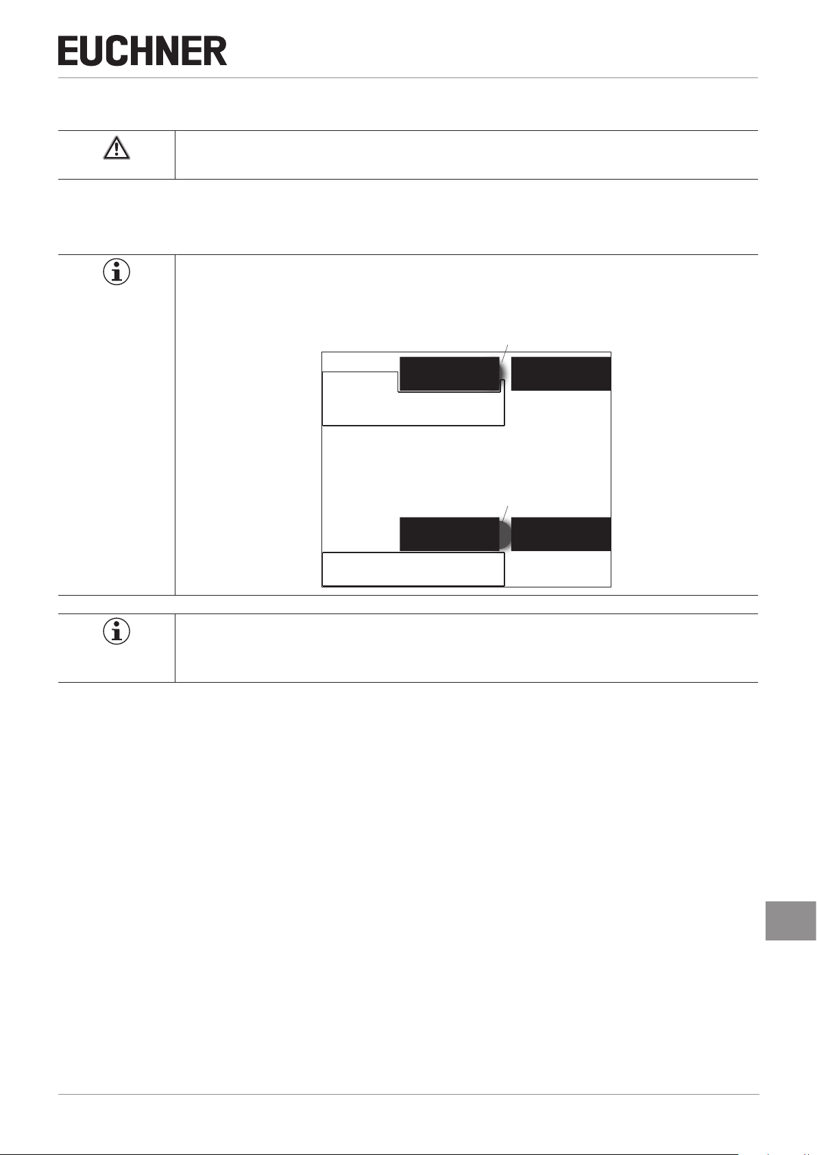
6. Control of guard locking
By changing the parameters in the conguration tool of your control system, it can be set whether bit O 0.0 (in the safe
data block for the MGB locking module) is evaluated as well (see chapter 13.7.4. Data block for MGB locking module L2
on page 26).
The guard locking solenoid is controlled if
Ì bit O 0.0 OR bit SO 0.0 = 1
Truth table:
PROFINET bit PROFIsafe bit Guard locking with
O 0.0 SO 0.0
0 0 inactive
0 1 active
1 0 active
1 1 active
MGB-L2…
2123622-04-06/19 (translation of the original operating instructions)
EN
9
Page 10
Operating Instructions Safety Systems
MGB-L..B-PN.-… (PROFINET) and With Expanded Data Structure Type C
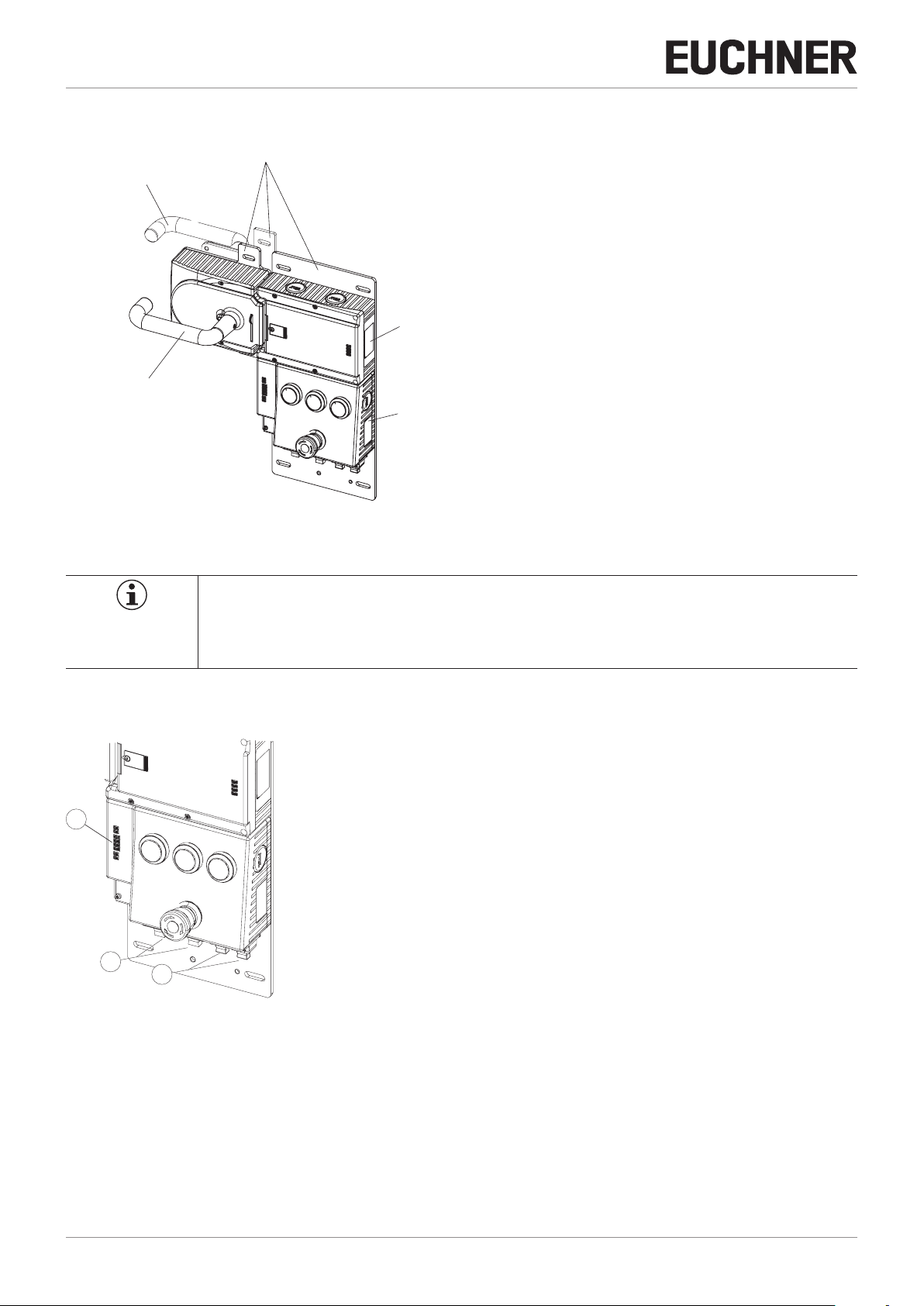
7. System overview
Mounting plate
Escape release (optional)
(MGB-E…)
Evaluation module
(MGB-L…)
Handle module
(MGB-H…)
Bus module
(Pronet)
(MGB-B…)
Figure 1: Components at a glance
NOTICE
MGB-PN systems are completely factory congured. The conguration must not be changed subsequently. The illustrations in this chapter can deviate from your system and serve only as examples. The
conguration of your MGB system can be found in the data sheet included with every MGB system.
7.1. Bus module MGB-B-…-PN
1
2
3
Key:
1
LED indicator
2
Power supply
3
PROFINET connection
Notice:
Depending on the version, additional controls and indicators may be integrated into
the cover. See enclosed data sheet.
Figure 2: Bus module MGB-B-…-PN (conguration example)
10
(translation of the original operating instructions) 2123622-04-06/19
Page 11

MGB-L..B-PN.-… (PROFINET) and With Expanded Data Structure Type C
7.2. Evaluation module MGB-L.-
1
Operating Instructions Safety Systems
2
3
4
Figure 3: Evaluation module MGB-L.-
7.3. Handle module MGB-H-…
1
2
3
4
Figure 4: Handle module MGB-H-…
3
Key:
1
LED indicator
2
Cover for mechanical release
3
Locking arm (only for version with guard locking)
4
Auxiliary marking for max. permitted mounting distance
Notice:
Depending on the version, additional controls and indicators may be integrated into
the cover. See enclosed data sheet.
Key:
1 Door handle
2 Locking screws T10 for housing cover and handle adjustment
3 Fold-out locking mechanism
(optional: second, automatically extending lockout mechanism)
4 Bolt tongue
Notice:
Depending on the version, a mounting plate can be included.
See enclosed data sheet.
7.4. Escape release MGB-E-... (optional)
Key:
1 2 3 4
1 Door handle
2 Housing
3 Actuation axis 8 x 8 mm
(different lengths available)
4 Protective sleeve
Notice:
Depending on the version, a mounting plate can be included.
See enclosed data sheet.
Figure 5: Escape release MGB-E-...
7.5. Dimension drawing
See enclosed data sheet.
7.6. Manual release
Some situations require guard locking to be released manually (e.g. malfunctions or an emergency). A function test should
be performed after release.
More information on this topic can be found in the standard ENISO14119:2013, section 5.7.5.1. The device can feature
the following release functions:
EN
2123622-04-06/19 (translation of the original operating instructions)
11
Page 12
Operating Instructions Safety Systems
MGB-L..B-PN.-… (PROFINET) and With Expanded Data Structure Type C
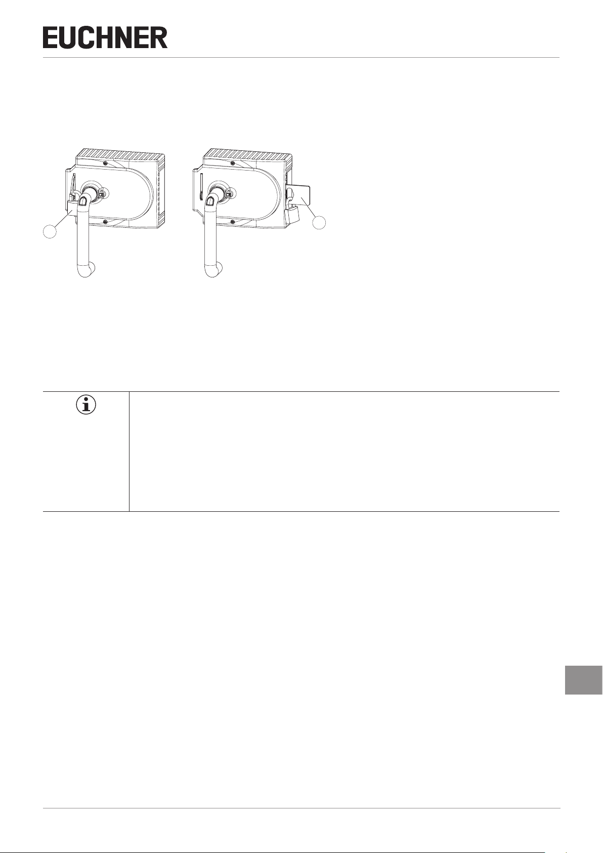
7.7. Mechanical release
In the event of service, the guard locking can be released with the mechanical release irrespective of the state of the solenoid (see Figure 6).
Important!
Ì The system enters into a latching fault when the mechanical release is actuated. See System sta-
tus table, signal sequence incorrect status (DIA red, Lock ashes 1 time).
Ì The system might not enter into a latching fault if the mechanical release is actuated very slowly.
Important!
Ì The mechanical release is not a safety function.
Ì The machine manufacturer must select and use a suitable release (escape release, emergency
unlocking, etc.) for a specic application. A risk assessment is required for this purpose. It may be
necessary to take specications from a product standard into account.
Ì The correct function must be checked at regular intervals.
Ì Loss of the release function due to mounting errors or damage during mounting. Check the re-
lease function every time after mounting.
Ì Please observe the notes on possibly enclosed data sheets.
The locking screw must be screwed back in and sealed (for example with sealing lacquer) after assembly and after every
use of the mechanical release. Tightening torque 0.5 Nm.
1. Undo locking screw.
2. Lift locking arm using a screwdriver and actuate door handle.
Figure 6: Mechanical release
12
(translation of the original operating instructions) 2123622-04-06/19
Page 13
Operating Instructions Safety Systems
MGB-L..B-PN.-… (PROFINET) and With Expanded Data Structure Type C
7.8. Lockout mechanism
If the lockout mechanism is pivoted out/extended, the bolt tongue cannot be extended. The lockout mechanism can be
secured with padlocks (see Figure 7).
¨ To pivot out, press the grooved part (only possible with bolt tongue retracted).
Key:
1
Padlock ∅min. 2mm, ∅max. 10 mm
1
2
Figure 7: Lockout mechanism secured with padlock
Notice:
You can t a maximum of 3 locks Ø8mm.
2
Automatically extending, second lockout mechanism
Padlock ∅min. 6mm, ∅max. 10 mm
7.9. Escape release (optional)
The escape release is used to open a locked safety guard from the inside without tools.
The system enters into a latching fault when the escape release is actuated.
See chapter 15. System status table on page 38, signal sequence incorrect status (DIA red, Lock ashes 1 time).
The system might not enter into a latching fault if the escape release is actuated very slowly.
Important!
Ì It must be possible to operate the escape release manually from inside the protected area without
tools.
Ì It must not be possible to reach the escape release from the outside.
Ì The actuator must not be under tensile stress during manual release.
Ì The escape release meets the requirements of Category B according to EN ISO 13849-1:2008.
Ì The correct function must be checked at regular intervals.
Ì Please observe the notes on possibly enclosed data sheets.
Ì Fit escape release such that operation, inspection and service are possible.
Ì The actuation axis for the escape release must be inserted min. 10 mm into the handle module. Note the information on
the different prole widths in the next chapter.
Ì Align escape release axis at right angles to the handle module. See Figure 8.
2123622-04-06/19 (translation of the original operating instructions)
EN
13
Page 14

Operating Instructions Safety Systems
MGB-L..B-PN.-… (PROFINET) and With Expanded Data Structure Type C
7.9.1. Preparing escape release
Prole width Length required for actuation
D D+9 D+17
30 mm 39 mm 47 mm Standard escape release
40 mm 49 mm 57 mm Standard escape release
45 mm 54 mm 62 mm Standard escape release
50 mm 59 mm 67 mm Standard escape release
axis
Without
mounting
plates
With mounting
plates
(4 mm each)
Example without mounting plates:
Which EUCHNER parts are required? Necessary work steps
with 107 mm axis
(order no. 100465)
with 107 mm axis
(order no. 100465)
If necessary,
extended actuation axis (order no. 106761)
with 107 mm axis
(order no. 100465)
and
extended actuation axis (order no. 106761)
with 107 mm axis
(order no. 100465)
and
extended actuation axis (order no. 106761)
Shorten to required length
Without mounting plates:
None
With mounting plates:
Use extended actuation axis and protective sleeve and
shorten to required length
Use extended actuation axis and protective sleeve and
shorten to required length
Use extended actuation axis and protective sleeve and
shorten to required length
Actuation axis Protective sleeve
M4
Escape release
250
D
Handle module
(11,5) 55,5
A
1
4
2
3
1
Insert actuation axis. The snap ring A must be in contact with the escape release B.
2
Fit door handle.
3
Tighten xing screw to 2Nm and press in cap.
4
Fit protective sleeve.
55,5
D + 9
(+4 mm per mounting plate)
182
D -1
(+4 mm per mounting plate)
B
Figure 8: Preparing escape release
14
(translation of the original operating instructions) 2123622-04-06/19
Page 15
Operating Instructions Safety Systems
MGB-L..B-PN.-… (PROFINET) and With Expanded Data Structure Type C
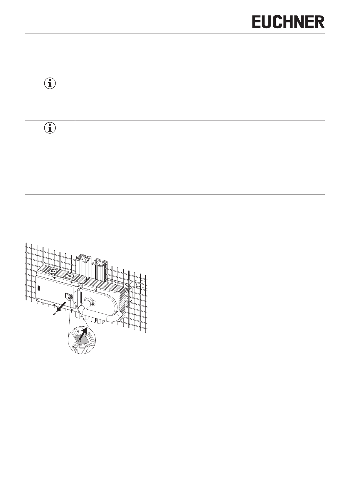
8. Mounting
WARNING
Mounting must be performed only by authorized personnel.
With two-wing hinged doors, one of the two door wings additionally must be latched mechanically.
Use a rod latch (Item) or a double-door lock (Bosch Rexroth) for this purpose, for example.
Important!
Ì If installed ush, the switching distance changes as a function of the installation depth and the
safety guard material.
Operating distance
Locking
module
Flush mounting
Operating distance
Locking
module
Surface mounting
Tip!
Handle
module
Handle
module
Ì You can nd an animation on the mounting process at www.mgb.euchner.de.
Ì The color and labeling of pushbuttons and indicators can be modied.
For mounting steps, see Figure 9 and Figure 10 to Figure 15.
Attach system such that operation of the mechanical release as well as inspection and maintenance are possible.
The locking screw of the mechanical release must be returned to its original position and sealed before putting into operation
(for example with sealing lacquer).
2123622-04-06/19 (translation of the original operating instructions)
EN
15
Page 16

Operating Instructions Safety Systems
MGB-L..B-PN.-… (PROFINET) and With Expanded Data Structure Type C
Figure 9: Installation example for door hinged on the right (general view)
8.1. Mounting color cover
Mounting
1
Removing
2
90°
Click!
3
Color cover
1 2
16
(translation of the original operating instructions) 2123622-04-06/19
Page 17

Operating Instructions Safety Systems
MGB-L..B-PN.-… (PROFINET) and With Expanded Data Structure Type C
9. Changing actuating direction
(here: from right to left)
Important!
It is only possible to make this change when the bolt tongue is not extended and an escape release
is not yet mounted.
As supplied, the handle module is set either for doors hinged on the right or for doors hinged on the left.
Based on the example of a handle module for doors hinged on the right this means:
Ì The safety guard opens by pressing down the door handle.
Ì The system is mounted the other way around for doors hinged on the left. In other words, the safety guard is opened by
pressing up the door handle (see Figure 10). For this reason the actuating direction of the door handle must be changed
(see Figure 10 to Figure 15).
(Similarly on handle modules for doors hinged on the left.)
OPEN
CLOSED
1
Press door handle up.
1
Figure 10: Changing actuating direction, step
4
5
1
3
2
2
Unscrew locking screws.
3
Push cover aside.
Figure 11: Changing actuating direction, steps 2 and
3 mm
6
b
a
7
3
4
Lift the locking pin on the door handle using a screwdriver and hold
it in this position.
5
Turn door handle to the right.
Figure 12: Changing actuating direction, steps 4 and
2123622-04-06/19 (translation of the original operating instructions)
5
8
6
Only if using an escape release: using the hexagon head screw,
turn the joint counterclockwise from position (a) to position (b).
7
Close cover.
8
Screw in locking screws and tighten them to 0.8 Nm.
Figure 13: Changing actuating direction, steps 6 to
EN
8
17
Page 18

Operating Instructions Safety Systems
MGB-L..B-PN.-… (PROFINET) and With Expanded Data Structure Type C
3 mm
11
9
10
9
Remove cover and undo hexagon socket head screw.
AT
Reposition door handle 90° in clockwise direction and fasten again.
A
Tighten hexagon socket head screw to 3 Nm.
Figure 14: Changing actuating direction, steps 9 and
A
State after repositioning.
A
Figure 15: Changing actuating direction, nal state
10. Protection against environmental effects
CLOSED
OPEN
Lasting and correct safety function requires that the system must be protected against foreign bodies such as swarf, sand,
blasting shot, etc., which can become lodged in the locking and handle modules. For this purpose a suitable installation
position should be selected.
Cover device during painting work!
18
(translation of the original operating instructions) 2123622-04-06/19
Page 19

11. Controls and indicators
Operating Instructions Safety Systems
MGB-L..B-PN.-… (PROFINET) and With Expanded Data Structure Type C
LEDs on the bus module
LED Color Description
Link 1 and
Link 2
Data 1 and
Data 2
SF Red System error:
BF Red Bus error:
ON Green Self-test OK: stati-
UB Green Power supply OK:
Green Bus plug inserted:
statically on
Yellow Data transfer:
ashing
statically on
(see chapter on diagnostic messages of
the MGB system)
statically on
(see chapter on diagnostic messages of
the MGB system)
cally on
User passivated:
ashing
statically on
Link1
Data1
Link2
Data2
SF
BF
ON
UB
Binary coding of the DIP
switches for PROFIsafe
address (factory setting:
135)
124816
361 2
4
256
512
51 2 3 4
128
64
32
ON
OFF
OFF
ON
default address:
128 + 4 + 2 + 1 = 135
LEDs on evaluation module
see System status table
Lock
DIA
State
Power
Cover for DIP switches
Link
1
Data
1
Link
2
Data
2
SF
BF
ON
U
B
DIP switches for PROFIsafe address
For coding see above
DC24V DC24V
X1 X3 X4
X2
PN1PN2
6
51 23 4
12
3
4
Figure 16: Displays and controls/binary coding of the DIP switches for PROFIsafe address (factory setting: 135)
EN
2123622-04-06/19 (translation of the original operating instructions)
19
Page 20

Operating Instructions Safety Systems
MGB-L..B-PN.-… (PROFINET) and With Expanded Data Structure Type C
12. Electrical connection
WARNING
In case of an error, loss of the safety function through incorrect connection.
Ì Mounting must be performed only by authorized personnel.
CAUTION
Risk of damage to equipment or malfunctions as a result of incorrect connection.
Ì All the electrical connections must either be isolated from the mains supply by a safety trans-
former according EN IEC 61558-2-6 with limited output voltage in the event of a fault, or by other
equivalent isolation measures.
Ì Power devices which are a powerful source of interference must be installed in a separate location
away from the input and output circuits for signal processing. The cable routing for safety circuits
should be as far away as possible from the cables of the power circuits.
Ì In order to avoid EMC interference, follow EMC notes on devices in the immediate vicinity of the
MGB system and their cables.
Ì In order to avoid EMC interference, the physical environmental and operating conditions at the
installation site of the device must comply with the requirements according to the standard DIN
EN60204-1:2006, section 4.4.2 /EMC).
Important!
Ì The supply for further users on the bus may be forwarded via the Euchner MGB system. The entire
supply current through the MGB must not be higher than specied in the chapter 16. Technical
data on page 39.
Ì The function earth must be connected. An M6 threaded bore is available on the mounting plate
for this purpose.
Ì If the device does not appear to function when operating voltage is applied (e.g. UB LED does not
illuminate), the safety switch must be returned unopened to the manufacturer.
Ì To ensure the stated degree of protection IP67 is achieved, the cover screws must be tightened to
a tightening torque of 1 Nm.
Ì Tighten screw for the cover of the mechanical release to 0.5 Nm.
20
(translation of the original operating instructions) 2123622-04-06/19
Page 21

12.1. Notes about
Important!
Operating Instructions Safety Systems
MGB-L..B-PN.-… (PROFINET) and With Expanded Data Structure Type C
Ì For use and operation as per the requirements
1)
, a power supply with the feature “for use in
class 2 circuits” must be used. The same requirement applies to the safety outputs. Alternative
solutions must comply with the following requirements:
a) Electrically isolated power supply unit with a max. open-circuit voltage of 30V/DC and a
limited current of max. 8A.
b) Electrically isolated power supply unit in combination with fuse as per UL248. This fuse
should be designed for max. 3.3A and should be integrated into the 30VDC voltage section.
Ì The mounting of conduits directly on the MGB is not allowed. Cables are only allowed to be
connected via suitable cable glands. For this purpose use EUCHNER cable gland of type EKPM20/06U. Equivalent cable glands can be used if they are UL-listed (QCRV) and are suitable for the
related cable diameter (22 AWG – 17 AWG).
1) Note on the scope of the UL approval: Only for applications as per NFPA 79 (Industrial Machinery).
The devices have been tested as per the requirements of UL508 (protection against electric shock and re).
12.2. Connections on bus module
The bus module includes the PROFINET connections (X3 and X4) and the power supply connections (X1 and X2). Connection
is performed via push-pull plugs according to IEC61076-3-117, variant 14.
The bus module includes a PROFINET RT switch for Ethernet connection.
12.2.1. Terminal assignment for version with push-pull plugs
Pin Description
X1.1 L1 operating voltage DC 24 V
X1.2 N1 operating voltage 0 V
X1.3 L2 auxiliary voltage* DC 24 V
X1.4 N2 auxiliary voltage* 0 V
X1.5 Function earth
* The auxiliary voltage is not required for the MGB
system
Pin Description
X2.1 L1 operating voltage DC 24 V
X2.2 N1 operating voltage 0 V
X2.3 L2 auxiliary voltage* DC 24 V
X2.4 N2 auxiliary voltage* 0 V
X2.5 Function earth
X1 X2 X3 (PN2) X4(PN1)
1 2 34 5 1
1L+ 2L+
2 3 4 5
1L+
2L+
8 1 8 1
RJ45
Pin Description
X3.1 Receive Data RD+
X3.2 Receive Data RDX3.3 Transmit Data TD+
X3.4 n.c.
X3.5 n.c.
X3.6
Transmit Data TDX3.7 n.c.
X3.8 n.c.
Pin Description
X4.1 Receive Data RD+
X4.2 Receive Data RDX4.3 Transmit Data TD+
X4.4 n.c.
X4.5 n.c.
X4.6
Transmit Data TDX4.7 n.c.
X4.8 n.c.
2123622-04-06/19 (translation of the original operating instructions)
EN
21
Page 22

Operating Instructions Safety Systems
MGB-L..B-PN.-… (PROFINET) and With Expanded Data Structure Type C
13. Setup
13.1. Integrating into PROFINET and PROFIsafe
NOTICE
The parameters “Update time” and “F-WD-Time” have a decisive effect on the reaction time of the
safety function. The safety function could be lost if the reaction times are too long.
Important!
You will require the corresponding GSD le in GSDML format in order to integrate the MGB system:
Ì GSDML-Vx.x-EUCHNER-MGB-PN_D_110026-JJJMMTT.xml
You can nd the GSD le in the download area at www.EUCHNER.de.
Prior to commissioning, the GSD le must be imported into the conguration software of the control
system (see control system manual).
You must perform the following steps to integrate the MGB system into PROFINET:
1. Congure the MGB system with the conguration software of the control system and assign parameters.
The following PROFINET parameters must be set:
Ì Device name (factory setting from GSD le): [euchnermgb].
Ì IP address: optionally xed or dynamic
Ì Update time
Recommendation [32 ms]
Maximum value [128 ms]
(with number of repeat cycles = 3)
The following PROFIsafe parameters must be set:
Ì F_dest_adr (PROFIsafe address): this is generally assigned automatically by the control system.
Ì F_WD_Time (time during which the control system expects a response by the PROFIsafe device): [xxx ms]. Factory set-
ting from GSD le: [600 ms]
2. Set the PROFIsafe address (F_dest_adr) on the MGB system using the DIP switches (see Figure 16 on page 19).
Important: Identical addresses must be set in the control system and on the device.
3. Save the conguration and transfer it to the MGB system.
13.2. Replacement of an MGB system without programming device
If servicing is required, the MGB system is easy to replace with a new one. For this purpose, the following prerequisites
must be met:
Ì The DIP switch settings (PROFIsafe address) on the new device must match those on the old device.
Ì Your Pronet master must support the automatic replacement of Pronet users.
Ì Your Pronet topology must be correctly congured.
Ì The replacement device must be connected to the same port as its predecessor.
Ì There must be no device name in the MGB system.
This eld is empty in the as-delivered state. Systems that already contain a name must rst be reset to the factory settings.
Once these conditions are met, simply replace the old system with the new system.
The Pronet bus does not need to be switched off for this purpose.
13.3. System reset to factory settings
You will nd detailed instructions in the manual for the conguration software for your control system.
22
(translation of the original operating instructions) 2123622-04-06/19
Page 23

Operating Instructions Safety Systems
MGB-L..B-PN.-… (PROFINET) and With Expanded Data Structure Type C
13.4. Mechanical function test
It must be possible to easily insert the bolt tongue in the locking module. To check, close safety guard several times and
actuate door handle.
If available, check function of the escape release. With active guard locking it must be possible to operate the escape release
from the inside without excessive force (approx. 40 N).
13.5. Electrical function test
1. Switch on operating voltage.
2. Close all safety guards and insert the bolt tongue into the locking module.
In case of guard locking by solenoid force ¨ activate guard locking.
Ì The machine must not start automatically.
Ì It must not be possible to open the safety guard.
Ì The yellow STATE LED illuminates continuously.
3. Enable operation in the control system.
Ì It must not be possible to deactivate guard locking as long as operation is enabled.
4. Disable operation in the control system and deactivate guard locking.
Ì The safety guard must remain locked until there is no longer any risk of injury.
Ì It must not be possible to start the machine as long as the guard locking is deactivated.
Ì It must be possible to open the safety guard.
Repeat steps 2-4 for each safety guard.
2123622-04-06/19 (translation of the original operating instructions)
EN
23
Page 24

Operating Instructions Safety Systems
MGB-L..B-PN.-… (PROFINET) and With Expanded Data Structure Type C
13.6. PROFINET data bytes for “standard” and “expanded” data structures (data blocks
for non-safety-related functions)
Important!
This device can be operated either in the “standard” or in the “expanded” conguration. Additional
functions are available in the “expanded” conguration (see chapter 13.7.3. Additional button functions
(only for conguration with expanded data structure) on page 26).
Select one of the congurations by bringing together the corresponding modules via drag & drop in
the conguration software of your control system.
The modules are easy to distinguish with the aid of the comment block. Plug-in standard modules
and expanded modules must not be mixed. The modules must be selected before the rst Power On
process. Another Power On process is necessary in case of exchanging.
The following modules can be present in various combinations in an MGB system:
Ì Bus module MGB-B-…PN (contains everything required for the PROFINET connection)
Ì Locking module MGB-L. (forms the door locking mechanism together with the handle module)
Each MGB module occupies a certain number of PROFINET data bytes in the input and output range of the control system.
The PROFINET data bytes for every MGB module or also individual functions are combined in data blocks (see tables below).
A distinction is made between the following data block types:
Ì Data blocks for MGB modules
Ì Data blocks for individual functions
These data blocks are automatically assigned to the designated slots in the conguration software of the control system
when your MGB system is placed. This assignment changes according to MGB system. The exact assignment of the slots
and the exact bit allocation for your device can be seen in the data sheet. The data sheet is included with every MGB system.
13.7. Data blocks for MGB modules
All standard functions of an MGB module are combined in these data blocks. Additional functions, e.g. an optional enabling
switch or a stacklight, have separate data ranges (see chapter 13.8. Data blocks of individual functions at a glance on
page 27).
24
(translation of the original operating instructions) 2123622-04-06/19
Page 25

MGB-L..B-PN.-… (PROFINET) and With Expanded Data Structure Type C
X1
X2
X1
X2
13.7.1. Data block for “standard” MGB bus module
Operating Instructions Safety Systems
MGB module Slot
Bus module
(conguration example)
S90 S92S91
1
Link
1
Data
Link
2
Data
2
SF
BF
ON
U
B
S94
V42CD1
NP3X
Input range
(2 bytes)
NP4XV42CD2
Output range
(1 byte)
See data sheet for slot assignment
Required memory in data range of the control system (IO controller)
(refer to the data sheet of your device for the exact bit allocation)
Switch - - - - - S92 S91 S90
I0.7 I0.6 I0.5 I0.4 I0.3 I0.2 I0.1 I0.0
Bit
I1.7 I1.6 I1.5 I1.4 I1.3 I1.2 I1.1 I1.0
Display - - - - - H92 H91 H90
Bit
O0.7 O0.6 O0.5 O0.4 O0.3 O0.2 O0.1 O0.0
Bit allocation for 1st byte
Bit Description
I0.0
I0.1 O0.1
Depends on your conguration variant (refer to the data
sheet of your device for the exact bit allocation)
I0.2 O0.2
I0.3 O0.3
I0.4 O0.4
Input range
I0.5 O0.5
I0.6 O0.6
I0.7 O0.7
Bit allocation for 2nd byte
Bit Description
I1.0
I1.1
Depends on your conguration variant (refer to the data
sheet of your device for the exact bit allocation)
I1.2
I1.3
I1.4
Input range
I1.5
I1.6
I1.7
Bit Description
O0.0
Depends on your conguration variant (refer to the data
Output range
sheet of your device for the exact bit allocation)
13.7.2. Data block for “expanded” MGB bus module
MGB module Slot
Bus module
(conguration example)
Input range
(1 byte)
1
Link
1
Data
Link
2
Data
2
SF
BF
ON
U
B
S90 S92S91
S94
Output range
V42CD1
NP4XV42CD2
NP3X
(1 byte)
See data sheet for slot assignment
Bit Description
I0.0
I0.1 O0.1
Depends on your conguration variant (refer to the data
sheet of your device for the exact bit allocation)
I0.2 O0.2
I0.3 O0.3
I0.4 O0.4
Input range
I0.5 O0.5
I0.6 O0.6
I0.7 O0.7
Required memory in data range of the control system (IO controller)
(refer to the data sheet of your device for the exact bit allocation)
Switch - - - - - S92 S91 S90
Bit
Display - - - - - H92 - H90
Bit
Bit allocation for 1st byte
I0.7 I0.6 I0.5 I0.4 I0.3 I0.2 I0.1 I0.0
O0.7 O0.6 O0.5 O0.4 O0.3 O0.2 O0.1 O0.0
Bit Description
O0.0
Depends on your conguration variant (refer to the data
sheet of your device for the exact bit allocation)
Output range
EN
2123622-04-06/19 (translation of the original operating instructions)
25
Page 26

Operating Instructions Safety Systems
MGB-L..B-PN.-… (PROFINET) and With Expanded Data Structure Type C
13.7.3. Additional button functions (only for conguration with expanded data structure)
Lamp control with MGB-PN in expanded mode
Lamp Color ON OFF Flashing
H90 White Bit H90 = 1 Bit H90 = 0 -
White
Blue
H91
Yellow
Green
H92
H94 Red
White Bit H92 = 0 -
Blue Bit H92 = 1 -
Door closed and
acknowledged
Door closed and locked via
bit from standard area and
acknowledged
Door closed and locked
via bit from safe area and
acknowledged
Door closed and locked
via bit from safe area and
from standard area and
acknowledged
Bit H94=1 and emergency
stop not pressed and
acknowledged
Door open
All other states -
All other states -
All other states -
Bit H94 = 0 and emergency
stop not pressed and
acknowledged
Door closed and not
acknowledged or escape
release operated
Emergency stop pressed
13.7.4. Data block for MGB locking module L2
MGB module Slot
Locking module
(conguration example)
-S7
Bit Description
I0.0
T (door position)
I0.1
R (bolt position)
I0.2
Z (guard locking)
I0.3
I0.4
I0.5
I0.6
I0.7
n.c.
n.c.
n.c.
SK (T AND R)
ÜK (T AND R AND Z)
Input range
signment
See data sheet for slot as-
Input range
(1 byte)
Output range
(1 byte)
Required memory in data range of the control system (IO controller)
(refer to the data sheet of your device for the exact bit allocation)
Switch ÜK SK - - - Z R T
Bit
Display - - - - - - -
Bit
I0.7 I0.6 I0.5 I0.4 I0.3 I0.2 I0.1 I0.0
O0.7 O0.6 O0.5 O0.4 O0.3 O0.2 O0.1 O0.0
Bit allocation
Bit Description
O0.0
S, guard locking solenoid – control voltage on
(function identical to bit SO0.0 => but control from PROFINET
area)
O0.1
n.c.
O0.2
n.c.
O0.3
O0.4
O0.5
O0.6
O0.7
n.c.
n.c.
n.c.
n.c.
n.c.
Output range
Guard
locking
solenoid
26
(translation of the original operating instructions) 2123622-04-06/19
Page 27

Operating Instructions Safety Systems
MGB-L..B-PN.-… (PROFINET) and With Expanded Data Structure Type C
13.8. Data blocks of individual functions at a glance
Function data blocks are required for all additional functions that are not included in the data blocks for MGB modules.
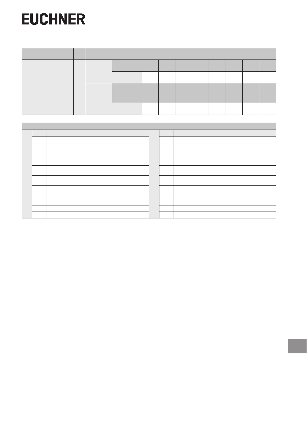
13.8.1. Data block for “standard” emergency stop function
Function Slot
Emergency stop
Bit Description
I0.0
Emergency stop auxiliary contact
I0.1
n.c.
I0.2
Input range
I0.3
I0.4
I0.5
I0.6
I0.7
n.c.
n.c.
n.c.
n.c.
n.c.
n.c.
ment
See data sheet for slot assign-
Input range
(1 byte)
Output range
(1 byte)
Required memory in data range of the control system (IO controller)
(refer to the data sheet of your device for the exact bit allocation)
Switch - - - - - - -
Bit
Display - - - - - - -
Bit
I0.7 I0.6 I0.5 I0.4 I0.3 I0.2 I0.1 I0.0
O0.7 O0.6 O0.5 O0.4 O0.3 O0.2 O0.1 O0.0
Bit allocation
Bit Description
O0.0
Emergency stop lighting.
For “standard” conguration:
control via this bit. 1 = ON, 0 = OFF
For “expanded” conguration:
controlled via the integrated lamp control system (in slot “expanded PROFISafe 32 Bool IO”). See 13.7.3. Additional button
functions (only for conguration with expanded data structure) on
page 26
O0.1
n.c.
O0.2
O0.3
O0.4
O0.5
O0.6
O0.7
n.c.
n.c.
n.c.
n.c.
n.c.
n.c.
Output range
S94
(auxiliary
contact)
H94
(LED)
2123622-04-06/19 (translation of the original operating instructions)
EN
27
Page 28

Operating Instructions Safety Systems
X2
X2
MGB-L..B-PN.-… (PROFINET) and With Expanded Data Structure Type C
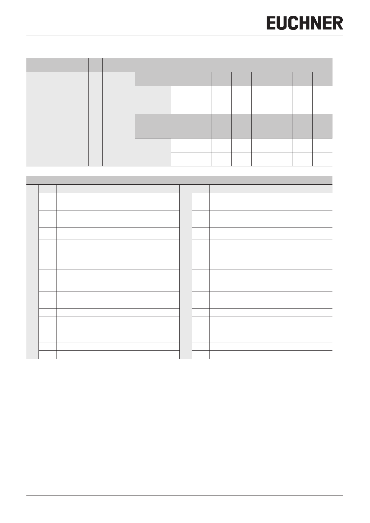
13.8.2. Data block for “standard” enabling switch function (optional)
Function Slot
Enabling switch
V42CD1
CD2X
X14
Input range
(1 byte)
assignment
Output range
(1 byte)
See data sheet for slot
Required memory in data range of the control system (IO controller)
(refer to the data sheet of your device for the exact bit allocation)
Function - ES - ES + - - - -
Bit
I0.7 I0.6 I0.5 I0.4 I0.3 I0.2 I0.1 I0.0
Display - - - - - -
Bit
O0.7 O0.6 O0.5 O0.4 O0.3 O0.2 O0.1 O0.0
Bit allocation
Bit Description
I0.0
Enabling switch in “enabling” position (auxiliary contact)
I0.1
n.c.
I0.2
n.c.
I0.3
n.c.
I0.4
Input range
n.c.
I0.5
Enabling switch ES+ button
I0.6
Enabling switch ES- button
I0.7
n.c.
Bit Description
O0.0
Enabling switch illumination for + button
O0.1
Enabling switch illumination for - button
O0.2
n.c.
O0.3
n.c.
O0.4
O0.5
O0.6
O0.7
n.c.
n.c.
n.c.
n.c.
Output range
13.8.3. Data block for “expanded” enabling switch function (optional)
Function Slot
Enabling switch
V42CD1
CD2X
Input range
(1 byte)
Required memory in data range of the control system (IO controller)
(refer to the data sheet of your device for the exact bit allocation)
Function - - ES (S1) - - - -
Bit
I0.7 I0.6 I0.5 I0.4 I0.3 I0.2 I0.1 I0.0
ES -
(LED)
ES (enabling)
ES +
(LED)
ES (enabling)
X14
assignment
Output range
(1 byte)
See data sheet for slot
Display - - - - - - LED P1 LED S1
Bit
O0.7 O0.6 O0.5 O0.4 O0.3 O0.2 O0.1 O0.0
Bit allocation
Bit Description
I0.0
Enabling switch in “enabling” position (auxiliary contact)
Bit Description
O0.0
Enabling switch illumination
With “expanded” conguration:
controlled via the integrated lamp control system See 13.8.4.
Additional button functions (only for conguration with expanded
data structure) on page 28
I0.1
I0.2
I0.3
Input range
I0.4
I0.5
I0.6
I0.7
n.c.
n.c.
n.c.
n.c.
Enabling switch S1 button
n.c.
n.c.
O0.1
O0.2
O0.3
Output range
O0.4
O0.5
O0.6
O0.7
see above
n.c.
n.c.
n.c.
n.c.
n.c.
n.c.
13.8.4. Additional button functions (only for conguration with expanded data structure)
Lamp control in enabling switch for MGB-PN in expanded mode
Lamp Color ON OFF Flashing
ES+ Red Enabling switch inserted Enabling switch not inserted -
ES- Yellow
Enabling switch inserted and
pressed and acknowledged
Enabling switch not pressed or
enabling switch not inserted
Enabling switch inserted
and pressed and not
acknowledged
28
(translation of the original operating instructions) 2123622-04-06/19
Page 29
MGB-L..B-PN.-… (PROFINET) and With Expanded Data Structure Type C
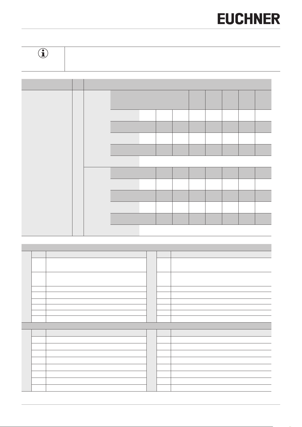
13.8.5. Data block for “standard” diagnostics function
Operating Instructions Safety Systems
Function Slot
Diagnostics
Bit Description
I0.0
Device diagnostics (PROFIsafe error #72): message present.
Diagnostic code: see table of device-specic messages.
I0.1
Device diagnostics, device-specic message 274(4) “Plausibility
check found an error (e.g. escape release actuated)”
I0.2
Device diagnostics, device-specic message 272(1) or 273(1)
“Fault in emergency stop”
I0.3
Device diagnostics, device-specic message 272(2) or 273(2)
Input range
“Fault in enabling switch”
I0.4
Device diagnostics, device-specic message 272(3,4,5),
273(3,4,5)
“Fault in locking module”
I0.5
n.c.
I0.6
n.c.
I0.7
Mechanical life > 1 million operating cycles
ment
See data sheet for slot assign-
Input range
(1 byte)
Output range
(1 byte)
Required memory in data range of the control system (IO controller)
Message
Bit
Acknowledg-
ment
Bit
(see below for exact bit allocation)
Mechan-
ical life
I0.7 I0.6 I0.5 I0.4 I0.3 I0.2 I0.1 I0.0
- - - - - -
O0.7 O0.6 O0.5 O0.4 O0.3 O0.2 O0.1 O0.0
Bit allocation
- -
Bit Description
O0.0
Device diagnostics: Acknowledge message, acknowledgment of
I0.2, I0.3 or I0.4. I0.0 is also acknowledged if only one
message is present
O0.1
Trigger MGB locking module reset: Acknowledge message,
acknowledgment of I1. I0 is also acknowledged if only one
message is present.
O0.2
n.c.
O0.3
n.c.
Output range
O0.4
n.c.
O0.5
n.c.
O0.6
n.c.
O0.7
n.c.
272(6)
273(6)
272(2)
273(2)
272(1)
273(1)
274(4) 72
Reset
MGB
Ac-
knowl-
edg-
ment
2123622-04-06/19 (translation of the original operating instructions)
EN
29
Page 30
Operating Instructions Safety Systems
MGB-L..B-PN.-… (PROFINET) and With Expanded Data Structure Type C
13.8.6. Data block for “expanded” diagnostics function
Function Slot
Diagnostics
Bit Description
I0.0
Device diagnostics (PROFIsafe error #72): message present.
Diagnostic code: see table of device-specic messages.
I0.1
Device diagnostics, device-specic message 274(4) “Plausibility
check found an error (e.g. escape release actuated)”
I0.2
Device diagnostics, device-specic message 272(1) or 273(1)
“Fault in emergency stop”
I0.3
Device diagnostics, device-specic message 272 (2,7) or
273(2,7) “Fault in enabling switch”
I0.4
Device diagnostics, device-specic message 272(3,4,5),
273(3,4,5)
“Fault in locking module”
I0.5
n.c.
I0.6
Input range
n.c.
I0.7
Mechanical life > 1 million operating cycles
I1.0
Single diagnostics: door
I1.1
Single diagnostics: bolt
I1.2
Single diagnostics: guard locking
I1.3
n.c.
I1.4
n.c.
I1.5
n.c.
I1.6
n.c.
I1.7
n.c.
Required memory in data range of the control system (IO controller)
Message
Input range
(2 bytes)
Output range
(2 bytes)
See data sheet for slot assignment
Bit
Acknowledg-
ment
Bit
(see below for exact bit allocation)
Mechan-
ical life
I0.7 I0.6 I0.5 I0.4 I0.3 I0.2 I0.1 I0.0
I1.7 I1.6 I1.5 I1.4 I1.3 I1.2 I1.1 I1.0
- - - - - -
O0.7 O0.6 O0.5 O0.4 O0.3 O0.2 O0.1 O0.0
O1.7 O1.6 O1.5 O1.4 O1.3 O1.2 O1.1 O1.0
Bit allocation
- -
Bit Description
O0.0
Device diagnostics: Acknowledge message, acknowledgment of
I0.2, I0.3 or I0.4. I0.0 is also acknowledged if only one
message is present
O0.1
Trigger MGB locking module reset: Acknowledge message,
acknowledgment of I1. I0 is also acknowledged if only one
message is present.
O0.2
n.c.
O0.3
n.c.
O0.4
n.c.
O0.5
n.c.
O0.6
O0.7
O1.0
O1.1
O1.2
O1.3
O1.4
O1.5
O1.6
O1.7
n.c.
n.c.
n.c.
n.c.
n.c.
n.c.
n.c.
n.c.
n.c.
n.c.
Output range
272(6)
273(6)
272(2)
273(2)
272(1)
273(1)
274(4) 72
Reset
MGB
Ac-
knowl-
edg-
ment
30
(translation of the original operating instructions) 2123622-04-06/19
Page 31

Operating Instructions Safety Systems
MGB-L..B-PN.-… (PROFINET) and With Expanded Data Structure Type C
13.9. PROFIsafe data bytes (data block for safe functions)
Safe PROFIsafe data are transmitted in addition to the non-safety-related PROFINET data. These data include all information
about the door position and guard locking, emergency stop and enabling switch, for example.
Important!
This device can be operated either in the “standard” or in the “expanded” conguration. Additional
functions are available in the “expanded” conguration (see chapter 13.7.3. Additional button functions
(only for conguration with expanded data structure) on page 26).
Select one of the congurations by bringing together the corresponding modules via drag & drop in
the conguration software of your control system.
The modules are easy to distinguish with the aid of the comment block. Plug-in standard modules
and expanded modules must not be mixed. The modules must be selected before the rst Power On
process. Another Power On process is necessary in case of exchanging.
13.9.1. “Standard” PROFIsafe data bytes
The “standard” PROFIsafe data block includes all safe functions. It is subdivided as follows:
Ì 2 input bytes of data for the functions (e.g. emergency stop switch position)
Ì 2 additional input bytes (empty)
Ì 4 input bytes used within PROFIsafe
Ì 1 output byte for the functions (e.g. safe control of guard locking)
Ì 1 additional output byte (empty)
Ì 4 output bytes used within PROFIsafe
All data bits are present in parallel in the non-safety-related PROFINET and can be used as signaling bits there.
Important!
Never use the signaling bits for safety functions.
EN
2123622-04-06/19 (translation of the original operating instructions)
31
Page 32
Operating Instructions Safety Systems
MGB-L..B-PN.-… (PROFINET) and With Expanded Data Structure Type C
13.9.2. Data block for “standard” PROFIsafe
Important!
Ì Refer to the data sheet enclosed with your MGB system for the exact bit allocation. Use only bits
that are specied according to the data sheet.
Function Slot
Diagnostics
Required memory in data range of the control system (IO controller)
Function -
1st byte
Input range
(8 bytes)
See data sheet for slot assignment
Output range
(6 bytes)
Function - - - - - - ÜK SK
2nd byte
Function
3rd - 8th bytes
Function - - - - - - -
1st byte
Function - - - - - - - -
2nd byte
Function
(see below for exact bit allocation)
Guard
locking
(Z)
SI0.7 SI0.6 SI0.5 SI0.4 SI0.3 SI0.2 SI0.1 SI0.0
SI1.7 SI1.6 SI1.5 SI1.4 SI1.3 SI1.2 SI1.1 SI1.0
Unused or used within PROFIsafe (control byte, CRC, etc.)
SO0.7 SO0.6 SO0.5 SO0.4 SO0.3 SO0.2 SO0.1 SO0.0
SO1.7 SO1.6 SO1.5 SO1.4 SO1.3 SO1.2 SO1.1 SO1.0
Bolt
position
(R)
Door
position
(T)
ES (en-
abling
switch)
S94
(emergency
stop)
Guard
locking
Bit Description
SI0.0
Emergency stop
SI.01
Enabling switch
Enabling contacts closed (three-stage enabling switch in center
position), no evaluation of the edges
SI0.2
Door position (T)
SI0.3
Input range
Input range
Bolt position (R)
SI0.4
Guard locking (Z)
SI0.5
Operating mode selector switch, 1st bit (here: not used)
SI0.6
Operating mode selector switch, 2nd bit (here: not used)
SI0.7
Operating mode selector switch, 3rd bit (here: not used)
Bit Description
SI1.0
SK (T AND R)
SI1.1
ÜK (T AND R AND Z)
SI1.2
n.c.
SI1.3
n.c.
SI1.4
n.c.
SI1.5
n.c.
SI1.6
n.c.
SI1.7
Reserved for customer-specic function
3rd - 6th bytes
Bit allocation for 1st byte
Bit allocation for 2nd byte
Used within PROFIsafe (control byte, CRC, etc.)
Bit Description
SO0.0
Guard locking solenoid – control voltage on
(function identical to bit O0.0 in data block for MGB evaluation
module L0, L1 or L2 => but with safe control via PROFIsafe)
SO0.1
n.c.
SO0.2
n.c.
SO0.3
Output range
Output range
n.c.
SO0.4
n.c.
SO0.5
n.c.
SO0.6
n.c.
SO0.7
n.c.
Bit Description
SO1.0
n.c.
SO1.1
n.c.
SO1.2
n.c.
SO1.3
n.c.
SO1.4
n.c.
SO1.5
n.c.
SO1.6
n.c.
SO1.7
n.c.
32
(translation of the original operating instructions) 2123622-04-06/19
Page 33

Operating Instructions Safety Systems
MGB-L..B-PN.-… (PROFINET) and With Expanded Data Structure Type C
13.9.3. “Expanded” PROFIsafe data bytes
The “expanded” PROFIsafe data block includes all safe functions. It is subdivided as follows:
Ì 2 input bytes of data for the functions (e.g. emergency stop switch position)
Ì 2 additional input bits (empty)
Ì 4 input bytes used within PROFIsafe
Ì 1 output byte for the functions (e.g. safe control of guard locking)
Ì 1 additional output byte (empty)
Ì 4 output bytes used within PROFIsafe
All data bits are present in parallel in the non-safety-related PROFINET and can be used as signaling bits there.
Important!
Never use the signaling bits for safety functions.
13.9.4. Data block for “expanded” PROFIsafe
Important!
Ì Refer to the data sheet enclosed with your MGB system for the exact bit allocation. Use only bits
that are specied according to the data sheet.
Function Slot
Diagnostics
Required memory in data range of the control system (IO controller)
Function -
1st byte
Function - - - - - - ÜK SK
2nd byte
Input range
(8 bytes)
See data sheet for slot assignment
Function PSÜK - - ZSIN ZSQ ÜKQ SKQ NHQ
3rd byte
Function - - - - - - - -
4th byte
Function
5th - 8th bytes
Function ETR ENR ANH - - -
(see below for exact bit allocation)
Guard
locking
(Z)
SI0.7 SI0.6 SI0.5 SI0.4 SI0.3 SI0.2 SI0.1 SI0.0
SI1.7 SI1.6 SI1.5 SI1.4 SI1.3 SI1.2 SI1.1 SI1.0
SI2.7 SI2.6 SI2.5 SI2.4 SI2.3 SI2.2 SI2.1 SI2.0
SI3.7 SI3.6 SI3.5 SI3.4 SI3.3 SI3.2 SI3.1
Used within PROFIsafe (control byte, CRC, etc.)
Bolt
position
(R)
Door
position
(T)
ES (en-
abling
switch)
Emer-
gency
release
S94
emergency
stop
Guard
locking
SO0.7 SO0.6 SO0.5 SO0.4 SO0.3 SO0.2 SO0.1 SO0.0
SO1.7 SO1.6 SO1.5 SO1.4 SO1.3 SO1.2 SO1.1 SO1.0
Output range
(6 bytes)
1st byte
Function - - - - - - - -
2nd byte
Function
3rd - 6th bytes
2123622-04-06/19 (translation of the original operating instructions)
EN
Used within PROFIsafe (control byte, CRC, etc.)
33
Page 34

Operating Instructions Safety Systems
MGB-L..B-PN.-… (PROFINET) and With Expanded Data Structure Type C
Bit allocation for 1st byte
Bit Description
SI0.0
Emergency stop
SI.01
Enabling switch
Enabling contacts closed (three-stage enabling switch in center
position), no evaluation of the edges
SI0.2
Door position (T)
SI0.3
Bolt position (R)
SI0.4
Guard locking (Z)
SI0.5
Operating mode selector switch, 1st bit
Input range
SI0.6
Operating mode selector switch, 2nd bit
SI0.7
Operating mode selector switch, 3rd bit
Bit Description
SI1.0
SK (T AND R)
SI1.1
ÜK (T AND R AND Z)
SI1.2
n.c.
SI1.3
n.c.
SI1.4
Input range
n.c.
SI1.5
n.c.
SI1.6
n.c.
SI1.7
Reserved for customer-specic function
Bit allocation for 2nd byte
Bit Description
SO0.0
Guard locking solenoid – control voltage on
(function identical to bit O0.0 in data block for MGB evaluation
module L0, L1 or L2 => but with safe control via PROFIsafe)
SO0.1
Emergency release
SO0.2
n.c.
SO0.3
n.c.
SO0.4
n.c.
SO0.5
Emergency stop control (ANH)
If this bit is set, the red lamp is switched on during emergency
stop. Attention: Internal light control is prioritized; see emergency
Output range
Output range
stop lamp.
SO0.6
ENR
If this bit is set, this allows the emergency stop to be acknowledged from the control panel. This is used in parallel with acknowledgment button S91 in the MGB (OR); only the falling edge
is evaluated. This allows all emergency stops to be acknowledged simultaneously from the panel.
SO0.7
ETR
If this bit is set, this allows the SK and the ÜK to be acknowledged from the control system. This is used in parallel with the
acknowledgment button in the MGB (OR); only the falling edge
is evaluated. This used for one-time acknowledgment from the
control system during system start-up.
Bit Description
SO1.0
n.c.
SO1.1
n.c.
SO1.2
n.c.
SO1.3
n.c.
SO1.4
n.c.
SO1.5
n.c.
SO1.6
n.c.
SO1.7
n.c.
34
(translation of the original operating instructions) 2123622-04-06/19
Page 35

Bit Description
SI2.0
NHQ
This is set if bit NH is set
AND
the falling edge is detected on bit S91
OR
the falling edge is detected in bit ENR.
This is reset when the emergency stop button is pressed. Button
S91 (acknowledgment) – button module in bus module
SI2.1
SKQ
This is set if bit SK is set
AND
the falling edge is detected on bit S91
OR
the falling edge is detected in bit ETR.
This is reset when SK switches off
S91 (acknowledgment) – button module in bus module
SI2.2
ÜKQ
Input range
Input range
This is set if bit ÜK is set
AND
the falling edge is detected on bit S91
OR
the falling edge is detected in bit ETR.
This is reset when ÜK switches off.
SI2.3
ZSQ
SI2.4
ZSIN
This is set as long as an enabling switch is inserted and no fault
is present. This is reset when the enabling switch is removed.
SI2.5
n.c.
SI2.6
n.c.
SI2.7
PSÜK
This is set if bit ÜK is set and there is no ZH control in the Prosafe area (control only from Pronet area with bit ZH). This is reset
when ÜK is switched off.
Bit Description
SI3.0
n.c.
SI3.1
n.c.
SI3.2
n.c.
SI3.3
n.c.
SI3.4
n.c.
SI3.5
n.c.
SI3.6
n.c.
SI3.7
n.c.
Operating Instructions Safety Systems
MGB-L..B-PN.-… (PROFINET) and With Expanded Data Structure Type C
Bit allocation for 3rd byte
Bit allocation for 4th byte
2123622-04-06/19 (translation of the original operating instructions)
EN
35
Page 36

Operating Instructions Safety Systems
MGB-L..B-PN.-… (PROFINET) and With Expanded Data Structure Type C
14. Diagnostic messages of the MGB system
All diagnostic messages are listed below. The scope of the possible messages can differ according to the MGB system version.
PROFIsafe messages
Display via LED BF (see Figure 16 on page 19)
No. Description Measures/remedying errors
64 Error when comparing the
PROFIsafe destination address
(F_Dest_Add)
65 Invalid PROFIsafe destination ad-
dress (F_Dest_Add)
66 Invalid PROFIsafe source address
(F_Sourrce_Add)
67 Value for the PROFIsafe time moni-
toring is 0 ms (F_WD_TIME)
68 Parameter F_SIL exceeds SIL of the
device-specic application
69 Parameter F_CRC_Length does not
match the generated values
70 Version for F_Parameter not
correct
71
Error CRC 1- (during booting) 1. Restart system
72 Device-specic diagnostic informa-
tion (see following table)
1. Check DIP switch setting
2. Restart system
1. Check addressing
2. Restart system
1. Check addressing
2. Restart system
1. Check system times
2. Restart system
1. Check settings
2. Restart system
1. Check settings
2. Restart system
1. Check conguration
2. Restart system
1. Identify error via input bit I0.0.
2. For error remedy, see the following table with device-specic
messages
Device-specic diagnostic information
Display via LED SF (see Figure 16 on page 19)
Discrepancy error (two-channel monitoring detected an error)
Note:
Ì The discrepancy time is the maximum time during which channel 1 and
channel 2 may have different signal states.
Ì If acknowledgment was unsuccessful, send the device to the manufac-
turer.
No. Description Measures/remedying errors
272 Discrepancy time exceeded 1. Search for cause
272(1) Emergency-stop discrepancy time
exceeded
272(3) Door position discrepancy time
exceeded
272(4) Bolt-position discrepancy time
exceeded
272(5) Guard-locking discrepancy time 1. Open the door
272(6) Operating mode selector switch 1. Search for cause
272(7) Enabling switch inserted detection
(only with “expanded” conguration)
2. Acknowledge fault (via output
bit O0.0)
1. Press emergency stop
2. Acknowledge fault (via output
bit O0.0)
1. Open the door
2. Acknowledge fault (via output
bit O0.0)
1. Open the door
2. Acknowledge fault (via output
bit O0.0)
2. Acknowledge fault (via output
bit O0.0)
2. Acknowledge fault (via output
bit O0.0)
1. Search for cause
2. Acknowledge fault (via output
bit O0.0)
Test-pulse error (short-circuit monitoring detected an error)
Note:
Ì The emergency stop must not be pressed during acknowledgment.
Ì If acknowledgment was unsuccessful, send the device to the manufac-
turer.
No. Description Measures/remedying errors
273 Test pulses erroneous Safety function is switched off
273(1) Emergency-stop test pulses
erroneous
273(3) Door-position test pulses erro-
neous
273(4) Bolt-position test pulses erroneous Safety function is switched off
273(5) Guard-locking test pulses erro-
neous
273(6) Operating mode selector switch Safety function is switched off
273(7) Enabling switch inserted detection
(only with “expanded” conguration)
while no test pulses are being
detected.
1. Check system
2. Acknowledgment via output bit
O0.0 required.
Safety function is switched off
while no test pulses are being
detected.
1. Check system
2. Acknowledgment via output bit
O0.0 required.
Safety function is switched off
while no test pulses are being
detected.
1. Close door
2. Acknowledgment via output bit
O0.0 required.
while no test pulses are being
detected.
1. Close door
2. Acknowledgment via output bit
O0.0 required.
Safety function is switched off
while no test pulses are being
detected.
1. Close and lock door
2. Acknowledgment via output bit
O0.0 required.
while no test pulses are being
detected.
1. Check system
2. Acknowledgment via output bit
O0.0 required.
Safety function is switched off
while no test pulses are being
detected.
1. Check system
2. Acknowledgment via output bit
O0.0 required.
36
(translation of the original operating instructions) 2123622-04-06/19
Page 37

MGB-L..B-PN.-… (PROFINET) and With Expanded Data Structure Type C
General messages of the overall system
No. Description Measures/remedying errors
Operating Instructions Safety Systems
274 (1) Max. (mech.) life exceeded Message via input bit I0.7
274(2) Internal device error Please contact our support orga-
274(3) Signal sequence erroneous (e.g.
broken bolt tongue recognized)
274(4) Plausibility test detected an error
(e.g. escape release actuated)
Message cannot be reset
nization!
1. Check mech. functions
2. Acknowledge fault (via output
bit O0.1). The safety door
must be open.
Important: The resetting procedure is contained in the chapter
“Latching fault when actuating the
escape release”
Ì Acknowledge fault (via output
bit O0.1)
274(5) Locking module in error Please contact our support orga-
PROFIsafe errors
No. Description Measures/remedying errors
276(1) Starting error PROFIsafe
276(2) Memory error RAM
276(3) Memory error FLASH
276(4) Communication error
276(5) Synchronization error
276(6) Voltage monitoring
nization!
Please contact our support orga-
nization!
General errors of the overall system
No. Description Measures/remedying errors
277(1) Starting error MGB
277(2) Communication error
278 Internal device error
Please contact our support orga-
nization!
Cyclical Prosafe status message
Bit Description Measures/remedying errors
0 Reserved 1 Error in F-Device or F-Module
2 Communication error, CRC error
3 Communication error, watchdog
timeout
4 Fail-safe values activated 5 Toggle bit 6 Consecutive number was reset 7 Reserved -
User is passivated (on LED
ashes).
You will nd information on de-
passivating in the manual for your
control system.
EN
2123622-04-06/19 (translation of the original operating instructions)
37
Page 38

Operating Instructions Safety Systems
MGB-L..B-PN.-… (PROFINET) and With Expanded Data Structure Type C
15. System status table
LEDs on interlocking/locking module
State
LED indicator
Normal operation, door open
Normal operation, door closed
DIA (rd)
Lock (ye)
STATE (gn)
long OFF
short ON
POWER (gn)
input bit I0.7
Device diagnostics
Input bit I0.1
Device diagnostics
Input bit I0.0
Device diagnostics
ÜK input bit SI1.1
long ON
shot OFF
long ON
Normal operation, door closed, bolt tongue inserted
short
OFF
Door open; unit is ready for teach-in for another handle
module (only short time after power-up)
Positive acknowledgment after completion of teach-in
operation
Handle module read error (e.g. error in code or code
cannot be read)**
Signal sequence incorrect
e.g. broken bolt tongue recognized) ***
or after actuation of the escape release, for example*
LED not illuminated
LED illuminated
LED ashes for 8 seconds at 10 Hz
LED ashes three times
3 x
10 Hz (8 s)
X Any state
38
bit SI0.4
Guard locking input
SI0.3
Bolt position input bit
bit SI0.2
Door position input
Guard locking
tongue
Position of the bolt
not insert-
Door position
Operating mode
off off off off off off off X
ed
open
off on off off off off off X
ed
not insert-
closed
closed inserted off on on off off off off X
Normal operation
off off off off off off off X 3 x
ed
not insert-
X X X off off off off off off X
X X X off off off off on off X 3 x
open
closed inserted on on on on on off off X Normal operation, door closed and locked
Teach-in standby
closed inserted on off on on off off off X 1 Hz Teach-in operation
(only with MGB
unicode)
Setup
(only with MGB
unicode)
X X X off off off off on off X Internal fault (e.g. component fault, data error)*
Fault display
(translation of the original operating instructions) 2123622-04-06/19
X X X off off off off on off X 1 x
Key to symbols
* Latching fault; use corresponding output bit to reset (see chapter 14. Diagnostic messages of the MGB system on page 36)
** Non-latching fault; open safety guard and close it again to reset
*** Latching fault; use corresponding output bit to reset; door must be open (see chapter 14. Diagnostic messages of the MGB system on page 36)
Important: If you do not nd the displayed device status in the System status table, this indicates an internal device fault. In this case, you should contact the manufacturer.
Page 39

Operating Instructions Safety Systems
MGB-L..B-PN.-… (PROFINET) and With Expanded Data Structure Type C
16. Technical data
NOTICE
If a product data sheet is included with the product, the information on the data sheet applies.
Parameter Value
sar max. door position 65 mm
Housing material Fiber glass reinforced plastic;
Dimensions See dimension drawing
Weight of MGB-L.B (bus module, locking module, and button module with mounting
plate)
Weight of handle module with mounting plate 1.20 kg
Weight of escape release module with mounting plate 1.15 kg
Ambient temperature -20 … +55 °C
Degree of protection IP54
Safety class III
Degree of contamination 3
Installation position Any
Locking force Fzh in accordance with GS-ET-19 2,000 N
Connection options, power supply 2 x push-pull power
Connection type, bus 2 x RJ 45, push-pull, according to IEC 61076-3-117 type 14, screened
Connection cable, bus Pronet I/O cable, at least cat. 5e
Operating voltage U
Current consumption, max. 600 mA
Max. feed-in current in the connection block (push-pull plug connector) 4,000 mA
Fuse protection for power supply, external Min. 1 A slow-blow
Safety outputs Prosafe according to IEC61784-3-3
Rated insulation voltage U
Rated impulse withstand voltage U
Resilience to vibration and shock According to EN60947-5-3
EMC protection requirements According to EN61000-4
Switching frequency max. 1 Hz
Risk times max. (switch-off times)
- Emergency stop
- Enabling switch
- Operating mode selector switch
- Door position
- Bolt position
- Guard locking
Reliability values according to ENISO13849-1
Category 4 (EN13849-1:2008-12)
Performance Level PL e (EN13849-1:2008-12)
3)
MTTFd
DC 99%
Mission time 20 years
3)
PFHd
- Monitoring of guard locking
- Control of guard locking
- Evaluation of emergency stop, enabling switch, selector switch
4)
B
10d
- Emergency stop
- Enabling switch
1) The document PROFINET Cabling and Interconnection Technology from the PNO aids in the correct selection of wiring.
2) The risk time is the max. time between the change in the input status and the deletion of the corresponding bit in the bus protocol.
3) Fixed failure rate without consideration of faults in wearing parts.
4) Information regarding wearing parts without consideration of xed failure rates in electronic components.
B
i
imp
2)
or 2 x plug connectors 7/8" according to ANSI/B93.55M-1981
or 2 x M12 (d-coded) according to IEC61076-2-101
(PELV – see chapter 12. Electrical connection on page 20)
die-cast zinc, nickel-plated;
stainless steel;
powder-coated sheet steel
3.1 kg
1)
DC 24V +10% / -15%
75 V
0.5 kV
and DIN EN61326-3-1
250 ms
250 ms
220 ms
550 ms
550 ms
550 ms
91 years
-8
4.07x10
-8
3.91x10
-8
4.10x10
According to manufacturer’s specications
1x10⁵
1)
EN
2123622-04-06/19 (translation of the original operating instructions)
39
Page 40

Operating Instructions Safety Systems
MGB-L..B-PN.-… (PROFINET) and With Expanded Data Structure Type C
17. Troubleshooting
17.1. Latching fault when actuating the escape release
In order to achieve monitoring of the locking device in category 4, PL e according to ENISO13849-1, an internal monitoring
logic system is integrated into every locking module.
Result: The MGB system enters into a latching fault when the escape release is actuated (refer to the 15. System status
table on page 38).
LED indicator
State
Door position
Position of the bolt tongue
Guard locking
Door position input bit SI0.2
Bolt position input bit SI0.3
Guard locking input bit SI0.4
ÜK input bit SI1.1
Device diagnostics input bit I0.0
Device diagnostics input bit I0.1
Device diagnostics input bit I0.7
Power (gn)
X X X off off off off on on X 1 x
State (gn)
Lock (ye)
DIA (rd)
Signal sequence incorrect (e.g. after actuation of the escape
release)*
LED not illuminated
10 Hz (8 s)
3 x
X
NOTICE
The system might not enter into a latching fault if the escape release is actuated very slowly.
17.2. Fault reset
Proceed as follows:
1. Acknowledge fault via output bit O0.1 (in data block for diagnostics function).
2. Close safety guard if necessary and switch guard locking on.
¨ The system is in normal mode again.
LED illuminated
LED ashes for 8 seconds at 10 Hz
LED ashes three times
Any state
40
(translation of the original operating instructions) 2123622-04-06/19
Page 41

MGB-L..B-PN.-… (PROFINET) and With Expanded Data Structure Type C
18. Service
If service support is required, please contact:
EUCHNER GmbH + Co. KG
Kohlhammerstraße 16
D-70771 Leinfelden-Echterdingen
Service telephone:
+49 711 7597-500
E-mail:
support@euchner.de
Internet:
www.euchner.de
19. Inspection and service
WARNING
Operating Instructions Safety Systems
Loss of the safety function because of damage to the system.
In case of damage, the affected module must be replaced completely. Only accessories or spare parts
that can be ordered from EUCHNER may be replaced.
Regular inspection of the following is necessary to ensure trouble-free long-term operation:
Ì Check the switching function (see chapter 13.5. Electrical function test on page 23)
Ì Check the secure fastening of the devices and the connections
Ì Check for soiling
No servicing is required. Repairs to the device are only allowed to be made by the manufacturer.
NOTICE
The year of manufacture can be seen in the lower right corner of the rating plate.
2123622-04-06/19 (translation of the original operating instructions)
EN
41
Page 42

Operating Instructions Safety Systems
MGB-L..B-PN.-… (PROFINET) and With Expanded Data Structure Type C
20. Declaration of conformity
42
(translation of the original operating instructions) 2123622-04-06/19
Page 43

Operating Instructions Safety Systems
MGB-L..B-PN.-… (PROFINET) and With Expanded Data Structure Type C
2123622-04-06/19 (translation of the original operating instructions)
EN
43
Page 44

Euchner GmbH + Co. KG
Kohlhammerstraße 16
D-70771 Leinfelden-Echterdingen
info@euchner.de
www.euchner.de
Edition:
2123622-04-06/19
Title:
Operating Instructions Safety Systems
MGB-L..B-PN.-… (PROFINET) and
With Expanded Data Structure Type C from V3.30.1
(translation of the original operating instructions)
Copyright:
© EUCHNER GmbH + Co. KG, 04/2019
Subject to technical modications; no responsibility is accepted for the accuracy of this information.
 Loading...