

EUCHNER MGB2-BP Series, MGB2-L1-BR Series, MGB2-L2-BR Series, MGB2-BR Series, MGB2-L2-BP Series Operating Instructions Manual
...Page 1
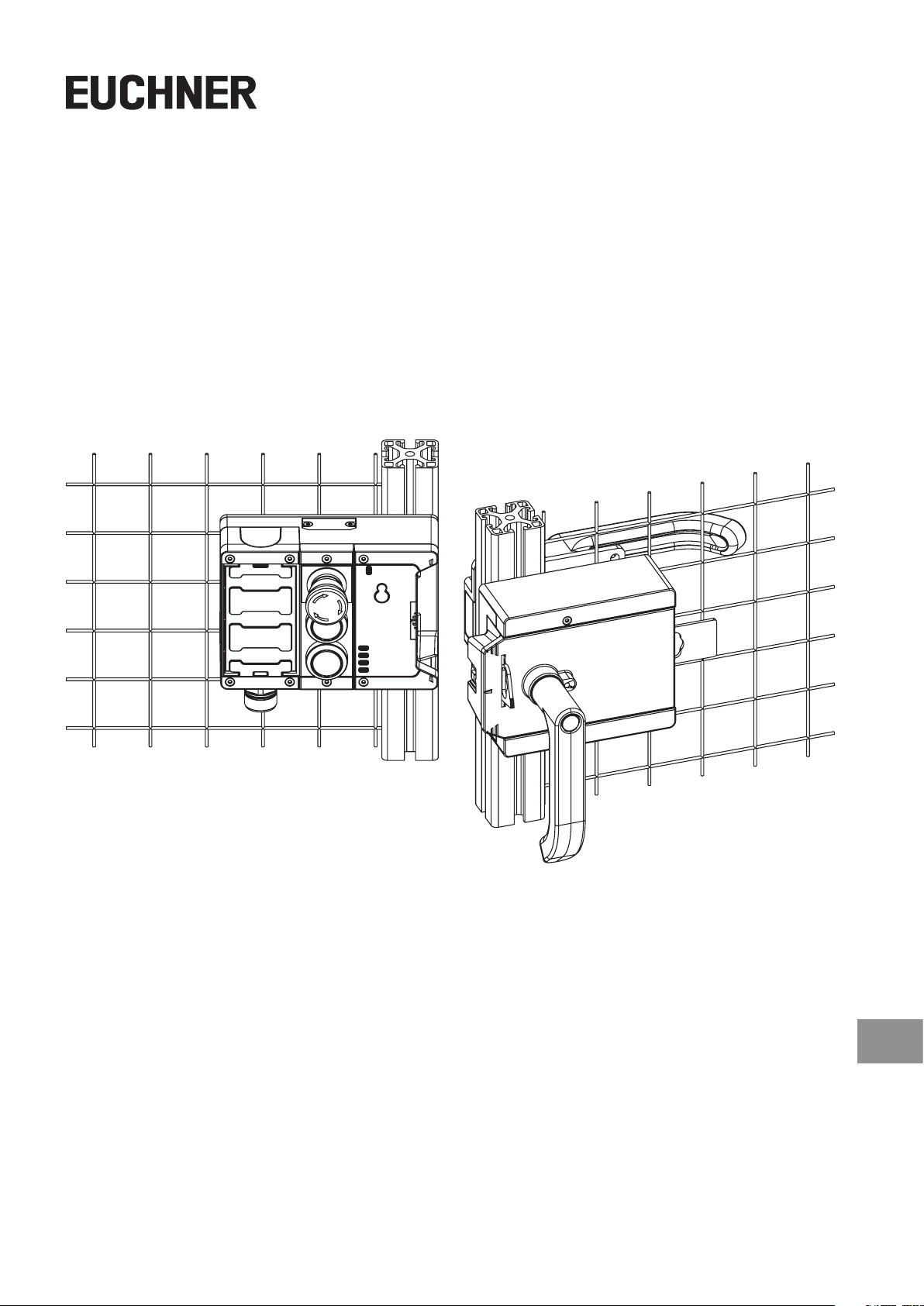
Operating Instructions
Safety Systems
MGB2-L1…-BR.-… / MGB2-L2…-BR.-…
MGB2-L1…-BP.-… / MGB2-L2…-BP.-…
from V1.0.0
EN
Page 2

Operating Instructions Safety Systems
MGB2-L1…-BR.-… / MGB2-L2…-BR.-… and MGB2-L1…-BP.-… / MGB2-L2…-BP.-…
Contents
1. About this document ............................................................................................. 5
1.1. Scope ............................................................................................................................................5
1.1.1. Notes on older product versions ......................................................................................5
1.2. Target group ..................................................................................................................................5
1.3. Key to symbols ...............................................................................................................................5
1.4. Supplementary documents ..............................................................................................................6
2. Correct use .......................................................................................................... 7
2.1. Main differences, MGB2-BP and MGB2-BR .........................................................................................8
3. Description of the safety function .......................................................................... 9
4. Exclusion of liability and warranty ....................................................................... 10
5. General safety precautions ................................................................................. 10
6. Function ............................................................................................................. 11
6.1. Locking module MGB2-L1/L2 ........................................................................................................11
6.2. Guard locking for version MGB2-L1 ................................................................................................12
6.3. Guard locking for version MGB2-L2 ................................................................................................12
7. System overview................................................................................................. 13
7.1. Locking module MGB2-L.-… ..........................................................................................................13
7.2. Handle module MGB2-H-….............................................................................................................13
7.3. Escape release MGB-E-... (optional) ................................................................................................14
7.4. Dimension drawing .......................................................................................................................15
8. Manual release ................................................................................................... 16
8.1. Auxiliary release and auxiliary key release (can be retrotted) ...........................................................16
8.1.1. Actuating auxiliary release .............................................................................................16
8.1.2. Actuating auxiliary key release .......................................................................................16
8.2. Emergency unlocking (can be retrotted) ........................................................................................17
8.2.1. Actuating emergency unlocking ......................................................................................17
8.3. Lockout mechanism ......................................................................................................................17
8.4. Escape release (optional) ..............................................................................................................18
8.4.1. Preparing escape release ..............................................................................................19
9. Mounting ............................................................................................................ 20
9.1. Replacing modules........................................................................................................................22
9.2. Mounting submodules ...................................................................................................................22
9.3. Replacing submodules ..................................................................................................................23
9.3.1. Replacing submodule with a submodule with a different function (changing conguration) ...23
9.3.2. Fitting and removing lenses and labels for controls and indicators ....................................24
9.4. Changing direction of connection ...................................................................................................24
2
(Translation of the original operating instructions) 2500233-01-05/19
Page 3

Operating Instructions Safety Systems
MGB2-L1…-BR.-… / MGB2-L2…-BR.-… and MGB2-L1…-BP.-… / MGB2-L2…-BP.-…
10. Changing the door hinge position ........................................................................ 25
10.1. Changing the interlocking/locking module to a different door hinge position ......................................25
10.2. Changing actuating direction of the handle module ..........................................................................25
11. Protection against environmental effects ............................................................. 27
12. Controls and indicators ....................................................................................... 27
13. Electrical connection .......................................................................................... 28
13.1. Using submodules ........................................................................................................................29
13.2. Notes about .........................................................................................................................29
13.3. Safety in case of faults ..................................................................................................................29
13.4. Fuse protection for power supply ...................................................................................................30
13.5. Requirements for connection cables ...............................................................................................30
13.6. Notes on cable laying ....................................................................................................................31
13.7. Changing device conguration (using DIP switches) .........................................................................32
13.7.1. Changing system family (BR/BP switching) ......................................................................32
13.7.2. Deactivating guard locking monitoring ............................................................................33
13.7.3. Activating release monitoring .........................................................................................33
13.8. Notes on operation with control systems ........................................................................................34
13.9. Connection of guard locking control ...............................................................................................35
13.9.1. Guard locking control for devices with IMM connection .....................................................35
13.9.2. Guard locking control for devices without IMM connection ................................................35
13.10. Terminal assignment and contact description .................................................................................. 36
13.11. Terminal assignment, submodule with plug connector M23 ..............................................................37
13.12. Operation as separate device ........................................................................................................38
13.13. Information on operation in a BR switch chain .................................................................................39
13.13.1. System times ...............................................................................................................39
13.13.2. Wiring a BR switch chain ................................................................................................39
13.13.3. Number of devices in switch chains ................................................................................39
13.13.4. Resetting in switch chains ..............................................................................................39
14. Setup ................................................................................................................. 40
14.1. Teach-in operation (only for MGB2 unicode) ..................................................................................... 40
14.2. Mechanical function test ................................................................................................................40
14.3. Electrical function test ...................................................................................................................40
15. System states ..................................................................................................... 42
15.1. Key to symbols .............................................................................................................................42
15.2. System status table MGB2-BR .......................................................................................................43
EN
15.3. System status table MGB2-BP........................................................................................................45
15.4. System status table (slot LED) .......................................................................................................47
16. Technical data .................................................................................................... 48
16.1. Radio frequency approvals.............................................................................................................49
16.2. Typical system times .....................................................................................................................50
2500233-01-05/19 (Translation of the original operating instructions)
3
Page 4

Operating Instructions Safety Systems
MGB2-L1…-BR.-… / MGB2-L2…-BR.-… and MGB2-L1…-BP.-… / MGB2-L2…-BP.-…
17. Troubleshooting and assistance ........................................................................... 51
17.1. Resetting errors ...........................................................................................................................51
17.2. Help on troubleshooting in the Internet ...........................................................................................51
17.3. Help on mounting in the Internet .....................................................................................................51
17.4. Application examples ....................................................................................................................51
18. Service .............................................................................................................. 51
19. Inspection and service ........................................................................................ 52
20. Declaration of conformity ................................................................................... 53
4
(Translation of the original operating instructions) 2500233-01-05/19
Page 5
Operating Instructions Safety Systems
DIP
MGB2-L1…-BR.-… / MGB2-L2…-BR.-… and MGB2-L1…-BP.-… / MGB2-L2…-BP.-…
1. About this document
1.1. Scope
These operating instructions are valid for all MGB2-L1…-BR.-… / MGB2-L2…-BR.-… and MGB2-L1…-BP.-… / MGB2-L2…-BP.-….
These operating instructions, the document “Safety information and maintenance” and any enclosed data sheet form the
complete user information for your device.
Series Guard locking types System families Product versions
L1 (guard locking by spring force)
MGB2
L2 (guard locking by solenoid force)
1.1.1. Notes on older product versions
Products with lower product versions or without a version number are not described by these operating instructions. Please
contact our support team in this case.
1.2. Target group
Design engineers and installation planners for safety systems on machines, as well as setup and servicing staff possessing
special expertise in handling safety components as well as expertise in the installation, setup, programming and diagnostics
of programmable logic controllers (PLC).
…-BP…
…-BR…
…-BP…
…-BR…
from V1.0.0
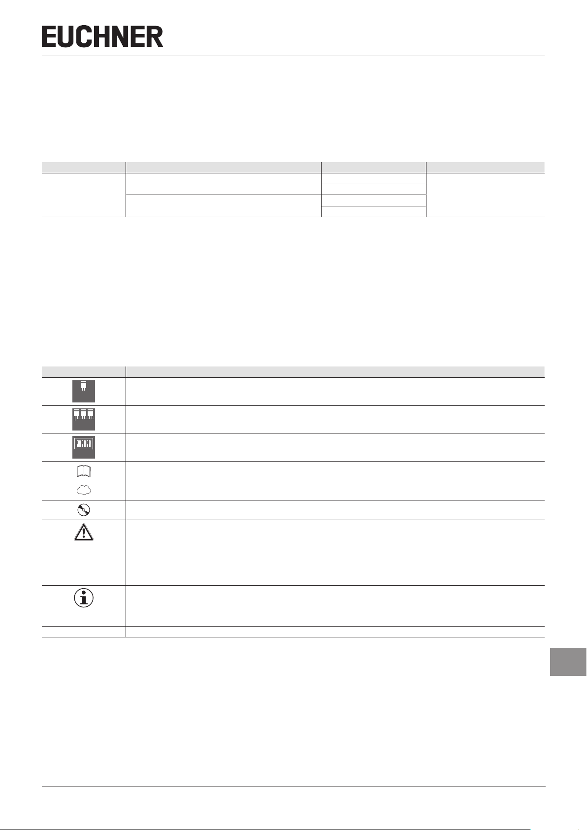
1.3. Key to symbols
Symbol/depiction Meaning
BP
BR
ON
OFF
www
DANGER
WARNING
CAUTION
NOTICE
Important!
Tip Useful information
This section applies on operation as MGB2-BP
This section applies on operation as MGB2-BR
In this section attention must be paid to the DIP switch settings
Printed document
Document is available for download at www.euchner.com
Document on CD
Safety precautions
Danger of death or severe injuries
Warning about possible injuries
Caution Slight injuries possible
Notice about possible device damage
Important information
2500233-01-05/19 (Translation of the original operating instructions)
EN
5
Page 6

Operating Instructions Safety Systems
MGB2-L1…-BR.-… / MGB2-L2…-BR.-… and MGB2-L1…-BP.-… / MGB2-L2…-BP.-…
1.4. Supplementary documents
The overall documentation for this device consists of the following documents:
Document title
(document number)
Safety Information and
Maintenance Safety System MGB2-BR/MGB2-BP
from V1.0.0
Operating Instructions
(2500233)
Possibly enclosed data
sheets
Contents
Basic information for safe setup and service
(this document)
Item-specic information about deviations or additions
www
Important!
Always read all documents to gain a complete overview of safe installation, setup and use of the
device. The documents can be downloaded from www.euchner.com. For this purpose enter the doc.
no. in the search box.
6
(Translation of the original operating instructions) 2500233-01-05/19
Page 7

Operating Instructions Safety Systems
DIP
MGB2-L1…-BR.-… / MGB2-L2…-BR.-… and MGB2-L1…-BP.-… / MGB2-L2…-BP.-…
2. Correct use
The system consists of at least one locking module MGB2-L1-…/MGB2-L2--… and one handle module MGB2-H…
The safety system MGB2-L.-… is an interlocking device with guard locking (type4). Devices with unicode evaluation possess
a high coding level, devices with multicode evaluation possess a low coding level.
The locking module can be congured with the aid of DIP switches. Depending on the setting, the locking module behaves
like a BP or BR device (see chapter 2.1. Main differences, MGB2-BP and MGB2-BR on page 8). In addition the guard
locking monitoring can be switched on or off. More detailed information about the possible settings is available in the chapter
13.7. Changing device conguration (using DIP switches) on page 32.
ON
With active guard locking monitoring the following applies:
OFF
In combination with a movable guard and the machine control, this safety component prevents the guard from being
opened while a dangerous machine function is being performed.
This means:
Ì Starting commands that cause a dangerous machine function must become active only when the guard is
closed and locked.
Ì The guard locking must not be unlocked until the dangerous machine function has ended.
Ì Closing and locking a guard must not cause automatic starting of a dangerous machine function. A separate
start command must be issued. For exceptions, refer to ENISO12100 or relevant C-standards.
With inactive guard locking monitoring the following applies:
In combination with a movable guard and the machine control, this safety component prevents dangerous machine
functions from occurring while the guard is open. A stop command is triggered if the guard is opened during the
dangerous machine function. With inactive guard locking monitoring, guard locking must be used only for process
protection.
This means:
Ì Starting commands that cause a dangerous machine function must become active only when the guard is
closed.
Ì Opening the guard triggers a stop command.
Ì Closing a guard must not cause automatic starting of a dangerous machine function. A separate start command
must be issued. For exceptions, refer to ENISO12100 or relevant C-standards.
Before the device is used, a risk assessment must be performed on the machine, e.g. in accordance with the following
standards:
Ì ENISO13849-1
Ì ENISO12100
Ì ENIEC62061
Correct use includes observing the relevant requirements for installation and operation, particularly based on the following
standards:
Ì ENISO13849-1
Ì ENISO14119
Ì ENIEC60204-1
The safety system MGB2 can be combined only with the intended modules in the MGB2 system family.
On the modication of system components, EUCHNER provides no warranty for function.
Locking modules with the conguration MGB2-BR can be integrated into a BR switch chain.
BR
Connection of several devices in a BR switch chain is permitted only using devices intended for series connection
in a BR switch chain. Check the operating instructions for the related device.
2500233-01-05/19 (Translation of the original operating instructions)
EN
7
Page 8

Operating Instructions Safety Systems
MGB2-L1…-BR.-… / MGB2-L2…-BR.-… and MGB2-L1…-BP.-… / MGB2-L2…-BP.-…
Important!
Ì The user is responsible for the proper integration of the device into a safe overall system. For this
purpose, the overall system must be validated, e.g. in accordance with ENISO13849-2.
Ì Correct use requires observing the permissible operating parameters (see chapter 16. Technical
data on page 48).
Ì If a data sheet is included with the product, the information on the data sheet applies.
Table 1: Possible combinations for MGB2 components
Handle module Submodules Submodules
Key to symbols
Evaluation unit
MGB2…BR/BP
from V1.0.0
Combination possible
– Combination not possible
MGB2-H-...
from V1.0.0
2.1. Main differences, MGB2-BP and MGB2-BR
System family Symbol Use
Optimized for operation in safe control systems.
MGB2-BP
MGB2-BR
If series connection is not necessary, the number of terminals required can be reduced using this system family.
BP
Linking of several guards on one shutdown path. As a consequence several safety doors can be very simply polled using one evaluation unit or two control system inputs.
BR
MSM-.-P-...
MSM-.-N-...
MSM-.-K-...
MSM-.-R-...
–
8
(Translation of the original operating instructions) 2500233-01-05/19
Page 9

MGB2-L1…-BR.-… / MGB2-L2…-BR.-… and MGB2-L1…-BP.-… / MGB2-L2…-BP.-…
DIP
DIP
3. Description of the safety function
Devices from this series feature the following safety functions:
With active guard locking monitoring the following applies:
ON
Monitoring of guard locking and the position of the guard
OFF
(interlocking device with guard locking according to ENISO14119)
Ì Safety function (see chapter 6. Function on page 11):
- The safety outputs are switched off when guard locking is released (monitoring of the locking element).
Important: This applies only if guard locking monitoring is active!
- The safety outputs are switched off when the guard is open.
- Guard locking can be activated only when the bolt tongue is located in the locking module (failsafe locking
mechanism).
Ì Safety characteristics: category, Performance Level, PFH
Activation of guard locking
Ì Safety function
If the device is used as guard locking for personnel protection, control of guard locking must be regarded as a
safety function.
The safety level of guard locking control is determined by the device PFH
PFH
of the standstill monitor).
D
ext.
Operating Instructions Safety Systems
(see chapter 16. Technical data on page 48).
D
and by the external control (e.g.
D
int.
Guardlocking Device
PFH
D
ext.
(e.g. standstill
monitor)
Ì Safety characteristics: category, Performance Level, PFH
With inactive guard locking monitoring the following applies:
ON
Monitoring of the guard position
OFF
(interlocking device according to ENISO14119)
Ì Safety function: The safety outputs are switched off when the guard is open (see chapter 6. Function on page
11).
Ì Safety characteristics: category, Performance Level, PFH
The following applies to devices with emergency stop:
Emergency stop
(emergency stop device according to ENISO13850)
(locking mean)
(see chapter 16. Technical data on page 48).
D
(see chapter 16. Technical data on page 48).
D
EN
Ì Safety function: Emergency stop function
Ì Safety characteristics: B
2500233-01-05/19 (Translation of the original operating instructions)
value (see chapter 16. Technical data on page 48)
10D
9
Page 10

Operating Instructions Safety Systems
MGB2-L1…-BR.-… / MGB2-L2…-BR.-… and MGB2-L1…-BP.-… / MGB2-L2…-BP.-…
4. Exclusion of liability and warranty
In case of failure to comply with the conditions for correct use stated above, or if the safety regulations are not followed,
or if any servicing is not performed as required, liability will be excluded and the warranty void.
5. General safety precautions
Safety switches fulll personnel protection functions. Incorrect installation or tampering can lead to fatal injuries to personnel.
Check the safe function of the guard and, if necessary, other safety functions particularly
Ì after any setup work
Ì each time after replacement of a component relevant to safety
Ì after an extended period without use
Ì after every fault
Ì after any change to the DIP switch settings
Independent of these checks, the safe function of the guard should be checked at suitable intervals as part of the maintenance schedule.
WARNING
Danger to life due to improper installation or due to bypassing (tampering). Safety components fulll
a personnel protection function.
Ì Safety components must not be bypassed, turned away, removed or otherwise rendered ineffec-
tive. On this topic pay attention in particular to the measures for reducing the possibility of bypassing according to ENISO14119:2013, section 7.
Ì The switching operation is allowed to be triggered only by the intended handle module MGB2-H…
that is positively fastened to the guard.
Ì Prevent bypassing by means of replacement actuators (only for multicode evaluation). For this
purpose, restrict access to actuators and to keys for releases, for example.
Ì Mounting, electrical connection and setup only by authorized personnel possessing the following
knowledge:
- specialist knowledge in handling safety components
- knowledge about the applicable EMC regulations
- knowledge about the applicable regulations on operational safety and accident prevention.
Important!
Prior to use, read the operating instructions and keep these in a safe place. Ensure the operating
instructions are always available during mounting, setup and servicing. For this reason you should
archive a printed copy of the operating instructions. You can download the operating instructions from
www.euchner.com.
10
(Translation of the original operating instructions) 2500233-01-05/19
Page 11

Operating Instructions Safety Systems
DIP
MGB2-L1…-BR.-… / MGB2-L2…-BR.-… and MGB2-L1…-BP.-… / MGB2-L2…-BP.-…
6. Function
6.1. Locking module MGB2-L1/L2
Together with a handle module, the locking module makes it possible to lock movable guards. The combination also serves
as a mechanical door stop at the same time.
ON
The following switch-on condition applies to the safety outputs FO1A and FO1B (also see chapters 15.2. System
OFF
status table MGB2-BR on page 43 and 15.3. System status table MGB2-BP on page 45):
DIP switch
Conguration
No fault in the device
Guard closed TRUE TRUE TRUE TRUE
Bolt tongue inserted in locking module TRUE TRUE TRUE TRUE
Guard locking active TRUE Not relevant TRUE Not relevant
In case of series connection:
Condition
Signal available from the upstream switch on the safety inputs FI1A
and FI1B
In case of separate operation:
DC24V present at the safety inputs FI1A and FI1B
Guard locking monitoring active inactive active inactive
System family MGB2-BR MGB2-BP
TRUE TRUE TRUE TRUE
&
TRUE TRUE Not relevant Not relevant
FO1A and FO1B are ON
The locking module detects the position of the guard and the position of the bolt tongue. The position of the guard locking
is also monitored.
Guard locking monitoring can be deactivated using DIP switches (see chapter 13.7. Changing device conguration (using
DIP switches) on page 32).
Important!
For use as guard locking for personnel protection in accordance with ENISO14119, guard locking
monitoring must be active.
The bolt tongue in the handle module is moved into and out of the locking module by actuating the door handle.
When the bolt tongue is fully inserted into the locking module, the locking arm locks the bolt tongue in this position. Depending
on the version, this locking is by spring force or solenoid force.
EN
2500233-01-05/19 (Translation of the original operating instructions)
11
Page 12

Operating Instructions Safety Systems
MGB2-L1…-BR.-… / MGB2-L2…-BR.-… and MGB2-L1…-BP.-… / MGB2-L2…-BP.-…
6.2. Guard locking for version MGB2-L1
(Guard locking actuated by spring force and released by power-ON)
Activating guard locking: close guard; no voltage at the solenoid.
Releasing guard locking: apply voltage to the solenoid.
The spring-operated guard locking functions in accordance with the closed-circuit current principle. If the voltage is interrupted
at the solenoid, the guard locking remains active and the guard cannot be opened directly.
Important!
If the guard is open when the power supply is interrupted and is then closed, guard locking is activated.
This can lead to persons being locked in unintentionally.
As long as the guard locking is closed, the bolt tongue cannot be pulled out of the locking module and the guard is locked.
If voltage is applied to the guard locking solenoid, the guard locking is opened and bolt tongue is released. The guard can
be opened.
6.3. Guard locking for version MGB2-L2
(Guard locking actuated by power-ON and released by spring force)
Important!
Use as guard locking for personnel protection is possible only in special cases, after strict assessment
of the accident risk (see ENISO14119:2013, section 5.7.1)!
Activating guard locking: apply voltage to the solenoid.
Releasing guard locking: disconnect voltage from the solenoid.
The magnetically actuated guard locking operates in accordance with the open-circuit current principle. If the voltage is
interrupted at the solenoid, the guard locking is released and the guard can be opened directly!
The guard can be opened as long as no voltage is applied to the guard locking solenoid.
If voltage is present at the guard locking solenoid, the guard locking is held in the locked position and the guard is locked.
12
(Translation of the original operating instructions) 2500233-01-05/19
Page 13

MGB2-L1…-BR.-… / MGB2-L2…-BR.-… and MGB2-L1…-BP.-… / MGB2-L2…-BP.-…
1 2
1
2
3
4
5
6
7. System overview
Figure 1: Overall system
7.1. Locking module MGB2-L.-…
3
Operating Instructions Safety Systems
Key:
1 Interlocking modul/Locking module (MGB2-I…/
MGB2-L…)
2 Escape release, optional (MGB-E-…)
3 Handle module (MGB2-H…)
Key:
1 Depending on version: Cable gland
M20x1,5 or plug connector
2 Module function LED indicators
3 Auxiliary release (optional, only on
version with guard locking)
LED indicator for submodule in
SLOT1
5 Submodule in SLOT1 (conguration
example)
6 Auxiliary marking for correct align-
ment in relation to the handle module
7 Locking arm
Terminals (X1-X4)
Internal reset
Notice:
Depending on the version, additional
controls and indicators may be integrated
into the cover and a mounting plate can
be included.
See enclosed data sheet.
Figure 2: Locking module MGB2-L.--…
7.2. Handle module MGB2-H-…
Figure 3: Handle module MGB2-H-…
2500233-01-05/19 (Translation of the original operating instructions)
Key:
1 Door handle
2 Hinged lockout mechanism
3 Automatically extending lockout mechanism (optional)
Auxiliary markings for max. permissible mounting distance
5 Bolt tongue
6 Latching pin for handle adjustment
EN
13
Page 14

Operating Instructions Safety Systems
MGB2-L1…-BR.-… / MGB2-L2…-BR.-… and MGB2-L1…-BP.-… / MGB2-L2…-BP.-…
7.3. Escape release MGB-E-... (optional)
Key:
1 2 3 4
Figure 4: Escape release MGB-E-...
1 Door handle
2 Housing
3 Actuation axis 8 x 8 mm
(different lengths available)
Protective sleeve
Notice:
Depending on the version, a mounting plate can be included.
See enclosed data sheet.
14
(Translation of the original operating instructions) 2500233-01-05/19
Page 15

Operating Instructions Safety Systems
15
40
52,5
(289)
MGB2-L1…-BR.-… / MGB2-L2…-BR.-… and MGB2-L1…-BP.-… / MGB2-L2…-BP.-…
40
40
114
7.4. Dimension drawing
4
130
155
114,2 110,59
62,3 22,2
115,5
63
42
130
4
155
EN
Figure 5: Dimension drawing MGB2 tted, without optional mounting plates
2500233-01-05/19 (Translation of the original operating instructions)
15
Page 16

Operating Instructions Safety Systems
DIP
MGB2-L1…-BR.-… / MGB2-L2…-BR.-… and MGB2-L1…-BP.-… / MGB2-L2…-BP.-…
8. Manual release
Some situations require the guard locking to be released manually (e.g. malfunctions or an emergency). A function test
should be performed after release.
More information on this topic can be found in the standard ENISO14119:2013, section 5.7.5.1. The device can feature
the following release functions:
8.1. Auxiliary release and auxiliary key release (can be retrotted)
In the event of malfunctions, the guard locking can be released with the auxiliary release irrespective of the state of the
solenoid.
The safety outputs are switched off when the auxiliary release is actuated. Use the safety outputs to generate a stop
command.
The monitoring output OL is switched off; OD indicates the current state of the guard. Open the guard and close it again
after resetting the auxiliary release. The device will then operate normally again.
8.1.1. Actuating auxiliary release
1. Remove seal label or make a hole.
2. Undo locking screw.
3. Using a screwdriver, turn the auxiliary release to in the direction of the arrow.
¨ Guard locking is released.
ON
OFF
Ì When release monitoring is active, the system enters into a latching fault when the auxiliary release is actuated.
See System status table, signal sequence incorrect status (DIA red, Lock ashes 1 time).
Ì The system might not enter into a latching fault if the auxiliary release is actuated very slowly.
Important!
Ì The auxiliary release must be reset at the control system level, e.g. by means of a plausibility
check (status of the safety outputs does not match the guard locking activation signal). See
ENISO14119:2013, sec. 5.7.5.4.
Ì The auxiliary release is not a safety function.
Ì The machine manufacturer must select and use a suitable release (escape release, emergency
unlocking, etc.) for a specic application. A hazard assessment is required for this purpose. It may
be necessary to take specications from a product standard into account.
Ì The correct function must be checked at regular intervals.
Ì Loss of the release function due to mounting errors or damage during mounting. Check the re-
lease function every time after mounting.
Ì Please observe the notes on any enclosed data sheets.
8.1.2. Actuating auxiliary key release
On devices with auxiliary key release (can be retrotted), simply turn the key to release. Function as for auxiliary release.
For mounting, see the auxiliary key release supplement.
1 2
Figure 6: Auxiliary release
16
3
(Translation of the original operating instructions) 2500233-01-05/19
Page 17

Operating Instructions Safety Systems
MGB2-L1…-BR.-… / MGB2-L2…-BR.-… and MGB2-L1…-BP.-… / MGB2-L2…-BP.-…
8.2. Emergency unlocking (can be retrotted)
Permits opening of a locked guard from outside the danger zone without tools. For mounting, see the mounting supplement.
Important!
Ì It must be possible to operate the emergency unlocking manually from outside the protected area
without tools.
Ì The emergency unlocking must possess a marking indicating that it may be used only in an emer-
gency.
Ì The actuator must not be under tensile stress during manual release.
Ì The unlocking function meets all other requirements from ENISO14119.
Ì The emergency unlocking meets the requirements of Category B according to
ENISO13849-1:2015.
Ì Loss of the release function due to mounting errors or damage during mounting.
Ì Check the release function every time after mounting.
Ì Please observe the notes on any enclosed data sheets.
8.2.1. Actuating emergency unlocking
Ì Turn emergency unlocking clockwise until it clicks into place.
¨ Guard locking is released.
To reset, press the snap-in bolt inward using a small screwdriver or similar tool and turn the emergency unlocking back.
The safety outputs are switched off when the emergency unlocking is actuated. Use the safety outputs to generate
a stop command.
The monitoring output OL is switched off; OD indicates the current state of the guard. Open the guard and close it again
after resetting the emergency unlocking. The device will then operate normally again.
8.3. Lockout mechanism
If the lockout mechanism is pivoted out, the bolt tongue cannot be extended. The lockout mechanism can be secured with
padlocks (see Figure 7). This is intended to prevent people from being locked in unintentionally. The lockout mechanism
does not fulll any safety function.
¨ To pivot out, press the grooved part (possible only with bolt tongue retracted).
Key:
1
Hinged lockout mechanism
Padlock ∅min. 2mm, ∅max. 10 mm
2
Automatically extending lockout mechanism (optional)
1
Padlock ∅min. 6mm, ∅max. 10 mm
2
Notice:
You can t a maximum of 3 locks ∅8mm per lockout mechanism.
Figure 7: Lockout mechanism secured with padlock
2500233-01-05/19 (Translation of the original operating instructions)
EN
17
Page 18

Operating Instructions Safety Systems
DIP
MGB2-L1…-BR.-… / MGB2-L2…-BR.-… and MGB2-L1…-BP.-… / MGB2-L2…-BP.-…
8.4. Escape release (optional)
The escape release is used to open a locked guard from the inside without tools.
ON
When release monitoring is active, the system enters into a latching fault when the escape release is actuated.
OFF
See System status table, signal sequence incorrect status (DIA red, Lock ashes 1 time).
The system might not enter into a latching fault if the escape release is actuated very slowly.
Depending on the parameters set in your conguration environment, the system may enter into a latching fault if the escape
release is actuated (see chapter 17. Troubleshooting and assistance on page 51).
Important!
Ì It must be possible to actuate the escape release manually from inside the protected area without
tools.
Ì It must not be possible to reach the escape release from the outside.
Ì The bolt tongue must not be under tensile stress during manual release.
Ì The escape release meets the requirements of Category B according to ENISO13849-1:2015.
Ì The correct function must be checked at regular intervals.
Ì Please observe the notes on any enclosed data sheets.
Ì Fit escape release such that operation, inspection and maintenance are possible.
Ì The actuation axis for the escape release must be inserted min. 9 mm into the handle module. Note the information on
the different prole widths in the chapter 8.4.1. Preparing escape release on page 19.
Ì Align escape release axis at right angles to the handle module. See Figure 9.
18
(Translation of the original operating instructions) 2500233-01-05/19
Page 19

MGB2-L1…-BR.-… / MGB2-L2…-BR.-… and MGB2-L1…-BP.-… / MGB2-L2…-BP.-…
D + 10,25
8.4.1. Preparing escape release
Operating Instructions Safety Systems
Prole width Length required for
D D+9 D+17
30 mm 39 mm 47 mm Standard escape release
40 mm 49 mm 57 mm Standard escape release
45 mm 54 mm 62 mm Standard escape release
50 mm 59 mm 67 mm Standard escape release
Actuation axis
Without
mounting
plates
With mounting
plates
(4 mm each)
Example without mounting plates:
Which EUCHNER parts are required? Necessary work steps
with 107 mm axis
(order no. 100465)
with 107 mm axis
(order no. 100465)
If necessary,
extended actuation axis (order no. 106761)
with 107 mm axis
(order no. 100465)
and
extended actuation axis (order no. 106761)
with 107 mm axis
(order no. 100465)
and
extended actuation axis (order no. 106761)
Shorten to required length
Without mounting plates:
None
With mounting plates:
Use extended actuation axis and protective sleeve and
shorten to required length
Use extended actuation axis and protective sleeve and
shorten to required length
Use extended actuation axis and protective sleeve and
shorten to required length
Actuation axis Protective sleeve
M4
Escape release
250
D
Handle module
(11,5) 55,5
A
1
4
2
3
1
Insert actuation axis. The snap ring A must be in contact with the escape release B.
2
Fit door handle.
3
Tighten xing screw to 2Nm and press in cap.
Fit protective sleeve.
55,5
182
(+4 mm per mounting plate)
±1,25
D -1
(+4 mm per mounting plate)
B
EN
Figure 8: Preparing escape release
2500233-01-05/19 (Translation of the original operating instructions)
19
Page 20

Operating Instructions Safety Systems
MGB2-L1…-BR.-… / MGB2-L2…-BR.-… and MGB2-L1…-BP.-… / MGB2-L2…-BP.-…
9. Mounting
WARNING
Mounting must be performed only by authorized personnel.
With two-leaf hinged doors, one of the two door leaves must also be latched mechanically.
Use a rod latch (Item) or a double-door lock (Bosch Rexroth) for this purpose, for example.
Important!
Ì If installed ush, the switching distance changes as a function of the installation depth and the
guard material.
Operating distance
Locking
module
Flush installation
Operating distance
Locking
module
Surface mounting
Tip!
Handle module
Handle module
Ì You will nd an animation on the mounting process at www.euchner.com.
Ì The pushbuttons and indicators can be customized using replaceable color covers and labels.
For mounting steps , see Figure 9 and Figure 12 to Figure 17.
Attach system such that operation of the auxiliary release as well as inspection and maintenance are possible.
The locking screw must be screwed back in and sealed after assembly and after every use of the auxiliary release. (Seal
labels order no. 155853). Tightening torque 0.5Nm.
20
(Translation of the original operating instructions) 2500233-01-05/19
Page 21

M6
T10
Operating Instructions Safety Systems
MGB2-L1…-BR.-… / MGB2-L2…-BR.-… and MGB2-L1…-BP.-… / MGB2-L2…-BP.-…
Figure 9: Installation example for door hinged on the right (general view)
EN
2500233-01-05/19 (Translation of the original operating instructions)
21
 Loading...