

EUCHNER MGB2-Ixx-MLI series, MGB2-I series, MGB2-H series, MGB-E series, MGB2-L1 Operating Instructions Manual
...Page 1

EN
Operating Instructions
Interlocking/Locking Modules
MGB2-I..-MLI-... / MGB2-L..-MLI-... (Modular)
from V1.00.0
Page 2

Operating Instructions Interlocking/Locking Modules
MGB2-I..-MLI-... / MGB2-L..-MLI-... (Modular)
2
(Translation of the original operating instructions) 2500234-01-08/18
Contents
1. About this document ............................................................................................. 4
1.1. Scope ............................................................................................................................................4
1.1.1. Notes on older product versions ......................................................................................4
1.2. Target group ..................................................................................................................................4
1.3. Key to symbols ...............................................................................................................................4
1.4. Supplementary documents ..............................................................................................................4
2. Correct use .......................................................................................................... 5
3. Description of the safety function .......................................................................... 7
4. Exclusion of liability and warranty ......................................................................... 9
5. General safety precautions ................................................................................... 9
6. Function ............................................................................................................. 10
6.1. Interlocking module MGB2-I... (or a correspondingly congured MGB2-L2) .........................................10
6.2. Locking module MGB2-L... .............................................................................................................10
6.2.1. Guard locking for version MGB2-L1 ................................................................................10
6.2.2. Guard locking for version MGB2-L2 ................................................................................10
6.3. Control of guard locking MGB2-L1 and MGB2-L2 .............................................................................11
7. System overview................................................................................................. 12
7.1. Interlocking/locking module MGB2-I../MGB2-L.. ...............................................................................12
7.2. Handle module MGB2-H-….............................................................................................................13
7.3. Escape release MGB-E-... (optional) ................................................................................................13
7.4. Dimension drawings ......................................................................................................................14
7.4.1. Interlocking/locking module MGB2-I.../MGB2-L... .............................................................14
7.4.2. Handle module MGB2-H... ..............................................................................................14
7.4.3. Escape release MGB-E-... ..............................................................................................15
7.4.4. Assembly of MGB2-L, MGB2-H and MGB-E (example on prole 40x40) ...............................16
7.4.5. Drilling pattern, complete system with bus module MBM and
optional extension module MCM .....................................................................................17
7.4.6. Drilling pattern escape release MGB-E ............................................................................18
8. Manual release ................................................................................................... 19
8.1. Auxiliary release............................................................................................................................19
8.2. Lockout mechanism ......................................................................................................................20
8.3. Escape release (optional) ..............................................................................................................20
8.3.1. Preparing escape release ..............................................................................................21
9. Mounting ............................................................................................................ 22
9.1. Replacing modules........................................................................................................................23
9.2. Mounting submodules ...................................................................................................................23
9.3. Replacing submodules ..................................................................................................................24
9.3.1. Replacing faulty submodules ..........................................................................................24
9.3.2. Replacing submodule with a submodule with a different function (changing conguration) ...24
9.3.3. Fitting and removing lenses and labels for controls and indicators ....................................25
Page 3

3
2500234-01-08/18 (Translation of the original operating instructions)
Operating Instructions Interlocking/Locking Modules
MGB2-I..-MLI-... / MGB2-L..-MLI-... (Modular)
EN
10. Changing the door hinge position ........................................................................ 26
10.1. Changing the interlocking/locking module to a different door hinge position ......................................26
10.2. Changing actuating direction of the handle module ..........................................................................26
11. Protection against environmental effects ............................................................. 28
12. Controls and indicators ....................................................................................... 28
13. Electrical connection .......................................................................................... 29
13.1. Connecting modules .....................................................................................................................29
13.2. Using submodules ........................................................................................................................30
14. Data blocks for interlocking/locking module MGB2-I or MGB2-L .......................... 31
15. Setup ................................................................................................................. 31
15.1. Teach-in operation (only for MGB2 unicode) .....................................................................................31
15.2. Mechanical function test ................................................................................................................32
15.3. Electrical function test ...................................................................................................................32
15.4. Replacing a module .....................................................................................................................32
16. System status table, module LEDs ....................................................................... 33
16.1. System indications if there are faults (module LEDs) ........................................................................33
16.2. System indications during setup, teach-in and normal operation .......................................................34
17. System status table (slot LEDs) ........................................................................... 35
18. Technical data .................................................................................................... 36
18.1. Radio frequency approvals.............................................................................................................37
19. Troubleshooting and assistance ........................................................................... 38
19.1. Resetting general faults .................................................................................................................38
19.2. Fault on actuating the escape release ............................................................................................38
19.3. Resetting system to factory settings ..............................................................................................38
20. Service .............................................................................................................. 39
21. Inspection and service ........................................................................................ 39
22. Declaration of conformity ................................................................................... 40
Page 4
Operating Instructions Interlocking/Locking Modules
MGB2-I..-MLI-... / MGB2-L..-MLI-... (Modular)
4
(Translation of the original operating instructions) 2500234-01-08/18
1. About this document
1.1. Scope
These operating instructions are valid for all Interlocking/Locking Modules MGB2-I..-MLI-... / MGB2-L..-MLI-... (Modular). These
operating instructions, the document “Safety information and maintenance”, the operating instructions for the bus module
MBM and any enclosed data sheet form the complete user information for your device.
Series Guard locking types System families Product versions
MGB2
I (without guard locking)
…-MLI-…
(operation on a bus module MBM)
from V1.00.0
L1 (guard locking by spring force) from V1.00.0
L2 (guard locking by solenoid force) from V1.00.0
1.1.1. Notes on older product versions
Products with lower product versions or without a version number are not described by these operating instructions. Please
contact our support team in this case.
1.2. Target group
Design engineers and installation planners for safety devices on machines, as well as setup and servicing staff possessing
special expertise in handling safety components as well as expertise in the installation, setup, programming and diagnostics
of programmable logic controllers (PLC) and bus systems.
1.3. Key to symbols
Symbol/depiction Meaning
Printed document
www
Document is available for download at www.euchner.com
Document on CD
DANGER
WARNING
CAUTION
Safety precautions
Danger of death or severe injuries
Warning about possible injuries
Caution Slight injuries possible
NOTICE
Important!
Notice about possible device damage
Important information
Tip Useful information
1.4. Supplementary documents
The overall documentation for this device consists of the following documents:
Document title
(document number)
Contents
Operating Instructions
Interlocking/Locking
Modules MGB2-L..-MLI
(2500234)
(this document)
www
Safety Information and
Maintenance
(2500232)
Information sheet with important safety information
Operating Instructions Bus
Modules MBM-..-MLI
(2500235)
Conguration manual for the connection to the bus and data evaluation in MLI systems
www
Possibly enclosed data
sheets
Article-specic information with deviations or additions to the operating instructions as well as data sheets for submodules
Page 5

5
2500234-01-08/18 (Translation of the original operating instructions)
Operating Instructions Interlocking/Locking Modules
MGB2-I..-MLI-... / MGB2-L..-MLI-... (Modular)
EN
Important!
Always read all documents to gain a complete overview of safe installation, setup and use of the
device. The documents can be downloaded from www.euchner.com. For this purpose enter the doc.
no. in the search box.
2. Correct use
The modular devices described here can only be operated with a suitable bus module MBM-...-MLI-....
For the MGB2-I... the following applies:
Along with the bus module MBM, the system consists of at least one interlocking module MGB2-I... and one handle module
MGB2-H…
The safety system MGB2-I... is an interlocking device without guard locking (type4). Devices with unicode evaluation possess
a high coding level, devices with multicode evaluation possess a low coding level.
In combination with a movable guard and the machine control, this safety component prevents dangerous machine functions
from occurring while the guard is open. A stop command is triggered if the guard is opened during the dangerous machine
function.
This means:
Ì Starting commands that cause a dangerous machine function must become active only when the guard is closed.
Ì Opening the guard triggers a stop command.
Ì Closing a guard must not cause automatic starting of a dangerous machine function. A separate start command must
be issued. For exceptions, refer to ENISO12100 or relevant C-standards.
For the MGB2-L... the following applies:
Along with the bus module MBM, the system consists of at least one locking module MGB2-L... and one handle module
MGB2-H…
The safety system MGB2-L... is an interlocking device with guard locking (type4). Devices with unicode evaluation possess
a high coding level, devices with multicode evaluation possess a low coding level.
In combination with a movable guard and the machine control, this safety component prevents the guard from being opened
while a dangerous machine function is being performed.
This means:
Ì The unlocking of the guard locking by the control system triggers a stop command.
Ì Starting commands that cause a dangerous machine function must become active only when the guard is closed and
locked.
Ì The guard locking device must not be unlocked until the dangerous machine function has ended.
Ì Closing and locking a guard must not cause automatic starting of a dangerous machine function. A separate start com-
mand must be issued. For exceptions, refer to ENISO12100 or relevant C-standards.
For MGB2-I.. /MGB2-L..
Before the device is used, a risk assessment must be performed on the machine, e.g. in accordance with the following
standards:
Ì ENISO13849-1, Safety of machinery – Safety-related parts of control systems – Part 1: General principles for design
Ì ENISO12100, Safety of machinery – General principles for design – Risk assessment and risk reduction
Ì ENIEC62061, Safety of machinery – Functional safety of safety-related electrical, electronic and programmable elec-
tronic control systems.
Page 6
Operating Instructions Interlocking/Locking Modules
MGB2-I..-MLI-... / MGB2-L..-MLI-... (Modular)
6
(Translation of the original operating instructions) 2500234-01-08/18
Correct use includes observing the relevant requirements for installation and operation, particularly based on the following
standards:
Ì ENISO13849-1, Safety of machinery – Safety-related parts of control systems – Part 1: General principles for design
Ì ENISO14119, Safety of machinery – Interlocking devices associated with guards – Principles for design and selection
Ì ENIEC60204-1, Safety of machinery – Electrical equipment of machines – Part 1: General requirements.
Ì ENIEC62061, Safety of machinery – Functional safety of safety-related electrical, electronic and programmable elec-
tronic control systems.
The safety system MGB2-.-MLI... is only allowed to be combined with suitable MLI modules (see Table 1: Combination options
for modules with MLI technology).
On the modication of system components, EUCHNER provides no warranty for function.
The customer is responsible for the safe overall function, especially for the safe integration into an overall system.
Important!
Ì The user is responsible for the proper integration of the device into a safe overall system. For this
purpose, the overall system must be validated, e.g. in accordance with ENISO13849-2.
Ì Correct use requires observing the permissible operating parameters (see chapter 18. Technical
data on page 36).
Ì If a data sheet is included with the product, the information on the data sheet applies.
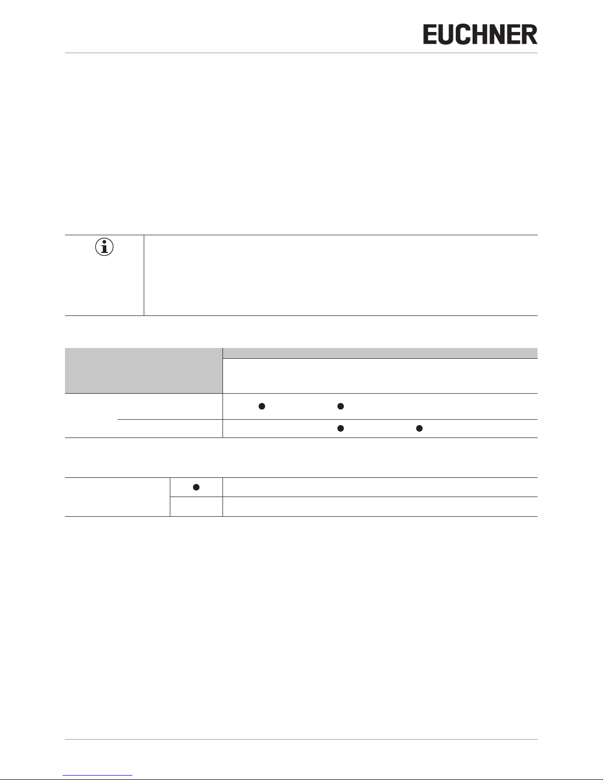
Table 1: Combination options for modules with MLI technology
Bus module Base units
Handle module Submodules Submodules Submodules
MGB2-H-...
from V1.00.0
MSM-.-P-...
MSM-.-R-...
MSM-.-N-...
MSM-.-E-...
MSM-.-K-...
MBM-...-MLI
from V1.00.0
Interlocking/locking module
MGB2-I..-MLI/MGB2-L..-MLI
from V1.00.0
- -
Extension module
MCM-...-MLI
- -
Key to symbols
Combination possible
- Combination not possible
Page 7

7
2500234-01-08/18 (Translation of the original operating instructions)
Operating Instructions Interlocking/Locking Modules
MGB2-I..-MLI-... / MGB2-L..-MLI-... (Modular)
EN
3. Description of the safety function
Important!
You will nd detailed instructions on the determination of reliability values in the operating instructions
for your bus module.
Devices from this series feature the following safety functions:
For the MGB2-L... the following applies:
Monitoring of guard locking and the position of the guard
(interlocking device with guard locking according to ENISO14119)
Ì Safety function (see chapter 6. Function on page 10):
- If the guard locking is unlocked, safety bit LM.I_UK (ÜK)=0 (monitoring of the locking element).
- If the guard is open, safety bit LM.I_SK (SK)=0 (monitoring of the position of the guard).
- Guard locking can be activated only when the bolt tongue is located in the locking module (failsafe locking mechanism).
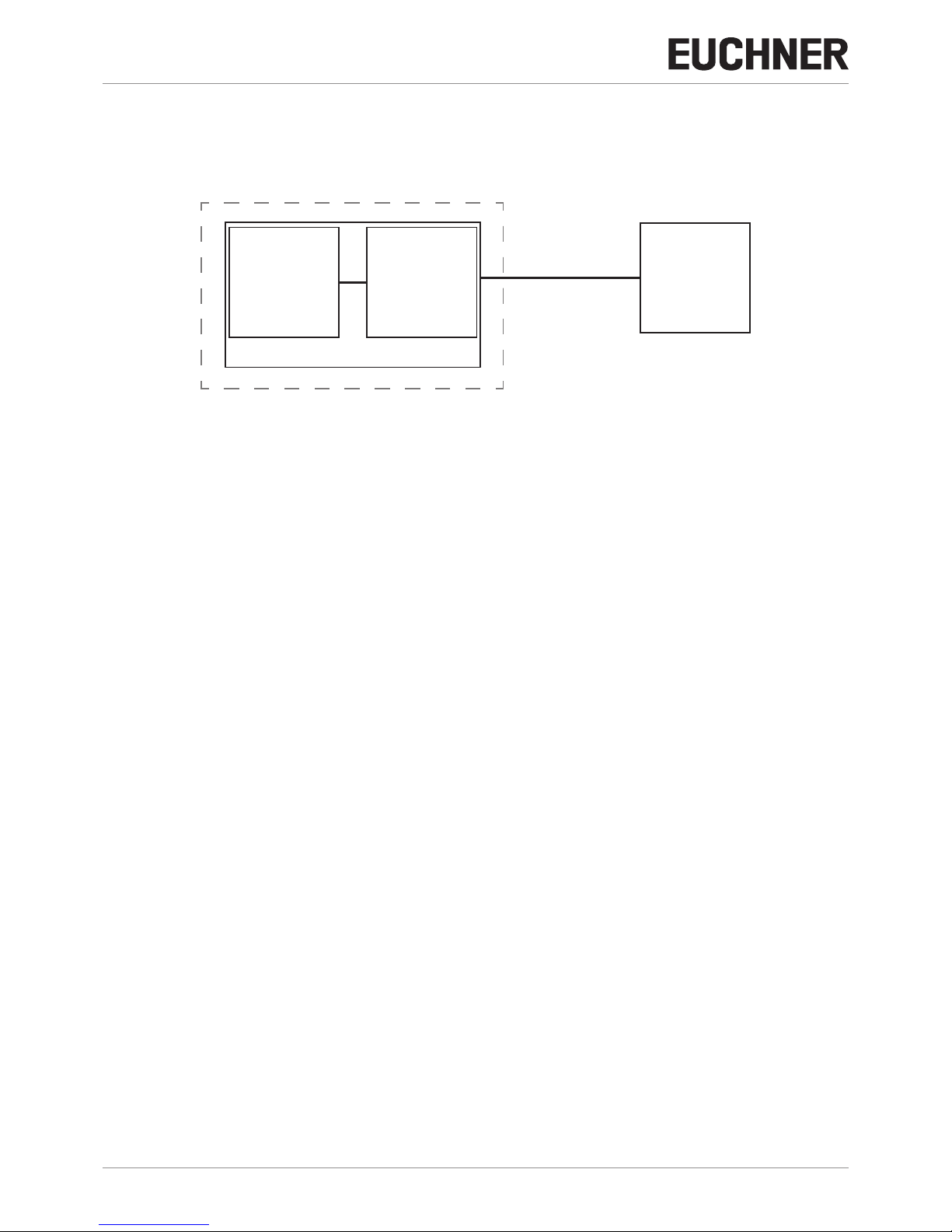
PLC
PFH
D, Sys
PFH
D, MBM
PFH
D, MGB2-L
Guardlocking
Device
MGB2-L...
Busmodule
MBM
EUCHNER ModuleLink-System (MLI)
Safetybit LM.FI_UK_
(Guardlock monitoring)
Ì Safety characteristics:
Category, Performance Level, PFHD
(reliability values according to EN13849-1 see 18. Technical data).
Control of guard locking (safety bit FO_CL)
Ì Safety function:
If the device is used as guard locking for personnel protection, control of guard locking must be regarded as a safety
function.
The safety level of guard locking control is determined by the system PFH
D
sys.
and by the external control (e.g. safe
PLC).
PFH
D, ext.
PFHD
, Sys
Guardlocking
Device
MGB2-L...
Busmodule
MBM
EUCHNER ModuleLink-System (MLI)
(e.g. standstill
monitor)
Safetybit FO_CL
(Guardlocking)
PFH
D, MBM
PFH
D, MGB2-L
Ì Safety characteristics of the bus module MBM and the locking module MGB2-L:
Category, Performance Level, PFHD
(reliability values according to EN13849-1 see 18. Technical data).
For MGB2-I... (or a correspondingly congured MGB2-L...) the following applies:
Page 8
Operating Instructions Interlocking/Locking Modules
MGB2-I..-MLI-... / MGB2-L..-MLI-... (Modular)
8
(Translation of the original operating instructions) 2500234-01-08/18
Monitoring of the guard position
(interlocking device according to ENISO14119)
Ì Safety function: If the guard is open the safety bit LM.I_SK (SK)=0. (See chapter 6. Function on page 10).
PLC
PFH
D, Sys
PFH
D, MBM
PFH
D, MGB2-I
Interlocking
Device
MGB2-L...
Busmodule
MBM
EUCHNER ModuleLink-System (MLI)
Safetybit LM.FI_SK_
(Interlock monitoring)
Ì Safety characteristics:
Category, Performance Level, PFHD
(reliability values according to EN13849-1 see 18. Technical data).
Page 9

9
2500234-01-08/18 (Translation of the original operating instructions)
Operating Instructions Interlocking/Locking Modules
MGB2-I..-MLI-... / MGB2-L..-MLI-... (Modular)
EN
4. Exclusion of liability and warranty
In case of failure to comply with the conditions for correct use stated above, or if the safety instructions are not followed,
or if any servicing is not performed as required, liability will be excluded and the warranty void.
5. General safety precautions
Safety switches fulll personnel protection functions. Incorrect installation or tampering can lead to fatal injuries to personnel.
Check the safe function of the guard and, if necessary, other safety functions particularly
Ì after any setup work
Ì each time after replacement of a component relevant to safety
Ì after an extended period without use
Ì after every fault
Ì after any change to the DIP switch settings
Independent of these checks, the safe function of the guard should be checked at suitable intervals as part of the maintenance schedule.
WARNING
Danger to life due to improper installation or due to bypassing (tampering). Safety components perform
a personnel protection function.
Ì Safety components must not be bypassed, turned away, removed or otherwise rendered ineffec-
tive. On this topic pay attention in particular to the measures for reducing the possibility of bypassing according to ENISO14119:2013, section 7.
Ì The switching operation is allowed to be triggered only by the intended handle module MGB2-H…
that is positively fastened to the guard.
Ì Prevent bypassing by means of replacement actuators (only for multicode evaluation). For this
purpose, restrict access to actuators and to keys for releases, for example.
Ì Mounting, electrical connection and setup only by authorized personnel possessing the following
knowledge:
- specialist knowledge in handling safety components
- knowledge about the applicable EMC regulations
- knowledge about the applicable regulations on occupational safety and accident prevention.
Important!
Prior to use, read the operating instructions and keep these in a safe place. Ensure the operating
instructions are always available during mounting, setup and servicing. For this reason you should
archive a printed copy of the operating instructions. You can download the operating instructions from
www.euchner.com.
Page 10
Operating Instructions Interlocking/Locking Modules
MGB2-I..-MLI-... / MGB2-L..-MLI-... (Modular)
10
(Translation of the original operating instructions) 2500234-01-08/18
6. Function
6.1. Interlocking module MGB2-I... (or a correspondingly congured MGB2-L2)
Together with a handle module, the interlocking module makes it possible to interlock movable guards. The combination
also serves as a mechanical door stop at the same time.
The following switch-on conditions apply to safety bit LM.FI_SK (SK):
Ì Guard closed
Ì Bolt tongue inserted in the interlocking module
See also chapter 16.2. System indications during setup, teach-in and normal operation on page 34 and the operating
instructions for bus module MBM.
The interlocking module detects the position of the guard and the position of the bolt tongue. The bolt tongue in the handle
module is moved into and out of the interlocking module by actuating the door handle.
6.2. Locking module MGB2-L...
Together with a handle module, the locking module makes it possible to lock movable guards. The combination also serves
as a mechanical door stop at the same time. There are various congurations for the control of the guard locking (see
section 6.3. Control of guard locking MGB2-L1 and MGB2-L2). The following descriptions in 6.2.1 and 6.2.2 describe the
function of the guard locking with the factory setting.
Important!
To operate the device as guard locking for personnel protection according to ENISO14119, the safety
bit LM.FI_UK (ÜK) must be evaluated.
The following switch-on conditions apply to the safety bit LM.FI_UK (ÜK):
Ì Guard closed
Ì Bolt tongue inserted in the locking module
Ì Guard locking in locking position (guard locking monitoring)
See also chapter 16.2. System indications during setup, teach-in and normal operation on page 34 and the operating
instructions for bus module MBM.
The locking module detects the position of the guard and the position of the bolt tongue. The position of the guard locking
is also monitored. The bolt tongue in the handle module is moved into and out of the locking module by actuating the door
handle.
If the bolt tongue is fully inserted into the locking module, the guard locking can lock the bolt tongue in this position. Depending on the version, this locking is by spring force or solenoid force.
6.2.1. Guard locking for version MGB2-L1
(Guard locking actuated by spring force and released by power-ON)
Guard locking: Close guard; no voltage at the solenoid
(with factory setting: safety bit LM.FO_CL =0.)
Releasing guard locking: Apply voltage to the solenoid (with factory setting: safety bit LM.FO_CL =1.).
The spring-operated guard locking functions in accordance with the closed-circuit current principle. If the voltage is interrupted
at the solenoid, the guard locking remains active and the guard cannot be opened directly.
Important!
If the guard is open when the power supply is interrupted and is then closed, guard locking is activated.
This can lead to persons being locked in unintentionally.
As long as the guard locking is closed, the bolt tongue cannot be pulled out of the locking module and the guard is locked.
If voltage is applied to the guard locking solenoid, the guard locking is opened and bolt tongue is released. The guard can
be opened.
6.2.2. Guard locking for version MGB2-L2
(Guard locking actuated by power-ON and released by spring force)
Page 11

11
2500234-01-08/18 (Translation of the original operating instructions)
Operating Instructions Interlocking/Locking Modules
MGB2-I..-MLI-... / MGB2-L..-MLI-... (Modular)
EN
Important!
Use as guard locking for personnel protection is possible only in special cases, after strict assessment
of the accident risk (see ENISO14119:2013, section 5.7.1)!
Guard locking: Apply voltage to the solenoid (with factory setting: safety bit LM.FO_CL =0.).
Releasing guard locking: Disconnect voltage from the solenoid (with factory setting: safety bit LM.FO_CL =1.).
The magnetically actuated guard locking operates in accordance with the open-circuit current principle. If the voltage is
interrupted at the solenoid, the guard locking is released and the guard can be opened directly!
The guard can be opened as long as no voltage is applied to the guard locking solenoid.
If voltage is present at the guard locking solenoid, the guard locking is held in locked position and the guard is locked.
6.3. Control of guard locking MGB2-L1 and MGB2-L2
By changing the parameters in the conguration tool for your control system, you can set which bit combinations are to
be used to control the guard locking. You will nd an overview of the parameters in the operating instructions for the bus
module MBM.
On the use of the guard locking for personnel protection, as standard the guard locking must be controlled from the safe
control area.
On use as guard locking for process protection, the guard locking can also be controlled using a non-safe bit.
The following table shows the possible congurations.
Type of lock-
ing module
Use of the control bit for guard locking Application
Conguration 1
(factory setting)
Conguration 2 Conguration 3 Conguration 4
MGB2-L1
LM.FO_CL
LM.FO_CL + LM.O_CL - - Guard locking for personnel pro-
tection.
MGB2-L2
LM.FO_CL
LM.FO_CL + LM.O_CL - - Guard locking for personnel pro-
tection. Important: pay attention to
section 6.2.2.
- -
LM.O_CL
- Interlocking with guard locking for
process protection. The device is
congured like an MGB2-I1.
- - - Control is not congured
in the parameters
Interlocking. Only position monitoring of the guard. No locking
function.
Page 12

Operating Instructions Interlocking/Locking Modules
MGB2-I..-MLI-... / MGB2-L..-MLI-... (Modular)
12
(Translation of the original operating instructions) 2500234-01-08/18
7. System overview
Escape release (optional)
(MGB-E-...)
Handle module
(MGB2-H...)
Interlocking/locking module
(MGB2-I.../MGB2-L...)
Pronet bus module
(MBM-...)
Figure 1: Components at a glance
7.1. Interlocking/locking module MGB2-I../MGB2-L..
1
2
3
4
5
6
5
SLOT 1
SLOT 2
Key:
1
Module function LED indicators
2
Auxiliary marking for correct alignment in relation to the handle module
3
Auxiliary release (optional, only on version with guard locking)
4
LED indicator for submodule in SLOT 1 and SLOT 2
5
Top and bottom connection for the connection between modules
6
Submodules in SLOT 1 and SLOT 2 (conguration example)
Notice:
Depending on version, no submodules or different submodules may be
inserted. See enclosed data sheet.
Figure 2: Interlocking/locking module MGB2-I.. /MGB2-L..
Page 13
13
2500234-01-08/18 (Translation of the original operating instructions)
Operating Instructions Interlocking/Locking Modules
MGB2-I..-MLI-... / MGB2-L..-MLI-... (Modular)
EN
7.2. Handle module MGB2-H-…
1
2
3
4
5
6
Key:
1 Door handle
2 Hinged lockout mechanism
3 Automatically extending lockout mechanism (optional)
4 Auxiliary markings for max. permissible mounting distance
5 Bolt tongue
6 Latching pin for handle adjustment
Figure 3: Handle module MGB2-H-…
7.3. Escape release MGB-E-... (optional)
1 2 3 4
Key:
1 Door handle
2 Housing
3 Actuation axis 8 x 8 mm
(different lengths available)
4 Protective sleeve
Notice:
Depending on the version, a mounting plate can be included.
See enclosed data sheet.
Figure 4: Escape release MGB-E-...
Page 14

Operating Instructions Interlocking/Locking Modules
MGB2-I..-MLI-... / MGB2-L..-MLI-... (Modular)
14
(Translation of the original operating instructions) 2500234-01-08/18
7.4. Dimension drawings
7.4.1. Interlocking/locking module MGB2-I.../MGB2-L...
155
114
M12x1
10,3
52,5
92,5
15 25
6,3
A
A
25,6
12 max.
A-A
7.4.2. Handle module MGB2-H...
130
146
114
159
53
63
16,5
89,4
15
6,3
A
A
A-A
12 max.
8 max.
25,6
A-A
A
30
21
min.
6
max.
10
A
Page 15

15
2500234-01-08/18 (Translation of the original operating instructions)
Operating Instructions Interlocking/Locking Modules
MGB2-I..-MLI-... / MGB2-L..-MLI-... (Modular)
EN
7.4.3. Escape release MGB-E-...
89,5
104,5
24 7,5
6,5
114 110
22
84
6
Page 16

Operating Instructions Interlocking/Locking Modules
MGB2-I..-MLI-... / MGB2-L..-MLI-... (Modular)
16
(Translation of the original operating instructions) 2500234-01-08/18
7.4.4. Assembly of MGB2-L, MGB2-H and MGB-E (example on prole 40x40)
40
15
40
155
4
130
114 93
Prol 40
8
55,5
Vierkant 107
2,4
11,5
109,4
114,2 110,6
62,3 22,2
40
130
63
52,5
155
4
42
115,5
289
Page 17

17
2500234-01-08/18 (Translation of the original operating instructions)
Operating Instructions Interlocking/Locking Modules
MGB2-I..-MLI-... / MGB2-L..-MLI-... (Modular)
EN
7.4.5. Drilling pattern, complete system with bus module MBM and optional extension module MCM
++
1
114
89,4
16
73,5
6,3
12,3
130
25
130 92,5 75
0
1
0
0
0
25
16,5 15
4
±4
15
10,75
100
100
155
93 114 148
15
15
6,3
6,3
9 9
6,3
0
±4
25
25
16
MGB2-I/L
MGB2-H
MCM
MBM
Page 18

Operating Instructions Interlocking/Locking Modules
MGB2-I..-MLI-... / MGB2-L..-MLI-... (Modular)
18
(Translation of the original operating instructions) 2500234-01-08/18
7.4.6. Drilling pattern escape release MGB-E
14,5
86,5 7,5
89,4
24
6,4
MGB-E
Page 19

19
2500234-01-08/18 (Translation of the original operating instructions)
Operating Instructions Interlocking/Locking Modules
MGB2-I..-MLI-... / MGB2-L..-MLI-... (Modular)
EN
8. Manual release
Some situations require the guard locking to be released manually (e.g. malfunctions or an emergency). A function test
should be performed after release.
More information on this topic can be found in the standard ENISO14119:2013, section 5.7.5.1. The device can feature
the following release functions:
8.1. Auxiliary release
In the event of service, the guard locking can be released with the auxiliary release irrespective of the state of the solenoid
(see Figure 5).
Important!
Ì Given corresponding parameter conguration, the system enters into a latching fault if the auxilia-
ry release is actuated. See System status table, signal sequence incorrect status (DIA red, Lock
ashes 1 time). For information on setting the related parameter, see section 19.2. Fault on actu-
ating the escape release on page 38.
Important!
Ì The auxiliary release is not a safety function.
Ì The machine manufacturer must select and use a suitable release (escape release, emergency
unlocking, etc.) for a specic application. A risk assessment is required for this purpose. It may be
necessary to take specications from a product standard into account.
Ì The correct function must be checked at regular intervals.
Ì Loss of the release function due to mounting errors or damage during mounting. Check the re-
lease function every time after mounting.
Ì Please observe the notes on any enclosed data sheets.
The locking screw must be screwed in and sealed again after every use of the auxiliary release (original set of seal labels
order no. 155853). Tightening torque 0.5 Nm.
1. Remove seal label or make a hole.
2. Undo locking screw.
3. Using a screwdriver, turn the auxiliary release to in the direction of the arrow.
¨ Guard locking is released.
T10
3
1
2
Figure 5: Auxiliary release
Page 20

Operating Instructions Interlocking/Locking Modules
MGB2-I..-MLI-... / MGB2-L..-MLI-... (Modular)
20
(Translation of the original operating instructions) 2500234-01-08/18
8.2. Lockout mechanism
If the lockout mechanism is pivoted out, the bolt tongue cannot be extended. The lockout mechanism can be secured with
padlocks (see Figure 6). This is intended to prevent people from being locked in unintentionally. The lockout mechanism
does not fulll any safety function.
¨ To pivot out, press the grooved part (possible only with bolt tongue retracted).
2
1
Key:
1
Hinged lockout mechanism
Padlock ∅min. 2mm, ∅max. 10 mm
2
Automatically extending lockout mechanism (optional)
Padlock ∅min. 6mm, ∅max. 10 mm
Notice:
You can t a maximum of 3 locks Ø8mm per lockout mechanism.
Figure 6: Lockout mechanism secured with padlock
8.3. Escape release (optional)
The escape release is used to open a guard from the inside without tools.
Depending on the parameters set in your conguration environment, the system may enter into a latching fault if the escape
release is actuated (see 19.2. Fault on actuating the escape release on page 38).
Important!
Ì It must be possible to actuate the escape release manually from inside the protected area without
tools.
Ì It must not be possible to reach the escape release from the outside.
Ì The bolt tongue must not be under tensile stress during manual release.
Ì The escape release meets the requirements of Category B according to ENISO13849-1:2015.
Ì The correct function must be checked at regular intervals.
Ì Please observe the notes on any enclosed data sheets.
Ì Fit escape release such that operation, inspection and maintenance are possible.
Ì The actuation axis for the escape release must be inserted min. 9 mm into the handle module. Note the information on
the different prole widths in the chapter 8.3.1. Preparing escape release on page 21.
Ì Align escape release axis at right angles to the handle module. See Figure 8.
Page 21

21
2500234-01-08/18 (Translation of the original operating instructions)
Operating Instructions Interlocking/Locking Modules
MGB2-I..-MLI-... / MGB2-L..-MLI-... (Modular)
EN
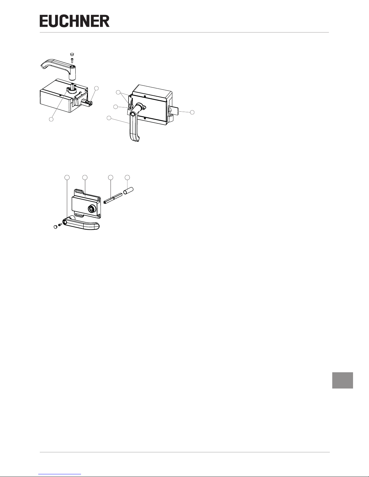
8.3.1. Preparing escape release
Prole width Length required for actuation
axis
Which EUCHNER parts are required? Necessary work steps
Without
mounting
plates
With mounting
plates
(4 mm each)
D D+9 D+17
30 mm 39 mm 47 mm Standard escape release
with 107 mm axis
(order no. 100465)
Shorten to required length
40 mm 49 mm 57 mm Standard escape release
with 107 mm axis
(order no. 100465)
If necessary,
extended actuation axis (order no. 106761)
Without mounting plates:
None
With mounting plates:
Use extended actuation axis and protective sleeve and
shorten to required length
45 mm 54 mm 62 mm Standard escape release
with 107 mm axis
(order no. 100465)
and
extended actuation axis (order no. 106761)
Use extended actuation axis and protective sleeve and
shorten to required length
50 mm 59 mm 67 mm Standard escape release
with 107 mm axis
(order no. 100465)
and
extended actuation axis (order no. 106761)
Use extended actuation axis and protective sleeve and
shorten to required length
55,5
M4
250
182
D + 9
D -1
D
11,5 55,5
Example without mounting plates:
Escape release
Handle module
Actuation axis Protective sleeve
(+4 mm per mounting plate)
(+4 mm per mounting plate)
1
Insert actuation axis. The snap ring A must be in contact with the escape release B.
2
Fit door handle.
3
Tighten xing screw to 2Nm and press in cap.
4
Fit protective sleeve.
1
3
2
4
A
B
Figure 7: Preparing escape release
Page 22

Operating Instructions Interlocking/Locking Modules
MGB2-I..-MLI-... / MGB2-L..-MLI-... (Modular)
22
(Translation of the original operating instructions) 2500234-01-08/18
9. Mounting
IMPORTANT
Ì Mounting must be performed only by authorized personnel.
Ì Depending on the substrate material, the detection range for the acquisition of the door position
may vary.
Ì During mounting, pay attention to correct alignment. Use the alignment aids on the housing for the
interlocking/locking module and on the housing for the handle module (see Figure 8).
With two-leaf hinged doors, one of the two door leaves must also be latched mechanically.
Use a rod latch (Item) or a double-door lock (Bosch Rexroth) for this purpose, for example.
For mounting steps , see Figure 8 and Figure 10 to Figure 15.
Attach system such that operation of the auxiliary release as well as inspection and maintenance are possible.
The locking screw must be screwed in and sealed again after mounting and after every use of the auxiliary release (original
set of seal labels order no. 155853). Tightening torque 0.5 Nm.
M6
T10
Figure 8: Installation example for door hinged on the right (general view)
Page 23

23
2500234-01-08/18 (Translation of the original operating instructions)
Operating Instructions Interlocking/Locking Modules
MGB2-I..-MLI-... / MGB2-L..-MLI-... (Modular)
EN
9.1. Replacing modules
CAUTION
Risk of damage to equipment or malfunctions as a result of uncontrolled machine stop.
Ì The communication within the system is interrupted by the replacement of a module and the safe
bits are reset. If a process is running, this situation can result in an uncontrolled stop and damage
to the installation or the product. Before replacement make sure the installation is in a suitable
operating status.
It is only possible to replace modules (e.g. locking module or extension module) in combination with a restart of the overall
system. On the disconnection of the module connection, the system enters into a fault state. The related module and all
downstream modules remain inactive until the overall system is restarted (fault state).
9.2. Mounting submodules
CAUTION
Risk of damage to equipment or malfunctions as a result of incorrect connection or a conguration
change.
Ì It is only possible to use submodules of connection types P, R and N. Check the compatibility before
installation. For the related connection type of a submodule, please refer to the sticker on the rear of
the submodule or the data sheet for the related submodule. This is included with each submodule.
Ì Pay attention to the alignment of the submodule. See marking (a) in Figure 9: Mounting submodule.
Submodules can also be installed rotated by 180°. The marking (a) always indicates the rst installation position. In the example, the emergency stop S1 is underneath.
Ì Make sure the pins on the submodule slide straight into the guide. Tighten the cover screws to
0.5Nm.
Ì On using a submodule with labeling elds, pay attention to the correct alignment of the modules in re-
lation to the labeling elds. Incorrect assignments can cause serious malfunctions in your installation.
Ì Make sure no foreign bodies, e.g. chips or wire enter the open slots on the submodule. These can
cause short circuits or contact problems.
Ì Avoid touching the contacts on the underside of the submodule. Risk of ESD damage and contact
problems due to soiling.
Ì Unused submodule slots must be tted with a cover (order number 126372).
Pos. 1
Pos. 2
Pos.
3
a
Figure 9: Mounting submodule
Page 24

Operating Instructions Interlocking/Locking Modules
MGB2-I..-MLI-... / MGB2-L..-MLI-... (Modular)
24
(Translation of the original operating instructions) 2500234-01-08/18
9.3. Replacing submodules
CAUTION
Risk of damage to equipment or malfunctions as a result of uncontrolled machine stop.
Ì The communication within the system is interrupted by the replacement of a submodule and the
safe bits are reset. If a process is running, this situation can result in an uncontrolled stop and
damage to the installation or the product. Before replacement make sure the installation is in a
suitable operating status.
NOTICE
Pay attention to the information on the replacement of a submodule in the operating instructions for
the related module. On submodules with a safety function, the correct function must be tested after
replacement before the system enters normal operation again.
The replacement of submodules MSM while in operation is also possible (pay attention to safety instruction above). As
soon as the system detects a correct submodule, the submodule is ready for operation. The system reacts as follows on
a replacement:
1. If the submodule MSM is removed, the SLOT LED illuminates red, interrupted by 1x green ash. In addition, the SF LED
on the bus module MBM illuminates red
2. If the submodule MSM contains a safety function, the related bit on the bus is cleared as soon as the submodule has
been removed
3. If an identical submodule is inserted with the same alignment, the fault display goes out and the bit is transmitted on the
bus again to suit the actual situation.
9.3.1. Replacing faulty submodules
Important!
If alignment detection is active, the system checks the alignment of the newly inserted submodule
and compares it to the submodule inserted last. The alignment of the previous submodule must be
retained in this situation because otherwise the conguration of the device will change. If a conguration
change is required, pay attention to the sequence in 9.3.2. Replacing submodule with a submodule
with a different function (changing conguration). You will nd information on switching on and off the
alignment detection in the operating instructions for your bus module MBM.
9.3.2. Replacing submodule with a submodule with a different function (changing conguration)
The system saves the last conguration of your system.
The conguration changes if
Ì You replace a submodule with a submodule with a different function or
Ì You t the same submodule rotated by 180°.
Adapt the conguration in the conguration software for your control system.
Then the new conguration must be taught-in by restarting the bus module MBM. You will nd further information in the
operating instructions for your bus module MBM.
Page 25

25
2500234-01-08/18 (Translation of the original operating instructions)
Operating Instructions Interlocking/Locking Modules
MGB2-I..-MLI-... / MGB2-L..-MLI-... (Modular)
EN
9.3.3. Fitting and removing lenses and labels for controls and indicators
1 2
2
3
90°
Click!
1
Fitting
Removing
Lens
Page 26

Operating Instructions Interlocking/Locking Modules
MGB2-I..-MLI-... / MGB2-L..-MLI-... (Modular)
26
(Translation of the original operating instructions) 2500234-01-08/18
10. Changing the door hinge position
10.1. Changing the interlocking/locking module to a different door hinge position
To change the interlocking/locking module for doors with a different door hinge position, the module only needs to be
rotated by 180°. Submodules installed in the module can also be rotated by 180° (see section 9.1. Replacing modules on
page 23 ).
10.2. Changing actuating direction of the handle module
(Here: from right to left)
Important!
It is possible to make this change only when the bolt tongue is not extended and an escape release
is not yet mounted.
As supplied, the handle module is set either for doors hinged on the right or for doors hinged on the left.
Based on the example of a handle module for doors hinged on the right this means:
Ì The guard opens by pressing down the door handle.
Ì The system is mounted the other way up for doors hinged on the left. In other words, the guard opens by pressing up
the door handle (see Figure 10). For this reason the actuating direction of the door handle must be changed (see Figure
10 to Figure 15).
(Similarly on handle modules for doors hinged on the left)
Page 27

27
2500234-01-08/18 (Translation of the original operating instructions)
Operating Instructions Interlocking/Locking Modules
MGB2-I..-MLI-... / MGB2-L..-MLI-... (Modular)
EN
CLOSED
OPEN
1
3
2
1
Press door handle up.
2
Unscrew locking screws.
3
Push cover aside.
Figure 10: Changing actuating direction, step
1
Figure 11: Changing actuating direction, steps 2 and
3
5
4
4
Lift the locking pin on the door handle using a screwdriver and hold
it in this position.
5
Turn door handle to the right.
6
a
b
7
8
6
Only if using an escape release: Using the Torx 10, turn the joint
counterclockwise from position (a) to position (b).
7
Close cover.
8
Screw in locking screws and tighten to 0.8 Nm.
Figure 12: Changing actuating direction, steps 4 and
5
Figure 13: Changing actuating direction, steps 6 to
8
T10
9
10
11
OPEN
CLOSED
9
Remove cap and undo screw.
AT
Reposition the door handle by 90° in clockwise direction and fasten it
again.
A
Tighten screw to 2Nm and re-t cap.
A
State after repositioning.
Figure 14: Changing actuating direction, steps 9 and
A
Figure 15: Changing actuating direction, nal state
Page 28

Operating Instructions Interlocking/Locking Modules
MGB2-I..-MLI-... / MGB2-L..-MLI-... (Modular)
28
(Translation of the original operating instructions) 2500234-01-08/18
11. Protection against environmental effects
Lasting and correct safety function requires that the system must be protected against foreign bodies such as swarf, sand,
blasting shot, etc., which can become lodged in the housing.
Pay attention to the following measures:
Ì Seal unused connections using the covers provided.
Ì Make sure the housing covers are correctly sealed and the cover screws are tightened to the necessary tightening
torque.
Ì Cover the device during painting work.
12. Controls and indicators
Figure 16: Indicators and controls
LED Description
POWER
Illuminated if power supply
correct Color: green
STATE
Indicates the device state
Color: green
LOCK
Indicates the state of the
guard locking
Color: yellow
DIA
Indicates faults
Color: red
SLOT 1
Indicates the status of the
submodule
Color: red/green
SLOT 2
Indicates the status of the
submodule
Color: red/green
Page 29

29
2500234-01-08/18 (Translation of the original operating instructions)
Operating Instructions Interlocking/Locking Modules
MGB2-I..-MLI-... / MGB2-L..-MLI-... (Modular)
EN
13. Electrical connection
All devices in a line of modules draw their power from a suitable bus module MBM. The connection is only allowed to be
made to a bus module MBM or an upstream module.
For detailed instructions on the connection of the overall system, please refer to the operating instructions for the bus
module MBM used.
CAUTION
Risk of damage to equipment or malfunctions as a result of incorrect connection.
Ì Pay attention to the instructions on correct connection in the operating instructions for the bus
module MBM used.
13.1. Connecting modules
MGB2-Modular modules can either be connected together directly or using cables (see Figure 17: Connecting modules).
Each module has a top and a bottom connection. You can use either the bottom or the top connection or both if the module
is between two other modules.
The bottom module connector is already integrated. To use the top connection, change the connector's position. Only use
the module connector intended to connect modules together (see table below). The maximum cable length for a line must
not exceed 20 m.
156718
157025
next module
direct plug
blind plug
stacklight
M12, 5-pin,
male
M12, 5-pin,
female
157024
MGB2-L...
MCM-...
direct plug
cable connect
157028
157029
next module
cable connect
(
M12, 5-pin,
female)
156718
157025
next module
direct plug
blind plug
157028
next module
cable connect
(
M12, 5-pin,
female)
Figure 17: Connecting modules
Table 2: Overview of module connectors
Page 30

Operating Instructions Interlocking/Locking Modules
MGB2-I..-MLI-... / MGB2-L..-MLI-... (Modular)
30
(Translation of the original operating instructions) 2500234-01-08/18
Function Order no. Included?
Module connector M12, 5-pin, male 157024 1x
Blanking cover 156718 1x
Set with sealing caps for unused connections 156739 Yes
Module connector, 5-pin, female for the direct connec-
tion of a further module
157025
No, must be ordered separately
Module connector M12, 5-pin, female for the connec-
tion of a further module via a connecting cable
157028
Module connector for the connection of a Stacklight 157029
Connecting cable M12, 5-pin See catalog or www.euchner.com
13.2. Using submodules
Each interlocking/locking module can contain up to two submodules. For an exact description of the individual submodules
as well as information on compatibility, please refer to the data sheet for the related submodule. This is included with each
submodule.
Important!
Ì In the modules described here it is only allowed to install submodules of connection types P, R and
N. For information on the related connection type of a submodule, please refer to the sticker on
the rear of the submodule or the data sheet for the related submodule. This is included with each
submodule.
Ì Only one submodule with an emergency stop is allowed to be installed per module
Ì On using a submodule with labeling elds, pay attention to the correct alignment of the modules in
relation to the labeling elds. Incorrect assignments can cause serious malfunctions in your installation.
Ì Unused submodule slots must be tted with a cover order number 126372.
Ì Avoid touching the contacts on the underside of the submodule. Risk of ESD damage and contact
problems due to soiling.
Page 31

31
2500234-01-08/18 (Translation of the original operating instructions)
Operating Instructions Interlocking/Locking Modules
MGB2-I..-MLI-... / MGB2-L..-MLI-... (Modular)
EN
14. Data blocks for interlocking/locking module MGB2-I or MGB2-L
Important!
You will nd the exact data structure for your device on the data sheet enclosed. You will nd a detailed
description of the safe and non-safe data blocks in the operating instructions for your bus module MBM.
15. Setup
The device is automatically in operation after powering up the bus module MBM. For detailed instructions on setup, please
refer to the operating instructions for your bus module MBM.
You can see the current operating status on the LEDs on the module (see 12. Controls and indicators on page 28 and
16. System status table, module LEDs on page 33). You will also nd information on fault detection there.
15.1. Teach-in operation (only for MGB2 unicode)
The handle module must be assigned to the locking module using a teach-in function before the system comprising interlocking/locking module and handle module forms a functional unit.
During a teach-in operation, the module is in the safe state (no safe bits are set).
Important!
Ì A system that has not yet been taught-in remains in the teach-in standby state until a handle mod-
ule has been taught in. Interlocking/locking modules already taught-in remain in the teach-in standby state for 3 min after the system start.
Ì The interlocking/locking module disables the code for the previous handle module if a new handle
module is taught-in. Teach-in is not possible again immediately for this handle module if a new
teach-in operation is carried out. The disabled code is deleted in the locking module only after a
third code has been taught-in.
Ì If the interlocking/locking module detects a disabled or unsuitable handle module while the module
is in the teach-in standby state, a teach-in fault is indicated after 30 s.
Ì The interlocking/locking module can only be operated with the last handle module taught-in.
Ì If, in the teach-in standby state, the interlocking/locking module detects the handle module last
taught-in, the teach-in standby state is ended immediately and the interlocking/locking module
changes to normal operation.
Ì If the bolt tongue is in the operating distance for less than 30 s, the handle module is not taught-in
and the device indicates a teach-in fault.
Teaching in handle module
1. Fit handle module.
2. Close guard. Check for correct alignment and distance using the markings on the interlocking/locking module and
re-adjust if necessary.
3. Insert bolt tongue in the interlocking/locking module.
4. Connect interlocking/locking module to the bus module MBM. The bus module must be in operation for this purpose.
¨ Teach-in operation starts, green LED (State) ashes slowly (approx. 1 Hz). During the teach-in operation, the locking
module checks whether the handle module is a disabled handle module. Provided this is not the case, the teach-in operation is completed after approx. 30 seconds, and the green LED (State) goes out. The new code has now been stored,
and the old code is disabled. The STATE and DIA LEDs on the interlocking/locking module ash alternately if the teach-in
operation was successful.
5. Restart overall system via the bus module MBM. For this purpose, disconnect the bus module from the power supply
for a few seconds.
Page 32

Operating Instructions Interlocking/Locking Modules
MGB2-I..-MLI-... / MGB2-L..-MLI-... (Modular)
32
(Translation of the original operating instructions) 2500234-01-08/18
15.2. Mechanical function test
It must be possible to insert the bolt tongue easily into the locking module. To check, close guard several times and actuate
door handle.
If available, check function of the escape release. With active guard locking it must be possible to operate the escape release
from the inside without excessive effort (approx. 5 Nm).
15.3. Electrical function test
1. Close all guards and insert the bolt tongue into the locking module.
2. Activate guard locking.
Ì The machine must not start automatically.
Ì It must not be possible to open the guard.
Ì For the MGB2-I.. the following applies: The green LED (State) is illuminated.
Ì For the MGB2-L.. the following applies:The green LED (State) and the yellow LED (Lock) are illuminated.
3. Enable operation in the control system.
Ì It must not be possible to deactivate guard locking as long as operation is enabled.
4. Disable operation in the control system and deactivate guard locking.
Ì The guard must remain locked until there is no longer any risk of injury.
Ì It must not be possible to start the machine as long as guard locking is deactivated.
Ì It must be possible to open the guard.
Repeat steps 2-4 for each guard.
15.4. Replacing a module
For instructions on replacement, please refer to the operating instructions for your bus module MBM. After the replacement
of an interlocking/locking module or a handle module, a teach-in operation may be necessary. See 15.1. Teach-in operation
(only for MGB2 unicode) on page 31.
Page 33

33
2500234-01-08/18 (Translation of the original operating instructions)
Operating Instructions Interlocking/Locking Modules
MGB2-I..-MLI-... / MGB2-L..-MLI-... (Modular)
EN
16. System status table, module LEDs
All diagnostic messages are listed below. The scope of the possible messages may differ depending on the type and number
of modules/submodules used.
16.1. System indications if there are faults (module LEDs)
If there are faults, the bit LM.E_G is set. After the fault has been rectied, it can be acknowledged using the bit LM.ACK_G.
The bit LM.E_G is reset during this process. Exception: escape release fault (see 19.2. Fault on actuating the escape
release on page 38)
Operating mode
LED indicator
Device diagnostics related fault/status bit
State
POWER (gn)
STATE (gn)
Lock (ye), only MGB2-L1/-L2
DIA (rd)
Fault display
1 x LM.E_G
Handle module teach-in fault (e.g. teach-in operation interrupted too early), conguration teach-in fault
3 x LM.E_G
Handle module read fault (e.g. fault in code or code cannot
be read)**
5 x LM.E_G
Environment fault, disabled actuator, power supply outside the
permissible range
LM.E_G Internal fault (e.g. component faulty, data error)*
1 x LM.E_ER
Plausibility fault, signal sequence incorrect,
e.g. broken bolt tongue recognized ***
or after actuation of the escape release, for example*
1 x
BM.E_MLI MLI communication fault (indication on bus module)
Key to symbols
LED not illuminated
LED illuminated
10 Hz, 8 s
LED ashes for 8 seconds at 10 Hz
3 x
LED ashes three times
X Any state
* Latching fault; use corresponding output bit LM.ACK_G to reset
** Non-latching fault; open guard and close it again to reset
*** Latching fault; use corresponding output bit LM.ACK_ER to reset, door must be open during this process (see chapter 16. System status table, module LEDs on page 33)
Important: If you do not nd the displayed device status in the System status table, this indicates an internal device fault. In this case, you should contact the manufacturer.
Page 34

Operating Instructions Interlocking/Locking Modules
MGB2-I..-MLI-... / MGB2-L..-MLI-... (Modular)
34
(Translation of the original operating instructions) 2500234-01-08/18
16.2. System indications during setup, teach-in and normal operation
Operating mode
LED indicator
Door position
Position of the bolt tongue
Guard locking control LM.FO_CL
(depending on setting also LM.O.CL)
Device diagnostics
status bit LM.I_OD
Bolt position
status bit LM.I_OT
Bolt position (SK)
safe input bit LM.FI_SK
Status bit LM.I_SK
Guard locking
status bit LM.I_OL
Guard locking status (ÜK)
safe input bit LM.FI_UK
Status bit LM.I_UK
State
POWER (gn)
STATE (gn)
Lock (ye), only MGB2-L1/-L2
DIA (rd)
Normal operation
long OFF
short ON
open
not
inserted
off off off off off off Normal operation, door open
long ON
short OFF
closed
not
inserted
off on off off off off Normal operation, door closed
long ON
short
OFF
closed inserted off on on on off off Normal operation, door closed, bolt tongue inserted
closed inserted on on on on on on Normal operation, door closed and locked
X
ashing
quickly
X
not
inserted
on off off off off off
Ready for guard locking, guard locking is active, bolt
tongue not inserted
Teach-in standby
(only for MGB2
unicode)
3 x open
not
inserted
off off off off off off
Door open; unit is ready for teach-in for another handle
module (only short time after power-up)
Setup
(only for MGB2
unicode)
1 Hz closed inserted on on on off on off Teach-in operation
alternately ash-
ing
STATE /DIA
X X off off off off off
Positive acknowledgment after completion of teach-in
operation
Key to symbols
LED not illuminated
LED illuminated
10 Hz, 8 s
LED ashes for 8 seconds at 10 Hz
3 x
LED ashes three times
X Any state
Important: If you do not nd the displayed device status in the System status table, this indicates an internal device fault. In this case, you should contact the manufacturer.
Page 35

35
2500234-01-08/18 (Translation of the original operating instructions)
Operating Instructions Interlocking/Locking Modules
MGB2-I..-MLI-... / MGB2-L..-MLI-... (Modular)
EN
17. System status table (slot LEDs)
If a fault occurs on the submodule, the bit LM.E_SM.. is set. As soon as the fault has been corrected, it is reset automatically
(non-latching fault).
Fault display
SLOT1 / SLOT2 LED
Meaning Measures
OFF A submodule is not used
or
Submodule functioning without faults
-
Red ON
Green ashes 1 x
Submodule missing although a submodule was included in the last conguration
Insert suitable submodule
or
Change conguration
Red ON
Green ashes 2 x
Submodule is installed rotated by 180° Case 1: Type of submodule is correct, but must be installed rotated by 180°. Case 2:
If it is intended to change the conguration, the system must be restarted so that the
required conguration is taught-in.
Case 3: Alignment is irrelevant for this submodule, however the parameter for
alignment detection is active. Change parameter for alignment detection and restart
system.
Red ON
Green ashes 3 x
Submodule does not correspond to the submodule
type congured last
Insert submodule of appropriate type
or
Change conguration
Red ON Internal fault in the submodule Replace submodule.
Ì If the problem persists: replace base unit
Red ashing (1Hz)
The DIA LED also
illuminates
Fault in the safety equipment, can be reset automatically
Ì Enabling switch discrepancy fault
Ì Other input fault on the submodule
For enabling switch:
release enabling switch and press again.
Ì If the problem persists: check cable and connection.
Ì If the problem persists: replace submodule.
Ì If the problem persists: replace base unit
For all other submodules:
replace submodule.
Ì If the problem persists: replace base unit
Page 36

Operating Instructions Interlocking/Locking Modules
MGB2-I..-MLI-... / MGB2-L..-MLI-... (Modular)
36
(Translation of the original operating instructions) 2500234-01-08/18
18. Technical data
NOTICE
If a data sheet is included with the product, the information on the data sheet applies.
Parameter Value
Housing material Fiber glass reinforced plastic
Die-cast zinc, nickel-plated,
Stainless steel,
Powder-coated sheet steel
Dimensions See dimension drawing
Weight MGB2 (interlocking/locking module, without submodules) 1.0 kg
Weight handle module 1.1 kg
Weight escape release module 0.55 kg
Ambient temperature -25 … +55 °C
Degree of protection IP 65 1)
Safety class III
Degree of contamination 3
Installation position Any
Locking force Fzh acc. to GS-ET-19 2000 N
Power supply Via bus module MBM
Connection M12, 5-pin (EUCHNER module plug connector MLI)
Current consumption, max.
2)
500 mA
Rated impulse withstand voltage U
imp
0.5 kV
Resilience to vibration and shock Acc. to EN60947-5-3
EMC protection requirements Acc. to EN61000-4
and DINEN61326-3-1
Risk times, max. (switch-off times)
3)
- Monitoring of the position of the guard
- Monitoring of guard locking
- Activation of guard locking
See information in the operating instructions for your bus module
Reliability values acc. to ENISO13849-1:2005
Category 4
Performance Level PL e
MTTFd
4)
820 years
DC 99%
Mission time 20 years
PFHd
4)
- Monitoring of guard locking and the position of the guard
- Control of guard locking
- Monitoring of the position of the guard
- Evaluation of safety signals in submodules installed
2.62 x 10
-9
1) Only with correctly mounted connecting cables and submodules
2) Without submodules.
3) The risk time is the max. time between the change in the input status and the deletion of the corresponding bit in the bus protocol.
4) Fixed failure rate without consideration of faults in wearing parts.
Page 37

37
2500234-01-08/18 (Translation of the original operating instructions)
Operating Instructions Interlocking/Locking Modules
MGB2-I..-MLI-... / MGB2-L..-MLI-... (Modular)
EN
18.1. Radio frequency approvals
FCC ID: 2AJ58-02
IC: 22052-02
FCC/IC-Requirements
This device complies with part 15 of the FCC Rules and with Industry Canada’s licence-exempt RSSs. Operation is subject
to the following two conditions:
1) This device may not cause harmful interference, and
2) this device must accept any interference received, including interference that may cause undesired operation.
Changes or modications not expressly approved by the party responsible for compliance could void the user‘s authority
to operate the equipment.
NOTE: This equipment has been tested and found to comply with the limits for a Class A digital device, pursuant to part 15 of
the FCC Rules. These limits are designed to provide reasonable protection against harmful interference when the equipment
is operated in a commercial environment. This equipment generates, uses, and can radiate radio frequency energy and, if
not installed and used in accordance with the instruction manual, may cause harmful interference to radio communications.
Operation of this equipment in a residential area is likely to cause harmful interference in which case the user will be required
to correct the interference at his own expense.
Le présent appareil est conforme aux CNR d’Industrie Canada applicables aux appareils radio exempts de licence. L’exploitation est autorisée aux deux conditions suivantes :
(1) l’appareil ne doit pas produire de brouillage, et
(2) l’utilisateur de l’appareil doit accepter tout brouillage radioélectrique subi, même si le brouillage est susceptible d’en
compromettre le fonctionnement.
Page 38

Operating Instructions Interlocking/Locking Modules
MGB2-I..-MLI-... / MGB2-L..-MLI-... (Modular)
38
(Translation of the original operating instructions) 2500234-01-08/18
19. Troubleshooting and assistance
You will nd detailed information on diagnostics and troubleshooting in the operating instructions for your bus module MBM.
The following information only covers faults related to the interlocking/locking module MGB2.
19.1. Resetting general faults
Proceed as follows:
1. Acknowledge fault using output bit LM.ACK_G.
2. Close guard if necessary and switch on guard locking.
¨ The system is in normal operation again.
19.2. Fault on actuating the escape release
This fault behavior must be congured correspondingly in the parameters. For this purpose you must set the value in the
Fehler bei Betätigung der Fluchtentriegelung eld to ja in the Baugruppenparameter dialog box in the Fehler Fluchtentriegelung section in the conguration software for your control system. You will nd information on conguration in the operating
instructions for your bus module MBM.
To achieve monitoring of the locking element in category 4, PL e according to ENISO13849-1, internal monitoring logic is
integrated into every locking module.
Result: The MGB2 system enters into a latching fault on the actuation of the escape release (see 16.2. System indications
during setup, teach-in and normal operation on page 34).
The bit LM.ACK_ER must be set for at least 100 ms to acknowledge the fault.
Door position
Position of the bolt tongue
Guard locking
Bolt position status bit LM.I_OT
Guard locking status bit LM.I_OL
ÜK input bit LM.FI_UK
Device diagnostics status bit LM.I_OD
LED indicator
State
Power (gn)
State (gn)
Lock (ye)
DIA (rd)
X X X off off off X 1 x
Signal sequence incorrect (e.g. after actuation of the escape
release)*
LED not illuminated
LED illuminated
10 Hz (8 s)
LED ashes for 8 seconds at 10 Hz
3 x
LED ashes three times
X Any state
19.3. Resetting system to factory settings
For instructions on resetting to factory settings, please refer to the operating instructions for your bus module MBM.
Page 39

39
2500234-01-08/18 (Translation of the original operating instructions)
Operating Instructions Interlocking/Locking Modules
MGB2-I..-MLI-... / MGB2-L..-MLI-... (Modular)
EN
20. Service
If service support is required, please contact:
EUCHNER GmbH + Co. KG
Kohlhammerstraße 16
D-70771 Leinfelden-Echterdingen
Service telephone:
+49 711 7597-500
E-mail:
support@euchner.de
Internet:
www.euchner.com
21. Inspection and service
WARNING
Loss of the safety function because of damage to the device.
In case of damage, the affected module must be replaced completely. Only accessories or spare parts
that can be ordered from www.euchner.com may be replaced.
Regular inspection of the following is necessary to ensure trouble-free long-term operation:
Ì Check the safety function (see chapter 15.3. Electrical function test on page 32)
Ì Check the secure fastening of the devices and the connections
Ì Check for soiling
No servicing is required. Repairs to the device are only allowed to be made by the manufacturer.
NOTICE
The year of manufacture can be seen in the lower right corner of the type label.
Page 40

Operating Instructions Interlocking/Locking Modules
MGB2-I..-MLI-... / MGB2-L..-MLI-... (Modular)
40
(Translation of the original operating instructions) 2500234-01-08/18
22. Declaration of conformity
24.07.2018 - NG -KJ - Blatt/Sheet/ Page/Pagina/ Página 1
EUCHNER GmbH + Co. KG Kohlham merstraße 16 70771 Leinfelden-Echterdingen Tel. +49/711/7597-0 Fax +49/711/753316 www.euchner.de info@euchner.de
EU-Konformitätserklärung
Original DE
EU declaration of conformity
Translation EN
Déclaration UE de conformité
Traduction FR
Dichiarazione di conformità UE
Traduzione IT
Declaración UE de conformidad
Traducción ES
Die nachfolgend aufgeführten Produkte sind konform mit den Anforderungen der folgenden Richtlinien (falls zutreffend):
The beneath listed products are in conformity with the requirements of the following directives (if applicable):
Les produits mentionnés ci-dessous sont conformes aux exigences imposées par les directives suivantes (si valable)
I prodotti sotto elencati sono conformi alle direttive sotto riportate (dove applicabili):
Los productos listados a continuación son conforme a los requisitos de las siguientes directivas (si fueran aplicables):
I:
Maschinenrichtlinie
Machinery directive
Directive Machines
Direttiva Macchine
Directiva de máquinas
2006/42/EG
2006/42/EC
2006/42/CE
2006/42/CE
2006/42/CE
II:
Funkanlagen-Richtlinie (RTTE / RED)
Radio equipment directive
Directive équipement radioélectrique
Direttiva apparecchiatura radio
Directiva equipo radioeléctrico
2014/53/EU
2014/53/EU
2014/53/UE
2014/53/UE
2014/53/UE
III:
RoHS Richtlinie
RoHS directive
Directive de RoHS
Direttiva RoHS
Directiva RoHS
2011/65/EU
2011/65/EU
2011/65/UE
2011/65/UE
2011/65/UE
Die Schutzziele der Niederspannungsrichtlinie 2014/35/EU und EMV Richtlinie 2014/30/EU werden gemäß Artikel 3.1 der FunkanlagenRichtlinie eingehalten.
The safety objectives of the Low-voltage directive 2014/35/EU and EMC Directive 2014/30/EU comply with article 3.1 of the Radio equipment
directive.
Les objectifs de sécurité de la Directive basse tension 2014/35/UE et Directive de CEM 2014/30/EU sont conformes à l'article 3.1 de la
Directive équipement radioélectrique.
Gli obiettivi di sicurezza della Direttiva bassa tensione 2014/35/UE e Direttiva CEM 2014/30/UE sono conformi a quanto riportato nell´articolo
3.1 della Direttiva apparecchiatura radio.
Los objetivos de seguridad de la Directiva de bajo voltaje 2014/35/UE y Directiva CEM 2014/30/UE cumplen con el artículo 3.1 de la Directiva
equipo radioeléctrico.
Folgende Normen sind angewandt:
a:
EN 60947-5-3:2013
Following standards are used:
b:
EN ISO 14119:2013
Les normes suivantes sont appliquées:
c:
EN ISO 13849-1:2015
Vengono applicate le seguenti norme:
d:
EN 60947-5-5:1997 + A1:2005 + A11:2013 + A2:2017
Se utilizan los siguientes estándares:
e:
EN 50364:2010
f:
EN 300 330 V2.1.1
g:
EN 50581:2012 (RoHS)
Bezeichnung der Bauteile
Type
Richtlinie
Normen
Zertifikats-Nr.
Description of components
Type
Directives
Standards
No. of certificate
Description des composants
Type
Directive
Normes
Numéro du certificat
Descrizione dei componenti
Tipo
Direttiva
Norme
Numero del certificato
Descripción de componentes
Typo
Directivas
Estándares
Número del certificado
Sicherheitsschalter
Safety Switches
Interrupteurs de sécurité
Finecorsa di sicurezza
Interruptores de seguridad
MGB2-I…
MGB2-L…
MGB2-H…
MBM…
MCM…
MSM…
I, II a, b, c, e, f, g Z10 18 xxxxx
Sicherheitsschalter mit Not-Halt-Einrichtungen
Safety Switches with Emergency-Stop facilities
Interrupteurs de sécurité avec appareillage arrêt d'urgence
Finecorsa di sicurezza con dispositivi di arresto di emergenza
Interruptores de seguridad con dispositivos de parada de
emergencia
MGB2-I…
MGB2-L…
MCM…
MSM…
I, II a, b, c, d , e, f, g Z10 18 xxxxx
Benannte Stelle
Notified Body
Organisme notifié
Sede indicata
Entidad citada
NB 0123
TÜV SÜD Product Service GmbH
Ridlerstrasse 65
80339 München
Germany
2518509-01–07/18
Page 41

41
2500234-01-08/18 (Translation of the original operating instructions)
Operating Instructions Interlocking/Locking Modules
MGB2-I..-MLI-... / MGB2-L..-MLI-... (Modular)
EN
24.07.2018 - NG -KJ - Blatt/Sheet/ Page/Pagina/ Página 2
EUCHNER GmbH + Co. KG Kohlham merstraße 16 70771 Leinfelden-Echterdingen Tel. +49/711/7597-0 Fax +49/711/753316 www.euchner.de info@euchner.de
Leinfelden, Juli 2018
i.A. Dipl.-Ing. Richard Holz
i.A. Dipl.-Ing. (FH) Duc Binh Nguyen
Leiter Elektronik-Entwicklung
Dokumentationsbevollmächtigter
EUCHNER GmbH + Co. KG
Manager Electronic Development
Documentation manager
Kohlhammerstraße 16
Responsable Développement Électronique
Responsable documentation
70771 Leinfelden-Echterdingen
Direttore Sviluppo Elettronica
Responsabilità della documentazione
Germany
Director de desarrollo electrónico
Agente documenta
Die alleinige Verantwortung für die Ausstellung dieser Konformitätserklärung trägt der Hersteller:
This declaration of conformity is issued under the sole responsibility of the manufacturer:
La présente déclaration de conformité est établie sous la seule responsabilité du fabricant:
La presente dichiarazione di conformità è rilasciata sotto la responsabilità esclusiva del fabbricante:
La presente declaración de conformidad se expide bajo la exclusiva responsabilidad del fabricante:
EUCHNER GmbH + Co. KG
Kohlhammerstraße 16
70771 Leinfelden-Echterdingen
Germany
Page 42

Euchner GmbH + Co. KG
Kohlhammerstraße 16
D-70771 Leinfelden-Echterdingen
info@euchner.de
www.euchner.com
Edition:
2500234-01-08/18
Title:
Operating Instructions Interlocking/Locking Modules
MGB2-I..-MLI-... / MGB2-L..-MLI-... (Modular) and from V1.00.0
(Translation of the original operating instructions)
Copyright:
© EUCHNER GmbH + Co. KG, 08/2018
Subject to technical modications; no responsibility is accepted for the accuracy of this information.
 Loading...