

Page 1
DE
EN
Betriebsanleitung
Operating Instructions
Lichtgitter/ Lichtvorhänge
LCA 4
Light Grids/ Light Curtains
LCA 4
Page 2

Betriebsanleitung
Lichtgitter/ Lichtvorhänge LCA 4
2
(Originalbetriebsanleitung) 2504709-01-06/17
Inhalt
1. Zu diesem Dokument ............................................................................................ 4
1.1. Gültigkeit .......................................................................................................................................4
1.2. Zielgruppe ......................................................................................................................................4
1.3. Zeichenerklärung ............................................................................................................................4
1.4. Ergänzende Dokumente ..................................................................................................................4
2. Bestimmungsgemäßer Gebrauch .......................................................................... 5
3. Beschreibung der Sicherheitsfunktion ................................................................... 6
4. Haftungsausschluss und Gewährleistung ................................................................ 6
5. Allgemeine Sicherheitshinweise ............................................................................. 7
6. Funktion ............................................................................................................... 8
6.1. Ausführungen im Überblick ..............................................................................................................9
6.2. Test-Funktion ................................................................................................................................10
6.2.1. Aktivierung der Test Funktion ............................................................................................10
6.3. Master-Slave Funktion ...................................................................................................................10
6.3.1. Beispielanwendung Hintertretschutz ..................................................................................11
6.3.2. Rückführkreis Anbindung ..................................................................................................11
6.4. LED-Anzeigen ...............................................................................................................................12
6.5. Sicherheitsausgänge .....................................................................................................................13
7. Montage ............................................................................................................. 14
7.1. Sicherheitsabstand Lichtvorhänge (horizontale Montage)..................................................................15
7.2. Sicherheitsabstand Lichtvorhänge (vertikale Montage) .....................................................................16
7.3. Sicherheitsabstand Lichtgitter (vertikale Montage) ...........................................................................18
7.4. Installation ....................................................................................................................................19
7.5. Positionierung ..............................................................................................................................19
7.6. Nutzbare Reichweite bei besonderen Umgebungsbedingungen .........................................................20
7.7. Einsatz von mehreren Schutzeinrichtungen (Multiple Systeme) ..........................................................20
7.8. Positionierung Master/Slave ..........................................................................................................22
7.9. Montieren und Ausrichten ..............................................................................................................23
7.10. Optische Ausrichtung ...................................................................................................................24
7.11. Verwendung von Umlenkspiegeln ...................................................................................................25
7.12. Abstand von reflektierenden Flächen .............................................................................................27
Page 3

3
2504709-01-06/17 (Originalbetriebsanleitung)
Betriebsanleitung
Lichtgitter/ Lichtvorhänge LCA 4
DE
8. Elektrischer Anschluss ........................................................................................ 29
8.1. Senderanschlüsse ........................................................................................................................29
8.1.1. LCA 4 (Mit Integrierten Steuerfunktionen) – LCA 4 Master Primärverbinder M12, 5-polig ........ 29
8.1.2. LCA 4 Slave 1 / LCA 4 Slave 2 – Primärverbinder M12, 5-polig ...........................................30
8.1.3. LCA 4 Master – Sekundärverbinder M12, 5-polig
LCA 4 Slave 2 – Sekundärverbinder M12, 5-polig ...............................................................30
8.2. Empfängeranschlüsse ...................................................................................................................30
8.2.1. LCA 4 (Modelle mit integrierten Steuerfunktionen) – Verbinder M12, 8-polig
LCA 4 Master – Primärverbinder M12, 8-polig ....................................................................30
8.2.2. LCA 4 Slave 1 / LCA 4 Slave 2 – Primärverbinder M12, 5-polig ...........................................30
8.2.3. LCA 4 Master – Sekundärverbinder M12, 5-polig
LCA 4 Slave 2 – Sekundärverbinder M12, 5-polig ...............................................................31
9. Betriebsarten/ Inbetriebnahme ............................................................................ 32
9.1. Konfiguration und Betriebsarten (Modelle Master/mit integrierten Steuerfunktionen) ........................... 32
9.1.1. Betriebsart Manuell ..........................................................................................................32
9.1.2. Betriebsart Automatik .......................................................................................................32
9.1.3. Anschluss externe Schütze K1 und K2 ..............................................................................33
9.1.4. Anschlussbeispiele mit Sicherheitsmodulen ........................................................................33
10. Diagnose/ Fehlerbehebung ................................................................................. 38
11. Technische Daten ............................................................................................... 39
11.1. Maßzeichnungen ...........................................................................................................................42
12. Bestellinformationen und Zubehör ....................................................................... 43
13. Kontrolle und Wartung ........................................................................................ 44
13.1. Funktionskontrollen .......................................................................................................................44
13.2. Reinigung .....................................................................................................................................44
13.3. Wartung .......................................................................................................................................45
14. Service .............................................................................................................. 46
15. Konformitätserklärung ........................................................................................ 47
Page 4
Betriebsanleitung
Lichtgitter/ Lichtvorhänge LCA 4
4
(Originalbetriebsanleitung) 2504709-01-06/17
1. Zu diesem Dokument
1.1. Gültigkeit
Diese Betriebsanleitung gilt für Lichtgitter und Lichtvorhänge der Baureihe LCA, Typ 4. Diese Betriebsanleitung bildet zusammen mit ggf. beiliegenden Kurzanleitungen die vollständige Benutzerinformation für Ihr Gerät.
1.2. Zielgruppe
Konstrukteure und Anlagenplaner für Sicherheitseinrichtungen an Maschinen, sowie Inbetriebnahme- und Servicefachkräfte,
die über spezielle Kenntnisse im Umgang mit Sicherheitsbauteilen verfügen.
1.3. Zeichenerklärung
Zeichen/Darstellung Bedeutung
Dokument in gedruckter Form
www
Dokument steht unter www.euchner.de zum Download bereit
GEFAHR
WARNUNG
VORSICHT
Sicherheitshinweise
Gefahr von Tod oder schweren Verletzungen
Warnung vor möglichen Verletzungen
Vorsicht leichte Verletzungen möglich
HINWEIS
Wichtig!
Hinweis auf mögliche Geräteschäden
Wichtige Information
Tipp Tipp/nützliche Informationen
1.4. Ergänzende Dokumente
Die Gesamtdokumentation für dieses Gerät besteht aus folgenden Dokumenten:
Dokumenttitel
(Dokumentnummer)
Inhalt
Betriebsanleitung
Lichtgitter/ Lichtvorhänge
LCA 4
(2504709)
(dieses Dokument)
ggf. beiliegende Kurzanleitungen
Artikelspezifische Information zu Abweichungen oder Ergänzungen
Wichtig!
Lesen Sie immer alle Dokumente durch, um einen vollständigen Überblick für die sichere Installation, Inbetriebnahme und Bedienung des Geräts zu bekommen. Die Dokumente können unter
www.euchner.de heruntergeladen werden. Geben Sie hierzu die Dok. Nr. in die Suche ein.
Page 5

5
2504709-01-06/17 (Originalbetriebsanleitung)
Betriebsanleitung
Lichtgitter/ Lichtvorhänge LCA 4
DE
2. Bestimmungsgemäßer Gebrauch
Lichtgitter und Lichtvorhänge der Baureihe LCA sind optoelektronische Schutzeinrichtungen.
Sie stellen gemäß EN61496-1, berührunglos wirkende Schutzeinrichtungen des Typs 4 zum Schutz von Personen dar.
Das bedeutet:
Ì Einschaltbefehle, die eine gefährliche Maschinenfunktion hervorrufen, dürfen erst dann wirksam werden, wenn die Si-
cherheitsausgänge des Empfängers aktiv sind.
Ì Das Unterbrechen eines einzelnen oder mehrerer Lichtstrahlen, löst einen Stoppbefehl aus.
Vor dem Einsatz des Geräts ist eine Risikobeurteilung an der Maschine durchzuführen z. B. nach folgenden Normen:
Ì ENISO13849-1, Sicherheitsbezogene Teile von Steuerungen
Ì ENISO12100, Sicherheit von Maschinen – Allgemeine Gestaltungsleitsätze – Risikobeurteilung und Risikominderung
Ì EN61496-1, Sicherheit von Maschinen - Berührungslos wirkende Schutzeinrichtungen - Teil 1: Allgemeine Anforderungen
und Prüfungen
Ì IEC62061, Sicherheit von Maschinen – Funktionale Sicherheit sicherheitsbezogener elektrischer, elektronischer und
programmierbarer elektronischer Steuerungssysteme.
Zum bestimmungsgemäßen Gebrauch gehört das Einhalten der einschlägigen Anforderungen für den Einbau und Betrieb,
insbesondere nach folgenden Normen:
Ì ENISO13849-1, Sicherheitsbezogene Teile von Steuerungen
Ì EN60204-1, Elektrische Ausrüstung von Maschinen
Ì EN61496-2 – Sicherheit von Maschinen - Berührungslos wirkende Schutzeinrichtungen - Teil 2: Besondere Anforderun-
gen an Einrichtungen, welche nach dem aktiven opto-elektronischen Prinzip arbeiten
Ì ENISO13855-1 - Sicherheit von Maschinen - Anordnung von Schutzeinrichtungen im Hinblick auf Annäherungsgeschwin-
digkeiten von Körperteilen
Geräte der Baureihe LCA dürfen nur in Verbindung mit den vorgesehenen Komponenten der LCA-Familie kombiniert werden.
Die Verschaltung mehrerer Geräte in Reihe, darf nur mit Geräten erfolgen, die für die Reihenschaltung mit Geräten der
Baureihe LCA vorgesehen sind. Prüfen Sie dies in der Betriebsanleitung des entsprechenden Geräts. Eine Kombination mit
Lichtgittern oder Lichtvorhängen anderer Hersteller ist nicht zulässig.
Es dürfen maximal 3 Geräte in einer Reihenschaltung betrieben werden.
Wichtig!
Der Anwender trägt die Verantwortung für die korrekte Einbindung des Geräts in ein sicheres Gesamtsystem.
Dazu muss das Gesamtsystem z.B. nach ENISO13849-2 validiert werden.
1. LCA 4 TR (mit integrierten Zusatzfunktionen)
Geräte der Baureihe LCA 4 bestehen aus Sender und Empfänger. Interne Zusatzfunktionen ermöglichen eine Kontrolle des
Feedbacks externer Schütze, die Verwaltung des manuellen/automatischen Betriebs sowie die Einstellung unterschiedlicher
Reichweiten.
2. LCA 4 TR M/S (MASTER/SLAVE)
Geräte der Baureihe LCA 4 bestehen aus zwei bis max. drei Sender - Empfänger Paaren. Die Paare bestehen aus einem
MASTER-Gerät und ein bis zwei SLAVE Geräten. Diese sind in Reihe geschaltet.
LED-Anzeigen auf Sender und Empfänger ermöglichen eine Diagnose des Systemzustands.
Interne Fehler werden vom Gerät ausgewertet.
Page 6

Betriebsanleitung
Lichtgitter/ Lichtvorhänge LCA 4
6
(Originalbetriebsanleitung) 2504709-01-06/17
Wichtig!
Ì Die Geräte des Typs LCA sind für den Einsatz in Stopp-Kategorie 1 vorgesehen.
Ì Der Einsatz in Stopp-Kategorie 0 ist nur unter Einhaltung der erforderlichen Sicherheitsabstände
erlaubt.
Ì Die Geräte bieten keinen Schutz vor physischen Gefährdungen (Herausschleudern von Teilen, Hit-
ze, Strahlung). In diesem Fall ist eine trennende Schutzeinrichtung vorzusehen.
3. Beschreibung der Sicherheitsfunktion
Geräte dieser Baureihe verfügen über folgende Sicherheitsfunktion:
Das sichere Erkennen einer Unterbrechung des Schutzfelds
Sicherheitsfunktion:
Bei Unterbrechung des Schutzfelds werden die Sicherheitsausgänge abgeschaltet.
Sicherheitskennwerte:
Kategorie, Performance Level, PFHD, SIL
4. Haftungsausschluss und Gewährleistung
Wenn die o.g. Bedingungen für den bestimmungsgemäßen Gebrauch nicht eingehalten werden oder wenn die Sicherheitshinweise nicht befolgt werden oder wenn etwaige Wartungsarbeiten nicht wie gefordert durchgeführt werden, führt dies zu
einem Haftungsausschluss und dem Verlust der Gewährleistung.
Page 7

7
2504709-01-06/17 (Originalbetriebsanleitung)
Betriebsanleitung
Lichtgitter/ Lichtvorhänge LCA 4
DE
5. Allgemeine Sicherheitshinweise
Sicherheitssysteme erfüllen Personenschutzfunktion.
Unsachgemäßer Einbau oder Manipulation, können zu tödlichen Verletzungen von Personen führen.
Prüfen Sie die sichere Funktion der Schutzeinrichtung insbesondere:
Ì nach jeder Inbetriebnahme
Ì nach jedem Austausch einer System-Komponente
Ì nach längerer Stillstandszeit
Ì nach jedem Fehler
Unabhängig davon sollte die sichere Funktion der Schutzeinrichtung in geeigneten Zeitabständen als Teil des Wartungsprogramms durchgeführt werden.
Wichtig!
Ì Lesen Sie vor Gebrauch die Betriebsanleitung und bewahren Sie diese sorgfältig auf.
Ì Stellen Sie sicher, dass die Betriebsanleitung bei Montage, Inbetriebnahme und Wartungsarbeiten
jederzeit zur Verfügung steht.
Ì Die Betriebsanleitung können Sie unter www.euchner.de herunterladen.
WARNUNG
Ì Das Gerät darf nur von einer sicherheitstechnisch geschulten Elektrofachkraft eingebaut, ange-
schlossen und in Betrieb gesetzt werden.
Ì Zutreffende technische Normen im Rahmen der jeweiligen Anwendung berücksichtigen.
Ì Bei der Installation sind die Anforderungen der Norm EN 60204 und ISO 13855 zu berücksichti-
gen.
Ì Bei Fehlfunktion des Gerätes, setzen Sie sich mit dem Hersteller in Verbindung.
Eingriffe in das Gerät sind nicht zulässig.
Ì Vor Beginn der Arbeiten ist das Gerät extern spannungsfrei zu schalten.
Unabhängig versorgte Relais-Lastkreise müssen abgeschaltet sein.
Ì Nach der Installation des Systems ist eine komplette Funktionsprüfung durchzuführen.
Ì Das Gerät darf nur in den spezifizierten Umgebungsbedingungen eingesetzt werden.
Besondere Umgebungsbedingungen sind beim Hersteller anzufragen.
Page 8
Betriebsanleitung
Lichtgitter/ Lichtvorhänge LCA 4
8
(Originalbetriebsanleitung) 2504709-01-06/17
6. Funktion
Die Geräte der Baureihe LCA bestehen aus Sender (S) und Empfänger (E). Der Sender schickt Infrarot-Lichtstrahlen zum
Empfänger. Diese bilden ein Schutzfeld um gefährliche Bereiche zu überwachen.
Wird mindestens ein Lichtstrahl des Schutzfelds unterbrochen, schalten die Sicherheitsausgänge des Empfängers ab.
Die Größe des Schutzfeldes ist abhängig von der Reichweite und der Schutzfeldhöhe.
Reichweite
Schutzfeldhöhe
Aufl ösung Lichtvorhang
Bild 1: LCA Schutzfeld
Die Auflösung des Gerätes definiert, welche Größe ein Gegenstand aufweisen muss, damit mindestens ein Lichtstrahl
unterbrochen wird.
Die Auflösung wird mit folgender Formel berechnet:
Linsendurchmesser + Linsenabstand = Auösung
CA
B
Sender (S) Empfänger (R)
Variable Denition
A Linsendurchmesser
B Linsenabstand
C Auflösung
Bild 2: LCA Auflösung
Page 9
9
2504709-01-06/17 (Originalbetriebsanleitung)
Betriebsanleitung
Lichtgitter/ Lichtvorhänge LCA 4
DE
Es werden zwei Gerätetypen unterschieden:
Lichtgitter bauen ein Schutzfeld aus 2–4 Lichtstrahlen auf. Aufgrund des großen Abstandes zwischen den einzelnen
Lichtstrahlen sind diese nur für den Körperschutz verwendbar.
Lichtvorhänge bestehen aus einer Vielzahl an Lichtstrahlen. Diese können je nach Auflösung (14–50mm) für die Erfassung
unterschiedlicher Körperteile eingesetzt werden. Unterschieden wird hierbei in Finger-, Hand- und Körperschutz.
Lichtgitter
2 - 4 Lichtstrahlen
Lichtvorhang
Vielzahl an Lichtstrahlen, Angabe als »Aufl ösung«
Bild 3: Lichtgitter, Lichtvorhang
6.1. Ausführungen im Überblick
Lichtvorhänge LCA 4 sind in folgenden Auflösungen erhältlich:
Ì 14mm (geschützte Höhen von 160mm bis 1810mm) FINGERSCHUTZ
Ì 30mm (geschützte Höhen von 160mm bis 1810mm) HANDSCHUTZ
Ì 40mm (geschützte Höhen von 160mm bis 1810mm) HANDSCHUTZ
Ì 50mm (geschützte Höhen von 160mm bis 1810mm) ARM,- UND BEINSCHUTZ
Lichtgitter LCA 4 sind in folgenden Ausführungen erhältlich:
Ì 2 Strahlen (je 500mm Abstand zwischen den Strahlen) KÖRPERSCHUTZ / ZUGANGSKONTROLLE
Ì 3 Strahlen (je 400mm Abstand zwischen den Strahlen) KÖRPERSCHUTZ / ZUGANGSKONTROLLE
Ì 4 Strahlen (je 300mm Abstand zwischen den Strahlen KÖRPERSCHUTZ / ZUGANGSKONTROLLE
Tabelle 1: Begriffserklärung
Begriff Denition
Auflösung Linsenabstand + Linsendurchmesser
BWS Berührungslos wirkende Schutzeinrichtung
FE Erdanschluss
FO1A / FO1B Sicherheitsausgänge
Master Primäres Sender-/Empfänger Paar
Slave Sekundäres Sender-/ Empfänger Paar
Multiple Systeme Einsatz von mehreren LCA-Systemen parallel
Tabelle 2: Typbezeichnungen
Bezeichnung Denition
LCA 4 T Sendereinheit
LCA 4 R Empfängereinheit
LCA 4 TR Sender-/Empfänger Set
LCA 4 TR M Sender-/Empfänger Set in Konfiguration Master
LCA 4 TR S1 Sender-/Empfänger Set in Konfiguration Slave 1
LCA 4 TR S1 Sender-/Empfänger Set in Konfiguration Slave 2
Page 10
Betriebsanleitung
Lichtgitter/ Lichtvorhänge LCA 4
10
(Originalbetriebsanleitung) 2504709-01-06/17
6.2. Test-Funktion
Die Test Funktion ermöglicht die Prüfung der Schutzfunktion unabhängig von der Maschinenfunktion.
Über eine simulierte Unterbrechung werden die Sicherheitsausgänge deaktiviert. Eine externe Steuerungseinheit kann den
Betrieb des Gesamtsystems prüfen, indem die angeschlossenen nachgeschalteten Geräte geprüft werden. Die Test Funktion
bleibt aktiv bis die Umschaltung in den Normalbetrieb erfolgt.
HINWEIS
Um die Test Funktion zu aktivieren, müssen die Pins 2 und 4 mindestens für 4ms stromlos (0V)
gesetzt werden.
6.2.1. Aktivierung der Test Funktion
1. Verbinden Sie PIN 2 und PIN 4 mit 0V.
Der Sender erkennt auf den Pins 0VDC und simuliert eine Unterbrechung. Die Sicherheitsausgänge schalten ab. Der
Empfänger wechselt in den Stopp-Zustand.
Die LED TEST am Sender leuchtet konstant orange.
Die LED STOP am Empfänger leuchtet konstant rot.
Siehe Kapitel: LED-Anzeigen
2. Um nach dem Test wieder in den Normalbetrieb zu schalten, stellen Sie die Ausgangsverdrahtung wie vor dem Test
wieder her (PIN 2 oder PIN 4 auf 24V).
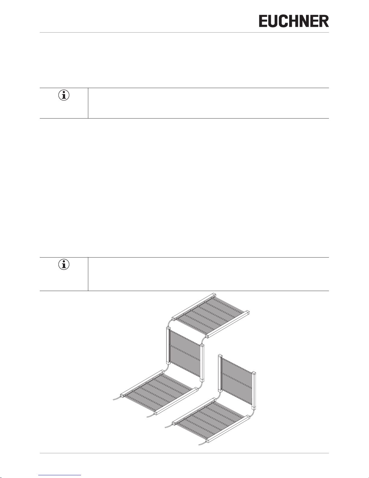
6.3. Master-Slave Funktion
Die Master-Slave Funktion ermöglicht die Reihenschaltung von bis zu drei Lichtvorhängen. Diese bestehen aus einer Master
und bis zu zwei Slave Einheiten.
Die Reihenschaltung ermöglicht eine Kombination von verschiedenen Schutzfunktionen wie Finger-, Hand- und Körperschutz.
Hierzu werden verschiedene LCA 4-Typen über Verbindungskabel verbunden.
Die Kombinationsmöglichkeiten sind im Bild 4 ersichtlich.
HINWEIS
Zur Verbindung von Master- / Slave Modulen können Verbindungskabel von einer Länge bis zu 50m
eingesetzt werden.
SLAVE 1
SLAVE 2
MASTER
MASTER
SLAVE 1
Bild 4: LCA Master- / Slave Module
Page 11

11
2504709-01-06/17 (Originalbetriebsanleitung)
Betriebsanleitung
Lichtgitter/ Lichtvorhänge LCA 4
DE
6.3.1. Beispielanwendung Hintertretschutz
Das Master-Gerät wird als primäre Schutzeinrichtung verwendet. Das Slave-Gerät dient als sekundäre Schutzeinrichtung.
Beim Betreten der Einrichtung werden die Lichtstrahlen des Lichtvorhangs unterbrochen und die Maschinenbewegung gestoppt.
Der horizontal installierte Lichtvorhang erkennt, dass sich eine Person im Gefahrenbereich befindet, weil die Lichtstrahlen
auch hier unterbrochen sind. Die Maschinenbewegung bleibt gestoppt.
Wenn die Person den Gefahrenbereich verlassen hat, wechseln die Geräte (Master/Slave) in den Normalbetrieb. Anschließend
kann die Maschine gestartet werden.
Bild 5: Hintertretschutz: Gefahrenbereich frei
Bild 6: Hintertretschutz: Gefahrenbereich belegt
6.3.2. Rückführkreis Anbindung
Der Rückführkreis ermöglicht die Funktionsüberwachung extern angeschlossener Relais oder Schütze.
Die Sicherheitsausgänge werden erst bei geschlossenem Rückführkreis eingeschaltet.
HINWEIS
Für weitere Informationen siehe Kapitel: Inbetriebnahme
Page 12
Betriebsanleitung
Lichtgitter/ Lichtvorhänge LCA 4
12
(Originalbetriebsanleitung) 2504709-01-06/17
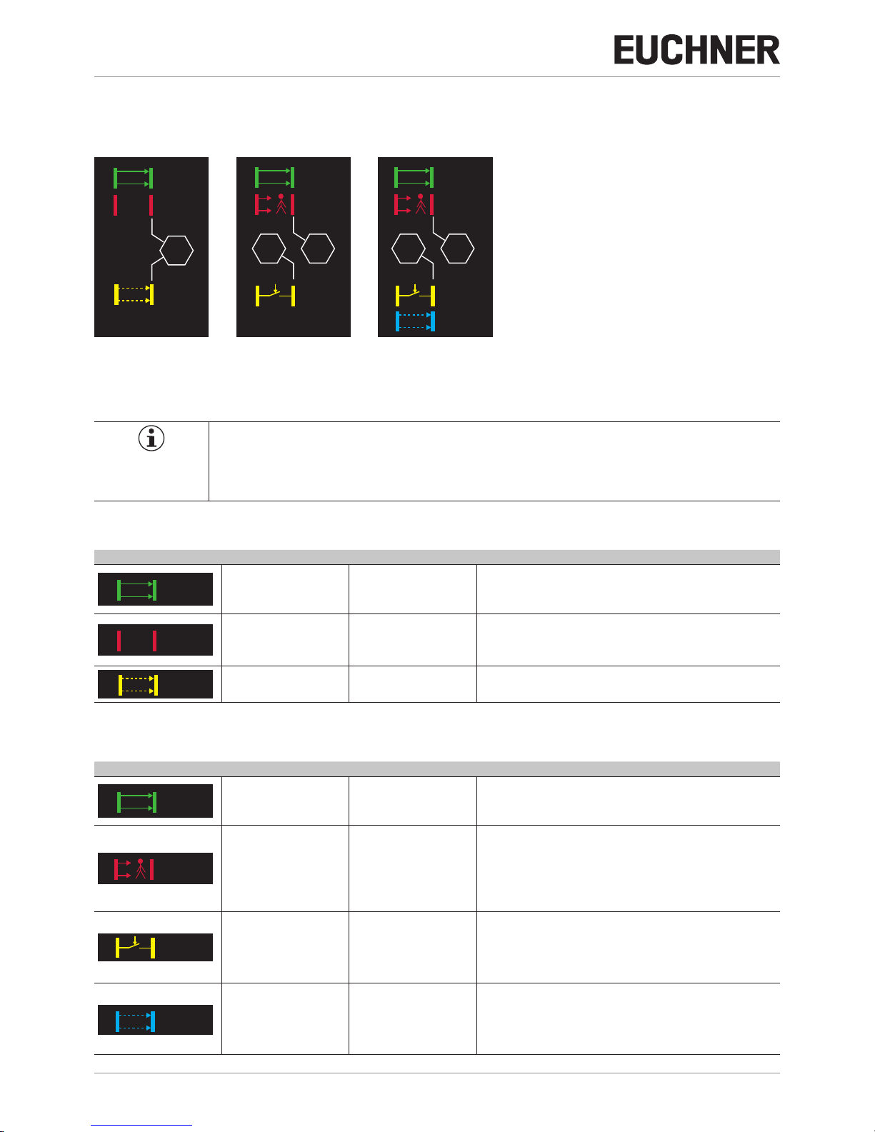
6.4. LED-Anzeigen
In den folgenden Abbildungen, werden die verschiedenen Systemzustände des Senders und des Empfängers dargestellt.
STOP
OK
SIGNAL
LOW
START
STOP
OK
START
?
ERROR
OK
TEST
Sender Empfänger Empfänger
(bei 14 mm Auflösung /
erhöhter Reichweite)
HINWEIS
Anhand der LED-Anzeigen ist der jeweilige Systemzustand des Geräts ersichtlich.
Zur Behebung fehlerhafter Systemzustände, siehe Kapitel Diagnose / Fehlerbehebung.
LED-Anzeigen SENDER
Abbildung Systemzustand LED-Anzeige Beschreibung
OK
Normalbetrieb
Power Up
Grün Der Sender ist im Normalbetrieb.
Die grüne LED leuchtet konstant.
Während des Einschalt-Vorgangs leuchtet die grüne LED zweimal kurz auf
Power-Up mit Auswahl: Reichweite Hoch.
?
ERROR
Fehler Rot blinkend
FO1A und FO1B sind inaktiv.
Die rote LED blinkt.
Das überwachte Gerät darf nicht betrieben werden.
Power Up Rot Während des Einschalt-Vorgangs leuchtet die rote LED. (2s)
TEST
Test-Funktion Orange
Die Test-Funktion des Senders ist aktiv.
Die LED leuchtet orange.
LED-Anzeigen EMPFÄNGER
Abbildung Systemzustand LED-Anzeige Beschreibung
OK
Normalbetrieb Grün
Der Empfänger ist im Normalbetrieb.
FO1A und FO1B sind aktiv.
Die grüne LED leuchtet konstant.
Das überwachte Gerät kann betrieben werden.
STOP
Stopp Rot
Mindestens ein Strahl wurde unterbrochen.
FO1A und FO1B sind inaktiv.
Die rote LED leuchtet konstant.
Das überwachte Gerät darf nicht betrieben werden.
Fehler Rot blinkend
FO1A und FO1B sind inaktiv. (Gerätefehler)
Die rote LED blinkt.
Das überwachte Gerät darf nicht betrieben werden.
START
Start-/ Neustart Gelb
Manueller Start- /Neustartmodus
FO1A und FO1B sind inaktiv.
Die gelbe LED leuchtet.
Das überwachte Gerät darf erst wieder betrieben werden, wenn der
Erfassungsbereich von allen Blockierungen befreit wurde und die
Start-Taste gedrückt und wieder losgelassen wurde.
SIGNAL
LOW
Schwaches Signal Blau
Schwache Signalstärke
Die blaue LED leuchtet.
Ursachen können zu einem schwachen Signal führen:
Falsche Ausrichtung zwischen Sender und Empfänger.
Schmutz auf der optischen Fläche
Störeinflüsse wie Nebel, Regen, Rauch oder Staub
Page 13

13
2504709-01-06/17 (Originalbetriebsanleitung)
Betriebsanleitung
Lichtgitter/ Lichtvorhänge LCA 4
DE
6.5. Sicherheitsausgänge
Die Empfängereinheit besitzt die zwei Sicherheitsausgänge F01A/FO1B (PNP-Ausgänge).
Die detaillierten Schaltzustände des Gerätes, finden Sie in der untenstehenden Tabelle.
Eventuelle Kurzschlüsse zwischen den Ausgängen und den Versorgungen von 24VDC oder 0VDC, werden vom Gerät
selbst erfasst.
Tabelle 3: Schaltzustände
Signalname Bedingungen Bedeutung
FO1A
24VDC Ì geschützter Bereich frei
FO1B
FO1A
0VDC
Ì Bedingung geschützter Bereich belegt / Defekt oder
Ì Defekt festgestellt
FO1B
Wichtig!
Unter der Bedingung geschützter Bereich frei, liefert der Empfänger eine Spannung von 24VDC an
beide Ausgänge. Die erforderliche Last muss somit zwischen den Sicherheitsausgängen und 0VDC
(siehe Bild 7) verbunden werden.
Zur Gewährleistung der Sicherheit müssen immer beide Sicherheitsausgänge (FO1A/FO1B) ausgewertet werden.
FO1A
FO1B
Max. Last
400 mA
E
0 V DC
LL
FO1A
FO1B
Max. Last
400 mA
E
24 V DC
LL
Bild 7: Anschluss der Last auf den Sicherheitsausgängen und 0VDC
Page 14
Betriebsanleitung
Lichtgitter/ Lichtvorhänge LCA 4
14
(Originalbetriebsanleitung) 2504709-01-06/17
7. Montage
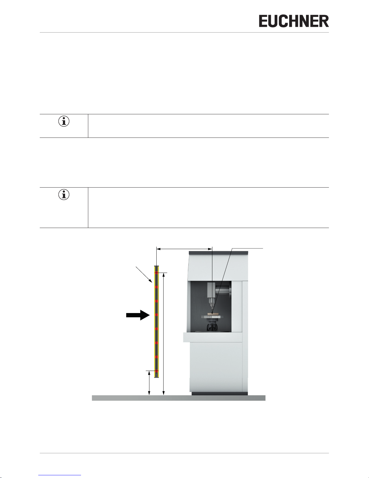
Sender und Empfänger müssen unter Einhaltung des Mindestsicherheitsabstands S positioniert werden. Das Erreichen des
Gefahrenbereichs darf nur nach dem Stoppen der gefahrbringenden Maschinenbewegung möglich sein (siehe Bild 8 ). Die
Berechnung des Sicherheitsabstands für Lichtgitter und Lichtvorhänge muss anhand der folgenden Kapitel erfolgen.
Bild 8: Sicherheitsabstand S
Der Mindestsicherheitsabstand S wird anhand der folgenden Formel berechnet:
S=K(t1+t2)+C
C=8(d–14)
Variable Denition
S
Mindestsicherheitsabstand [mm] ergibt sich aus der Entfernung zwischen
Beginn des Erfassungsbereichs und Beginn des Gefahrenbereichs
K
Annäherungsgeschwindigkeit des Körpers an den Gefahrenbereich [mm/s]
t1
Gesamtreaktionszeit der berührungslos wirkenden Schutzeinrichtung in Sekunden [s]
t2
Reaktionszeit der Maschine in Sekunden, Das ist die Zeit, welche die Maschine benötigt, um nach einem Stoppsignal den gefährlichen Vorgang zu unterbrechen [s]
C
Zusätzlicher Abstand, der je nach Anwendung variiert [mm]
1)
d
Auflösung [mm]
1) Für weitere Informationen hinsichtlich des zusätzlichen Abstands siehe EN 13855:2010
Wichtig!
Ì Der Mindestsicherheitsabstand muss eingehalten werden, da sonst die Schutzfunktion des Geräts
nicht gewährleistet ist.
Ì Sollte der Zugang zum Gefahrenbereich ohne eine Unterbrechung des Schutzfelds möglich sein,
ist zusätzlich eine trennende Schutzeinrichtung vorzusehen.
Page 15
15
2504709-01-06/17 (Originalbetriebsanleitung)
Betriebsanleitung
Lichtgitter/ Lichtvorhänge LCA 4
DE
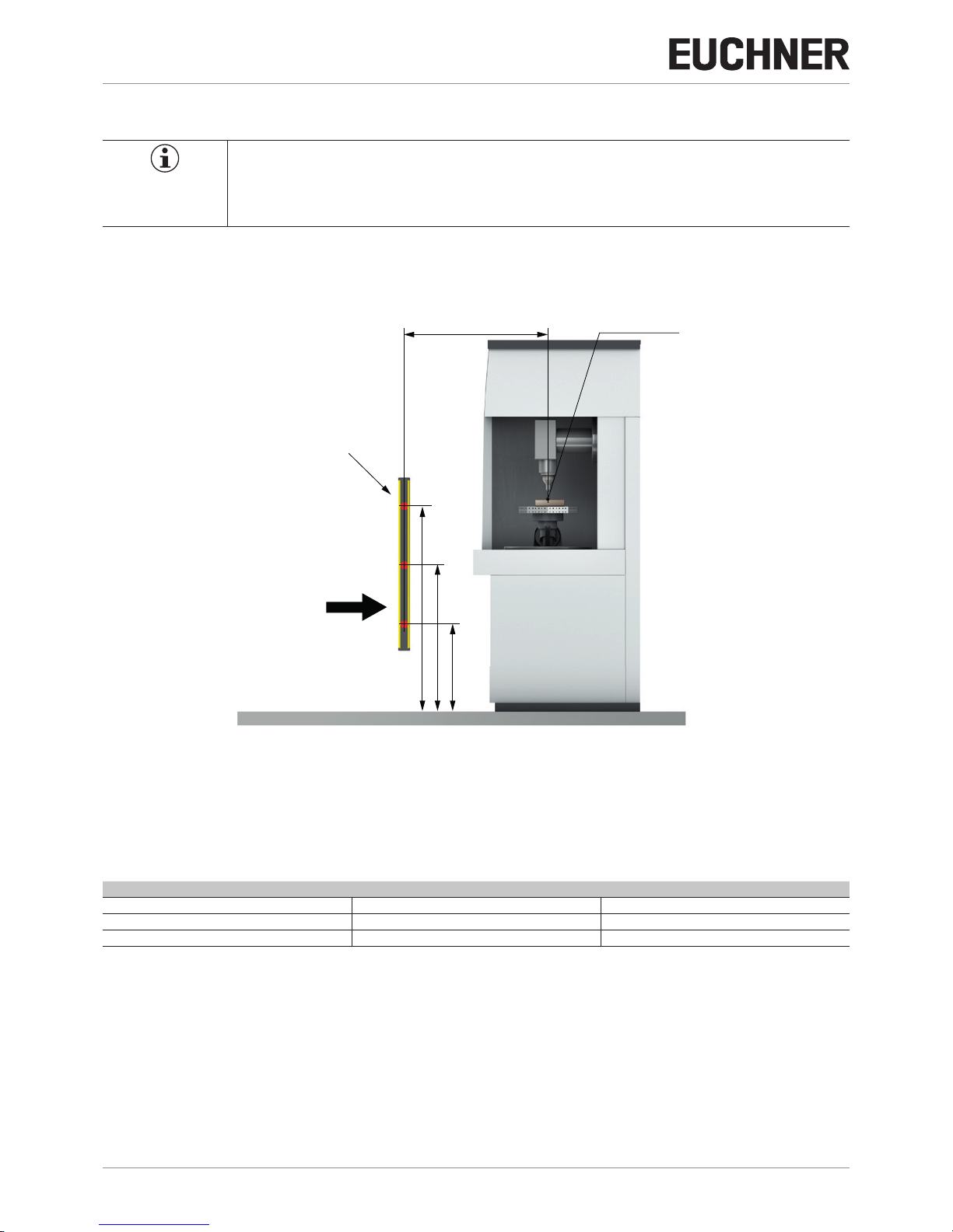
7.1. Sicherheitsabstand Lichtvorhänge (horizontale Montage)
Bei einer horizontalen Montage des Schutzfelds zur Annäherungsrichtung, wird der Mindestsicherheitsabstand S nach folgender Formel berechnet.
S=1600(t1+t2)+1200–0.4H
H=15(d–50)
HINWEIS
Die Höhe H ergibt sich aus dem Abstand der Schutzeinrichtung zur Grundfläche (G).
Wichtig!
Die Höhe H muss stets geringer als 1000mm sein.
Sollte die Höhe 300mm überschreiten, besteht die Gefahr der Umgehung des Schutzfelds.
Es sind zusätzliche Schutzmaßnahmen in Form einer trennenden Schutzeinrichtung erforderlich.
G
Bezugs-Boden (G)
S
Gefahrenstelle
Richtung der
Annäherung
Lichtvorhang
H
Bild 9: Horizontale Montage für Lichtvorhänge
Page 16
Betriebsanleitung
Lichtgitter/ Lichtvorhänge LCA 4
16
(Originalbetriebsanleitung) 2504709-01-06/17
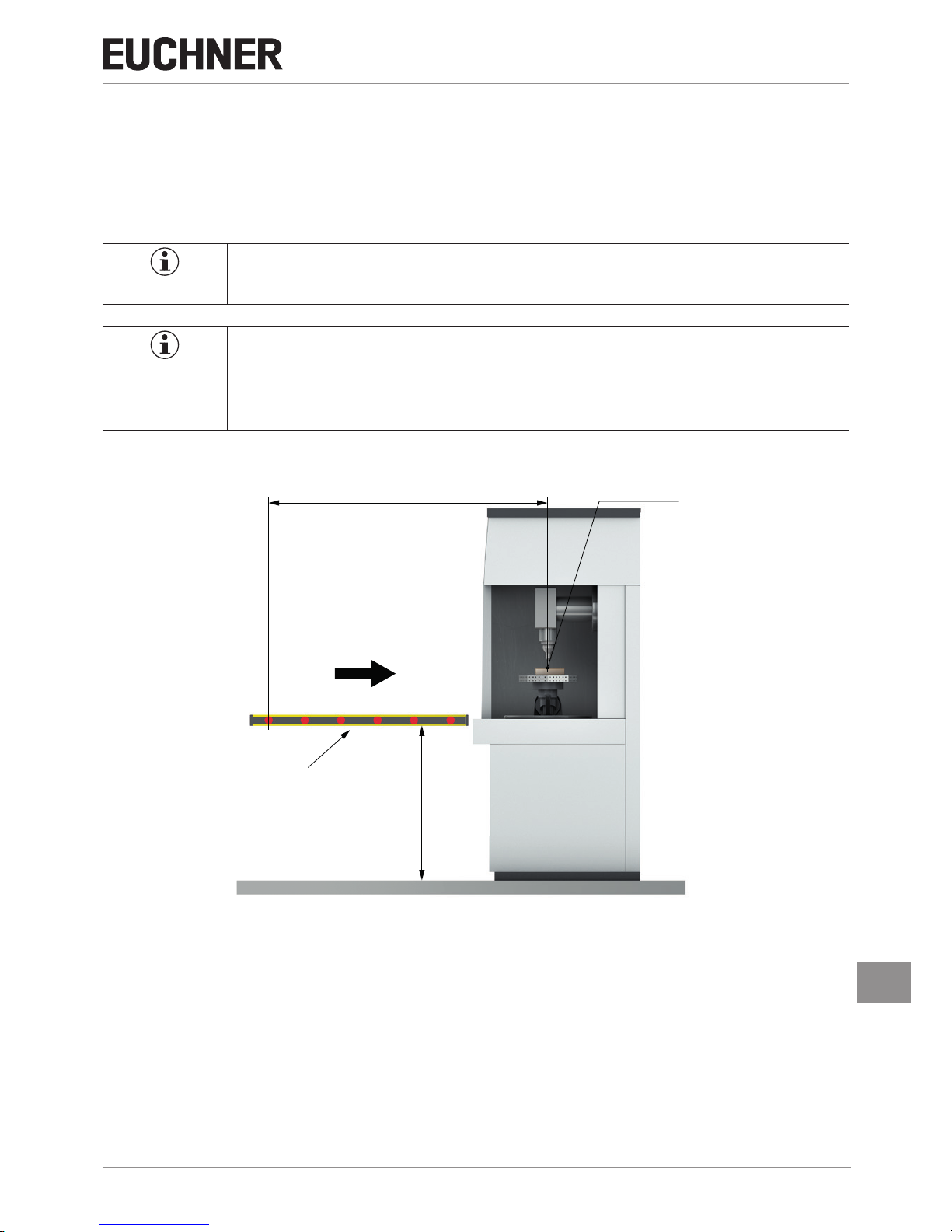
7.2. Sicherheitsabstand Lichtvorhänge (vertikale Montage)
Für die vertikale Montage ist zunächst die Auflösung des Geräts zu bestimmen.
Abhängig vom Ergebnis wird in zwei Fälle unterschieden:
Fall A: Auflösung ≥ 50mm
Fall B: Auflösung < 50mm
Je nach Ergebnis, ist der entsprechende Abschnitt zu beachten.
TIPP
Die Auflösung des Geräts finden Sie im Kapitel 11: Technische Daten
Fall A: Auösung ≥ 50mm
Der Sicherheitsabstand S wird mit folgender Formel berechnet:
S=1600(t1+t2)+850
Wichtig!
Folgende Abstände sind bei der Berechnung einzuhalten:
Ì Abstand Grundfläche (G) – erster Lichtstrahl = H1 max. 300 mm
Ì Abstand Grundfläche (G) – letzter Lichtstrahl = H2 min. 900 mm
G
Bezugs-Boden (G)
S
Gefahrenstelle
Richtung der
Annäherung
Lichtvorhang
H≥900
H≤300
Bild 10: Vertikale Montage für Lichtvorhänge mit Auflösung ab 50mm
Page 17

17
2504709-01-06/17 (Originalbetriebsanleitung)
Betriebsanleitung
Lichtgitter/ Lichtvorhänge LCA 4
DE
Fall B: Auösung ≤ 50mm
Wichtig!
Für eine Auflösung ≤50mm ist ein zusätzlicher Abstand zum Gefahrenbereich zu beachten!
Der Sicherheitsabstand S wird mit folgender Formel berechnet:
S=2000(t1+t2)+C
Wenn das Ergebnis der Berechnung sich im Wertebereich 100–500mm befindet, kann der Wert S verwendet werden.
Wenn sich aus der Berechnung ergibt, dass S größer als 500 mm ist, wird folgende Formel verwendet:
S=1600(t1+t2)+C
Wichtig!
Wenn das Erreichen des Gefahrenbereichs (z.B. durch Darübergreifen) möglich sein sollte, muss die
Höhe H anhand der EN ISO 13855 neu berechnet werden.
Eine Umgehung der Schutzeinrichtung darf unter keinen Umständen möglich sein.
G
Bezugs-Boden (G)
S
Gefahrenstelle
Richtung der
Annäherung
Lichtvorhang
H
Bild 11: Vertikale Montage für Lichtvorhänge mit Auflösung 14mm, 30mm, 40mm
Page 18
Betriebsanleitung
Lichtgitter/ Lichtvorhänge LCA 4
18
(Originalbetriebsanleitung) 2504709-01-06/17
7.3. Sicherheitsabstand Lichtgitter (vertikale Montage)
Wichtig!
Lichtgitter sind ausschließlich zum Erfassen des gesamten Körpers geeignet.
Für die Erfassung einzelner Körperteile sind Lichtvorhänge zu verwenden.
Der Sicherheitsabstand S wird mit folgender Formel berechnet:
S=1600(t1+t2)+850
G
Bezugs-Boden (G)
S
Gefahrenstelle
Richtung der
Annäherung
Lichtgitter
1100
700
300
Bild 12: Montage für Lichtgitter
Lichtgitter sind in den folgenden Schutzfeldhöhen erhältlich:
Tabelle 4: Übersicht Lichtgitter
Modell Strahlen Schutzfeldhöhe (mm)
LCA 4 2B 2 510
LCA 4 3B 3 810
LCA 4 4B 4 910
Page 19

19
2504709-01-06/17 (Originalbetriebsanleitung)
Betriebsanleitung
Lichtgitter/ Lichtvorhänge LCA 4
DE
7.4. Installation
Wichtig!
Vor dem Installieren des Sicherheitssystems müssen alle im Anschluss aufgeführten Bedingungen
überprüft werden:
Ì Der Schutzgrad (Typ 4, SIL3, SILCL3, PLe) des Systems, muss mit der Gefährlichkeit des zu steu-
ernden Systems vereinbar sein.
Ì Die Bedienung der Maschine muss über eine Steuerung realisiert sein
Ì Die Bedienung der Maschine muss elektrisch steuerbar sein.
Ì Es muss möglich sein, jeden gefährlichen Vorgang der Maschine umgehend zu stoppen. Insbeson-
dere muss die Dauer des Stoppvorgangs der Maschine bekannt sein.
Ì Die Maschine darf keine physischen Gefährdungen erzeugen (Herausschleudern von Teilen, Hitze,
Strahlung). In diesem Fall ist eine trennende Schutzeinrichtung vorzusehen.
Ì Die Mindestgröße des zu erfassenden Gegenstands muss der Auflösung des ausgewählten Mo-
dells entsprechen oder größer sein.
Ì Höhe und Breite des Gefahrenbereichs müssen vom Schutzfeld des jeweiligen Modells abgedeckt sein.
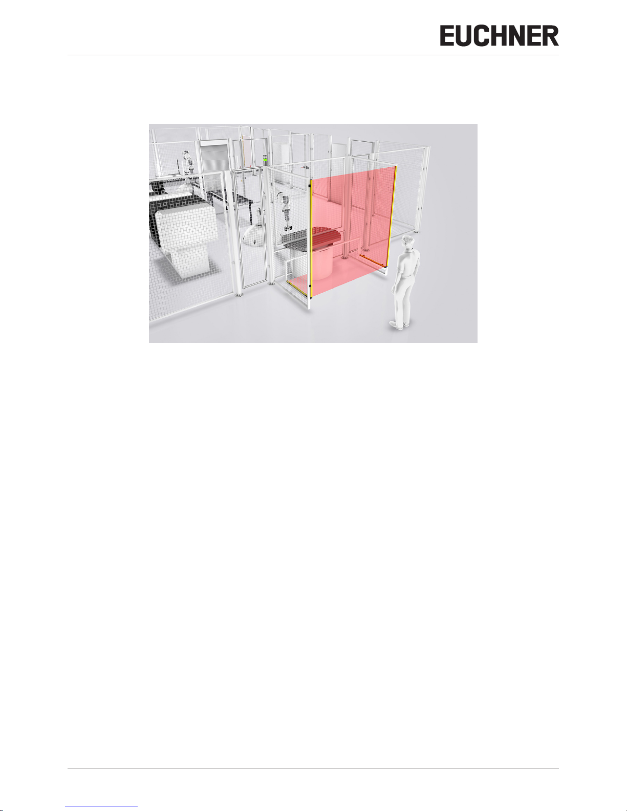
7.5. Positionierung
Wichtig!
Ì Prüfen Sie, ob die Raumtemperatur mit der Betriebstemperatur des Gerätes vereinbar ist
Ì Positionieren Sie Sender und Empfänger nicht in der Nähe von stark reflektierenden Lichtquellen.
Ì Bei Fremdlichteinwirkungen über 3000 lx kann es zu Funktionsstörungen kommen. Prüfen Sie ihre
Umgebungsbedingungen vor Einsatz des Systems.
Das Schutzfeld von Sender und Empfänger muss den Gefahrenbereich vollständig abdecken. Der Zugang zum Gefahrenbereich darf nur möglich sein, indem mind. ein Lichtstrahl eines Lichtgitters oder eines Lichtvorhangs unterbrochen wird.
Die folgende Grafik zeigt einige Montagebeispiele für eine korrekte Positionierung der Geräte.
Bild 13: Positionierung der Schutzeinrichtung
Page 20
Betriebsanleitung
Lichtgitter/ Lichtvorhänge LCA 4
20
(Originalbetriebsanleitung) 2504709-01-06/17
7.6. Nutzbare Reichweite bei besonderen Umgebungsbedingungen
Bei Umgebungsbedingungen in denen Nebel, Regen, Rauch oder Staub auftritt, sind Korrekturen in der Reichweite vorzunehmen. Diese können der folgenden Tabelle entnommen werden.
Tabelle 5: Korrekturfaktor Fc
Umgebungsbedingungen Korrekturfaktor Fc
Nebel 0,25
Dämpfe 0,50
Staub 0,50
Dichter Rauch 0,25
Anhand der folgenden Formel, kann die Korrektur berechnet werden.
Pu = Pm x Fc
Tabelle 6: Berechnung Korrekturfaktor Fc
Kürzel Denition
Pu nutzbare Reichweite
Pm maximale Reichweite in Metern
Fc Korrekturfaktor
ACHTUNG!
Verlust der Sicherheitsfunktion durch Kondenswasserbildung
Kondenswasser kann die Schutzfunktion des Geräts außer Kraft setzen
Vermeiden Sie plötzliche Temperaturschwankungen am Einsatzort
Reinigen Sie ihr System regelmäßig.
7.7. Einsatz von mehreren Schutzeinrichtungen (Multiple Systeme)
WARNUNG
Fehlfunktion, Verlust der Sicherheitsfunktion durch optische Störeinflüsse
Durch fehlerhafte Positionierung können Lichtstrahlen eines anderen Senders empfangen werden.
Sender und Empfänger müssen so positioniert werden, dass die ausgesendeten Strahlen eines
Senders, nur vom jeweiligen Empfänger empfangen werden können.
Bei Einsatz mehrerer Systeme ist darauf zu achten, dass sich Sender und Empfänger nicht in ihrer Funktion beeinträchtigen.
Die folgenden Positionierungsbeispiele können verwendet werden:
Nr. Beschreibung
A Positionierung von zwei Systemen nebeneinander
B Positionierung von zwei Systemen übereinander
C Positionierung von zwei Systemen in L-Form
Page 21

21
2504709-01-06/17 (Originalbetriebsanleitung)
Betriebsanleitung
Lichtgitter/ Lichtvorhänge LCA 4
DE
S
S2
E
E1
C
S
S1
E
E1
S
S2
E
E2
B
E
E1
S
S1
E
E2
S
S2
A
Bild 14: Einsatz von mehreren Schutzeinrichtungen (Multiple Systeme)
Page 22
Betriebsanleitung
Lichtgitter/ Lichtvorhänge LCA 4
22
(Originalbetriebsanleitung) 2504709-01-06/17
7.8. Positionierung Master/Slave
Die Master / Slave Funktion ermöglicht eine mehrseitige Überwachung eines Gefahrenbereichs. Es ist nur ein Anschluss zu
den Versorgungs- und Steuerkreisen notwendig.
Bild 15: Positionierungsbeispiel Master/Slave
Page 23

23
2504709-01-06/17 (Originalbetriebsanleitung)
Betriebsanleitung
Lichtgitter/ Lichtvorhänge LCA 4
DE
7.9. Montieren und Ausrichten
Sender und Empfänger können über die optional erhältlichen Montagehalterungen montiert werden.
Bild 16: Mechanische Montage
Folgende Punkte sind bei der Montage des Systems zu beachten:
Montieren Sie Sender und Empfänger auf einem planen Untergrund.
Die optischen Flächen müssen genau aufeinander ausgerichtet sein.
Sender und Empfänger müssen auf einer Höhe installiert werden. Nutzen Sie die LEDs für die korrekte Ausrichtung von
Sender und Empfänger. Bei korrekter Ausrichtung leuchtet die LED am Empfänger konstant grün.
Beachten Sie das maximale Anzugsdrehmoment für die Befestigung der Montagehalterungen von 5 bis 6Nm.
Beachten Sie das maximale Anzugsdrehmoment für die Befestigung von Sender und Empfänger an der Montagehalterung
von 2,5 bis 3Nm.
Verwenden Sie für die Montage ausschließlich Zubehörteile von EUCHNER.
GEFAHR
Außerkraftsetzen der Sicherheitsfunktion
Bei falscher Montage, kann die Schutzfunktion des Systems außer Kraft gesetzt werden.
Montieren Sie Sender und Empfänger immer unter Beachtung des Mindestabstands S.
Achten Sie darauf, dass ein Übergreifen, Untergreifen, Umgehen, Hintertreten, sowie ein Verschieben
des Systems ausgeschlossen sind.
Stellen Sie sicher, dass der Gefahrenbereich durch das Schutzfeld des Systems ausreichend
geschützt ist.
HINWEIS
Geräteschäden und Funktionsstörungen durch falschen Einbau
Achten Sie bei der Montage des Systems darauf, die Komponenten nicht zu beschädigen.
Beachten Sie das maximale Anzugsdrehmoment.
Page 24

Betriebsanleitung
Lichtgitter/ Lichtvorhänge LCA 4
24
(Originalbetriebsanleitung) 2504709-01-06/17
7.10. Optische Ausrichtung
S E
E
S
S
E
S
E
STOP
OK
SIGNAL
LOW
START
STOP
OK
SIGNAL
LOW
START
gn
rd
Bild 17: Optische Ausrichtung Sender und Empfänger
Page 25
25
2504709-01-06/17 (Originalbetriebsanleitung)
Betriebsanleitung
Lichtgitter/ Lichtvorhänge LCA 4
DE
Tipp!
Für die nachfolgende Ausrichtung von Sender und Empfänger, empfehlen wir die Verwendung der
Ausrichthilfe vom Typ AY-OS-LSR.
1. Richten Sie Sender und Empfänger so aus, dass sich der jeweils erste und letzte Lichtstrahl auf derselben Achse befinden.
2. Bewegen Sie Sender und Empfänger solange, bis die grüne LED auf dem Empfänger konstant leuchtet.
Modelle 14 mm und erhöhte Reichweite:
1. Nutzen Sie die blaue LED, um die Signalstärke zu kontrollieren.
2. Wenn die blaue LED konstant leuchtet, liegt ein schwaches Signal vor.
3. Kontrollieren Sie Sender und Empfänger auf Störeinflüsse und Verschmutzungen.
4. Überprüfen Sie erneut die Ausrichtung beider Komponenten bis die blaue LED erlischt.
HINWEIS
Zur weiteren Fehlerbehebung siehe Kapitel LED-Anzeigen und Kapitel Diagnose / Fehlerbehebung
3. Fixieren Sie Sender und Empfänger in der momentanen Position.
Wichtig!
Beachten Sie das maximale Anzugsdrehmoment für die Befestigung von Sender und Empfänger an
der Montagehalterung von 2,5 bis 3Nm.
Wichtig!
Sind Sender und Empfänger in Bereichen montiert, die starken Erschütterungen ausgesetzt sind, ist
die Verwendung von vibrationshemmenden Trägern erforderlich
7.11. Verwendung von Umlenkspiegeln
Umlenkspiegel ermöglichen eine Vergrößerung des Schutzfelds. Die vom Sender erzeugten Lichtstrahlen können auf mehrere Seiten umgelenkt werden. Das folgende Bild zeigt eine Anwendung, bei der zwei Umlenkspiegel verwendet werden, um
einen U-förmigen Schutz zu erzielen.
GEFAHR
Außerkraftsetzen der Sicherheitsfunktion durch Beeinträchtigungen am Spiegel.
Verschmutzte oder beschädigte Bereiche am Umlenkspiegel können die Sicherheitsfunktion außer
Kraft setzen.
Verwenden Sie keine Umlenkspiegel, wenn mit Verschmutzungen, Kondenswasserbildung oder Reif
am Einsatzort zu rechnen ist.
Reinigen Sie die Umlenkspiegel regelmäßig, um Verschmutzungen und Beschädigungen zu ver-
meiden.
Page 26

Betriebsanleitung
Lichtgitter/ Lichtvorhänge LCA 4
26
(Originalbetriebsanleitung) 2504709-01-06/17
Gefahrenbereich
L1
L2
L3
S
S
S
Sender
Empfänger
Spie
gel
Spiege
l
Bild 18: Verwendung von Umlenkspiegeln
1. Ermitteln Sie den Arbeitsabstand über die Summen der Längen des geschützten Bereichs.
(L1 = Sender – Spiegel, L2 = Spiegel – Spiegel , L3 = Spiegel – Empfänger)
Beachten Sie, dass sich bei Einsatz eines Spiegels, die max. Reichweite zwischen Sender und Empfänger mit jedem
verwendeten Spiegel um jeweils 15% reduziert.
HINWEIS
Bei der Berechnung der Reichweite, muss je Spiegel vom jeweils verminderten Wert ausgegangen
werden.
Anhand der folgenden Formel kann die Reichweite berechnet werden:
Eff. Reichweite R
eff
=R
max˙
0,85
n
Variable Denition
R
eff
effektive Reichweite
R
max
max. Reichweite des Geräts
n Anzahl der Spiegel
Wichtig!
Die Signalerkennung kann über die LED-Anzeige überprüft werden.
Siehe Kapitel: LED-Anzeigen
2. Positionieren Sie die Spiegel unter Beachtung des Arbeitsabstands und des Mindestsicherheitsabstands S um den Gefahrenbereich.
Achten Sie darauf, keine Verzerrungen entlang der Längsachse zu erzeugen
Tipp!
Es wird empfohlen nicht mehr als drei Umlenkspiegel zu verwenden.
Page 27
27
2504709-01-06/17 (Originalbetriebsanleitung)
Betriebsanleitung
Lichtgitter/ Lichtvorhänge LCA 4
DE
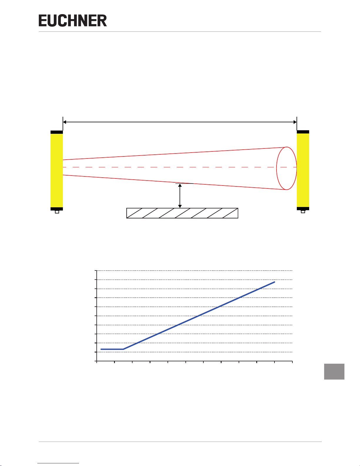
7.12. Abstand von reektierenden Flächen
Reflektierende Oberflächen in der Nähe des Geräts können die Erfassung des Lichtstrahls beeinflussen. Mit zunehmender
Entfernung zwischen Sender und Empfänger, vergrößert sich der Lichtkegel eines Lichtstrahls. Dieser kann von reflektierenden Objekten abgelenkt werden und wieder an den Empfänger gesendet werden. Eine Unterbrechung des Schutzfeldes,
hätte unter Umständen keine Auswirkung auf die Sicherheitsausgänge. Die Schutzfunktion des LCA-Systems ist somit nicht
mehr gewährleistet.
Es muss daher ein Mindestabstand d zwischen eventuell reflektierenden Oberflächen und dem geschützten Bereich
eingehalten werden.
d
L
S
E
Bild 19: Mindestabstand d zu reflektierenden Objekten
Der Mindestabstand d kann anhand des folgenden Diagramms abgelesen werden.
Alternativ kann dieser anhand der Norm EN 61496-2 berechnet werden.
0
100
200
300
400
500
600
700
800
900
1000
0246810 12 14 16 18 20 22
Mindestabstand d (mm)
Nutzbare Reichweite (m)
Page 28
Betriebsanleitung
Lichtgitter/ Lichtvorhänge LCA 4
28
(Originalbetriebsanleitung) 2504709-01-06/17
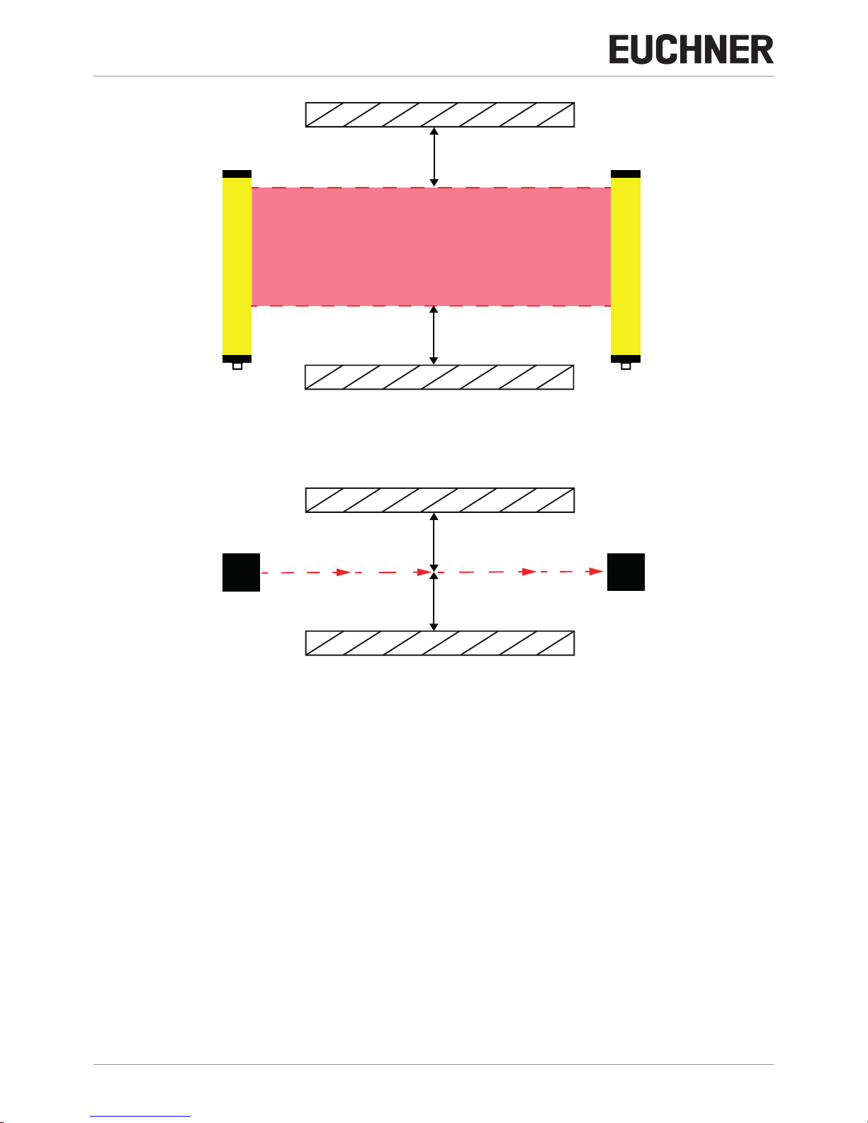
S E
d
d
Schutzfeld
d
d
SE
Bild 20: Mindestabstand d / Nutzbare Reichweite
Page 29

29
2504709-01-06/17 (Originalbetriebsanleitung)
Betriebsanleitung
Lichtgitter/ Lichtvorhänge LCA 4
DE
8. Elektrischer Anschluss
VORSICHT
Geräteschäden oder Fehlfunktion durch falschen Anschluss
Ì Vergewissern Sie sich vor der Herstellung der elektrischen Anschlüsse, dass die verfügbare Ver-
sorgungsspannung mit der in den technischen Daten angegebenen übereinstimmt.
Ì Sender und Empfänger müssen mit einer Spannung von 24 V DC ± 20 % versorgt werden (PELV,
muss EN 60204-1 (Kapitel 6.4) entsprechen).
Ì Die elektrischen Anschlüsse müssen unter Einhaltung der Schaltpläne dieser Bedienungsanleitung
gelegt werden. Es dürfen keine weiteren Geräte an die Steckverbinder von Sender und Empfänger
angeschlossen werden.
Ì Bei Verwendung eines Netzteils mit Diodenbrücke, muss die Ausgangskapazität
mindestens 2000 μF für jedes aufgenommene Ampere betragen.
Ì Leitungsgeräte, die eine starke Störquelle darstellen, müssen von den Ein-/ und Ausgangskreisen
für die Signalverarbeitung örtlich getrennt werden. Die Leitungseinführung der Sicherheitskreise
sollte möglichst weit von den Leitungen der Leistungskreise getrennt werden.
Ì Die Funktionserde muss angeschlossen werden, um den EMV Anforderungen zu entsprechen.
Ì Zur Vermeidung von EMV-Störungen müssen physikalische Umgebungs- und Betriebsbedingungen
am Einbauort des Gerätes den Anforderungen gemäß EN 60204-1:2006, Abschnitt 4.4.2 (EMV)
entsprechen.
WARNUNG
Zur Gewährleistung der Sicherheit müssen immer beide Sicherheitsausgänge ausgewertet werden.
8.1. Senderanschlüsse
8.1.1. LCA 4 (Mit Integrierten Steuerfunktionen) – LCA 4 Master Primärverbinder M12, 5-polig
Tabelle 7: M12, 5-polig - Master/Standard/mit integrierten Steuerfunktionen TX
Pin Farbe Name Typ Beschreibung
1 Braun 24VDC
INPUT
Versorgung 24VDC
2 Weiß RANGE0
Gerätekonfiguration
Entspricht der Norm EN61131-2
(siehe Tabelle 8)
3 Blau 0VDC Versorgung 0VDC
4 Schwarz RANGE1
Gerätekonfiguration
Entspricht der Norm EN61131-2
(siehe Tabelle 8)
5 Grau FE Erdanschluss
Tabelle 8: Auswahl Reichweite und TEST
Auswahl Reichweite und Test - (Primärverbinder, 5-polig)
Pin 4 Pin 2 Bedeutung
24V 0V Auswahl Reichweite HOCH
0V 24V Auswahl Reichweite NIEDRIG
0V 0V Sender in TEST
24V 24V Auswahlfehler
HINWEIS
Für eine korrekte Betriebsart des Gerätes müssen die Pins 2 und 4 des Senders gemäß der Angaben
in der Tabelle 8 angeschlossen werden.
Page 30

Betriebsanleitung
Lichtgitter/ Lichtvorhänge LCA 4
30
(Originalbetriebsanleitung) 2504709-01-06/17
8.1.2. LCA 4 Slave 1 / LCA 4 Slave 2 – Primärverbinder M12, 5-polig
Tabelle 9: M12, 5-polig Primär Slave TX
Pin Farbe Name Beschreibung
1 Braun 24VDC Versorgung 24VDC
2 Weiß LINE_A Kommunikation MASTER-SLAVE
3 Blau 0VDC Versorgung 0VDC
4 Schwarz LINE_B Kommunikation MASTER-SLAVE
5 Grau FE Erdanschluss
8.1.3. LCA 4 Master – Sekundärverbinder M12, 5-polig
LCA 4 Slave 2 – Sekundärverbinder M12, 5-polig
Tabelle 10: M12, 5-polig Sekundär TX
Pin Farbe Name Beschreibung
1 Braun 24VDC Versorgung 24VDC
2 Weiß LINE_A Kommunikation MASTER-SLAVE
3 Blau 0VDC Versorgung 0VDC
4 Schwarz LINE_B Kommunikation MASTER-SLAVE
5 Grau FE Erdanschluss
8.2. Empfängeranschlüsse
8.2.1. LCA 4 (Modelle mit integrierten Steuerfunktionen) – Verbinder M12, 8-polig
LCA 4 Master – Primärverbinder M12, 8-polig
Tabelle 11: M12, 8-polig RX
Pin Farbe Name Typ Beschreibung Betriebsart
1 Weiß FO1A OUT Sicherheitsausgang 1 Aktiver PNP oben
2 Braun 24VDC - Versorgung 24VDC -
3 Grün FO1B OUT Sicherheitsausgang 2 Aktiver PNP oben
4 Gelb
K1_K2/
RESTART
INPUT Feedback externe Schützen
Entspricht der Norm EN 61131-2
(Bez. Abs. „Konfiguration und Be-
triebsarten“ Seite 32 )
5 Grau SEL_A INPUT
Gerätekonfiguration
6 Rosa SEL_B INPUT
7 Blau 0VDC - Versorgung 0VDC -
8 Rot FE - Erdanschluss -
8.2.2. LCA 4 Slave 1 / LCA 4 Slave 2 – Primärverbinder M12, 5-polig
Tabelle 12: M12, 5-polig Primär Slave RX
Pin Farbe Name Beschreibung
1 Braun 24VDC Versorgung 24VDC
2 Weiß LINE_A Kommunikation MASTER-SLAVE
3 Blau 0VDC Versorgung 0VDC
4 Schwarz LINE_B Kommunikation MASTER-SLAVE
5 Grau FE Erdanschluss
Page 31

31
2504709-01-06/17 (Originalbetriebsanleitung)
Betriebsanleitung
Lichtgitter/ Lichtvorhänge LCA 4
DE
8.2.3. LCA 4 Master – Sekundärverbinder M12, 5-polig
LCA 4 Slave 2 – Sekundärverbinder M12, 5-polig
Tabelle 13: M12, 5-polig Sekundär RX
Pin Farbe Name Beschreibung
1 Braun 24VDC Versorgung 24VDC
2 Weiß LINE_A Kommunikation MASTER-SLAVE
3 Blau 0VDC Versorgung 0VDC
4 Schwarz LINE_B Kommunikation MASTER-SLAVE
5 Grau FE Erdanschluss
VORSICHT
Geräteschäden oder Fehlfunktion durch ungeeignete Anschlussleitungen
Ì Verwenden Sie die Anschlussbauteile von EUCHNER.
Ì Bei Verwendung von Kabeln mit einer Länge über 50m, ist ein Querschnitt von mind. 1mm
2
zu
verwenden.
Page 32

Betriebsanleitung
Lichtgitter/ Lichtvorhänge LCA 4
32
(Originalbetriebsanleitung) 2504709-01-06/17
9. Betriebsarten/ Inbetriebnahme
9.1. Konguration und Betriebsarten (Modelle Master/mit integrierten Steuerfunktionen)
Die Betriebsart ist abhängig von den Ergebnissen der Risikoanalyse. Anhand des erforderlichen Schutzgrades, kann das
System für den automatischen oder manuellen Betrieb konfiguriert werden.
Die Funktionsweise des Gerätes kann über die Ansteuerung der Pins definiert werden. Die folgende Tabelle zeigt, wie diese
angesteuert werden können.
Tabelle 14: Betriebsart manuell / automatisch
Anschlüsse Betriebsart
K1_K2/restart (PIN 4)
Anschluss an: 24VDC
SEL_A (PIN 5)
Anschluss an: 24VDC
SEL_B (PIN 6)
Anschluss an: 0VDC
AUTOMATISCH
(Bild 22)
K1_K2/restart (PIN 4)
Anschluss an: 24VDC
(über Reihe Ruhekontakte von K1K2)
SEL_A (PIN 5)
Anschluss an: 24VDC
SEL_B (PIN 6)
Anschluss an: 0VDC
AUTOMATISCH
mit Steuerung K1K2
(Bild 22)
K1_K2/restart (PIN 4)
Anschluss an: 24VDC
(über RESTART-Taste)
SEL_A (PIN 5)
Anschluss an: 0VDC
SEL_B (PIN 6)
Anschluss an: 24VDC
MANUELL
(Bild 23)
K1_K2/restart (PIN 4)
Anschluss an: 24VDC
(über RESTART-Taste und
Reihe Ruhekontakte von K1K2)
SEL_A (PIN 5)
Anschluss an: 0VDC
SEL_B (PIN 6)
Anschluss an: 24VDC
MANUELL
mit Steuerung K1K2
(Bild 23)
9.1.1. Betriebsart Manuell
Die Sicherheitsausgänge FO1A und FO1B reagieren auf den Status des Gerätes. Werden die Lichtstrahlen unterbrochen,
schalten die Sicherheitsausgänge ab. Die Maschinenbewegung wird gestoppt.
Wenn der geschützte Bereich freigegeben ist, muss der Neustart manuell eingeleitet werden. Der Wiederanlauf der Maschine,
muss über einen Taster oder einem Befehl auf dem Eingang K1/K2 Restart manuell bestätigt werden.
GEFAHR
Schwere Verletzungen oder Tod durch Wiederanlauf der Maschine.
Ì Bei Unterbrechung schaltet die Schutzeinrichtung die Maschine ab.
Im jetzigen Zustand kann der Gefahrenbereich ohne Erfassung betreten werden.
(Einsatz als trip device gemäß EN 61496)
Stellen Sie vor dem manuellen Wiedereinschalten sicher, dass sich keine Personen im Gefahren-
bereich befinden.
9.1.2. Betriebsart Automatik
Wichtig!
Diese Betriebsart darf nur in Sonderfällen verwendet werden.
Ì Die Sicherheitsausgänge FO1A und FO1B reagieren auf den Status des Gerätes. Werden die Licht-
strahlen unterbrochen, schalten die Sicherheitsausgänge ab. Die Maschinenbewegung wird gestoppt.
Ì Wird der geschützte Bereich freigegeben, werden die Sicherheitsausgänge automatisch aktiviert
und der Normalbetrieb hergestellt (nach 2 Sekunden). Die Maschine läuft automatisch an.
GEFAHR
Schwere Verletzungen oder Tod durch Wiederanlauf der Maschine.
Ì Bei Unterbrechung des geschützten Bereichs, schalten die Sicherheitsausgänge ab. Bei Freigabe
des geschützten Bereichs, werden die Sicherheitsausgänge aktiviert. Der Wiederanlauf der Maschine erfolgt automatisch.
Stellen Sie sicher, dass die Betriebsart Automatik mit der erforderlichen Sicherheitsstufe der Risi-
koanalyse übereinstimmt und diese verwendet werden darf.
Page 33

33
2504709-01-06/17 (Originalbetriebsanleitung)
Betriebsanleitung
Lichtgitter/ Lichtvorhänge LCA 4
DE
VORSICHT
In der Betriebsart Automatik steht nach einem Neustart kein Verblockungskreis zur Verfügung.
(Start / Restart Interlock).
Beachten Sie vor einer Konfiguration das Ergebnis ihrer Risikoanalyse.
Tabelle 15: Betriebsart Automatik
Status Schutzeinrichtung Verhalten Sicherheitsausgänge
Bereich frei FO1A / FO1B aktiviert
Bereich unterbrochen FO1A / FO1B deaktiviert
9.1.3. Anschluss externe Schütze K1 und K2
Der Anschluss externer Schütze (K1/K2) ist in beiden Betriebsarten über eine Kontaktreihe möglich. Dazu muss der Steckverbinder am Empfänger mit den Ruhekontakten der externen Schütze verbunden werden.
Z Verbinden Sie PIN4 des 8-poligen M12 Steckverbinders über die Spannungsversorgung (24 V DC) mit den Ruhekontakten
der externen Schütze.
Wichtig!
In der Betriebsart Manuell muss sichergestellt sein, dass die Restart-Taste mit den Ruhekontakten der
externen Schütze K1/K2 verbunden sind.
Wenn notwendig, muss die Ansprechzeit der externen Schütze durch ein zusätzliches Gerät überprüft
werden.
9.1.4. Anschlussbeispiele mit Sicherheitsmodulen
24 V DC
GND
24 V DC
GND
LOW RANGE
HIGH RANGE
Range and TEST
selection
-B1
0V
DC
3
FE
5
RANGE0
2
RANGE1
4
+24V
DC
1
LCA
Range and TEST
selection
-B1
0V
DC
3
FE
5
RANGE0
2
RANGE1
4
+24V
DC
1
LCA
Bild 21: Sender
Page 34

Betriebsanleitung
Lichtgitter/ Lichtvorhänge LCA 4
34
(Originalbetriebsanleitung) 2504709-01-06/17
FO1B
3
K1_K2
RESTART
4
Operation mode
Safety
Outputs
SEL_A
5
SEL_B
6
+24V
DC
2
FE
8
0V
DC
7
FO1A
1
LCA
Connected
load
24 V DC
GND
A
UTOMATIC
FO1B
3
K1_K2
RESTART
4
Operation mode
Safety
Outputs
SEL_A
5
SEL_B
6
+24V
DC
2
FE
8
0V
DC
7
FO1A
1
LCA
Connected
load
24 V DC
GND
A
UTOMATIC WITH FEEDBACK
K2
K1
Bild 22: Empfänger Betriebsart Automatik
Page 35

35
2504709-01-06/17 (Originalbetriebsanleitung)
Betriebsanleitung
Lichtgitter/ Lichtvorhänge LCA 4
DE
FO1B
3
K1_K2
RESTART
4
Operation mode
Safety
Outputs
SEL_A
5
SEL_B
6
+24V
DC
2
FE
8
0V
DC
7
FO1A
1
LCA
Connected
load
MANUAL MODE
24 V DC
GND
FO1B
3
K1_K2
RESTART
4
Operation mode
Safety
Outputs
SEL_A
5
SEL_B
6
+24V
DC
2
FE
8
0V
DC
7
FO1A
1
LCA
Connected
load
MANUAL MODE WITH FEEDBACK
24 V DC
GND
RESTART
RESTART
K2
K1
Bild 23: Empfänger Betriebsart Manuell
Page 36

Betriebsanleitung
Lichtgitter/ Lichtvorhänge LCA 4
36
(Originalbetriebsanleitung) 2504709-01-06/17
Auxiliary
Contact
Start
0V
A2
UB
A1
Safety
Contacts
AC
AC
LOGIC
-K5
S21S11
ESM
13 33
14 34
23
24
S14
S12
S13S10
41
42
FO1B
3
K1_K2
RESTART
4
Operation mode
Safety
Outputs
SEL_A
5
SEL_B
6
+24V
DC
2
FE
8
0V
DC
7
FO1A
1
LCA
24 V DC
GND
Bild 24: Empfänger ESM Anschlussplan
Page 37

37
2504709-01-06/17 (Originalbetriebsanleitung)
Betriebsanleitung
Lichtgitter/ Lichtvorhänge LCA 4
DE
Safety Outputs Monitoring Outputs
Test Outputs
Digital Inputs
INPUT8
24
Feedback LoopMaster Enable
Power
Supply
0VDC
4
OSSD1_B
6
OUT_STAT2
12
OUT_STAT1
8
OUT_TEST1
13
OUT_TEST2
14
OUT_TEST3
15
OUT_TEST4
16
OSSD1_A
5
OSSD2_B
10
OSSD2_A
9
MAST_EN1
2
MAST_EN2
3
REST_FBK2
11
24VDC
1
REST_FBK1
7
-B2
INPUT1
17
INPUT2
18
INPUT3
19
INPUT4
20
INPUT5
21
INPUT6
22
INPUT7
23
MSC
FO1B
3
K1_K2
RESTART
4
Operation mode
Safety
Outputs
SEL_A
5
SEL_B
6
+24V
DC
2
FE
8
0V
DC
7
FO1A
1
LCA
24 V DC
GND
Connected
load
Bild 25: Empfänger MSC Anschlussplan
Page 38

Betriebsanleitung
Lichtgitter/ Lichtvorhänge LCA 4
38
(Originalbetriebsanleitung) 2504709-01-06/17
10. Diagnose/ Fehlerbehebung
Das Kapitel LED-Anzeigen gibt Aufschluss über verschiedene Systemzustände. Anhand der unten aufgeführten Tabelle können
diese erkannt und behoben werden.
Tabelle 16: Defektdiagnose Sender
Bedeutung
Dreifarbige LED
(Rot/Grün/Orange)
Blinkfolge Lösung
Fehlerhafter Anschluss der Pins 2 und 4 Rot 2 aufeinander folgende Impulse Ì Die Anschlüsse Pin 2 und 4 überprüfen.
Interner Fehler Rot 3/4 aufeinander folgende Impulse Ì Setzen Sie sich mit dem Hersteller in Verbindung.
Master und Slave nicht kompatibel Rot 5 aufeinander folgende Impulse Ì Kompatibilität der Modelle kontrollieren.
Wartezeit Kommunikation Master/Slave
1)
Orange Blinkend
Ì Den Zustand des Masters kontrollieren.
Ì Befindet er sich im Fehlerzustand, den Fehler überprüfen.
Ì Bleibt der Fehler bestehen, das Gerät zur Reparatur an den
Hersteller senden.
Verlust Kommunikation Master/Slave
2)
Orange 2 aufeinander folgende Impulse
Ì Anschlüsse Master/Slave überprüfen.
Ì Reset des Systems.
Ì Bleibt der Defekt bestehen, Master und Slave zur Reparatur
an den Hersteller senden.
Tabelle 17: Normalbetrieb Empfänger
Bedeutung
LED1
(ROT/GRÜN)
LED2
(GELB/BLAU)
Blinkfolge Lösung
MASTER: Lichtschranke frei /
SLAVE: Lichtschranke/n belegt
Rot Gelb blinkend Wartet auf Feedback K1_K2 OK
BREAK_K Bedingung
3)
Gelb blinkend Gelb blinkend Wartet auf Feedback K1_K2 OK
BREAK_K-Bedingung mit schwachem
Signalempfang
3)
OFF Blau (blinkend)
Blau alternierend Wartet auf Feedback K1_K2 OK
Gelb Blau
Tabelle 18: Defektdiagnose Empfänger
Bedeutung
LED1
(ROT/GRÜN)
LED2
(GELB/BLAU)
Blinkfolge Lösung
Konfiguration falsch Rot OFF
2 aufeinander
folgende Impulse
Anschlüsse kontrollieren.
Störeinfluss durch Sender Rot OFF
4 aufeinander
folgende Impulse
Den störenden Sender suchen und auf eine der folgenden Arten
eingreifen:
Ì Die Reichweite des störenden Senders von Hoch auf Niedrig
verringern
Ì Die Position von Sender und Empfänger vertauschen
Ì Den störenden Sender versetzen, um zu vermeiden, dass er
den Empfänger beeinflusst
Ì Die vom störenden Sender kommenden Strahlen mit matten
Schutzvorrichtungen abschirmen
Fehler Sicherheitsausgänge Rot OFF
5 aufeinander
folgende Impulse
Anschlüsse kontrollieren.
Ì Bleibt der Fehler bestehen, zur Reparatur an EUCHNER
senden.
Interner Fehler Rot OFF
6/7 aufeinander
folgende Impulse
Setzen Sie sich mit dem Hersteller in Verbindung.
Fehlerhafte Anschlüsse Master/Slave
4)
Rot OFF
8 aufeinander
folgende Impulse
Anschlüsse Master/Slave überprüfen.
Sonst: Setzen Sie sich mit dem Hersteller in Verbindung.
1) Blinkfolge nur auf Slave-Lichtvorhang 2) Blinkfolge nur auf Master- und Slave-Lichtvorhang 3) LCA frei – Ausgänge deaktiviert 4) Blinkfolge nur auf Master- und Slave2-Lichtvorhang vorhanden
Führen Sie bei einem nicht nachvollziehbaren Fehler in jedem Fall einen Neustart durch. Elektromagnetische Störungen
können so ausgeschlossen werden.
Sollten Funktionsstörungen vorliegen, muss:
Ì die Unversehrtheit und Korrektheit der elektrischen Anschlüsse kontrolliert werden.
Ì überprüft werden, ob die Spannungsversorgung mit der in den Technischen Daten angegebenen übereinstimmt.
Ì kontrolliert werden, ob Sender und Empfänger korrekt ausgerichtet sind und ob die vorderen Flächen sauber sind.
Ì Es wird außerdem empfohlen, die Versorgung des Geräts von anderen Starkstromgeräten (Elektromotoren, Inverter,
Frequenzumwandler) oder anderen Störquellen getrennt zu halten.
Page 39

39
2504709-01-06/17 (Originalbetriebsanleitung)
Betriebsanleitung
Lichtgitter/ Lichtvorhänge LCA 4
DE
11. Technische Daten
HINWEIS
Liegt dem Produkt ein Datenblatt bei, gelten die Angaben des Datenblatts.
Parameter LCA 4 Einheit
Schutzfeldhöhe 160 – 1810 mm
Auflösungen 14/30/40/50 mm
Anzahl Strahlen (Lichtgitter) 2/3/4 Strahlen
Nutzbare Reichweite (auswählbar)
Lichtvorhänge mit
14 mm Auflösung
0…3 (niedrig) / 1…6 (hoch)
m
Lichtvorhänge mit
30/40/50 mm Auflösung
und Lichtgitter mit 2/3/4 Strahlen
0…4 (niedrig) / 0…12 (hoch)
Lichtvorhänge mit
30/40/50 mm Auflösung
und Lichtgitter mit 2/3/4 Strahlen
jeweils mit erweiterter Reichweite
0…10 (niedrig) / 3…20 (hoch)
Art des Ausganges 2 Halbleiterausgänge, p-schaltend, kurzschlusssicher
Stromaufnahme 400 mA
Reaktionszeit 2,5 – 26,5 ms
Testpulslänge < 100 µs
Betriebsspannung DC 24 ± 20 % Vcc
Anschlussart Steckverbinder M 12 (5- /8- polig)
Max. anschließbare Länge 100 (50 zwischen Master und Slave) m
Betriebstemperatur
Lichtvorhänge mit 14 mm Auflösung
und Modelle mit erweiterter Reichweite
-20…55
°C
Lichtvorhänge mit 30/40/50 mm Auflösung
und Lichtgitter mit 2/3/4 Strahlen
-30…55
Schutzart IP 65; IP 67
Abmessungen Querschnitt 28x30 mm
Signale 1 (Sender) 2 (Empfänger) LED
Gebrauchsdauer 20 Jahre
Zuverlässigkeitswerte nach EN ISO 13849-1
Performance Level PL e
Kategorie 4
BWS (DIN EN 61496-1/ 61496-2) Typ 4
PFH
D
Werte siehe nachfolgende Tabellen
Page 40

Betriebsanleitung
Lichtgitter/ Lichtvorhänge LCA 4
40
(Originalbetriebsanleitung) 2504709-01-06/17
Erklärung der Abkürzungen:
Ì t
tot
Gesamt Reaktionszeit
Ì Nrslave1 Strahlenanzahl Slave1
Ì Nrslave2 Strahlenanzahl Slave2
Ì Nrmaster Strahlenanzahl Master
Tabelle 19: LCA-4TR-14-...
Modelle mit
Auösung 14mm
160 310 460 610 760 910 1060 1210 1360 1510 1660 1810
Strahlenanzahl 15 30 45 60 75 90 105 120 135 150 165 180
Reaktionszeit [ms] 4 5,5 7,5 9 11 13 14,5 16,5 18 20 22 23,5
Reaktionszeit [ms]
- Master + 1 Slave t
tot
= [0,06 x (Nrslave1 + Nrmaster ) + 0,9636] x 2
- Master + 2 Slave t
tot
= [0,06 x (Nrslave1 + Nrslave2 + Nrmaster ) + 1,0036] x 2
Schutzfeld [mm] 160 310 460 610 760 910 1060 1210 1360 1510 1660 1810
PFH
D
1,11E-08 1,24E-08 1,38E-08 1,51E-08 1,65E-08 1,78E-08 1,91E-08 2,04E-08 2,18E-08 2,31E-08 2,45E-08 2,57E-08
Tabelle 20: LCA-4TR-30-...
Modelle mit
Auösung 30mm
160 260 310 460 610 760 910 1060 1210 1360 1510 1660 1810
Strahlenanzahl
8
13 16
23 31
38
46 53
61 68
76
83 91
Reaktionszeit [ms] 4 5 5,5 7,5 9 10,5 12,5 14 15,5 17 19 20,5 22
Reaktionszeit [ms]
- Master + 1 Slave t
tot
= [0,11 x (Nrslave1 + Nrmaster ) + 0,9376] x 2
- Master + 2 Slave t
tot
= [0,11 x (Nrslave1 + Nrslave2 + Nrmaster ) + 1,0508] x 2
Schutzfeld [mm] 160 260 310 460 610 760 910 1060 1210 1360 1510 1660 1810
PFH
D
8,39E-09 9,37E-09 9,52E-09 1,08E-08 1,19E-08 1,32E-08 1,43E-08 1,56E-08 1,67E-08 1,80E-08 1,91E-08 2,04E-08 2,15E-08
Tabelle 21: LCA-4TR-40-...
Modelle mit
Auösung 40mm
160 310 460 610 760 910 1060 1210 1360 1510 1660 1810
Strahlenanzahl 6 11 16 21 26 31 36 41 46 51 56 61
Reaktionszeit [ms] 3,5 4,5 5,5 7 8 9 10 11 12,5 13,5 14,5 15,5
Schutzfeld [mm] 160 310 460 610 760 910 1060 1210 1360 1510 1660 1810
PFH
D
8,14E-09 9,07E-09 9,89E-09 1,08E-08 1,16E-08 1,26E-08 1,34E-08 1,43E-08 1,52E-08 1,61E-08 1,69E-08 1,79E-08
Tabelle 22: LCA-4TR-50-...
Modelle mit
Auösung 50mm
160 310 460 610 760 910 1060 1210 1360 1510 1660 1810
Strahlenanzahl 4 8 12 16 20 24 28 32 36 40 44 48
Reaktionszeit [ms] 3 4 4,5 5,5 6,5 7,5 8,5 9 10 11 12 13
Schutzfeld [mm] 160 310 460 610 760 910 1060 1210 1360 1510 1660 1810
PFH
D
7,83E-09 8,46E-09 9,15E-09 9,78E-09 1,05E-08 1,11E-08 1,18E-08 1,24E-08 1,31E-08 1,37E-08 1,44E-08 1,51E-08
Tabelle 23: LCA-4TR-.B-...
Modelle
Lichtgitter
2B-510 3B-810 4B-910
Strahlenanzahl 2 3 4
Strahlabstand [mm] 500 400 300
Reaktionszeit [ms] 2,5 3 3
Schutzfeld [mm] 510 810 910
PFH
D
8,19E-09 8,85E-09 9,51E-09
Page 41

41
2504709-01-06/17 (Originalbetriebsanleitung)
Betriebsanleitung
Lichtgitter/ Lichtvorhänge LCA 4
DE
Tabelle 24: LCA-4TR-30-...
Modelle mit erhöhter Reichweite
Auösung 30mm
160 310 460 610 760 910 1060 1210 1360 1510 1660 1810
Strahlenanzahl 8 16 23 31 38 46 53 61 68 76 83 91
Reaktionszeit [ms] 3 4 5 6 6,5 7,5 8,5 9,5 10 11 12 13
Schutzfeld [mm] 160 310 460 610 760 910 1060 1210 1360 1510 1660 1810
PFH
D
1,05E-08 1,11E-08 1,19E-08 1,25E-08 1,33E-08 1,39E-08 1,46E-08 1,53E-08 1,60E-08 1,67E-08 1,74E-08 1,80E-08
Tabelle 25: LCA-4TR-40-...
Modelle mit erhöhter Reichweite
Auösung 40mm
160 310 460 610 760 910 1060 1210 1360 1510 1660 1810
Strahlenanzahl 6 11 16 21 26 31 36 41 46 51 56 61
Reaktionszeit [ms] 3 3,5 4 4,5 5 6 6,5 7 7,5 8 8,5 9,5
Schutzfeld [mm] 160 310 460 610 760 910 1060 1210 1360 1510 1660 1810
PFH
D
1,04E-08 1,10E-08 1,15E-08 1,20E-08 1,25E-08 1,30E-08 1,35E-08 1,41E-08 1,45E-08 1,51E-08 1,55E-08 1,61E-08
Tabelle 26: LCA-4TR-50-...
Modelle mit erhöhter Reichweite
Auösung 50mm
160 310 460 610 760 910 1060 1210 1360 1510 1660 1810
Strahlenanzahl 4 8 12 16 20 24 28 32 36 40 44 48
Reaktionszeit [ms] 2,5 3 3,5 4 4,5 5 5,5 6 6,5 7 7 8
Schutzfeld [mm] 160 310 460 610 760 910 1060 1210 1360 1510 1660 1810
PFH
D
1,04E-08 1,10E-08 1,15E-08 1,20E-08 1,25E-08 1,30E-08 1,35E-08 1,41E-08 1,45E-08 1,51E-08 1,55E-08 1,61E-08
Tabelle 27: LCA-4TR-.B-...
Modelle
Lichtgitter mit erhöhter Reichweite
2B-510 3B-810 4B-910
Strahlenanzahl 2 3 4
Strahlabstand [mm] 500 400 300
Reaktionszeit [ms] 2,5 2,5 2,5
Schutzfeld [mm] 510 810 910
PFH
D
1,10E-08 1,15E-08 1,21E-08
Page 42

Betriebsanleitung
Lichtgitter/ Lichtvorhänge LCA 4
42
(Originalbetriebsanleitung) 2504709-01-06/17
11.1. Maßzeichnungen
29.5
30
A
B
5
29.5
28
28
30
A
B
57
57
29.5
LCA4-TR - LCA4-TR Slave
(Sender - Empfänger)
LCA4-TR Master - LCA4-TR Slave 2
(Sender - Empfänger)
Bild 26: Sender und Empfänger
Tabelle 28: Abmessungen Sender und Empfänger
Höhe
Modell
160 260 310 460 610 760 910 1060 1210 1360 1510 1660 1810
A (Standard/Slave) 213 313 363 513 663 813 963 1113 1263 1413 1563 1713 1863
A (Master/Slave2) 236 - 386 536 686 836 986 1136 1286 1436 1586 1736 1886
B* 150 250 300 450 600 750 900 1050 1200 1350 1500 1650 1800
Befestigung 2 Halterungen TYP LE mit 2 Einsätzen 3 Halterungen TYP LE mit 3 Einsätzen
B* = Abstand Label bis Schutzkappe
Tabelle 29: Abmessungen Sender und Empfänger Modelle LCA 4 2B, LCA 4 3B und LCA 4 4B
Höhe
Modell
2B 3B 4B
A (Standard/Slave) 653 953 1053
A (Master/Slave2) 677 977 1077
B 510 810 910
Befestigung 2 Halterungen TYP LE mit 2 Einsätzen
Page 43

43
2504709-01-06/17 (Originalbetriebsanleitung)
Betriebsanleitung
Lichtgitter/ Lichtvorhänge LCA 4
DE
12. Bestellinformationen und Zubehör
TIPP!
Geeignetes Zubehör, wie z. B. Leitungen oder Montagematerial, finden Sie unter www.euchner.de.
Geben Sie dazu die Bestellnummer Ihres Artikels in die Suche ein und öffnen Sie die Artikelansicht.
Unter „Zubehör“ finden Sie Zubehörteile, die mit dem Artikel kombiniert werden können.
Page 44

Betriebsanleitung
Lichtgitter/ Lichtvorhänge LCA 4
44
(Originalbetriebsanleitung) 2504709-01-06/17
13. Kontrolle und Wartung
13.1. Funktionskontrollen
Wichtig!
Funktionskontrollen sollten mit einer bestimmten Regelmäßigkeit ausgeführt werden (z.B. täglich).
Beachten Sie hier die Ergebnisse der Risikoanalyse.
Die Funktionskontrolle wird mit einem entsprechenden Prüfgegenstand ausgeführt.
HINWEIS
Der Prüfgegenstand muss der Auflösung des Geräts entsprechen.
1. Führen Sie den Prüfgegenstand von oben in den geschützten Bereich ein.
2. Beobachten Sie die rote LED an der Empfängereinheit. Diese muss bei erstmaliger Unterbrechung
dauerhaft rot leuchten. Während der Prüfung darf sich der Zustand der LED nicht verändern.
3. Bewegen Sie den Prüfgegenstand durch das Schutzfeld. Orientieren Sie sich an der gestrichelten
Linie in der Grafik.
4. Nach erfolgreicher Prüfung, bringen Sie ihr System wieder in den Normalbetrieb.
Bild 27: Kontrolle der Schutzfunktion
13.2. Reinigung
Eine regelmäßige Reinigung der optischen Flächen wird empfohlen. Die Regelmäßigkeit ist abhängig von den Umgebungsbedingungen und dem Verschmutzungsgrad am Einsatzort.
Die Reinigung muss mit einem sauberen feuchten Tuch erfolgen.
Wichtig!
Verwenden Sie keine scheuernden oder ätzenden Produkte, wie z.B. Lösungsmittel oder Alkohol. Diese
könnten die optischen Flächen beschädigen.
Meiden Sie außerdem Lappen aus Wolle, um eine statische Aufladung der Oberfläche zu vermeiden.
Umgebungsbedingungen mit abrasivem Staub erfordern eine vorsichtige Reinigung des Systems.
Page 45

45
2504709-01-06/17 (Originalbetriebsanleitung)
Betriebsanleitung
Lichtgitter/ Lichtvorhänge LCA 4
DE
HINWEIS
Beschädigungen der vorderen Kunststoffflächen können den Streuwinkel erhöhen. Die Sicherheitsfunktion ist somit nicht mehr gewährleistet. Hierdurch müssen die Abstände von reflektierenden Flächen
zu Sender und Empfänger unter Umständen neu berechnet werden
13.3. Wartung
Das System erfordert keine spezifischen Wartungseingriffe.
Reparaturen am Gerät dürfen nur durch den Hersteller erfolgen.
Wichtig!
Bei einer nicht zu identifizierenden Funktionsstörung ist die Maschine zu stoppen und der Kundendienst
von EUCHNER zu kontaktieren. Siehe Kapitel: Service.
Für eine zeitnahe Diagnose und Fehlerbehebung, geben Sie bitte die Daten 1-7 bei ihrer Anfrage an.
Die folgenden Daten sind anhand des Typschilds ersichtlich:
1. Bestellnummer (sechstellige Nummer)
2. Bezeichnung
3. Firmware Version (V X.X.X)
Geben Sie zusätzlich folgende Daten an:
4. Kaufdatum
5. Betriebszeit
6. Einsatzart
7. Festgestellter Defekt
ESPE
97ZL
111
17
IP65
IP67
Electro-sensitive
Protective
Power consumption
ID.NR
ESPE
97ZL
111
17
IP65
IP67
Electro-sensitive
Protective
Power consumption
ID.NR
1)
1)
1)
2.0)
2.1)
Schutzfeldhöhe
2.0)
2.1) Anzahl Lichtstrahlen
Bestellnummer
Bild 28: Typschild LCA
Page 46

Betriebsanleitung
Lichtgitter/ Lichtvorhänge LCA 4
46
(Originalbetriebsanleitung) 2504709-01-06/17
14. Service
Wenden Sie sich im Servicefall an:
EUCHNER GmbH + Co. KG
Kohlhammerstraße 16
D-70771 Leinfelden-Echterdingen
Servicetelefon:
+49 711 7597-500
E-Mail:
support@euchner.de
Internet:
www.euchner.de
Page 47

47
2504709-01-06/17 (Originalbetriebsanleitung)
Betriebsanleitung
Lichtgitter/ Lichtvorhänge LCA 4
DE
15. Konformitätserklärung
Page 48

Page 49

EN
Operating Instructions
Light Grids/ Light Curtains
LCA 4
Page 50

Operating Instructions
Light Grids/ Light Curtains LCA 4
50
(translation of the original operating instructions) 2504709-01-06/17
Contents
1. About this document ........................................................................................... 52
1.1. Scope ..........................................................................................................................................52
1.2. Target group ................................................................................................................................52
1.3. Key to symbols .............................................................................................................................52
1.4. Supplementary documents ............................................................................................................52
2. Correct use ........................................................................................................ 53
3. Description of the safety function ........................................................................ 54
4. Exclusion of liability and warranty ....................................................................... 54
5. General safety instructions.................................................................................. 55
6. Function ............................................................................................................. 56
6.1. Versions at a glance......................................................................................................................57
6.2. Test function ................................................................................................................................58
6.2.1. Activation of the test function ............................................................................................58
6.3. Master-slave function ....................................................................................................................58
6.3.1. Example application, protection against stepping behind .....................................................59
6.3.2. Feedback loop integration ................................................................................................59
6.4. LED displays ................................................................................................................................60
6.5. Safety outputs ..............................................................................................................................61
7. Mounting ............................................................................................................ 62
7.1. Safety distance, light curtains (horizontal mounting) ........................................................................63
7.2. Safety distance, light curtains (vertical mounting) ............................................................................ 64
7.3. Safety distance, light grids (vertical mounting) ................................................................................66
7.4. Installation ....................................................................................................................................67
7.5. Positioning ...................................................................................................................................67
7.6. Useful range in special ambient conditions ......................................................................................68
7.7. Usage of several items of protective equipment (multiple systems) ...................................................68
7.8. Positioning of master/slave ...........................................................................................................70
7.9. Mounting and adjusting .................................................................................................................71
7.10. Optical alignment .........................................................................................................................72
7.11. Usage of deflection mirrors ...........................................................................................................73
7.12. Distance from reflecting surfaces ..................................................................................................75
Page 51

51
2504709-01-06/17 (translation of the original operating instructions)
Operating Instructions
Light Grids/ Light Curtains LCA 4
EN
8. Electrical connection .......................................................................................... 77
8.1. Transmitter connections ................................................................................................................77
8.1.1. LCA 4 (with integrated control functions) – LCA 4 master primary connector M12, 5-pin ........77
8.1.2. LCA 4 slave 1 / LCA 4 slave 2 – primary connector M12, 5-pin ...........................................78
8.1.3. LCA 4 master – secondary connector M12, 5-pin
LCA 4 slave 2 – secondary connector M12, 5-pin ...............................................................78
8.2. Receiver connections ....................................................................................................................78
8.2.1. LCA 4 (models with integrated control functions) – connector M12, 8-pin
LCA 4 master – primary connector M12, 8-pin ...................................................................78
8.2.2. LCA 4 slave 1 / LCA 4 slave 2 – primary connector M12, 5-pin ...........................................78
8.2.3. LCA 4 master – secondary connector M12, 5-pin
LCA 4 slave 2 – secondary connector M12, 5-pin ...............................................................79
9. Operation modes/ setup ...................................................................................... 80
9.1. Configuration and operation modes (models master/with integrated control functions) .......................80
9.1.1. Manual operation mode ....................................................................................................80
9.1.2. Automatic operation mode ................................................................................................80
9.1.3. Connection of external contactors K1 and K2 ....................................................................81
9.1.4. Connection examples with safety modules .........................................................................81
10. Diagnostics/troubleshooting ............................................................................... 86
11. Technical data .................................................................................................... 87
11.1. Dimension drawings ......................................................................................................................90
12. Ordering information and accessories ................................................................. 91
13. Inspection and service ........................................................................................ 92
13.1. Functional checks .........................................................................................................................92
13.2. Cleaning .......................................................................................................................................92
13.3. Maintenance .................................................................................................................................93
14. Service .............................................................................................................. 94
15. Declaration of conformity ................................................................................... 95
Page 52

Operating Instructions
Light Grids/ Light Curtains LCA 4
52
(translation of the original operating instructions) 2504709-01-06/17
1. About this document
1.1. Scope
These operating instructions are valid for all light grids and light curtains series LCA, type 4. These operating instructions
and any brief instructions enclosed form the complete user information for your device.
1.2. Target group
Design engineers and installation planners for safety devices on machines, as well as setup and servicing staff possessing
special expertise in handling safety components.
1.3. Key to symbols
Symbol/depiction Meaning
Printed document
www
Document is available for download at www.euchner.com
DANGER
WARNING
CAUTION
Safety precautions
Danger of death or severe injuries
Warning about possible injuries
Caution Slight injuries possible
NOTICE
Important!
Notice about possible device damage
Important information
Tip Useful information
1.4. Supplementary documents
The overall documentation for this device consists of the following documents:
Document title
(document number)
Contents
Operating Instructions
Light Grids/ Light Curtains
LCA 4
(2504709)
(This document)
Possibly brief instructions
enclosed
Item-specific information about deviations or additions
Important!
Always read all documents to gain a complete overview of safe installation, setup and use of the
device. The documents can be downloaded from www.euchner.com. For this purpose enter the doc.
no. in the search box.
Page 53

53
2504709-01-06/17 (translation of the original operating instructions)
Operating Instructions
Light Grids/ Light Curtains LCA 4
EN
2. Correct use
Light grids and light barriers series LCA are opto-electronic protective equipment.
As per EN61496-1 they represent electro-sensitive protective equipment of type 4 for the protection of persons.
This means:
Ì Starting commands that cause a dangerous machine function must become active only when the safety outputs on the
receiver are active.
Ì The interruption of one or more light beams will trigger a stop command.
Before the device is used, a risk assessment must be performed on the machine, e.g. in accordance with the following
standards:
Ì ENISO13849-1, Safety of machinery – Safety-related parts of control systems – Part 1: General principles for design
Ì ENISO12100, Safety of machinery – General principles for design – Risk assessment and risk reduction
Ì EN61496-1, Safety of machinery. Electro-sensitive protective equipment. Part 1: General requirements and tests
Ì IEC62061, Safety of machinery – Functional safety of safety-related electrical, electronic and programmable electronic
control systems.
Correct use includes observing the relevant requirements for installation and operation, particularly based on the following
standards:
Ì ENISO13849-1, Safety of machinery – Safety-related parts of control systems – Part 1: General principles for design
Ì EN60204-1, Safety of machinery – Electrical equipment of machines – Part 1: General requirements
Ì EN61496-2 – Safety of machinery. Electro-sensitive protective equipment. Part 2: Particular requirements for equip-
ment using active opto-electronic devices
Ì ENISO13855-1 - Safety of machinery. The positioning of protective equipment in respect of approach speeds of parts
of the human body
Series LCA devices are only allowed to be combined with the intended components in the LCA family.
Several devices are allowed to be connected in series only using devices intended for series connection with series LCA
devices. Check the operating instructions for the related device. Combination with light grids or light curtains from other
manufacturers is not allowed.
A maximum of 3 devices are allowed to be operated in a series connection.
Important!
The user is responsible for the proper integration of the device into a safe overall system.
For this purpose, the overall system must be validated, e.g. in accordance with ENISO13849-2.
1. LCA 4 TR (with integrated additional functions)
Series LCA 4 devices consist of a transmitter and receiver. Internal additional functions permit a check on the feedback from
external contactors, the management of manual/automatic operation; different ranges can also be set.
2. LCA 4 TR M/S (MASTER/SLAVE)
Series LCA 4 devices consist of two to a maximum of three transmitter - receiver pairs. The pairs consist of one MASTER
device and one to two SLAVE devices. These devices are connected in series.
LED displays on the transmitter and receiver make it possible to undertake diagnostics on the system state.
Internal errors are evaluated by the device.
Page 54

Operating Instructions
Light Grids/ Light Curtains LCA 4
54
(translation of the original operating instructions) 2504709-01-06/17
Important!
Ì The devices of type LCA are intended for usage in stop category 1.
Ì Usage in stop category 0 is only allowed on compliance with the required safety distances.
Ì The devices do not offer any protection against physical hazards (throwing out of parts, heat, radi-
ation). In this situation a movable safety guard is to be used.
3. Description of the safety function
Devices from this series feature the following safety function:
The safe detection of the interruption of the protective field
Safety function:
The safety outputs are switched off if the protective field is interrupted.
Safety characteristics:
Category, Performance Level, PFHD, SIL
4. Exclusion of liability and warranty
In case of failure to comply with the conditions for correct use stated above, or if the safety instructions are not followed,
or if any servicing is not performed as required, liability will be excluded and the warranty void.
Page 55

55
2504709-01-06/17 (translation of the original operating instructions)
Operating Instructions
Light Grids/ Light Curtains LCA 4
EN
5. General safety instructions
Safety systems fulfill a personal protection function.
Incorrect installation or tampering can lead to fatal injuries to personnel.
Check the safe function of the item of protective equipment particularly:
Ì after any setup work
Ì after the replacement of a system component
Ì after an extended period without use
Ì after every fault
Independent of these checks, the safe function of the item of protective equipment should be checked at suitable intervals
as part of the maintenance schedule.
Important!
Ì Prior to use, read the operating instructions and keep these in a safe place.
Ì Ensure the operating instructions are always available during mounting, setup and servicing.
Ì You can download the operating instructions from www.euchner.com.
WARNING
Ì The device is only allowed to be installed, connected and put into operation by an electrically
skilled person with safety engineering training.
Ì Applicable technical standards are to be taken into account in the context of the related applica-
tion.
Ì The requirements in the standard EN 60204 and ISO 13855 are to be taken into account during
installation.
Ì If the device malfunctions, contact the manufacturer.
Changes to the device are not allowed.
Ì The device is to be disconnected externally from the supply of electrical power before starting the
work.
Independently supplied relay load circuits must be shut down.
Ì A complete function test is to be undertaken after the installation of the system.
Ì The device is only allowed to be used in the specified ambient conditions.
Consult the manufacturer about special ambient conditions.
Page 56

Operating Instructions
Light Grids/ Light Curtains LCA 4
56
(translation of the original operating instructions) 2504709-01-06/17
6. Function
Series LCA devices consist of a transmitter (T) and receiver (R). The transmitter sends infrared light beams to the receiver.
These beams form a protective field for monitoring dangerous areas.
If at least one light beam in the protective field is interrupted, the safety outputs on the receiver shut down.
The size of the protective field is dependent on the range and the height of the protective field.
Range
Light curtain
resolution
Protective
eld height
Figure 1: LCA protective field
The resolution of the device determines the size an object must have so that at least one light beam is interrupted.
The resolution is calculated using the following formula:
Lens diameter + Lens spacing = Resolution
CA
B
Transmitter (T) Receiver (R)
Variable Denition
A Lens diameter
B Lens spacing
C Resolution
Figure 2: LCA resolution
Page 57

57
2504709-01-06/17 (translation of the original operating instructions)
Operating Instructions
Light Grids/ Light Curtains LCA 4
EN
A differentiation is made between two device types:
Light grids produce a protective field consisting of 2–4 light beams. Due to the large spacing between the individual light
beams, these devices can only be used for body protection.
Light curtains consist of a large number of light beams. These devices can detect different body parts depending on the
resolution (14–50mm). A distinction is made between finger, hand and body protection.
Light grid
2 - 4 light beams
Light curtain
Large number of light beams, specification as »resolution«
Figure 3: Light grid, light curtain
6.1. Versions at a glance
Light curtains LCA 4 are available in the following resolutions:
Ì 14mm (protected heights from 160mm to 1810mm) FINGER PROTECTION
Ì 30mm (protected heights from 160mm to 1810mm) HAND PROTECTION
Ì 40mm (protected heights from 160mm to 1810mm) HAND PROTECTION
Ì 50mm (protected heights from 160mm to 1810mm) ARM AND LEG PROTECTION
Light grids LCA 4 are available in the following versions:
Ì 2 beams (500mm between the beams) BODY PROTECTION / ACCESS CONTROL
Ì 3 beams (400mm between the beams) BODY PROTECTION / ACCESS CONTROL
Ì 4 beams (300mm between the beams) BODY PROTECTION / ACCESS CONTROL
Table 1: Terminology
Term Denition
Resolution Lens spacing + lens diameter
ESPE Electro-Sensitive Protective Equipment
FE Earth connection
FO1A / FO1B Safety outputs
Master Primary transmitter/receiver pair
Slave Secondary transmitter/receiver pair
Multiple systems Usage of several LCA systems in parallel
Table 2: Type designations
Designation Denition
LCA 4 T Transmitter unit
LCA 4 R Receiver unit
LCA 4 TR Transmitter/receiver set
LCA 4 TR M Transmitter/receiver set in configuration master
LCA 4 TR S1 Transmitter/receiver set in configuration slave 1
LCA 4 TR S1 Transmitter/receiver set in configuration slave 2
Page 58

Operating Instructions
Light Grids/ Light Curtains LCA 4
58
(translation of the original operating instructions) 2504709-01-06/17
6.2. Test function
The test function makes it possible to check the protective function independent of the machine function.
The safety outputs are deactivated via a simulated interruption. An external control unit can check the operation of the com-
plete system by checking the devices connected downstream. The test function remains active until the device is switched
to normal operation.
NOTICE
To activate the test function, pins 2 and 4 must not be powered (0V) for at least 4ms.
6.2.1. Activation of the test function
1. Connect pin 2 and pin 4 to 0V.
The transmitter detects 0VDC on the pins and simulates an interruption. The safety outputs shut down. The receiver
changes to the stop state.
The TEST LED on the transmitter illuminates orange continuously.
The STOP LED on the receiver illuminates red continuously.
See chapter: LED displays
2. To switch back to normal operation after the test, restore the output wiring to the configuration before the test (pin 2
or pin 4 to 24V).
6.3. Master-slave function
The master-slave function permits the series connection of up to three light curtains. These arrangements consist of a
master and up to two slave units.
Series connection permits a combination of different protective functions such as finger, hand and body protection. For this
purpose different LCA 4 types are connected using connecting cables.
The combination options can be seen in Figure 4.
NOTICE
Connecting cables with a length of up to 50m can be used to connect master/slave modules
SLAVE 1
SLAVE 2
MASTER
MASTER
SLAVE 1
Figure 4: LCA master / slave modules
Page 59

59
2504709-01-06/17 (translation of the original operating instructions)
Operating Instructions
Light Grids/ Light Curtains LCA 4
EN
6.3.1. Example application, protection against stepping behind
The master device is used as the primary item of protective equipment. The slave device is used as the secondary item of
protective equipment.
On entering the protective device, the light beams of the light curtain are interrupted and the machine movement stopped.
The horizontally installed light curtain detects that there is a person in the danger area because the light beams are also
interrupted here. The machine movement remains stopped.
Once the person has left the danger area, the devices (master/slave) change to normal operation. The machine can then
be started.
Figure 5: Protection against stepping behind: danger area clear
Figure 6: Protection against stepping behind: danger area occupied
6.3.2. Feedback loop integration
The feedback loop makes it possible to monitor the function of relays or contactors connected externally.
The safety outputs are only switched on if the feedback loop is closed.
NOTICE
For further information see chapter: Setup
Page 60

Operating Instructions
Light Grids/ Light Curtains LCA 4
60
(translation of the original operating instructions) 2504709-01-06/17
6.4. LED displays
The system states of the transmitter and receiver are shown in the following figures.
STOP
OK
SIGNAL
LOW
START
STOP
OK
START
?
ERROR
OK
TEST
Transmitter Receiver Receiver
(for 14 mm resolution / increased range)
NOTICE
The related device system state is indicated by the LED displays.
To rectify erroneous system states, see chapter Diagnostics / troubleshooting.
LED displays TRANSMITTER
Figure System state LED indicator Description
OK
Normal operation
Power Up
Green The transmitter is in normal operation.
The green LED is illuminated continuously.
The green LED briefly illuminates twice during the power-up process
Power up with selection: high range.
?
ERROR
Fault Red flashing
FO1A and FO1B are inactive.
The red LED is flashing.
The device monitored is not allowed to be operated.
Power Up Red The red LED illuminates during the power-up process. (2s)
TEST
Test function Orange
The transmitter test function is active.
The LED illuminates orange.
LED displays RECEIVER
Figure System state LED indicator Description
OK
Normal operation Green
The receiver is in normal operation.
FO1A and FO1B are active.
The green LED is illuminated continuously.
The device monitored can be operated.
STOP
Stop Red
At least one beam has been interrupted.
FO1A and FO1B are inactive.
The red LED illuminates continuously.
The device monitored is not allowed to be operated.
Fault Red flashing
FO1A and FO1B are inactive. (Device error)
The red LED is flashing.
The device monitored is not allowed to be operated.
START
Start / restart Yellow
Manual start /restart mode
FO1A and FO1B are inactive.
The yellow LED illuminates.
The device monitored is only allowed to be operated again once the
detection area has been cleared of all objects and the start button has
been pressed and released again.
SIGNAL
LOW
Weak signal Blue
Weak signal strength
The blue LED illuminates.
The following can cause a weak signal:
Incorrect alignment of transmitter and receiver.
Dirt on the optical surface
Interference such as mist, rain, smoke or dust
Page 61

61
2504709-01-06/17 (translation of the original operating instructions)
Operating Instructions
Light Grids/ Light Curtains LCA 4
EN
6.5. Safety outputs
The receiver unit has the two safety outputs F01A/FO1B (PNP outputs).
You will find the detailed switching states for your device in the table below.
Any short circuits between the outputs and the 24VDC or 0VDC supplies are detected by the device.
Table 3: Switching states
Signal name Conditions Meaning
FO1A
24VDC Ì Protected area clear
FO1B
FO1A
0VDC
Ì Condition: protected area occupied / faulty or
Ì Fault detected
FO1B
Important!
If the protected area is clear, the receiver delivers a voltage of 24VDC on both outputs. The necessary
load must therefore be connected between the safety outputs and 0 VDC (see Figure 7).
To ensure safety, both safety outputs (FO1A/FO1B) must always be evaluated.
FO1A
FO1B
Max. load
400 mA
R
0 V DC
LL
FO1A
FO1B
Max. load
400 mA
R
24 V DC
LL
Figure 7: Connection of the load to the safety outputs and 0VDC
Page 62

Operating Instructions
Light Grids/ Light Curtains LCA 4
62
(translation of the original operating instructions) 2504709-01-06/17
7. Mounting
Transmitter and receiver must be positioned while maintaining the minimum safety distance S. It is only allowed to be possible to reach the danger area after stopping the hazardous machine movement (see Figure 8 ). The safety distance for light
grids and light curtains must be calculated as per the following chapter.
Figure 8: Safety distance S
The minimum safety distance S is calculated based on the following formula:
S=K(t1+t2)+C
C=8(d–14)
Variable Denition
S
Minimum safety distance [mm] is given by the distance between
the start of the detection area and the start of the danger area
K
Approach speed of the body in the danger area [mm/s]
t1
Total reaction time for the item of electro-sensitive protective equipment in seconds [s]
t2
Reaction time of the machine in seconds; this is the time the machine requires to interrupt the dangerous process after a signal stop [s]
C
Additional distance that varies depending on the application [mm]
1)
d
Resolution [mm]
1) For further information in relation to the additional distance, see EN 13855:2010
Important!
Ì The minimum safety distance must be maintained because otherwise the protective function of the
device will not be ensured.
Ì If it is possible to access the danger area without interrupting the protective field, a movable safe-
ty guard is to be provided in addition.
Page 63

63
2504709-01-06/17 (translation of the original operating instructions)
Operating Instructions
Light Grids/ Light Curtains LCA 4
EN
7.1. Safety distance, light curtains (horizontal mounting)
If the protective field is mounted horizontally in relation to the direction of approach, the minimum safety distance S is calculated based on the following formula.
S=1600(t1+t2)+1200–0.4H
H=15(d–50)
NOTICE
The height H is given by the distance from the item of protective equipment to the surface of the floor (G).
Important!
The height H must always be less than 1000mm.
If the height exceeds 300mm, there is a risk the protective field may be bypassed.
Additional protective measures in the form of a movable safety guard are required.
G
Reference oor (G)
S
Hazardous point
Direction
of approach
Light curtain
H
Figure 9: Horizontal mounting for light curtains
Page 64

Operating Instructions
Light Grids/ Light Curtains LCA 4
64
(translation of the original operating instructions) 2504709-01-06/17
7.2. Safety distance, light curtains (vertical mounting)
For vertical mounting, first the resolution of the device is to be determined.
Depending on the result, a differentiation is made between two cases:
Case A: Resolution ≥ 50mm
Case B: Resolution < 50mm
The related section is to be followed depending on the result.
TIP
You will find the resolution of the device in chapter 11: Technical data
Case A: Resolution ≥ 50mm
The safety distance S is calculated using the following formula:
S=1600(t1+t2)+850
Important!
The following distances are to be maintained during the calculation:
Ì Distance surface of the floor (G) – first light beam = H1 max. 300 mm
Ì Distance surface of the floor (G) – last light beam = H2 max. 900 mm
G
Reference oor (G)
S
Hazardous point
Direction
of approach
Light curtain
H≥900
H≤300
Figure 10: Vertical mounting for light curtains with resolution from 50mm
Page 65

65
2504709-01-06/17 (translation of the original operating instructions)
Operating Instructions
Light Grids/ Light Curtains LCA 4
EN
Case B: Resolution ≤ 50mm
Important!
For a resolution ≤ 50mm, an additional distance to the danger area is to be observed!
The safety distance S is calculated using the following formula:
S=2000(t1+t2)+C
If the result of the calculation is in the value range 100–500 mm, the value S must be used.
If the calculation shows that S is greater than 500 mm, the following formula is used:
S=1600(t1+t2)+C
Important!
If it is possible to reach the danger area (e.g. by reaching over), the height H must be recalculated
based on EN ISO 13855.
Under no circumstance is it allowed to be possible to get around the item of protective equipment.
G
Reference oor (G)
S
Hazardous point
Direction
of approach
H
Light curtain
Figure 11: Vertical mounting for light curtains with resolution from 14mm, 30mm, 40mm
Page 66

Operating Instructions
Light Grids/ Light Curtains LCA 4
66
(translation of the original operating instructions) 2504709-01-06/17
7.3. Safety distance, light grids (vertical mounting)
Important!
Light grids are only suitable to detecting the entire body.
Light curtains are to be used for detecting individual parts of the body.
The safety distance S is calculated using the following formula:
S=1600(t1+t2)+850
G
Reference oor (G)
S
Hazardous point
Direction
of approach
Light grid
1100
700
300
Figure 12: Mounting for light grids
Light grids are available with the following protective field heights:
Table 4: Overview of light grids
Model Beams Protective eld height (mm)
LCA 4 2B 2 510
LCA 4 3B 3 810
LCA 4 4B 4 910
Page 67

67
2504709-01-06/17 (translation of the original operating instructions)
Operating Instructions
Light Grids/ Light Curtains LCA 4
EN
7.4. Installation
Important!
Before installing the safety system, all the conditions listed in the following must be checked:
Ì The degree of protection (type 4, SIL3, SILCL3, Ple) provided by the system must be compatible
with the dangerous nature of the system to be controlled.
Ì The machine must be operated via a control system
Ì It must be possible to control electrically the operation of the machine.
Ì It must be possible to stop without delay any dangerous process on the machine. In particular, it
must be known how long it takes to stop the machine.
Ì The machine must not generate any physical hazards (throwing out of parts, heat, radiation). In
this situation a movable safety guard is to be used.
Ì The minimum size of the object to be detected must correspond to the resolution of the model
selected or be larger.
Ì The height and width of the danger area must be covered by the protective field from the related
model.
7.5. Positioning
Important!
Ì Check whether the room temperature is compatible with the operating temperature of the device
Ì Do not position transmitter and receiver in the vicinity of highly reflective light sources.
Ì The action of light from external sources above 3000 lx can cause malfunctions. Check your ambi-
ent conditions before using the system.
The protective field from the transmitter and receiver must completely cover the danger area. It must only be possible to
access the danger area by interrupting at least one light beam on a light grid or light curtain.
The illustration below shows a few installation examples for the correct positioning of the devices.
Figure 13: Positioning the item of protective equipment
Page 68

Operating Instructions
Light Grids/ Light Curtains LCA 4
68
(translation of the original operating instructions) 2504709-01-06/17
7.6. Useful range in special ambient conditions
In ambient conditions in which mist, rain, smoke or dust occurs, the range must be corrected. You will find the correction
factors in the following table.
Table 5: Correction factor Fc
Ambient conditions Correction factor Fc
Mist 0.25
Vapors 0.50
Dust 0.50
Dense smoke 0.25
The correction can be calculated using the following formula.
Pu = Pm x Fc
Table 6: Calculation of correction factor Fc
Acronym Denition
Pu Usable range
Pm Maximum range in meters
Fc Correction factor
ATTENTION!
Loss of the safety function due to the formation of condensed water
Condensed water can disable the device's protective function
Avoid sudden temperature fluctuations in the place of use
Clean your system regularly.
7.7. Usage of several items of protective equipment (multiple systems)
WARNING
Malfunction, loss of the safety function due to optical interference
Light beams from other transmitters may be received due to incorrect positioning.
Transmitters and receivers must be positioned such that the beams emitted by a transmitter can
only be received by the related receiver.
If several systems are used, it is to be ensured that the function of the transmitters and receivers is not degraded.
The following positioning examples can be used:
No. Description
A Positioning two systems, side-by-side
B Positioning two systems, one on top of the other
C Positioning two systems in an L shape
Page 69

69
2504709-01-06/17 (translation of the original operating instructions)
Operating Instructions
Light Grids/ Light Curtains LCA 4
EN
T
T2
R
R1
C
T
T1
R
R1
T
T2
R
R2
B
R
R1
T
T1
R
R2
T
T2
A
Figure 14: Usage of several items of protective equipment (multiple systems)
Page 70

Operating Instructions
Light Grids/ Light Curtains LCA 4
70
(translation of the original operating instructions) 2504709-01-06/17
7.8. Positioning of master/slave
The master / slave function permits monitoring of several sides of a danger area. It is only necessary to connect the supply
and control circuits.
Figure 15: Positioning example master/slave
Page 71

71
2504709-01-06/17 (translation of the original operating instructions)
Operating Instructions
Light Grids/ Light Curtains LCA 4
EN
7.9. Mounting and adjusting
Transmitters and receivers can be mounted using the optionally available mounting brackets.
Figure 16: Mechanical mounting
The following points are to be noted on mounting the system:
Mount the transmitter and receiver on a flat surface.
The optical surfaces must be exactly aligned with each other.
The transmitter and receiver must be installed at the same height. Use the LEDs for the correct alignment of transmitter
and receiver. If the alignment is correct, the LED on the receiver illuminates green continuously.
Pay attention to the maximum tightening torque for fastening the mounting brackets of 5 to 6Nm.
Pay attention to the maximum tightening torque for fastening the transmitter and receiver to the mounting bracket of
2.5 to 3Nm.
Only use accessories from EUCHNER for mounting.
DANGER
Disabling of the safety function
The protective function of the system can be disabled if mounted incorrectly.
Always mount transmitters and receivers while observing the minimum distance S.
Make sure that reaching over, reaching under, going around, walking behind, as well as moving
the system are excluded.
Make sure that the danger area is adequately protected by the system's protective field.
NOTICE
Risk of damage to equipment and malfunctions as a result of incorrect installation
Make sure that the components are not damaged while mounting the system.
Pay attention to the maximum tightening torque.
Page 72

Operating Instructions
Light Grids/ Light Curtains LCA 4
72
(translation of the original operating instructions) 2504709-01-06/17
7.10. Optical alignment
T R
R
T
T
R
T
R
STOP
OK
SIGNAL
LOW
START
STOP
OK
SIGNAL
LOW
START
gn
rd
Figure 17: Optical alignment of transmitter and receiver
Page 73

73
2504709-01-06/17 (translation of the original operating instructions)
Operating Instructions
Light Grids/ Light Curtains LCA 4
EN
Tip!
We recommend the usage of the alignment aid of type AY-OS-LSR for the alignment of the transmitter
and receiver in the following.
1. Align the transmitter and receiver such that the first and the last beam are on the same axis in each case.
2. Move the transmitter and receiver until the green LED on the receiver illuminates continuously.
Models 14 mm and increased range:
1. Use the blue LED to check the signal strength.
2. If the blue LED illuminates continuously, the signal is weak.
3. Check the transmitter and receiver for interference and soiling.
4. Check again the alignment of both components until the blue LED extinguishes.
NOTICE
For further troubleshooting, see chapter LED displays and chapter Diagnostics / troubleshooting
3. Fix the transmitter and receiver in their current position.
Important!
Pay attention to the maximum tightening torque for fastening the transmitter and receiver to the
mounting bracket of 2.5 to 3Nm.
Important!
If transmitters and receivers are mounted in areas that are subject to heavy vibration, it is necessary
to use vibration-attenuating mountings
7.11. Usage of deection mirrors
Deflection mirrors make it possible to increase the size of the protective field. The light beams generated by the transmitter
can be deflected around several sides. The following figure shows an application in which two deflection mirrors are used
to obtain protection with a U-shape.
DANGER
Disabling of the safety function due to degradation on the mirror.
Dirty or damaged areas on the deflection mirror can disable the safety function.
Do not use deflection mirrors if soiling, the formation of condensed water or hoarfrost is to be
expected in the place of use.
Regularly clean the defection mirrors to prevent soiling and damage.
Page 74

Operating Instructions
Light Grids/ Light Curtains LCA 4
74
(translation of the original operating instructions) 2504709-01-06/17
Danger area
L1
L2
L3
S
S
S
Trans-
mitter
Receiver
Mi
rror
Mirr
or
Figure 18: Usage of deflection mirrors
1. Determine the working distance from the sum of the lengths of the protected area.
(L1 = transmitter – mirror, L2 = mirror – mirror, L3 = mirror – receiver)
Note that on the usage of a mirror, the max. range between the transmitter and receiver is reduced by 15% for each mirror.
NOTICE
On the calculation of the range, the reduction per mirror must be assumed.
The range can be calculated using the following formula:
Eff. range R
eff
=R
max˙
0.85
n
Variable Denition
R
eff
Effective range
R
max
Max. range of the device
n Number of mirrors
Important!
The signal detection can be checked using the LED indicator.
See chapter: LED displays
2. Position the mirrors taking into account the working distance and the minimum safety distance S around the danger area.
Make sure that no distortion is caused along the longitudinal axis
Tip!
It is recommended not to use more than three deflection mirrors.
Page 75

75
2504709-01-06/17 (translation of the original operating instructions)
Operating Instructions
Light Grids/ Light Curtains LCA 4
EN
7.12. Distance from reecting surfaces
Reflecting surfaces in the vicinity of the device can affect the acquisition of the light beam. The cone of light from a beam
increases in size with increasing distance between the transmitter and receiver. This light can be deflected by reflecting
objects and sent to the receiver. In certain circumstances an interruption of the protective field will not have any effect on
the safety outputs. The protective function of the LCA system is then no longer ensured.
For this reason a minimum distance d must be maintained between any reflecting surfaces and the protected area.
d
L
T
R
Figure 19: Minimum distance d to reflecting objects
The minimum distance d can be read on the following diagram.
Alternatively, it can be calculated based on the standard EN 61496-2.
0
100
200
300
400
500
600
700
800
900
1000
0246810 12 14 16 18 20 22
M
inimum distance d (mm)
Usable range (m)
Page 76

Operating Instructions
Light Grids/ Light Curtains LCA 4
76
(translation of the original operating instructions) 2504709-01-06/17
T R
d
d
d
d
TR
Protective field
Figure 20: Minimum distance d / usable range
Page 77

77
2504709-01-06/17 (translation of the original operating instructions)
Operating Instructions
Light Grids/ Light Curtains LCA 4
EN
8. Electrical connection
CAUTION
Risk of damage to equipment or malfunctions as a result of incorrect connection
Ì Before making the electrical connections, make sure that the available supply voltage matches the
voltage stated in the technical data.
Ì The transmitter and receiver must be supplied with a voltage of 24 V DC ± 20 % (PELV, must cor-
respond to EN 60204-1 (chapter 6.4)).
Ì The electrical connections must be made while following the wiring diagrams in these operating
instructions. No other devices are allowed to be connected to the plug connectors on the transmitter and receiver.
Ì On the usage of a power supply unit with diode bridge, the output capacitance must be at least
2000μF for each ampere drawn.
Ì Power devices which are a powerful source of interference must be installed in a separate location
away from the input and output circuits for signal processing. The cable routing for the safety circuits should be as far away as possible from the cables for the power circuits.
Ì The function earth must be connected to comply with the EMC requirements.
Ì To avoid EMC interference, the physical environmental and operating conditions at the installation
site of the device must comply with the requirements according to the standard 60204-1:2006,
section 4.4.2 (EMC).
WARNING
To ensure safety, both safety outputs must always be evaluated.
8.1. Transmitter connections
8.1.1. LCA 4 (with integrated control functions) – LCA 4 master primary connector M12, 5-pin
Table 7: M12, 5-pin - master/standard/with integrated control functions TX
Pin Color Name Type Description
1 Brown 24VDC
INPUT
Supply 24VDC
2 White RANGE0
Device configuration
Corresponds to the standard EN61131-2
(see Table 8)
3 Blue 0VDC Supply 0VDC
4 Black RANGE1
Device configuration
Corresponds to the standard EN61131-2
(see Table 8)
5 Gray FE Earth connection
Table 8: Selection of range and TEST
Selection of range and test - (primary connector, 5-pin)
Pin 4 Pin 2 Meaning
24V 0V Selection of HIGH range
0V 24V Selection of LOW range
0V 0V Transmitter in TEST
24V 24V Selection error
NOTICE
For a correct device operation mode, pins 2 and 4 for the transmitter must be connected according
to the information in Table 8 .
Page 78

Operating Instructions
Light Grids/ Light Curtains LCA 4
78
(translation of the original operating instructions) 2504709-01-06/17
8.1.2. LCA 4 slave 1 / LCA 4 slave 2 – primary connector M12, 5-pin
Table 9: M12, 5-pin primary slave TX
Pin Color Name Description
1 Brown 24VDC Supply 24VDC
2 White LINE_A Communication MASTER-SLAVE
3 Blue 0VDC Supply 0VDC
4 Black LINE_B Communication MASTER-SLAVE
5 Gray FE Earth connection
8.1.3. LCA 4 master – secondary connector M12, 5-pin
LCA 4 slave 2 – secondary connector M12, 5-pin
Table 10: M12, 5-pin secondary TX
Pin Color Name Description
1 Brown 24VDC Supply 24VDC
2 White LINE_A Communication MASTER-SLAVE
3 Blue 0VDC Supply 0VDC
4 Black LINE_B Communication MASTER-SLAVE
5 Gray FE Earth connection
8.2. Receiver connections
8.2.1. LCA 4 (models with integrated control functions) – connector M12, 8-pin
LCA 4 master – primary connector M12, 8-pin
Table 11: M12, 8-pin RX
Pin Color Name Type Description Operation mode
1 White FO1A OUT Safety output 1 Active PNP high
2 Brown 24VDC - Supply 24VDC -
3 Green FO1B OUT Safety output 2 Active PNP high
4 Yellow
K1_K2/
RESTART
INPUT Feedback external contactors
Corresponds to the standard
EN 61131-2 (refer to sec. "Configura-
tion and operation modes"
Page 80 )
5 Gray SEL_A INPUT
Device configuration
6 Pink SEL_B INPUT
7 Blue 0VDC - Supply 0VDC -
8 Red FE - Earth connection -
8.2.2. LCA 4 slave 1 / LCA 4 slave 2 – primary connector M12, 5-pin
Table 12: M12, 5-pin primary slave RX
Pin Color Name Description
1 Brown 24VDC Supply 24VDC
2 White LINE_A Communication MASTER-SLAVE
3 Blue 0VDC Supply 0VDC
4 Black LINE_B Communication MASTER-SLAVE
5 Gray FE Earth connection
Page 79

79
2504709-01-06/17 (translation of the original operating instructions)
Operating Instructions
Light Grids/ Light Curtains LCA 4
EN
8.2.3. LCA 4 master – secondary connector M12, 5-pin
LCA 4 slave 2 – secondary connector M12, 5-pin
Table 13: M12, 5-pin secondary RX
Pin Color Name Description
1 Brown 24VDC Supply 24VDC
2 White LINE_A Communication MASTER-SLAVE
3 Blue 0VDC Supply 0VDC
4 Black LINE_B Communication MASTER-SLAVE
5 Gray FE Earth connection
CAUTION
Risk of damage to equipment or malfunctions as a result of incorrect connection cables
Ì Use connection components from EUCHNER.
Ì On the usage of cables with a length of more than 50m, a cross-section of at least 1mm
2
is to
be used.
Page 80

Operating Instructions
Light Grids/ Light Curtains LCA 4
80
(translation of the original operating instructions) 2504709-01-06/17
9. Operation modes/ setup
9.1. Conguration and operation modes (models master/with integrated control functions)
The operation mode is dependent on the results of the risk analysis. Based on the degree of protection required, the system
can be configured for automatic or manual operation.
The function of the device can be defined by applying signals to the pins. The following table shows the signals that can be
applied.
Table 14: Manual / automatic operation mode
Connections Operation mode
K1_K2/restart (PIN 4)
Connection to: 24VDC
SEL_A (PIN 5)
Connection to: 24VDC
SEL_B (PIN 6)
Connection to: 0VDC
AUTOMATIC
(Figure 22)
K1_K2/restart (PIN 4)
Connection to: 24VDC
(via series normally closed contacts on
K1K2)
SEL_A (PIN 5)
Connection to: 24VDC
SEL_B (PIN 6)
Connection to: 0VDC
AUTOMATIC
With K1K2 control
(Figure 22)
K1_K2/restart (PIN 4)
Connection to: 24VDC
(via RESTART pushbutton)
SEL_A (PIN 5)
Connection to: 0VDC
SEL_B (PIN 6)
Connection to: 24VDC
MANUAL
(Figure 23)
K1_K2/restart (PIN 4)
Connection to: 24VDC
(via RESTART pushbutton and series
normally closed contacts on K1K2)
SEL_A (PIN 5)
Connection to: 0VDC
SEL_B (PIN 6)
Connection to: 24VDC
MANUAL
With K1K2 control
(Figure 23)
9.1.1. Manual operation mode
The safety outputs FO1A and FO1B react to the status of the device. If the light beams are interrupted, the safety outputs
shut down. The machine movement is stopped.
Once the protected area has been cleared, restarting must be initiated manually. The restarting of the machine must be
confirmed manually using a push button or a command on the input K1/K2 Restart.
DANGER
Severe injuries or death due to the machine restarting.
Ì The item of protective equipment shuts down the machine if interrupted.
In this state the danger area can be entered undetected.
(Usage as trip device as per EN 61496)
Before manual reactivation, make sure that there are no persons in the danger area.
9.1.2. Automatic operation mode
Important!
This operation mode is only allowed to be used in special cases.
Ì The safety outputs FO1A and FO1B react to the status of the device. If the light beams are inter-
rupted, the safety outputs shut down. The machine movement is stopped.
Ì Once the protected area is cleared, the safety outputs are activated automatically and normal op-
eration established (after 2 seconds). The machine starts automatically.
DANGER
Severe injuries or death due to the machine restarting.
Ì If the protected area is interrupted, the safety outputs shut down. Once the protected area is
cleared, the safety outputs are activated. The machine is restarted automatically.
Make sure that the automatic operation mode matches the safety level required by the risk analysis
and is allowed to be used.
Page 81

81
2504709-01-06/17 (translation of the original operating instructions)
Operating Instructions
Light Grids/ Light Curtains LCA 4
EN
CAUTION
In the automatic operation mode, there is no interlocking circuit available after a restart.
(Start / restart interlock).
Pay attention to the results of your risk analysis before configuration.
Table 15: Automatic operation mode
Protective equipment status Behavior of safety outputs
Area clear FO1A / FO1B activated
Area interrupted FO1A / FO1B deactivated
9.1.3. Connection of external contactors K1 and K2
External contactors (K1/K2) can be connected via contacts in both operation modes. For this purpose the plug connector
on the receiver must be connected to the normally closed contacts in the external contactor.
Z Connect pin 4 on the 8-pin M12 plug connector to the power supply (24 V DC) via the normally closed contacts on the
external contactors.
Important!
In the manual operation mode it must be ensured that the restart pushbutton is connected to the
normally closed contacts on the external contactors K1/K2.
If necessary, the response time of external contactors must be checked using an additional device.
9.1.4. Connection examples with safety modules
24 V DC
GND
24 V DC
GND
LOW RANGE
HIGH RANGE
Range and TEST
selection
-B1
0V
DC
3
FE
5
RANGE0
2
RANGE1
4
+24V
DC
1
LCA
Range and TEST
selection
-B1
0V
DC
3
FE
5
RANGE0
2
RANGE1
4
+24V
DC
1
LCA
Figure 21: Transmitter
Page 82

Operating Instructions
Light Grids/ Light Curtains LCA 4
82
(translation of the original operating instructions) 2504709-01-06/17
FO1B
3
K1_K2
RESTART
4
Operation mode
Safety
Outputs
SEL_A
5
SEL_B
6
+24V
DC
2
FE
8
0V
DC
7
FO1A
1
LCA
Connected
load
24 V DC
GND
A
UTOMATIC
FO1B
3
K1_K2
RESTART
4
Operation mode
Safety
Outputs
SEL_A
5
SEL_B
6
+24V
DC
2
FE
8
0V
DC
7
FO1A
1
LCA
Connected
load
24 V DC
GND
A
UTOMATIC WITH FEEDBACK
K2
K1
Figure 22: Receiver automatic mode
Page 83

83
2504709-01-06/17 (translation of the original operating instructions)
Operating Instructions
Light Grids/ Light Curtains LCA 4
EN
FO1B
3
K1_K2
RESTART
4
Operation mode
Safety
Outputs
SEL_A
5
SEL_B
6
+24V
DC
2
FE
8
0V
DC
7
FO1A
1
LCA
Connected
load
MANUAL MODE
24 V DC
GND
FO1B
3
K1_K2
RESTART
4
Operation mode
Safety
Outputs
SEL_A
5
SEL_B
6
+24V
DC
2
FE
8
0V
DC
7
FO1A
1
LCA
Connected
load
MANUAL MODE WITH FEEDBACK
24 V DC
GND
RESTART
RESTART
K2
K1
Figure 23: Receiver manual mode
Page 84

Operating Instructions
Light Grids/ Light Curtains LCA 4
84
(translation of the original operating instructions) 2504709-01-06/17
Auxiliary
Contact
Start
0V
A2
UB
A1
Safety
Contacts
AC
AC
LOGIC
-K5
S21S11
ESM
13 33
14 34
23
24
S14
S12
S13S10
41
42
FO1B
3
K1_K2
RESTART
4
Operation mode
Safety
Outputs
SEL_A
5
SEL_B
6
+24V
DC
2
FE
8
0V
DC
7
FO1A
1
LCA
24 V DC
GND
Figure 24: Receiver ESM wiring diagram
Page 85

85
2504709-01-06/17 (translation of the original operating instructions)
Operating Instructions
Light Grids/ Light Curtains LCA 4
EN
Safety Outputs Monitoring Outputs
Test Outputs
Digital Inputs
INPUT8
24
Feedback LoopMaster Enable
Power
Supply
0VDC
4
OSSD1_B
6
OUT_STAT2
12
OUT_STAT1
8
OUT_TEST1
13
OUT_TEST2
14
OUT_TEST3
15
OUT_TEST4
16
OSSD1_A
5
OSSD2_B
10
OSSD2_A
9
MAST_EN1
2
MAST_EN2
3
REST_FBK2
11
24VDC
1
REST_FBK1
7
-B2
INPUT1
17
INPUT2
18
INPUT3
19
INPUT4
20
INPUT5
21
INPUT6
22
INPUT7
23
MSC
FO1B
3
K1_K2
RESTART
4
Operation mode
Safety
Outputs
SEL_A
5
SEL_B
6
+24V
DC
2
FE
8
0V
DC
7
FO1A
1
LCA
24 V DC
GND
Connected
load
Figure 25: Receiver MSC wiring diagram
Page 86

Operating Instructions
Light Grids/ Light Curtains LCA 4
86
(translation of the original operating instructions) 2504709-01-06/17
10. Diagnostics/troubleshooting
The chapter LED displays provides information on different system states. These can be identified and rectified using the
table below.
Table 16: Transmitter fault diagnostics
Meaning
Three-color LED
(Red/Green/Orange)
Flashing sequence Solution
Incorrect connection of pins 2 and 4 Red 2 pulses in succession Ì Check the connections on pin 2 and 4.
Internal fault Red 3/4 pulses in succession Ì Contact the manufacturer.
Master and slave not compatible Red 5 pulses in succession Ì Check compatibility of the models.
Waiting time communication master/
slave
1)
Orange Flashing
Ì Check the state of the master.
Ì If it is in the error state, check the error.
Ì If the error persists, send the device to the manufacturer
for repair.
Loss of communication master/slave
2)
Orange 2 pulses in succession
Ì Check master/slave connections.
Ì Reset the system.
Ì If the error persists, send master and slave to the manufac-
turer for repair.
Table 17: Normal operation of the receiver
Meaning
LED1
(RED/GREEN)
LED2
(YELLOW/BLUE)
Flashing se-
quence
Solution
MASTER: Light barrier clear /
SLAVE: Light barrier/s occupied
Red Yellow flashing Waiting for feedback K1_K2 OK
BREAK_K condition
3)
Yellow flashing Yellow flashing Waiting for feedback K1_K2 OK
BREAK_K condition with weak signal
reception
3)
OFF Blue (flashing)
Blue alternating Waiting for feedback K1_K2 OK
Yellow Blue
Table 18: Receiver fault diagnostics
Meaning
LED1
(RED/GREEN)
LED2
(YELLOW/BLUE)
Flashing se-
quence
Solution
Configuration incorrect Red OFF
2 pulses in
succession
Check connections.
Interference due to transmitter Red OFF
4 pulses in
succession
Find the interfering transmitter and take one of the following
actions:
Ì Reduce the range on the interfering transmitter from High
to Low
Ì Swap the position of the transmitter and receiver
Ì Move the interfering transmitter to prevent it affecting the
receiver
Ì Shield the beams coming from the interfering transmitter
using matt guards
Error on safety outputs Red OFF
5 pulses in
succession
Check connections.
Ì If the error persists, send to EUCHNER for repair.
Internal fault Red OFF
6/7 pulses in
succession
Contact the manufacturer.
Incorrect connections master/slave
4)
Red OFF
8 pulses in
succession
Check master/slave connections.
Otherwise: Contact the manufacturer.
1) Flashing sequence only on slave light curtain 2) Flashing sequence only on master and slave light curtain
3) LCA clear – outputs deactivated 4) Flashing sequence only on master and slave 2 light curtain
If the cause of the error is unclear, under all circumstances undertake a restart. In this way electromagnetic interference
can be excluded.
If there are malfunctions:
Ì The good condition and correctness of the electrical connections must be checked.
Ì It must be checked whether the supply voltage matches the voltage stated in the technical data.
Ì It must be checked whether the transmitter and receiver are correctly aligned and the surfaces on the front are clean.
Ì It is also recommended to keep the supply for the device away from other high-power devices (electric motors, invert-
ers, frequency converters) or other sources of interference.
Page 87

87
2504709-01-06/17 (translation of the original operating instructions)
Operating Instructions
Light Grids/ Light Curtains LCA 4
EN
11. Technical data
NOTICE
If a data sheet is included with the product, the information on the data sheet applies.
Parameter LCA 4 Unit
Protective field height 160 – 1810 mm
Resolutions 14/30/40/50 mm
Number of beams (light grid) 2/3/4 beams
Usable range (selectable)
Light curtains with
14 mm resolution
0…3 (low) / 1…6 (high)
m
Light curtains with
30/40/50 mm resolution
and light grids with 2/3/4 beams
0…4 (low) / 0…12 (high)
Light curtains with
30/40/50 mm resolution
and light grids with 2/3/4 beams
each with extended range
0…10 (low) / 3…20 (high)
Type of output 2 semiconductor outputs, p-switching, short circuit-proof
Current consumption 400 mA
Reaction time 2.5 – 26.5 ms
Test pulse length < 100 µs
Operating voltage DC 24 ± 20 % Vcc
Connection Plug connector M 12 (5 /8-pin)
Max. connectible length 100 (50 between master and slave) m
Operating temperature
Light curtains with 14 mm resolution
and models with extended range
-20…55
°C
Light curtains with 30/40/50 mm resolution
and light grids with 2/3/4 beams
-30…55
Degree of protection IP 65; IP 67
Dimensions cross-section 28x30 mm
Signals 1 (transmitter) 2 (receiver) LED
Mission time 20 years
Reliability values acc. to EN ISO 13849-1
Performance Level PL e
Category 4
ESPE (DIN EN 61496-1/ 61496-2) Type 4
PFH
D
For values see following tables
Page 88

Operating Instructions
Light Grids/ Light Curtains LCA 4
88
(translation of the original operating instructions) 2504709-01-06/17
Explanation of the abbreviations:
Ì t
tot
Total reaction time
Ì Nrslave1 Number of beams slave1
Ì Nrslave2 Number of beams slave2
Ì Nrmaster Number of beams master
Table 19: LCA-4TR-14-...
Models with resolution 14mm
160 310 460 610 760 910 1060 1210 1360 1510 1660 1810
Number of beams 15 30 45 60 75 90 105 120 135 150 165 180
Reaction time [ms] 4 5.5 7.5 9 11 13 14.5 16.5 18 20 22 23.5
Reaction time [ms]
- Master + 1 slave) t
tot
= [0.06 x (Nrslave1 + Nrmaster ) + 0.9636] x 2
- Master + 2 slaves t
tot
= [0.06 x (Nrslave1 + Nrslave2 + Nrmaster ) + 1.0036] x 2
Protective field height
[mm]
160 310 460 610 760 910 1060 1210 1360 1510 1660 1810
PFH
D
1.11E-08 1.24E-08 1.38E-08 1.51E-08 1.65E-08 1.78E-08 1.91E-08 2.04E-08 2.18E-08 2.31E-08 2.45E-08 2.57E-08
Table 20: LCA-4TR-30-...
Models with resolution 30mm
160 260 310 460 610 760 910 1060 1210 1360 1510 1660 1810
Number of beams 8 13 16 23 31 38 46 53 61 68 76 83 91
Reaction time [ms] 4 5 5.5 7.5 9 10.5 12.5 14 15.5 17 19 20.5 22
Reaction time [ms]
- Master + 1 slave) t
tot
= [0.11 x (Nrslave1 + Nrmaster ) + 0.9376] x 2
- Master + 2 slaves t
tot
= [0.11 x (Nrslave1 + Nrslave2 + Nrmaster ) + 1.0508] x 2
Protective field height
[mm]
160 260 310 460 610 760 910 1060 1210 1360 1510 1660 1810
PFH
D
8.39E-09 9.37E-09 9.52E-09 1.08E-08 1.19E-08 1.32E-08 1.43E-08 1.56E-08 1.67E-08 1.80E-08 1.91E-08 2.04E-08 2.15E-08
Table 21: LCA-4TR-40-...
Models with resolution 40mm
160 310 460 610 760 910 1060 1210 1360 1510 1660 1810
Number of beams 6 11 16 21 26 31 36 41 46 51 56 61
Reaction time [ms] 3.5 4.5 5.5 7 8 9 10 11 12.5 13.5 14.5 15.5
Protective field height
[mm]
160 310 460 610 760 910 1060 1210 1360 1510 1660 1810
PFH
D
8.14E-09 9.07E-09 9.89E-09 1.08E-08 1.16E-08 1.26E-08 1.34E-08 1.43E-08 1.52E-08 1.61E-08 1.69E-08 1.79E-08
Table 22: LCA-4TR-50-...
Models with resolution 50mm
160 310 460 610 760 910 1060 1210 1360 1510 1660 1810
Number of beams 4 8 12 16 20 24 28 32 36 40 44 48
Reaction time [ms] 3 4 4.5 5.5 6.5 7.5 8.5 9 10 11 12 13
Protective field height
[mm]
160 310 460 610 760 910 1060 1210 1360 1510 1660 1810
PFH
D
7.83E-09
8.46E-09 9.15E-09 9.78E-09 1.05E-08 1.11E-08 1.18E-08 1.24E-08 1.31E-08 1.37E-08 1.44E-08 1.51E-08
Table 23: LCA-4TR-.B-...
Light grid models 2B-510 3B-810 4B-910
Number of beams 2 3 4
Beam spacing [mm] 500 400 300
Reaction time [ms] 2.5 3 3
Protective field height
[mm]
510 810 910
PFH
D
8.19E-09 8.85E-09 9.51E-09
Page 89

89
2504709-01-06/17 (translation of the original operating instructions)
Operating Instructions
Light Grids/ Light Curtains LCA 4
EN
Table 24: LCA-4TR-30-...
Models with increased range
resolution 30mm
160 310 460 610 760 910 1060 1210 1360 1510 1660 1810
Number of beams 8 16 23 31 38 46 53 61 68 76 83 91
Reaction time [ms] 3 4 5 6 6.5 7.5 8.5 9.5 10 11 12 13
Protective field height
[mm]
160 310 460 610 760 910 1060 1210 1360 1510 1660 1810
PFH
D
1.05E-08 1.11E-08 1.19E-08 1.25E-08 1.33E-08 1.39E-08 1.46E-08 1.53E-08 1.60E-08 1.67E-08 1.74E-08 1.80E-08
Table 25: LCA-4TR-40-...
Models with increased range
resolution 40mm
160 310 460 610 760 910 1060 1210 1360 1510 1660 1810
Number of beams 6 11 16 21 26 31 36 41 46 51 56 61
Reaction time [ms] 3 3.5 4 4.5 5 6 6.5 7 7.5 8 8.5 9.5
Protective field height
[mm]
160 310 460 610 760 910 1060 1210 1360 1510 1660 1810
PFH
D
1.04E-08 1.10E-08 1.15E-08 1.20E-08 1.25E-08 1.30E-08 1.35E-08 1.41E-08 1.45E-08 1.51E-08 1.55E-08 1.61E-08
Table 26: LCA-4TR-50-...
Models with increased range
resolution 50mm
160 310 460 610 760 910 1060 1210 1360 1510 1660 1810
Number of beams 4 8 12 16 20 24 28 32 36 40 44 48
Reaction time [ms] 2.5 3 3.5 4 4.5 5 5.5 6 6.5 7 7 8
Protective field height
[mm]
160 310 460 610 760 910 1060 1210 1360 1510 1660 1810
PFH
D
1.04E-08 1.10E-08 1.15E-08 1.20E-08 1.25E-08 1.30E-08 1.35E-08 1.41E-08 1.45E-08 1.51E-08 1.55E-08 1.61E-08
Table 27: LCA-4TR-.B-...
Light grid models
with increased
range
2B-510 3B-810 4B-910
Number of beams 2 3 4
Beam spacing [mm] 500 400 300
Reaction time [ms] 2.5 2.5 2.5
Protective field height
[mm]
510 810 910
PFH
D
1.10E-08 1.15E-08 1.21E-08
Page 90

Operating Instructions
Light Grids/ Light Curtains LCA 4
90
(translation of the original operating instructions) 2504709-01-06/17
11.1. Dimension drawings
29.5
30
A
B
5
29.5
28
30
A
B
57
57
29.5
LCA4-TR - LCA4-TR slave
(transmitter - receiver)
LCA4-TR master - LCA4-TR slave 2
(transmitter - receiver)
Figure 26: Transmitter and receiver
Table 28: Dimensions transmitter and receiver
Height
Model
160 260 310 460 610 760 910 1060 1210 1360 1510 1660 1810
A (standard/slave) 213 313 363 513 663 813 963 1113 1263 1413 1563 1713 1863
A (master/slave2) 236 - 386 536 686 836 986 1136 1286 1436 1586 1736 1886
B* 150 250 300 450 600 750 900 1050 1200 1350 1500 1650 1800
Mounting 2 holders TYPE LE with 2 inserts 3 holders TYPE LE with 3 inserts
B* = Distance label to protective cap
Table 29: Dimensions transmitter and receiver models LCA 4 2B, LCA 4 3B and LCA 4 4B
Height
Model
2B 3B 4B
A (standard/slave) 653 953 1053
A (master/slave2) 677 977 1077
B 510 810 910
Mounting 2 holders TYPE LE with 2 inserts
Page 91

91
2504709-01-06/17 (translation of the original operating instructions)
Operating Instructions
Light Grids/ Light Curtains LCA 4
EN
12. Ordering information and accessories
TIP!
Suitable accessories, e.g. cables or assembly material, can be found at www.euchner.com. To order,
enter the order number of your item in the search box and open the item view. Accessories that can
be combined with the item are listed under “Accessories”.
Page 92

Operating Instructions
Light Grids/ Light Curtains LCA 4
92
(translation of the original operating instructions) 2504709-01-06/17
13. Inspection and service
13.1. Functional checks
Important!
Functional checks should be undertaken with certain regularity (e.g. daily). Pay attention to the results
of the risk analysis here.
The functional check is undertaken using an appropriate test object.
NOTICE
The test object must be suitable for the resolution of the device.
1. Move the test object into the protected area from above.
2. Observe the red LED on the receiver unit. This LED must illuminate red continuously after the initial
interruption. The state of the LED is not allowed to change during the check.
3. Move the test object through the protective field. Orientate your actions on the dotted line in the
graphic.
4. After a successful test, place your system back in normal operation.
Figure 27: Checking the protective function
13.2. Cleaning
Regular cleaning of the optical surfaces is recommended. The regularity is dependent on the ambient conditions and the
degree of contamination in the place of use.
Cleaning must be undertaken using a clean, damp cloth.
Important!
Do not use any abrasive or caustic products, e.g. solvent or alcohol. These could damage the optical
surfaces.
Also avoid woolen cloths to prevent electrostatic charging of the surface.
Ambient conditions with abrasive dust require careful cleaning of the system.
Page 93

93
2504709-01-06/17 (translation of the original operating instructions)
Operating Instructions
Light Grids/ Light Curtains LCA 4
EN
NOTICE
Damage to the plastic surfaces on the front could increase the scattering angle. The safety function
is then no longer ensured. As a consequence the distances of reflective surfaces from the transmitter
and receiver may need to be recalculated
13.3. Maintenance
The system does not require any specific maintenance.
Repairs to the device are only allowed to be made by the manufacturer.
Important!
If there a malfunction that cannot be identified, the machine is to be stopped and EUCHNER customer
service contacted. See chapter: Service.
For prompt diagnostics and troubleshooting, please state the items of data 1-7 with your inquiry.
The following data can be found on the type label:
1. Order number (six-digit number)
2. Designation
3. Firmware version (V X.X.X)
Also state the following data:
4. Date of purchase
5. Operating time
6. Type of usage
7. Fault found
ESPE
97ZL
111
17
IP65
IP67
Electro-sensitive
Protective
Power consumption
ID.NR
ESPE
97ZL
111
17
IP65
IP67
Electro-sensitive
Protective
Power consumption
ID.NR
1)
1)
1)
2.0)
2.1)
Protective eld height
2.0)
2.1) Number of light beams
Order number
Designation
PIN assignment
2D barcode Year of manufacture
Serial number
Firmware version
Figure 28: Type label LCA
Page 94

Operating Instructions
Light Grids/ Light Curtains LCA 4
94
(translation of the original operating instructions) 2504709-01-06/17
14. Service
If service support is required, please contact:
EUCHNER GmbH + Co. KG
Kohlhammerstraße 16
D-70771 Leinfelden-Echterdingen
Service telephone:
+49 711 7597-500
E-mail:
support@euchner.de
Internet:
www.euchner.com
Page 95

95
2504709-01-06/17 (translation of the original operating instructions)
Operating Instructions
Light Grids/ Light Curtains LCA 4
EN
15. Declaration of conformity
Page 96

Euchner GmbH + Co. KG
Kohlhammerstraße 16
D-70771 Leinfelden-Echterdingen
info@euchner.de
www.euchner.de
Ausgabe/ Edition:
2504709-01-06/17
Titel/ Title:
Betriebsanleitung Lichtgitter/ Lichtvorhänge LCA 4
(Originalbetriebsanleitung)
Operating Instructions Light Grids/ Light Curtains LCA 4
(translation of the original operating instructions)
Copyright:
© EUCHNER GmbH + Co. KG, 06/2017
Technische Änderungen vorbehalten,
alle Angaben ohne Gewähr.
Subject to technical modifications; no responsibility is accepted for
the accuracy of this information.
 Loading...