

Page 1
Betriebsanleitung Elektronisches Handrad HKC
Bestimmungsgemäßer Gebrauch
Das Handrad von EUCHNER ist ein Universal-Impulsgeber zur manuellen Verstellung von Achsen.
Das Handrad dient überwiegend zur Positionierung
von NC-gesteuerten Werkzeugmaschinen im Einrichtebetrieb.
Handräder werden als Bestandteil eines übergeordneten Gesamtsystems eingesetzt.
Einsatz, Montage und Betrieb sind nur entsprechend
dieser Betriebsanleitung zulässig.
Zum bestimmungsgemäßen Gebrauch gehört das
Einhalten der einschlägigen Anforderungen für den
Einbau und Betrieb, insbesondere
EN 60204, Elektrische Ausrüstung von Maschi-
nen
EN 12100, Sicherheit von Maschinen, allgemeine
Gestaltungsleitsätze
EN ISO 13849-1, Sicherheitsbezogene Teile von
Steuerungen
Sicherheitshinweise
EUCHNER Handräder HKC entsprechen den EMVSchutzanforderungen nach EN 61000-6-2 und
EN 61000-6-4.
Handräder HKC dürfen nicht im Wohnbereich, in
Geschäfts- und Gewerbebereichen sowie in Kleinbetrieben eingesetzt werden.
Die Gefährdung von Menschen und die Beschä-
digung von Betriebseinrichtungen durch eine
Fehlfunktion des Handrades sind durch geeignete Sicherheitsmaßnahmen auszuschließen.
Funktion
Am Ausgang des Handrades stehen dem Anwender
wahlweise 100 bzw. 25 Rechteckimpulse pro Umdrehung zur Verfügung.
Ein zweiter phasenverschobener Ausgang ermöglicht der nachgeschalteten Steuerung die Erkennung
der Bewegungsrichtung.
Die Auswertung der Impulse erfolgt in der Steuerung.
Die Rastung ist magnetisch und somit absolut
verschleißfrei.
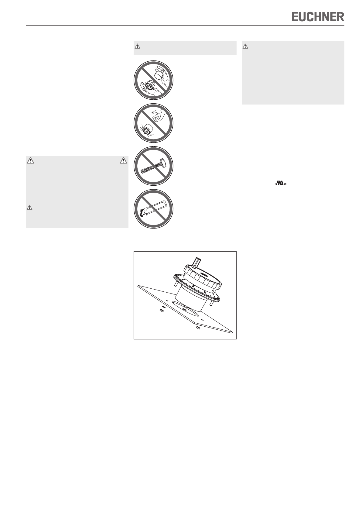
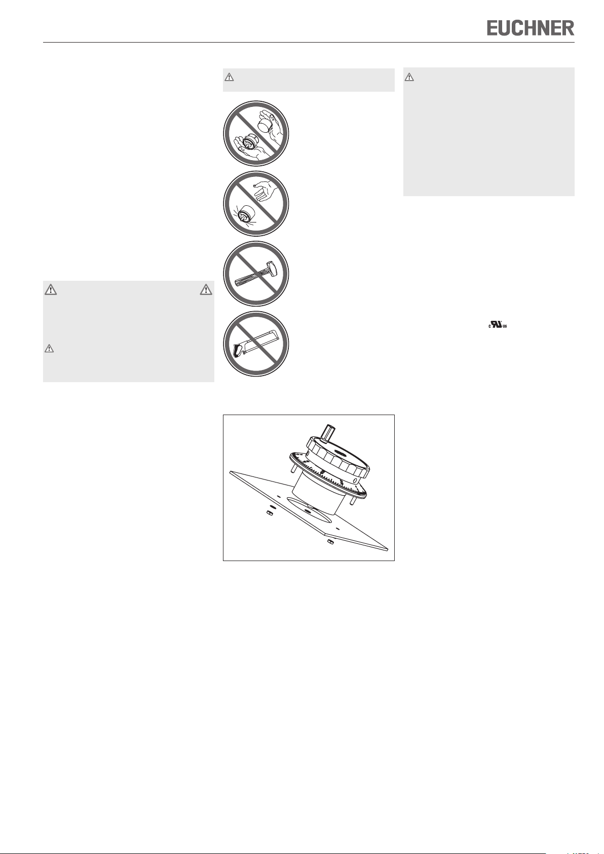
Montage
Die Montage darf ausschließlich von autorisier-
tem Fachpersonal durchgeführt werden.
Handräder nicht öffnen!
Handräder nicht werfen
oder fallen lassen!
Ke ine Schl äge auf die
Handräder ausüben!
Handräder nicht mechanisch bearbeiten!
Die Montage des Handrades erfolgt mit Muttern über
3 Gewindebolzen M3.
Bild 1: Montage Handrad
Elektrischer Anschluss
Der elektrische Anschluss darf ausschließlich von
autorisiertem, EMV-geschultem Fachpersonal
bei ausgeschalteter Maschine und in span-
nungsfreiem Zustand durchgeführt werden.
Die Maschine muss gegen Wiedereinschal-
ten gesichert sein.
Falscher Anschluss kann das Handrad
beschädigen.
Elektrische Kennwerte und Anschlussbelegung
beachten (siehe technische Daten).
Anschlussleitungen immer geschirmt ausführen.
Den Schirm am Leitungsende an einem zentralen
Massepunkt, z.B. im Verteiler oder im Schaltschrank, großflächig, niederohmig und induktivitätsarm erden.
Den Schirm an der Handrad-Schraubklemme Pin y
auflegen.
Anschlussleitungen nicht in unmittelbarer Nähe von
Störquellen verlegen.
Beim Anschluss hat der Betreiber für die Einhal-
tung der gültigen EMV-Schutzanforderungen zu
sorgen.
Zulassung nach : Betrieb nur mit UL-class 2
Spannungsversorgung, Gehäuseart UL-type 1.
Wartung und Kontrolle
EUCHNER Handräder sind wartungsfrei.
Die Instandsetzung von Handrädern darf nur durch
den Hersteller erfolgen.
Die Reinigung der Handräder darf nur mit lösungs-
mittelfreien Reinigungsmitteln und mit einem weichen
Tuch erfolgen.
Haftungsausschluss
Unter folgenden Punkten ist eine Haftung ausgeschlossen:
Nicht bestimmungsgemäßer Gebrauch
Nichteinhalten der Sicherheitshinweise
Elektrischer Anschluss durch nichtautorisiertes
Personal
Bei Manipulation
Hinweise zum Zählen der Handradimpulse beim Handrad HKC
Zum Zählen der Handradimpulse werden folgende
Lösungen empfohlen:
geeignetes Zählermodul
Phasendiskriminator
Page 2
Betriebsanleitung Elektronisches Handrad HKC
<39>
63
9
<
46>
M
3
31
73
2
- 6
78
47
72
±0,1
3,4
120°
3 x
120°
(=360°)
80
UB0V A B
90°
360°
A
B
200 µs
400 µs
800 µs
A
B
UB0V A B/A /B
90°
360°
A
/A
B
/B
200 µs 400 µs
800 µs
A
/A
B
/B
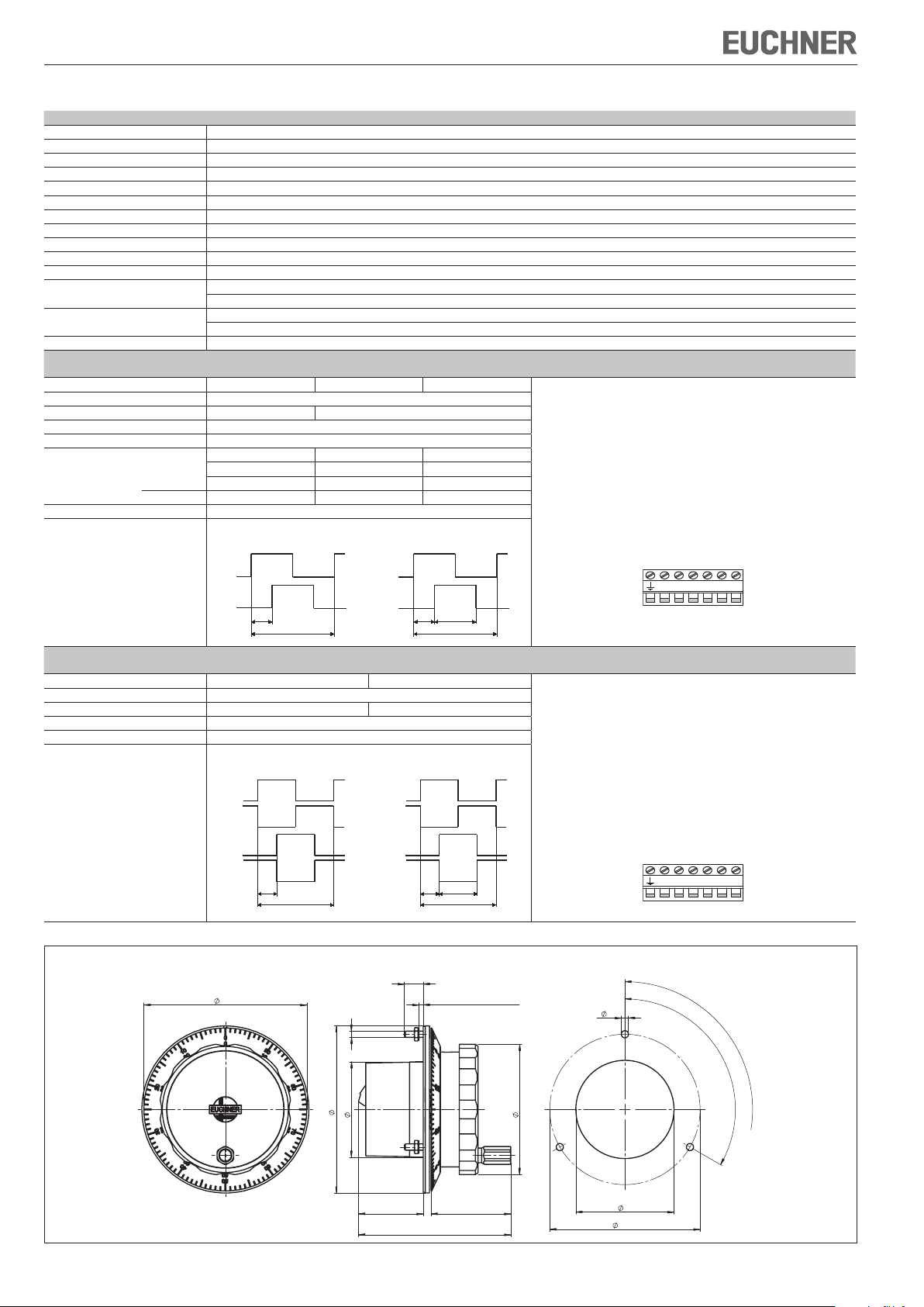
Technische Daten
Parameter Wert
Impulse pro Umdrehung 2 x 25 oder 2 x 100
Raststellungen 100
Gehäusewerkstoff Aluminium
Masse (ohne Einstellrad) 95 g
Magnetische Rastung 0,02 ... 0,04 Nm
Wellenbelastung axial, max. 25 N
Wellenbelastung radial, max. 40 N
Lebensdauer mechanisch, min. 5 x 10⁶ U
Betriebstemperatur 0 °C ... +50 °C
Lagertemperatur -20 °C ... +50 °C
Luftfeuchtigkeit, max. 80 % (Betauung unzulässig)
Schutzart frontseitig nach EN 60529 / IEC 529 IP 65
Widerstandsfähigkeit gegenüber
Vibrationen
EMV-Schutzanforderungen gemäß CE EN 61000-6-2, EN 61000-6-4
Ausgangsschaltung
Gegentakt
Ausgangsstufe G05 G12 G24 Anschlussbelegung
Ausgangssignale A, B
Betriebsspannung U
Betriebsstrom ohne Last, max. 80 mA
B
Ausgangsspezifikationen
Ausgangsspannung. HIGH (1), min. 4,0 V / 0 mA 4,9 V / 0 mA –
LOW (0), max. 1,3 V / 15 mA 1,3 V / 15 mA 3 V / 20 mA
Ausgangsstrom je Ausgang, max. 20 mA
Ausgangssignale
nach NEMA 250-12
Schwingungen (3 Achsen) DIN/IEC 68-2-6
Schock (3 Achsen) DIN/IEC 68-2-27
DC 5 V ± 5 % DC 10 ... 30 V
3,4 V / 5 mA 3,9 V / 5 mA –
3,0 V / 20 mA 3,6 V / 20 mA UB - 3 V / 20 mA
25 Impulse
100 Impulse
Schraubklemme 7-polig
Adernquerschnitt
0,08² ... 1,5²
(AWG 22 ... 16)
Anzugsdrehmoment
max. 0,25 Nm
Zu verwenden sind
Kupferleiter mit einer
Temperaturfestigkeit
von 75°C
Ausgangsschaltung
RS422
Ausgangsstufe A05 A12 Anschlussbelegung
Ausgangssignale A, /A, B, /B
Betriebsspannung U
Betriebsstrom ohne Last, max. 80 mA
B
Ausgangsspezifikationen
Ausgangssignale
DC 5 V ± 5 % DC 10 ... 30 V
entsprechend RS422A
25 Impulse
100 Impulse
Schraubklemme 7-polig
Adernquerschnitt
0,08² ... 1,5²
(AWG 22 ... 16)
Anzugsdrehmoment
max. 0,25 Nm
Zu verwenden sind
Kupferleiter mit einer
Temperaturfestigkeit
von 75°C
Schalttafelauschnitt
Schalttafeldicke
Technische Änderungen vorbehalten, alle Angaben ohne Gewähr. © EUCHNER GmbH + Co. KG 104604-02-05/09 (Originalbetriebsanleitung)
Bild 2: Maßzeichnung Handrad HKC
EUCHNER GmbH + Co. KG Kohlhammerstraße 16 D-70771 Leinfelden-Echterdingen Tel. +49/711/75 97-0 Fax +49/711/75 33 16 www.euchner.de info@euchner.de
Page 3
Operating instructions for electronic handwheel HKC
Correct use
The EUCHNER handwheel is a universal pulse generator for manual shaft positioning.
The handwheel is primarily used for positioning NCdriven machine tools during set-up.
Handwheels are used as part of an overall higherlevel control system.
Their use, installation and operation are permissible
only in conformity with these Operating Instructions.
Correct use includes compliance with the relevant
requirements for installation and operation, in
particular
EN 60204, electrical equipment of machines
EN 12100, safety of machines, general design
principles
EN ISO 13849-1, safety-related parts of control
systems
Safety precautions
EUCHNER handwheels HKC meet the EMC protection requirements according to EN 61000-6-2 and
EN 61000-6-4.
Handwheels HKC must not be used for residential
applications, in business or commercial areas or
in small businesses.
Appropriate safety measures must be taken to
prevent a malfunction of the handwheel which
could cause danger to human beings or damage to operating equipment.
Function
Two square-wave outputs of 100 or 25 pulses per
revolution are available for the user.
A second phase-shifted output allows the connected
control to detect the direction of movement.
The pulses are evaluated in the control.
The detent mechanism is magnetic and is therefore
totally wear-free.
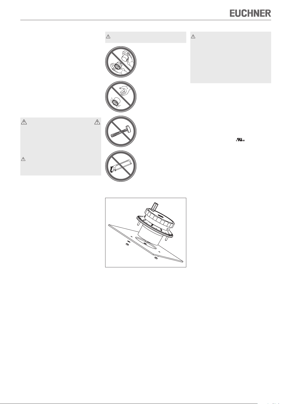
Assembly
The unit may only be assembled by authorised
personnel.
Do not open the
handwheels!
Do not throw or drop the
handwheels!
Do not hit the handwheels!
Do not use tools on the
handwheels!
The handwheel is assembled with nuts on 3 threaded
M3 bolts.
Electrical connection
Electrical connection may only be performed by
authorised personnel trained in EMC with the
machine switched off and in de-energised
state.
The machine must be safeguarded against
reactivation.
If connected incorrectly, the handwheel
may be damaged.
Observe electrical characteristics and the pin
assignments (see technical data)
Always shield connecting leads.
Ground the shield at the end of the lead at a central
grounding point, e.g. in the distribution board or in
the control cabinet, over a large surface, with low
resistance and with low inductance.
Apply shielding to handwheel screw terminal pin y.
Do not install connecting leads in the immediate
vicinity of interference sources.
When installing connections, the operator must
ensure compliance with the EMC safety requirements.
Authorisation according to : operation with
power supply of UL-class 2 only, housing type
UL-type 1.
Service and inspection
EUCHNER handwheels require no maintenance.
Handwheels may only be repaired by the manu-
facturer.
To clean the handwheels, only use solvent-free clean-
ing agents and a soft cloth.
Disclaimer of liability
The company does not accept liability regarding the
following cases:
if the unit is not used for its intended purpose
if the safety instructions are not followed
if the units are electrically connected by unautho-
rised personnel
if the units are tampered with
Fig. 1: Handwheel installation
Instructions for counting the handwheel
pulses: Handwheel HKC
The following options are recommended for counting
the handwheel pulses:
suitable counter module
phase discriminator
Page 4
Operating instructions for electronic handwheel HKC
UB0V A B
90°
360°
A
B
200 µs
400 µs
800 µs
A
B
UB0V A B/A /B
90°
360°
A
/A
B
/B
200 µs 400 µs
800 µs
A
/A
B
/B
<39>
63
9
<
46>
M
3
31
73
2
- 6
78
47
72
±0,1
3,4
120°
3 x
120°
(=360°)
80
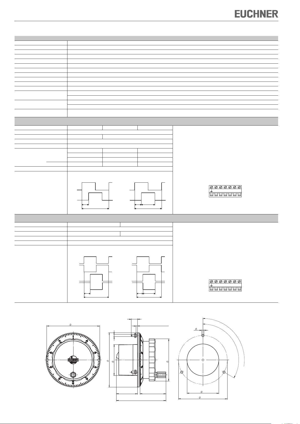
Technical data
Parameters Value
Pulses per revolution 2 x 25 or 2 x 100
Detent positions 100
Housing material Aluminium
Weight 95 g
Magnetic detent mechanism 0,02 ... 0.04 Nm
Shaft loading, axial, max. 25 N
Shaft loading, radial, max. 40 N
Mechanical service life, min. 5 x 10⁶ U
Operating temperature 0 °C ... +50 °C
Storage temperature -20 °C ... +50 °C
Humidity, max. 80 % (condensation not permissible)
Degree of protection to the front In accordance with EN 60529 / IEC 529 IP 65
Resistance to Vibrations (3 axes) DIN/IEC 68-2-6
EMC protection requirements in acc.
with CE
Output circuit
Push-pull
Output stage G05 G12 G24 Pin assignment
Output signals A, B
Operating voltage U
Operating current, no load, max. 80 mA
B
Output specifications
Output voltage HIGH (1), min. 4.0 V / 0 mA 4.9 V / 0 mA –
LOW (0), max. 1.3 V / 15 mA 1.3 V / 15 mA 3 V / 20 mA
Output current per output, max. 20 mA
Output signals
In accordance with NEMA 250-12
vibration Shock (3 axes) DIN/IEC 68-2-27
EN 61000-6-2, EN 61000-6-4
DC 5 V ± 5 % DC 10 ... 30 V
3.4 V / 5 mA 3.9 V / 5 mA –
3.0 V / 20 mA 3.6 V / 20 mA UB - 3 V / 20 mA
25 pulses
100 pulses
Screw terminal 7-pole
Wire cross-section
0.08² ... 1.5²
(AWG 22 ... 16)
Tightening torque
max. 0.25 Nm
It is necessary to use
copper conductors with
temperature resistance
of 75°C
Output circuit
RS422
Output stage A05 A12 Pin assignment
Output signals A, /A, B, /B
Operating voltage U
Operating current, no load, max. 80 mA
B
Output specifications
Output signals
DC 5 V ± 5 % DC 10 ... 30 V
In accordance with RS422A
25 pulses
100 pulses
Screw terminal 7-pole
Wire cross-section
0.08² ... 1.5²
(AWG 22 ... 16)
Tightening torque
max. 0.25 Nm
It is necessary to use
copper conductors with
temperature resistance
of 75°C
Front panel cut-out
Front panel thickness
Subject to technical modifications; no responsibility is accepted for the accuracy of this information. © EUCHNER GmbH + Co. KG 104604-02-05/09 (Translation of the original operating instructions)
Fig. 2: Dimension drawing of handwheel HKC
EUCHNER GmbH + Co. KG Kohlhammerstraße 16 D-70771 Leinfelden-Echterdingen Tel. +49/711/75 97-0 Fax +49/711/75 33 16 www.euchner.de info@euchner.de
Page 5

Mode d’emploi de la manivelle électronique HKC
Utilisation conforme
La manivelle électronique EUCHNER est un générateur d’impulsions universel destiné au déplacement
manuel des axes.
Elle est destinée en premier lieu au positionnement
en mode réglage des machines-outils pilotées par
CN.
Les manivelles font partie intégrante d’un système
global.
La mise en service, le montage et le fonctionnement ne sont autorisés qu’en respectant ce mode
d’emploi.
Pour que l‘utilisation soit conforme, les instructions
applicables au montage et à la mise en service
doivent être respectées, en particulier
EN 60204, Equipement électrique des machines
EN 12100, Sécurité des machines, principes
généraux de conception
EN ISO 13849-1, Parties des systèmes de com-
mande relatives à la sécurité
Consignes de sécurité
Les manivelles électroniques HKC de EUCHNER
répondent aux exigences de protection CEM conformément à EN 61000-6-2 et EN 61000-6-4.
Les manivelles HKC ne doivent pas être installées dans des quartiers résidentiels, des zones
commerciales et d’affaires ainsi que dans les
commerces.
Des mesures de sécurité appropriées doivent
être prises afin d’éliminer tout danger pour
les personnes et tout dommage sur l’outillage
provoqués par un défaut de fonctionnement de
la manivelle électronique.
Fonction
A la sortie, l’utilisateur dispose resp. de 100 ou 25
impulsions par tour (signal carré).
Une deuxième sortie en quadrature permet à la
commande placée en aval de reconnaître le sens
du mouvement.
L’analyse des impulsions s’effectue au niveau de
la commande.
Le crantage est magnétique et donc absolument
inusable.
Montage
Le montage doit être effectué exclusivement
par un personnel habilité.
Ne pas ouvrir !
Ne pas jeter, ni laisser
tomber !
Ne pas heurter !
Ne pas modifier mécaniquement !
Le montage de la manivelle électronique s’effectue
grâce à des écrous via 3 goujons M3.
Fig. 1 : montage de la manivelle électronique
Raccordement électrique
Le raccordement électrique doit être effectué
exclusivement par un personnel habilité et
formé à la CEM, sur une machine hors ten-
sion et déconnectée.
Prendre les mesures nécessaires pour
éviter une remise en route.
Un raccordement incorrect peut endom-
mager la manivelle électronique.
Respecter les paramètres électriques et l’af
fectation des broches (voir caractéristiques
techniques).
Les câbles de raccordement doivent toujours être
blindés.
Le blindage des câbles doit être mis à la terre au ni-
veau d’une masse centrale, par ex. dans le coffret
répartiteur ou l’armoire électrique, en assurant une
surface de contact suffisante et en respectant des
conditions d’impédance et d’inductance faibles.
Raccorder le blindage au niveau de la broche y
de la borne à vis.
Ne pas poser les câbles de raccordement à
proximité de sources parasites.
Lors du raccordement, l’utilisateur doit veiller au
respect des exigences de protection CEM.
Homologation : fonctionnement uniquement avec
alimentation UL-class 2, type de boîtier UL-type 1.
Entretien et contrôle
Les manivelles électroniques EUCHNER ne nécessitent pas d’entretien.
Seul EUCHNER est habilité à leur réparation.
Le nettoyage doit être effectué uniquement avec
des produits de nettoyage sans solvant et avec un
chiffon doux.
Exclusion de responsabilité
Les points suivants ne relèvent pas de la responsabilité du fabricant :
Utilisation non conforme
Non-respect des consignes de sécurité
Raccordement électrique par du personnel non
habilité
En cas d’intervention extérieure sur la manivelle
Indications pour le comptage des impulsions pour manivelle HKC
Les solutions suivantes sont recommandées pour
compter les impulsions :
Module de comptage adapté
Discriminateur de phase
-
Page 6

Mode d’emploi de la manivelle électronique HKC
UB0V A B
90°
360°
A
B
200 µs
400 µs
800 µs
A
B
UB0V A B/A /B
90°
360°
A
/A
B
/B
200 µs 400 µs
800 µs
A
/A
B
/B
<39>
63
9
<
46>
M
3
31
73
2
- 6
78
47
72
±0,1
3,4
120°
3 x
120°
(=360°)
80
Caractéristiques techniques
Paramètre Valeur
Impulsions par tour 2 x 25 ou 2 x 100
Nombre de positions par tour 100
Matériau du boîtier aluminium
Masse 95 g
Crantage magnétique 0,02 ... 0,04 Nm
Charge axiale max. sur l’arbre 25 N
Charge radiale max. sur l’arbre 40 N
Durée de vie mécanique, min. 5 x 10⁶ U
Température de service 0 °C ... +50 °C
Température de stockage -20 °C ... +50 °C
Humidité de l’air, max. 80 % (condensation interdite)
Indice de protection face avant selon EN 60529 / IEC 529 IP 65
Résistance aux vibrations Vibrations (3 axes) DIN/IEC 68-2-6
Exigences de protection CEM selon CE EN 61000-6-2, EN 61000-6-4
Sortie
symétrique
Etage de sortie G05 G12 G24 Brochage
Signaux de sortie A, B
Tension de service U
Courant de service sans charge, max. 80 mA
B
Spécifications de sortie
Tension de sortie HIGH (1), min. 4,0 V / 0 mA 4,9 V / 0 mA –
LOW (0), max. 1,3 V / 15 mA 1,3 V / 15 mA 3 V / 20 mA
Courant de sortie, max. par sortie 20 mA
Signaux de sortie
selon NEMA 250-12
Choc (3 axes) DIN/IEC 68-2-27
DC 5 V ± 5 % DC 10 ... 30 V
3,4 V / 5 mA 3,9 V / 5 mA –
3,0 V / 20 mA 3,6 V / 20 mA UB - 3 V / 20 mA
25 impulsions
100 impulsions
7 bornes à vis
Section des conducteurs
0,08² ... 1,5²
(AWG 22 ... 16)
Couple de serrage
max. 0,25 Nm
Veillez à utiliser
des conducteurs en
cuivre avec une
stabilité de température
de 75°C
Sortie
RS422
Etage de sortie A05 A12 Brochage
Signaux de sortie A, /A, B, /B
Tension de service U
Courant de service sans charge, max. 80 mA
B
Spécifications de sortie
Signaux de sortie
DC 5 V ± 5 % DC 10 ... 30 V
correspond à RS422A
25 impulsions
100 impulsions
7 bornes à vis
Section des conducteurs
0,08² ... 1,5²
(AWG 22 ... 16)
Couple de serrage
max. 0,25 Nm
Veillez à utiliser
des conducteurs en cuivre
avec une
stabilité de température
de 75°C
Découpe pour pupitre
Epaisseur de paroi
Sous réserve de modifications techniques, indications non contractuelles. © EUCHNER GmbH + Co. KG 104604-02-05/09 (Traduction du mode d’emploi original)
Fig. 2 : dimensions de la manivelle électronique HKC
EUCHNER GmbH + Co. KG Kohlhammerstraße 16 D-70771 Leinfelden-Echterdingen Tél. +49/711/75 97-0 Fax +49/711/75 33 16 www.euchner.de info@euchner.de
Page 7
Istruzioni di impiego volantino elettronico HKC
Impiego conforme alla destinazione
d’uso
Il volantino EUCHNER è un generatore di impulsi
universale per la regolazione manuale degli assi.
Esso serve prevalentemente per il posizionamento
delle macchine utensili con controllo NC in fase di
configurazione.
I volantini sono componenti che vengono inseriti in
sistemi di automazione.
L’utilizzo, l’installazione ed il funzionamento devono
avvenire esclusivamente secondo quanto riportato
nelle istruzioni di impiego.
L‘impiego conforme alla destinazione d‘uso implica
il rispetto delle vigenti norme relative all‘installazione
e all‘esercizio, in particolare
EN 60204, Equipaggiamento elettrico delle
macchine
EN 12100, Sicurezza delle macchine, principi
costruttivi generali
EN ISO 13849-1, Componenti di sicurezza dei
comandi.
Avvertenze di sicurezza
I volantini EUCHNER HKC sono conformi alla normativa EMV secondo EN 61000-6-2 e EN 61000-6-4.
Non utilizzare i volantini HKC in abitazioni, negozi,
aree commerciali e piccole aziende.
Adeguate misure di sicurezza nella costruzione
dei volantini permettono di escludere guasti di
funzionamento che possano causare lesioni alle
persone e danni alle attrezzature.
Funzionamento
All’uscita, il volantino fornisce 100 o 25 impulsi ad
onda quadra per giro.
Una seconda uscita sfasata consente ai sistemi di
controllo collegati di riconoscere la direzione del
movimento.
La valutazione degli impulsi avviene nel comando.
Il sistema di ritenuta è magnetico e quindi assoluta-
mente esente da usura.
Installazione
L’installazione deve essere eseguita esclusiva-
mente da personale specializzato autorizzato.
Non aprire il volantino!
Evitare cadute del
volantino!
Non colpire il volantino.
Non modificare meccanicamente il volantino.
L’installazione del volantino elettronico avviene con
3 dadi e 3 viti M3.
Collegamento elettrico
Il collegamento elettrico deve essere eseguito
esclusivamente da tecnici autorizzati e con
addestramento EMC a macchina spenta e in
mancanza di tensione.
La macchina deve essere messa in con-
dizione da non poter ripartire accidentalmente.
Dei collegamenti difettosi possono dan-
neggiare il volantino.
Prestare attenzione alle caratteristiche elettri
che e allo schema di collegamento (vedere dati
tecnici).
Realizzare sempre collegamenti con cavi scher-
mati.
È necessario assicurare la messa a terra della
schermatura dei cavi in un punto massa centrale,
ad esempio nel ripartitore o nel quadro elettrico,
caratterizzato da ampia superficie, bassa resistenza
e ridotto carico induttivo.
Collegare la schermatura al morsetto a vite, pin y.
Non posare i cavi di collegamento in prossimità di
fonti di disturbo.
Durante il collegamento, l’utente deve attenersi
alla normativa EMV.
Autorizzazione secondo : impiego esclusivo
con alimentazione di tensione classe UL 2, alloggiamento UL tipo 1.
Manutenzione e controllo
I volantini elettronici EUCHNER non richiedono
manutenzione.
Gli interventi di riparazione sui volantini devono
essere eseguiti solo dalla EUCHNER.
La pulizia dei volantini può essere eseguita esclusivamente con detergenti privi di solventi e con un
panno morbido.
Esonero delle responsabilità
L’esonero della responsabilità avviene in presenza
delle seguenti condizioni:
impiego non conforme alla destinazione d’uso
non ottemperanza delle istruzioni relative alla
sicurezza
collegamento elettrico eseguito da personale non
autorizzato
modifiche
-
Fig. 1: Installazione del volantino elettronico
Note per l’elaborazione degli impulsi
del volantino elettronico HKC
Per l’elaborazione degli impulsi del volantino si
consigliano le seguenti soluzioni:
Modulo di conteggio appropriato
Discriminatore di fase
Page 8

Istruzioni di impiego volantino elettronico HKC
UB0V A B
90°
360°
A
B
200 µs
400 µs
800 µs
A
B
UB0V A B/A /B
90°
360°
A
/A
B
/B
200 µs 400 µs
800 µs
A
/A
B
/B
<39>
63
9
<
46>
M
3
31
73
2
- 6
78
47
72
±0,1
3,4
120°
3 x
120°
(=360°)
80
Dati tecnici
Parametri Valore
Impulsi per rotazione 2 x 25 o 2 x 100
Posizioni di riposo 100
Materiale della custodia Alluminio
Massa 95 g
Ritenuta magnetica 0,02 ... 0,04 Nm
Carico applicato sull’albero assiale, max. 25 N
Carico applicato sull’albero radiale, max. 40 N
Durata meccanica, min. 5 x 10⁶ U
Temperatura d’esercizio 0°C ... +50°C
Temperatura di magazzinaggio -20°C ... +50°C
Umidità dell’aria, max. 80% (condensa non ammissibile)
Grado di protezione parte anteriore secondo EN 60529/IEC 529 IP 65
Resistenza alle vibrazioni Oscillazioni (3 assi) DIN/IEC 68-2-6
Norme di protezione EMV secondo CE EN 61000-6-2, EN 61000-6-4
Collegamento con uscita in
controfase
Stadio d’uscita G05 G12 G24 Schema di collegamento
Segnali d’uscita A, B
Tensione nominale di impiego U
Assorbimento senza carico, max. 80 mA
Specifiche d’uscita
Tensione d’uscita HIGH (1), min. 4,0 V / 0 mA 4,9 V / 0 mA –
LOW (0), max. 1,3 V / 15 mA 1,3 V / 15 mA 3 V / 20 mA
Corrente di uscita per ogni uscita, max. 20 mA
Segnali d’uscita
secondo NEMA 250-12
Shock (3 assi) DIN/IEC 68-2-27
B
DC 5 V ± 5% DC 10 ... 30 V
3,4 V / 5 mA 3,9 V / 5 mA –
3,0 V / 20 mA 3,6 V / 20 mA UB - 3 V / 20 mA
25 impulsi
100 impulsi
Morsetto a vite a 7 poli
per cavi sezione
0,08² ... 1,5²
(AWG 22 ... 16)
Coppia di serraggio
max. 0,25 Nm
Impiegare
conduttori di rame
con una
temperatura ammessa
di 75°C
Collegamento d’uscita
RS422
Stadio d’uscita A05 A12 Schema di collegamento
Segnali d’uscita A, /A, B, /B
Tensione nominale di impiego U
Assorbimento senza carico, max. 80 mA
B
Specifiche d’uscita
Segnali d’uscita
25 impulsi
DC 5 V ± 5% DC 10 ... 30 V
secondo RS422A
100 impulsi
Morsetto a vite a 7 poli
per cavi sezione
0,08² ... 1,5²
(AWG 22 ... 16)
Coppia di serraggio
max. 0,25 Nm
Impiegare
conduttori di rame
con una
temperatura ammessa
di 75°C
Dima di foratura
Spessore pannello
Con riserva di modifiche tecniche, tutti i dati esenti da garanzia. © EUCHNER GmbH + Co. KG 104604-02-05/09 (Traduzione delle istruzioni originali)
Fig. 2: Disegno quotato volantino HKC
EUCHNER GmbH + Co. KG Kohlhammerstraße 16 D-70771 Leinfelden-Echterdingen Tel. +49/711/75 97-0 Fax +49/711/75 33 16 www.euchner.de info@euchner.de
 Loading...