

Page 1
Betriebsanleitung Elektronisches Handrad HKA/HKC
Sicherheitshinweise
EUCHNER Handräder HKA/HKC entsprechen den
EMV-Schutzanforderungen nach EN 61000-6-2 und
EN 61000-6-4.
Handräder HKA/HKC dürfen nicht im Wohnbereich,
in Geschäfts- und Gewerbebereichen sowie in Kleinbetrieben eingesetzt werden.
Der Betreiber des übergeordneten Gesamtsystems
ist für das Einhalten der für den speziellen Einsatzfall geltenden nationalen und internationalen
Sicherheits- und Unfallvorschriften verantwortlich.
Bei der Maschinenplanung und Verwendung von
Handrädern sind die einsatzspezifischen nationalen und internationalen Sicherheits- und Unfallverhütungsvorschriften einzuhalten, wie z.B.:
EN 60204, Elektrische Ausrüstung von Maschinen
EN 12100, Sicherheit von Maschinen, allgemeine Gestaltungsleitsätze
EN 13849, Sicherheitsbezogene Teile von Steuerungen
Die Gefährdung von Menschen und die Beschädigung von Betriebseinrichtungen durch eine
Fehlfunktion des Handrades sind durch geeignete Sicherheitsmaßnahmen auszuschließen.
Bestimmungsgemäßer Gebrauch
Das Handrad von EUCHNER ist ein Universal-Impulsgeber zur manuellen Verstellung von Achsen.
Das Handrad dient überwiegend zur Positionierung
von NC-gesteuerten Werkzeugmaschinen im Einrichtebetrieb.
Handräder werden als Bestandteil eines übergeordneten Gesamtsystems eingesetzt.
Einsatz, Montage und Betrieb sind nur entsprechend dieser Betriebsanleitung zulässig.
Nichtbestimmungsgemäßer Gebrauch
Handräder allein dürfen nicht als Sicherheitselement zur Vermeidung von gefährdenden Zuständen in einer Maschinenanlage eingesetzt werden.
Funktion
Am Ausgang des Handrades stehen dem Anwender wahlweise 100 bzw. 25 Rechteckimpulse pro
Umdrehung zur Verfügung.
Ein zweiter um 90° phasenverschobener Ausgang
ermöglicht der nachgeschalteten Steuerung die Erkennung der Bewegungsrichtung.
Die Auswertung der Impulse erfolgt in der Steuerung.
Die Rastung ist magnetisch und somit absolut
verschleißfrei.
Montage
Die Montage darf ausschließlich von autorisiertem Fachpersonal durchgeführt werden.
Handräder nicht öffnen!
Handräder nicht werfen oder fallen lassen!
Keine Schläge auf die Handräder
ausüben!
Handräder nicht mechanisch bearbeiten!
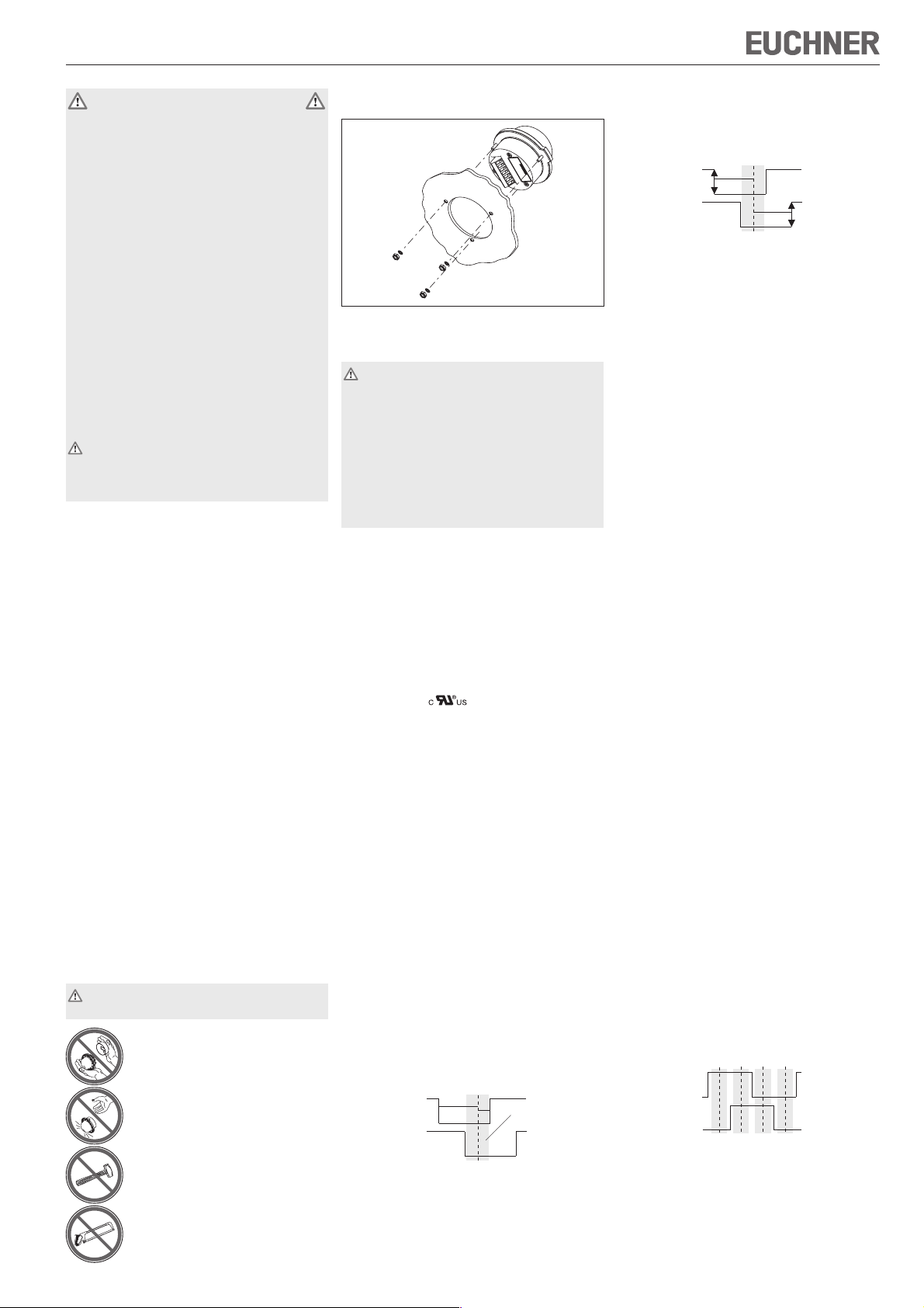
Die Montage des Handrades erfolgt mit Muttern
über 3 Gewindebolzen M3.
Bild 1: Montage Handrad HKA/HKC
Elektrischer Anschluss
Der elektrische Anschluss darf ausschließlich von
autorisiertem, EMV-geschultem Fachpersonal bei
ausgeschalteter Maschine und in spannungsfreiem Zustand durchgeführt werden.
Die Maschine muss gegen Wiedereinschalten gesichert sein.
Falscher Anschluss kann das Handrad beschädigen.
Elektrische Kennwerte und Anschlussbelegung
beachten (siehe technische Daten).
Anschlussleitungen immer geschirmt ausführen.
Den Schirm an der Handrad-Schraubklemme
Pin 댷 auflegen.
Den Schirm am Leitungsende an einem zentralen
Massepunkt, z.B. im Verteiler oder im Schaltschrank,
großflächig, niederohmig und induktivitätsarm erden.
Anschlussleitungen nicht in unmittelbarer Nähe
von Störquellen verlegen.
Beim Anschluss hat der Betreiber für die Einhaltung
der gültigen EMV-Schutzanforderungen zu sorgen.
Zulassung nach
: Betrieb nur mit UL-class
2 Spannungsversorgung, Gehäuseart UL-type 1.
Wartung und Kontrolle
EUCHNER Handräder sind wartungsfrei.
Die Instandsetzung von Handrädern darf nur durch
den Hersteller erfolgen.
Die Reinigung der Handräder darf nur mit lösungs-
mittelfreien Reinigungsmitteln und mit einem weichen
Tuch erfolgen.
Haftungsausschluss
Unter folgenden Punkten ist eine Haftung ausgeschlossen:
Nicht bestimmungsgemäßer Gebrauch
Nicht Einhaltung der Sicherheitshinweise
Elektrischer Anschluss durch nichtautorisiertes
Personal
Bei Manipulation
Hinweise zum Zählen der Handradimpulse
beim Handrad HKA100 und HKC100
In der Ruhelage (gerastete Position) haben beide
Ausgänge A und B den Zustand LOW.
a
b
A
B
Der Bereich der Ruhelage befindet sich bei der Bewegung im Uhrzeigersinn näher an der steigenden
A-Flanke (Abstand b), als bei der Bewegung entgegen dem Uhrzeigersinn (Abstand a).
Bereich der Ruhelage
Bei einer Zählmethode, die mit der Flanke des einen Ausgangs zählt und den anderen Ausgang zur
Drehrichtungserkennung verwendet, führt dies zu
einem sensiblen Verhalten in einer Richtung.
a
A
B
unkritische
Impulsflanken
a
Geeignete Zählweisen
Zum Zählen der Handradimpulse werden folgende
Lösungen empfohlen:
geeignetes Zählermodul
Phasendiskriminator
Mit Flanke von A zählen
Aufwärts
fallende Flanke von A und HIGHPegel an B
Abwärts
steigende Flanke von A und HIGHPegel an B
oder
mit Flanke von B zählen
Aufwärts
steigende Flanke von B und HIGHPegel an A
Abwärts
fallende Flanke von B und HIGHPegel an A
Hinweis für A05 und A12:
Sollten im Zählermodul diese Empfehlungen nicht
berücksichtigt werden können, wird das sensible
Verhalten möglicherweise durch folgende Anschlussmodifikation beseitigt:
Handradsignal AZählermodul-Eingang /A
Handradsignal /AZählermodul-Eingang A
Handradsignal B
Handradsignal /B
Zählermodul-Eingang /B
Zählermodul-Eingang B
Ungeeignete Zählweisen
Kritische Impulsflanken niemals zum Zählen verwenden!
Das Auftreten einer Impulsflanke alleine darf nicht
zu einer Bewegung z.B. an einem Maschinenteil
führen. Es muss sichergestellt sein, dass der Zähler erst dann weiterzählt, wenn das Handrad auch
tatsächlich die Position gewechselt hat.
Das Zählen alleine mit der steigenden/fallenden
Flanke von A, wobei B zur Richtungserkennung dient
(und umgekehrt), ist ungeeignet, weil durch eine
leichte Drehbewegung eine Impulsflanke ausgelöst
werden kann, obwohl sich das Handrad noch nicht
in der nächsten Raststellung befindet.
Durch eine leichte Drehbewegung wird eine Impulsflanke ausgelöst, obwohl noch nicht die nächste
Raststellung erreicht wurde.
Hinweise zum Zählen der Handradimpulse
beim Handrad HKA025 und HKC025
Im Bereich der Ruhelage nehmen die beiden Ausgangssignale folgende Zustände nacheinander ein:
A
B
Bereiche der Ruhelage
Geeignete Zählweisen
Zum Zählen der Handradimpulse werden folgende
Lösungen empfohlen:
geeignetes Zählermodul
Phasendiskriminator
Page 2
Betriebsanleitung Elektronisches Handrad HKA/HKC
/
/
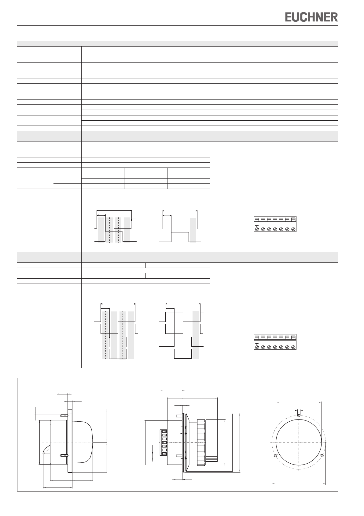
Technische Daten
Parameter Wert
Impulse pro Umdrehung 2 x 25 oder 2 x 100
Raststellungen 100
Gehäusewerkstoff Thermoplast
Masse 0,25 kg
Rastung magnetisch
Wellenbelastung axial, max. 25 N
Wellenbelastung radial, max. 40 N
Lebensdauer mechanisch, min. 20 x 106 U
Betriebstemperatur 0 °C ... +50 °C
Lagertemperatur -20 °C ... +50 °C
Luftfeuchtigkeit, max. 80 % (Betauung unzulässig)
Schutzart frontseitig nach EN 60529 / IEC 529 IP 65
Widerstandsfähigkeit Schwingungen (3 Achsen) DIN/IEC 68-2-6
gegenüber Vibrationen Schock (3 Achsen) DIN/IEC 68-2-27
EMV-Schutzanforderungen gemäß CE EN 61000-6-2, EN 61000-6-4
Ausgangsschaltung
Gegentakt
Ausgangsstufe G05 G12 G24 Anschlussbelegung
Ausgangssignale A, B
Betriebsspannung U
Betriebsstrom ohne Last, max. 80 mA
Ausgangsspezifikationen
Ausgangsspannung HIGH (1), min. 4,0 V / 0 mA 4,9 V / 0 mA –
Ausgangsstrom je Ausgang, max. 20 mA
Ausgangssignale
B
LOW (0), max. 1,3 V / 15 mA 1,3 V / 15 mA 3 V / 20 mA
nach NEMA 250-12
DC 5 V ± 5 % DC 10 ... 30 V
3,4 V / 5 mA 3,9 V / 5 mA –
3,0 V / 20 mA 3,6 V / 20 mA UB - 3 V / 20 mA
25 Impulse 100 Impulse
360˚
90˚
A
A
90˚
360˚
Schraubklemme 7-polig
Adernquerschnitt
0,08² ... 2,5²
(AWG 28 ... 12)
Anzugsdrehmoment
max. 0,5 Nm
Zu verwenden sind
Kupferleiter mit einer
Temperaturfestigkeit
von 75°C
UB0V A B
Technische Änderungen vorbehalten, alle Angaben ohne Gewähr. © EUCHNER GmbH + Co. KG 089117-05-12/07
B
Bereiche der Ruhelage Bereich der Ruhelage
Ausgangsschaltung
RS422
Ausgangsstufe A05 A12 Anschlussbelegung
Ausgangssignale A, /A, B, /B
Betriebsspannung U
Betriebsstrom ohne Last, max. 80 mA
Ausgangsspezifikationen entsprechend RS422A
Ausgangssignale
B
DC 5 V ± 5 % DC 10 ... 30 V
25 Impulse 100 Impulse
360˚
90˚
A
A
B
B
Bereiche der Ruhelage Bereich der Ruhelage
9
6,5
/A
/B
B
Schraubklemme 7-polig
Adernquerschnitt
0,08² ... 2,5²
(AWG 28 ... 12)
360˚
90˚
A
B
Handrad HKCHandrad HKA
34
24
3,5
45
Anzugsdrehmoment
max. 0,5 Nm
Zu verwenden sind
Kupferleiter mit einer
Temperaturfestigkeit
von 75°C
UB0V A B/A /B
Schalttafelausschnitt
M3
∅ 61
∅ 3,4
45
∅ 60
∅ 60
M3
∅ 63
∅ 78
∅ 80
R 41
30
40
28
8,5
∅ 72
Bild 2: Maßzeichnungen Handräder HKA/HKC
EUCHNER GmbH + Co. KG Kohlhammerstraße 16 D-70771 Leinfelden-Echterdingen Tel. +49/711/75 97-0 Fax +49/711/75 33 16 www.euchner.de info@euchner.de
Page 3
Operating instructions for electronic handwheel HKA/HKC
Safety precautions
EUCHNER handwheels HKA/HKC meet the EMC
protection requirements according to EN 61000-6-2
and EN 61000-6-4.
HKA/HKC handwheel must not be used for residential applications, in business or commercial areas or
in small business.
The operator of the overall higher-level system is
responsible for conformity with the national and
international safety and accident prevention regulations applicable to the special application.
When designing machines and using handwheels,
the national and international safety and accident
prevention regulations specific to the application
must be observed, e.g.:
EN 60204, electrical equipment of machines
EN 12100, safety of machines, general design
principles
EN 13849, safety-related parts of control
systems
Appropriate safety measures must be taken
to prevent a malfunction of the handwheel
which could cause danger to human beings or
damage to operating equipment.
Correct use
The EUCHNER handwheel is a universal pulse
generator for manual shaft positioning.
The handwheel is primarily used for positioning NCdriven machine tools during set-up.
Handwheels are used as part of an overall higherlevel control system.
Their use, installation and operation are permissible
only in conformity with these Operating Instructions.
Incorrect use
Handwheels on their own must not be used as
safety components for avoiding hazardous states
in a machine installation.
Function
Two square-wave outputs of 100 or 25 pulses per
revolution are available for the user.
A second output phase-shifted by 90° allows the
connected control to detect the direction of movement.
The pulses are evaluated in the control.
The detent mechanism is magnetic and is therefore
totally wear-free.
Assembly
The unit may only be assembled by authorised
personnel.
Do not open the handwheels!
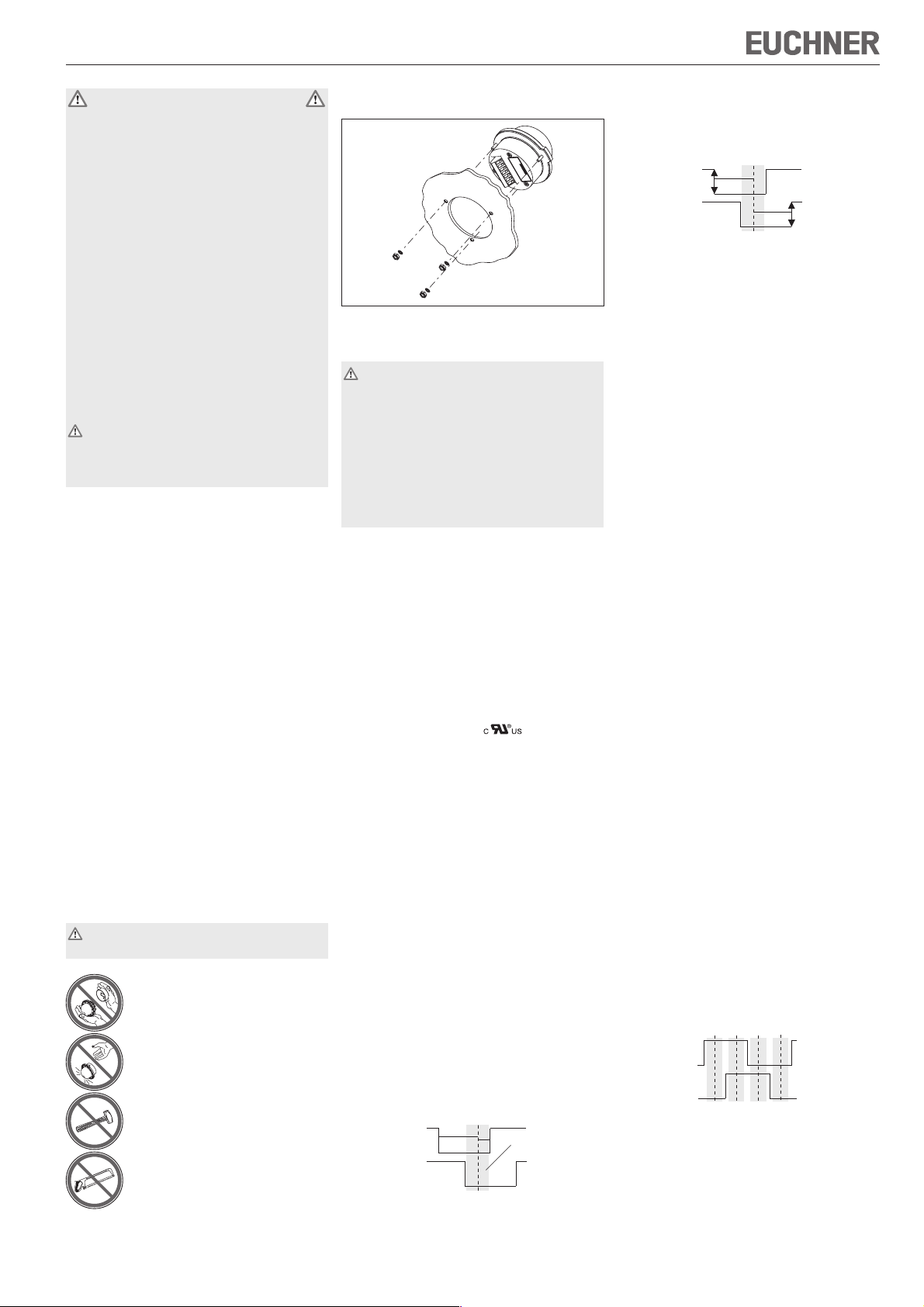
The handwheel is assembled with nuts on 3 threaded M3 bolts.
Fig. 1: Assembly of handwheel HKA/HKC
Electrical connection
Electrical connection may only be performed by
authorised personnel trained in EMC with the
machine switched off and in de-energised
state.
The machine must be safeguarded against
reactivation.
If connected incorrectly, the handwheel
may be damaged.
Observe electrical characteristics and the pin
assignments (see technical data)
Always shield connecting leads.
Apply shielding to handwheel screw terminal pin
댷
.
Ground the shield at the end of the lead at a central grounding point, e.g. in the distribution board
or in the control cabinet, over a large surface,
with low resistance and with low inductance.
Do not install connecting leads in the immediate
vicinity of interference sources.
When installing connections, the operator must
ensure compliance with the EMC safety requirements.
Authorisation according to : operation with
power supply of UL-class 2 only, housing type
UL-type 1.
Service and inspection
EUCHNER handwheels require no maintenance.
Handwheels may only be repaired by the manufac-
turer.
To clean the handwheels, only use solvent-free
cleaning agents and a soft cloth.
Disclaimer of liability
The company does not accept liability regarding
the following cases:
if the unit is not used for its intended purpose
if the safety instructions are not followed
if the units are electrically connected by unauthorised personnel
if the units are tampered with
Using a counting method which counts with the
edge of the output and uses the other output for
detecting the direction of rotation can result in sensitive behaviour in one direction.
a
A
B
Uncritical
pulse edges
a
Suitable counting methods
The following options are recommended for counting the handwheel pulses:
suitable counter module
phase discriminator
Count with the edge of A
Ascending
falling edge from A and HIGH
level at B
Descending
rising edge from A and HIGH
level at B
or
Count with the edges of B
Ascending
rising edge from B and HIGH
level at A
Descending
falling edge from B and HIGH
level at A
Note for A05 and A12:
If the recommended counting method does not
function properly, the signal behavior may be remedied by changing the following connection:
Handwheel signal A
Handwheel signal/A
Counter module input/A
Counter module input A
Handwheel signal BCounter module input/B
Handwheel signal/B
Counter module input B
Unsuitable counting methods
Never use critical pulse edges for counting!
On its own, the occurrence of a pulse edge must
not result in movement, e.g. of a machine component. Care must be taken to ensure that the counter does not increment until the position of the handwheel has actually changed.
Counting with the rising/falling edge of A - where B
assists the direction detection (and vice versa) - is
not suitable, because a pulse edge may be
triggered by a slight rotation even though the
handwheel has not yet reached the next detent
position.
A pulse edge is triggered by slight rotation even
though the next detent position has not yet been
reached.
Instructions for counting the handwheel
pulses: Handwheel HKA025 and HKC025
In the home position area, the two output signals
assume the following states in sequence.
Do not throw or drop the
handwheels!
Do not hit the handwheels!
Do not use tools on the handwheels!
Instructions for counting the handwheel
pulses: Handwheel HKA100 and HKC100
In the home position (detent position), outputs A
and B are both in the LOW state.
a
b
A
B
When it moves clockwise, the home position area is
located closer to the rising edge of A (distance b)
than when it moves counter-clockwise (distance a).
Home position area
A
B
Home position areas
Suitable counting methods
The following options are recommended for
counting the handwheel pulses:
suitable counter module
phase discriminator
Page 4

Operating instructions for electronic handwheel HKA/HKC
/
/
Technical data
Parameters Value
Pulses per revolution 2 x 25 or 2 x 100
Detent positions 100
Housing material Thermoplastic
Weight 0.25 kg
Detent mechanism Magnetic
Shaft loading, axial, max. 25 N
Shaft loading, radial, max. 40 N
Mechanical service life, min. 20 x 106 U
Operating temperature 0 °C ... +50 °C
Storage temperature -20 °C ... +50 °C
Humidity, max. 80 % (condensation not permissible)
Degree of protection to the front In accordance with EN 60529 / IEC 529 IP 65
Resistance to Vibrations (3 axes) DIN/IEC 68-2-6
vibration Shock (3 axes) DIN/IEC 68-2-27
EMC protection requirements in acc. with CE EN 61000-6-2, EN 61000-6-4
Output circuit
Push-pull
Output stage G05 G12 G24 Pin assignment
Output signals A, B
Operating voltage U
Operating current, no load, max. 80 mA
Output specifications
Output voltage HIGH (1), min. 4.0 V / 0 mA 4.9 V / 0 mA -
Output current per output, max. 20 mA
Output signals
B
LOW (0), max. 1.3 V / 15 mA 1.3 V / 15 mA 3 V / 20 mA
In accordance with NEMA 250-12
DC 5 V ± 5 % DC 10 ... 30 V
3.4 V / 5 mA 3.9 V / 5 mA -
3.0 V / 20 mA 3.6 V / 20 mA UB - 3 V / 20 mA
25 pulses 100 pulses
360˚
90˚
A
A
90˚
360˚
Screw terminal 7-pole
Wire cross-section
0.08² ... 2.5²
(AWG 28 ... 12)
Tightening torque
max. 0.5 Nm
It is necessary to use
copper conductors with
temperature resistance
of 75°C
UB0V A B
B
Home position areas Home position area
Output circuit
RS422
Output stage A05 A12 Pin assignment
Output signals A, /A, B, /B
Operating voltage U
Operating current, no load, max. 80 mA
Output specifications In accordance with RS422A
Output signals
B
DC 5 V ± 5 % DC 10 ... 30 V
25 pulses 100 pulses
360˚
90˚
A
A
B
B
Home position areas Home position area
9
6,5
/A
/B
B
Screw terminal 7-pole
Wire cross-section
0.08² ... 2.5²
(AWG 28 ... 12)
360˚
90˚
A
B
Handwheel HKCHandwheel HKA
34
24
3,5
45
Tightening torque
max. 0.5 Nm
It is necessary to use
copper conductors with
temperature resistance
of 75°C
UB0V A B/A /B
M3
Subject to technical modifications; no responsibility is accepted for the accuracy of this information. © EUCHNER GmbH + Co. KG 089117-05-12/07
Front panel cut-out
∅ 61
∅ 3,4
45
∅ 60
∅ 60
M3
∅ 63
∅ 78
∅ 80
R 41
30
40
28
8,5
∅ 72
Fig. 2: Dimension drawings of handwheel HKA/HKC
EUCHNER GmbH + Co. KG Kohlhammerstraße 16 D-70771 Leinfelden-Echterdingen Tel. +49/711/75 97-0 Fax +49/711/75 33 16 www.euchner.de info@euchner.de
Page 5

Mode d’emploi de la manivelle électronique HKA/HKC
Consignes de sécurité
Les manivelles électroniques HKA/HKC de EUCHNER
répondent aux exigences de protection CEM
conformément à EN 61000-6-2 et EN 61000-6-4.
Les manivelles électroniques HKA/HKC ne doivent
pas être installées dans des quartiers résidentiels,
des zones commerciales et d’affaires ainsi que
dans des commerces.
L’exploitant du système complet est responsable du
respect des normes nationales et internationales en
matière de sécurité et de prévention des accidents
en vigueur pour les applications spéciales.
A la conception de la machine, lors de l’utilisation
de manivelles électroniques, les normes nationales et internationales de sécurité et de prévention
d’accidents doivent être respectées, comme par
exemple :
EN 60204, Equipement électrique des machines
EN 12100, Sécurité des machines, principes
généraux de conception
EN 13849, Parties des systèmes de commande
relatives à la sécurité
Des mesures de sécurité appropriées doivent
être prises afin d’éliminer tout danger pour les
personnes et tout dommage sur l’outillage
provoqués par un défaut de fonctionnement
de la manivelle électronique.
Utilisation conforme
La manivelle électronique EUCHNER est un généra-
teur d’impulsions universel destiné au déplacement
manuel des axes.
Elle est destinée en premier lieu au positionnement en
mode réglage des machines-outils pilotées par CN.
Les manivelles font partie intégrante d’un système
global.
La mise en service, le montage et le fonctionnement
ne sont autorisés qu’en respectant ce mode d’emploi.
Utilisation non conforme
Les manivelles électroniques ne doivent pas être
les seuls éléments de sécurité devant éviter les
situations dangereuses sur une machine.
Fonction
A la sortie, l’utilisateur dispose resp. de 100 ou
25 impulsions par tour (signal carré).
Une autre sortie, déphasée de 90°, permet à la
commande placée en aval de détecter le sens de
déplacement.
L’analyse des impulsions s’effectue au niveau de
la commande.
Le crantage est magnétique et donc absolument
inusable.
Montage
Le montage doit être effectué exclusivement par
un personnel habilité.
Ne pas ouvrir !
Ne pas jeter, ni laisser tomber !
Ne pas heurter !
Ne pas modifier mécaniquement !
Le montage de la manivelle électronique s’effectue
grâce à des écrous via 3 goujons M3.
Fig. 1 : montage de la manivelle électronique HKA/HKC
Raccordement électrique
Le raccordement électrique doit être effectué
exclusivement par un personnel habilité et
formé à la CEM, sur une machine hors
tension et déconnectée
Prendre les mesures nécessaires pour
éviter une remise en route intempestive.
Un raccordement incorrect peut endom-
mager la manivelle électronique.
Respecter les paramètres électriques et
l’affectation des broches (voir caractéristiques
techniques).
Les câbles de raccordement doivent toujours être
blindés.
Raccorder le blindage au niveau de la broche
de la borne à vis.
Le blindage des câbles doit être mis à la terre au
niveau d’une masse centrale, par ex. dans le coffret
répartiteur ou l’armoire électrique, en assurant une
surface de contact suffisante et en respectant des
conditions d’impédance et d’inductance faibles.
Ne pas poser les câbles de raccordement à proximité de sources parasites.
Lors du raccordement, l’utilisateur doit veiller au
respect des exigences de protection CEM.
Homologation
: fonctionnement uniquement
avec alimentation UL-class 2, type de boîtier UL-type 1.
Entretien et contrôle
Les manivelles électroniques EUCHNER ne néces-
sitent pas d’entretien.
Seul EUCHNER est habilité à leur réparation.
Le nettoyage doit être effectué uniquement avec
des produits de nettoyage sans solvant et avec un
chiffon doux.
Exclusion de responsabilité
Les points suivants ne relèvent pas de la responsabilité du fabricant :
Utilisation non conforme
Non-respect des consignes de sécurité
Raccordement électrique par du personnel non
habilité
En cas d’intervention extérieure sur la manivelle
Indications pour le comptage des impulsions
de manivelle pour HKA100 et HKC100
En zone de repos, les 2 sorties A et B sont en
niveau bas.
La zone de repos est plus proche du front montant A
(distance b) lors du mouvement dans le sens horaire que
lors du mouvement dans le sens anti-horaire (distance a).
a
b
A
Zone de repos
B
La méthode de comptage, consistant à utiliser le
front d’une sortie pour le comptage et l’autre sortie
pour détecter le sens de rotation, conduit à un
comportement sensible dans un sens.
a
A
B
Fronts
d’impulsion
a
non critiques
Méthodes de comptage adaptées
Les solutions suivantes sont recommandées pour
compter les impulsions :
Module de comptage adapté
Discriminateur de phase
Comptage avec le front d’impulsion de A
Incrémentation
front descendant de A et
niveau haut sur B
Décrémentation
front ascendant de A et
niveau haut sur B
ou
Comptage avec le front d’impulsion de B
Incrémentation
front ascendant de B et
niveau haut sur A
Décrémentation
front descendant de B et
niveau haut sur A
Remarque pour A05 et A12 :
Si ces recommandations ne pouvaient être prises
en compte dans le module de comptage, le
댷
comportement sensible peut être corrigé par la
modification de raccord suivante :
Signal manivelle AEntrée module de comptage/ A
Signal manivelle/ A
Entrée module de comptage A
Signal manivelle BEntrée module de comptage/ B
Signal manivelle/ B
Entrée module de comptage B
Méthodes de comptage inadaptées
Ne jamais utiliser des fronts d’impulsion critiques
pour le comptage !
L’apparition d’un front d’impulsion unique ne doit
pas, par exemple, conduire au déplacement d’un
composant de la machine. Il faut s’assurer que le
compteur ne continue à s’incrémenter que si la
manivelle a effectivement changé la position.
Le comptage seul en utilisant le front ascendant/
descendant de A, avec B servant à la détection du
sens de rotation (et vice-versa), est inadapté, car
un léger mouvement de rotation peut provoquer
l’apparition d’un front d’impulsion, bien que la
manivelle ne se trouve pas encore dans la position
de crantage suivante.
Un léger mouvement de rotation provoque l’apparition
d’un front d’impulsion, bien que la position de crantage suivante n’ait pas encore été atteinte.
Indications pour le comptage des impulsions
de manivelle pour HKA025 et HKC025
En zone de repos, les deux signaux de sortie
adoptent successivement les états suivants :
A
B
Zones de repos
Méthodes de comptage adaptées
Les solutions suivantes sont recommandées pour
compter les impulsions :
Module de comptage adapté
Discriminateur de phase
Page 6

Mode d’emploi de la manivelle électronique HKA/HKC
/
/
Caractéristiques techniques
Paramètre Valeur
Impulsions par tour 2 x 25 ou 2 x 100
Nombre de positions par tour 100
Matériau du boîtier thermoplastique
Masse 0,25 kg
Crantage magnétique
Charge axiale max. sur l’arbre 25 N
Charge radiale max. sur l’arbre 40 N
Durée de vie mécanique, min. 20 x 106 U
Température de service 0 °C ... +50 °C
Température de stockage -20 °C ... +50 °C
Humidité de l’air, max. 80 % (condensation interdite)
Indice de protection face avant selon EN 60529 / IEC 529 IP 65
Résistance Vibrations (3 axes) DIN/IEC 68-2-6
aux vibrations Choc (3 axes) DIN/IEC 68-2-27
Exigences de protection CEM selon CE EN 61000-6-2, EN 61000-6-4
Sortie
symétrique
Etage de sortie G05 G12 G24 Brochage
Signaux de sortie A, B
Tension de service U
Courant de service sans charge, max. 80 mA
Spécifications de sortie
Tension de sortie HIGH (1), min. 4,0 V / 0 mA 4,9 V / 0 mA -
Courant de sortie, max. par sortie 20 mA
Signaux de sortie
B
LOW (0), max. 1,3 V / 15 mA 1,3 V / 15 mA 3 V / 20 mA
selon NEMA 250-12
DC 5 V ± 5 % DC 10 ... 30 V
3,4 V / 5 mA 3,9 V / 5 mA -
3,0 V / 20 mA 3,6 V / 20 mA UB - 3 V / 20 mA
25 impulsions 100 impulsions
360˚
90˚
A
B
A
B
90˚
360˚
7 bornes à vis
Section des conducteurs
0,08² ... 2,5²
(AWG 28 ... 12)
Couple de serrage
max. 0,5 Nm
Veillez à utiliser
des conducteurs en cuivre
avec une
stabilité de température
de 75°C
UB0V A B
Sous réserve de modifications techniques, indications non contractuelles. © EUCHNER GmbH + Co. KG 089117-05-12/07
Zones de repos Zone de repos
Sortie
RS422
Etage de sortie A05 A12 Brochage
Signaux de sortie A, /A, B, /B
Tension de service U
Courant de service sans charge, max. 80 mA
Spécifications de sortie correspond à RS422A
Signaux de sortie
B
9
DC 5 V ± 5 % DC 10 ... 30 V
25 impulsions 100 impulsions
360˚
90˚
A
A
B
B
Zones de repos Zone de repos
A
/A
B
/B
6,5
7 bornes à vis
Section des conducteurs
0,08² ... 2,5²
(AWG 28 ... 12)
360˚
90˚
Manivelle électronique HKCManivelle électronique HKA
Couple de serrage
max. 0,5 Nm
Veillez à utiliser
des conducteurs en cuivre
avec une
stabilité de température
de 75°C
UB0V A B/A /B
34
24
45
3,5
M3
Découpe pour pupitre
∅ 61
∅ 3,4
45
∅ 60
∅ 60
M3
∅ 63
∅ 78
∅ 80
R 41
30
40
28
8,5
∅ 72
Fig. 2 : dimensions des manivelles électroniques HKA/HKC
EUCHNER GmbH + Co. KG Kohlhammerstraße 16 D-70771 Leinfelden-Echterdingen Tél. +49/711/75 97-0 Fax +49/711/75 33 16 www.euchner.de info@euchner.de
Page 7

Istruzioni di impiego volantino elettronico HKA/HKC
Avvertenze di sicurezza
I volantini EUCHNER HKA/HKC sono conformi alla
normativa EMV secondo EN 61000-6-2 e EN 61000-6-4.
Non utilizzare i volantini HKA/HKC in abitazioni,
negozi, aree commerciali e piccole aziende.
L’utilizzo del dispositivo è soggetto all’osservanza
delle norme nazionali ed internazionali in tema di
sicurezza e di prevenzione infortuni di cui è responsabile il gestore del sistema.
Nella progettazione degli impianti e nell’utilizzo dei
volantini devono essere rispettate le norme nazionali ed internazionali di sicurezza e di prevenzione degli infortuni per casi specifici, come ad esempio:
EN 60204, equipaggiamento elettrico delle macchine
EN 12100, Sicurezza delle macchine, principi
costruttivi generali
EN 13849, Componenti di sicurezza dei comandi.
Adeguate misure di sicurezza nella costruzione
dei volantini permettono di escludere guasti
di funzionamento che possano causare lesioni
alle persone e danni alle attrezzature.
Impiego conforme alla destinazione d’uso
Il volantino EUCHNER è un generatore di impulsi
universale per la regolazione manuale degli assali.
Esso serve prevalentemente per il posizionamento
delle macchine utensili con controllo NC in fase di
configurazione.
I volantini sono componenti che vengono inseriti in
sistemi di automazione.
L’utilizzo, l’installazione ed il funzionamento devono
avvenire esclusivamente secondo quanto riportato
nelle istruzioni di impiego.
Impiego non conforme alla destinazione d’uso
I volantini non possono essere impiegati singolarmente come componenti di sicurezza per la
segnalazione di situazioni di pericolo in macchine
o impianti.
Funzionamento
All’uscita, il volantino fornisce 100 o 25 impulsi ad
onda quadra per giro.
Una seconda uscita sfasata di 90° consente ai sistemi di controllo collegati in serie di riconoscere
la direzione del moto.
La valutazione degli impulsi avviene nel comando.
La ritenuta è magnetica e quindi assolutamente
esente da usura.
Installazione
L’installazione deve essere eseguita esclusivamente da personale specializzato autorizzato.
Non aprire il volantino!
Evitare cadute del volantino!
Non colpire il volantino.
Non modificare meccanicamente
il volantino.
L’installazione del volantino elettronico avviene con
3 dadi e 3 viti M3.
Fig. 1: Installazione volantino HKA/HKC
Collegamento elettrico
Il collegamento elettrico deve essere eseguito
esclusivamente da tecnici autorizzati e con
addestramento EMC a macchina spenta e in
mancanza di tensione.
La macchina deve essere messa in con-
dizione da non potersi ripartire accidentalmente.
Dei collegamenti difettosi possono danneggiare il volantino.
Prestare attenzione alle caratteristiche elettriche e allo schema di collegamento (vedere
dati tecnici).
Realizzare sempre collegamenti con cavi schermati.
Collegare la schermatura al morsetto a vite, pin
댷
.
È necessario assicurare la messa a terra della
schermatura dei cavi in un punto massa centrale, ad
esempio nel ripartitore o nel quadro elettrico,
caratterizzato da ampia superficie, bassa resistenza
e ridotto carico induttivo.
Non posare i cavi di collegamento in prossimità
di fonti di disturbo.
Durante il collegamento, l’utente deve attenersi
alla normativa EMV.
Autorizzazione secondo
: impiego esclusivo
con alimentazione di tensione classe UL 2,
alloggiamento UL tipo 1.
Manutenzione e controllo
I volantini elettronici EUCHNER non richiedono
manutenzione.
Gli interventi di riparazione sui volantini devono
essere eseguiti solo dalla EUCHNER.
La pulizia dei volantini può essere eseguita esclusivamente con detergenti privi di solventi e con un
panno morbido.
Esonero delle responsabilità
L’esonero della responsabilità avviene in presenza
delle seguenti condizioni:
impiego non conforme alla destinazione d’uso
non ottemperanza con le istruzioni relative alla
sicurezza
collegamento elettrico eseguito da personale non
autorizzato
modifiche
Note per il calcolo degli impulsi del
volantino elettronico HKA100 e HKC100
In stato/posizione di riposo, entrambe le uscite A
e B si trovano in stato LOW.
a
b
A
B
Intervallo della posizione di riposo
L’intervallo della posizione di riposo, con movimento
in senso orario, è più prossimo al fianco ascendente
A (intervallo b) rispetto a quando il movimento
avviene in senso antiorario (intervallo a).
Un metodo di calcolo che utilizzi il fianco di un’uscita
per il conteggio e l’altra uscita per il riconoscimento della direzione di rotazione, porta ad un comportamento particolarmente sensibile in una direzione.
a
A
B
Fianchi degli
impulsi
a
non critici
Modalità di calcolo appropriate
Per il calcolo degli impulsi del volantino si consigliano le seguenti soluzioni:
Modulo di conteggio appropriato
Discriminatore di fase
Calcolo con il fianco A
Avanti
Indietro
Fronte di discesa di A e livello HIGH di B
Fronte di risalita di A e livello HIGH di B
oppure
Calcolo con il fianco B
Avanti
Indietro
Fronte di risalita di B e livello HIGH di A
Fronte di discesa di B e livello HIGH di A
Nota per A05 e A12:
Nel caso in cui non fosse possibile osservare tali
avvertenze nel modulo di conteggio, è possibile
eliminare tale „sensibilità“ effettuando la seguente
modifica di collegamento:
Segnale volantino elettronico A
Ingresso modulo di conteggio /A
Segnale volantino elettronico /A
Ingresso modulo di conteggio A
Segnale volantino elettronico B
Ingresso modulo di conteggio /B
Segnale volantino elettronico /B
Ingresso modulo di conteggio B
Modalità di calcolo non appropriate
Non impiegare mai i fianchi degli impulsi critici per
il calcolo.
La presenza di un solo fronte degli impulsi non deve
causare movimenti, ad esempio di un elemento
della macchina. Accertarsi che il contatore continui
il conteggio solo dopo l’effettiva modifica della
posizione del volantino.
Il calcolo con il solo fronte di risalita/di discesa di A,
in cui B serve per il riconoscimento della direzione (e
viceversa), non è appropriato in quanto un leggero
movimento rotatorio può azionare un fronte degli
impulsi, sebbene il volantino elettronico non abbia
ancora raggiunto la successiva posizione di riposo.
Con un leggero movimento rotatorio si attiva un
fronte degli impulsi, sebbene non sia stata ancora
raggiunta la successiva posizione di riposo.
Note per il calcolo degli impulsi del
volantino elettronico HKA025 e HKC025
Nell’intervallo della posizione di riposo, i due segnali
di uscita assumono nell’ordine le seguenti
condizioni:
A
B
Intervalli della posizione di riposo
Modalità di calcolo appropriate
Per il calcolo degli impulsi del volantino si consigliano le seguenti soluzioni:
Modulo di conteggio appropriato
Discriminatore di fase
Page 8

Istruzioni di impiego volantino elettronico HKA/HKC
/
/
Dati tecnici
Parametri Valore
Impulsi per rotazione 2 x 25 o 2 x 100
Posizioni di riposo 100
Materiale custodia Termoplastica
Massa 0,25 kg
Ritenuta magnetica
Carico applicato sull’albero assiale, max. 25 N
Carico applicato sull’albero radiale, max. 40 N
Durata meccanica, min. 20 x 106 U
Temperatura d’esercizio 0°C ... +50°C
Temperatura di magazzinaggio -20°C ... +50°C
Umidità dell’aria, max. 80% (condensa non ammissibile)
Grado di protezione parte anteriore secondo EN 60529/IEC 529 IP 65
Resistenza Oscillazioni (3 assi) DIN/IEC 68-2-6
alle vibrazioni Shock (3 assi) DIN/IEC 68-2-27
Norme di protezione EMV secondo CE EN 61000-6-2, EN 61000-6-4
Versione con uscita
in controfase
Stadio d’uscita G05 G12 G24 Schema di collegamento
Segnali d’uscita A, B
Tensione nominale di impiego U
Assorbimento senza carico, max. 80 mA
Specifiche d’uscita
Tensione d’uscita HIGH (1), min. 4,0 V / 0 mA 4,9 V / 0 mA -
LOW (0), max. 1,3 V / 15 mA 1,3 V / 15 mA 3 V / 20 mA
Corrente di uscita per ogni uscita, max. 20 mA
Segnali d’uscita
secondo NEMA 250-12
B
DC 5 V ± 5% DC 10 ... 30 V
3,4 V / 5 mA 3,9 V / 5 mA -
3,0 V / 20 mA 3,6 V / 20 mA UB - 3 V / 20 mA
25 impulsi 100 impulsi
360˚
90˚
A
90˚
A
360˚
Morsettiera a vite a 7
poli
sezione
0,08² ... 2,5²
(AWG 28 ... 12)
Coppia di serraggio
max. 0,5 Nm
Impiegare
cavi di rame con una
temperatura ammessa
di 75°C
UB0V A B
Con riserva di modifiche tecniche, tutti i dati esenti da garanzia. © EUCHNER GmbH + Co. KG 089117-05-12/07
B
Intervalli della posizione di riposo Intervallo della posizione di riposo
Versione con uscita
RS422
Stadio d’uscita A05 A12 Schema di collegamento
Segnali d’uscita A, /A, B, /B
Tensione nominale di impiego U
Assorbimento senza carico, max. 80 mA
Specifiche d’uscita secondo RS422A
Segnali d’uscita
B
DC 5 V ± 5% DC 10 ... 30 V
25 impulsi 100 impulsi
360˚
90˚
A
A
B
B
Intervalli della posizione di riposo Intervallo della posizione di riposo
9
6,5
/A
/B
B
Morsettiera a vite a 7
poli
sezione
0,08² ... 2,5²
360˚
90˚
A
B
Volantino elettronico HKCVolantino elettronico HKA
34
24
3,5
45
(AWG 28 ... 12)
Coppia di serraggio
max. 0,5 Nm
Impiegare
cavi di rame con una
temperatura ammessa
di 75°C
UB0V A B/A /B
Dima di foratura
M3
∅ 61
∅ 3,4
45
∅ 60
∅ 60
M3
∅ 63
∅ 78
∅ 80
R 41
30
40
28
8,5
∅ 72
Fig. 2: Disegni quotati volantino elettronico HKA/HKC
EUCHNER GmbH + Co. KG Kohlhammerstraße 16 D-70771 Leinfelden-Echterdingen Tel. +49/711/75 97-0 Fax +49/711/75 33 16 www.euchner.de info@euchner.de
 Loading...