

Page 1
Betriebsanleitung Handbediengeräte HBM
Diese Betriebsanleitung ist nur in Verbindung
mit dem Datenblatt des entsprechenden Handbediengeräts HBM und mit der Betriebsanleitung des dazugehörigen HKB-Handrads gültig!
Sicherheitshinweise
EUCHNER-Handbediengeräte HBM entsprechen den
EMV-Schutzanforderungen nach EN 61000-6-2 und
EN 61000-6-4.
Handbediengeräte HBM dürfen nicht im Wohnbereich, in Geschäfts- und Gewerbebereichen sowie
in Kleinbetrieben eingesetzt werden.
Der Betreiber des übergeordneten Gesamtsystems ist für das Einhalten der für den speziellen
Einsatzfall geltenden nationalen und internationalen Sicherheits- und Unfallvorschriften verantwortlich.
Bei der Maschinenplanung und Verwendung von
Handbediengeräten sind die einsatzspezifischen
nationalen und internationalen Sicherheits- und Unfallverhütungsvorschriften einzuhalten, wie z.B.
EN 60204, Elektrische Ausrüstung von Maschinen
EN 12100, Sicherheit von Maschinen, allgemeine Gestaltungsleitsätze
EN ISO 13849-1, Sicherheitsbezogene Teile von
Steuerungen
In Handbediengeräten geführte Spannungen
dürfen 30 V nicht überschreiten.
Die Gefährdung von Menschen und die Beschädigung von Betriebseinrichtungen durch eine
Fehlfunktion des Handbediengerätes sind
durch geeignete Sicherheitsmaßnahmen auszuschließen.
Mit Zustimmtasten allein dürfen keine Befehle
für gefahrenbringende Zustände eingeleitet werden. Hierzu ist ein zweiter bewusster
Startbefehl erforderlich.
Jede Person, die sich im Gefahrenbereich aufhält, muss einen eigenen Zustimmschalter mit
sich führen.
Verletzungsgefahr bei der Handhabung des
Handbediengerätes durch die hohe Anziehungskraft des Haftmagneten.
Abstand von Herzschrittmachern, magnetischen Datenträgern (Datenverlust), elektrischen und elektronischen Geräten halten.
Bestimmungsgemäßer Gebrauch
Mit Handbediengeräten werden Maschinenanlagen
im Handbetrieb bedient.
Handbediengeräte werden als Bestandteil eines
übergeordneten Gesamtsystems eingesetzt.
Einsatz, Montage und Betrieb sind nur entsprechend dieser Betriebsanleitung zulässig.
Nichtbestimmungsgemäßer Gebrauch
Handbediengeräte allein dürfen nicht als Sicherheitselement zur Vermeidung von gefährdenden Zuständen in einer Maschinenanlage eingesetzt werden.
Funktion allgemein
Handbediengeräte ermöglichen es, z.B. eine Maschinenanlage im Handbetrieb zu bedienen.
Funktion der Einzelkomponenten
Das Handbediengerät kann aus folgenden Komponenten bestehen:
Handrad
NOT-HALT-Einrichtung
Zustimmtasten
Stufenschalter
Drucktasten
HKB-Handrad
Das elektronische HKB-Handrad ist ein Universalimpulsgeber zum manuellen Verfahren von Achsen.
Am Ausgang stehen dem Anwender je nach Typ
100 oder 25 Rechteckimpulse pro Umdrehung zur
Verfügung. Ein zweiter phasenverschobener Ausgang ermöglicht der nachgeschalteten Steuerung
die Erkennung der Bewegungsrichtung.
Die Auswertung der Impulse erfolgt in der Steuerung.
Einzelheiten siehe Betriebsanleitung
HKB-Handrad
.
Elektronisches
NOT-HALT-Einrichtung
Die NOT-HALT-Einrichtung ist überlistungssicher
nach IEC 60947-5-1 / EN ISO 13850 ausgeführt.
Zustimmtasten, Stufenschalter, Drucktasten
Mit diesen Komponenten werden der übergeord-
neten Maschinensteuerung Zusatzinformationen
übergeben.
Montage
Handbediengeräte werden nicht standortgebunden
eingesetzt. Die Aufbewahrung oder Ablage erfolgt
über einen Haftmagneten an der Geräterückseite
oder über eine Halterung.
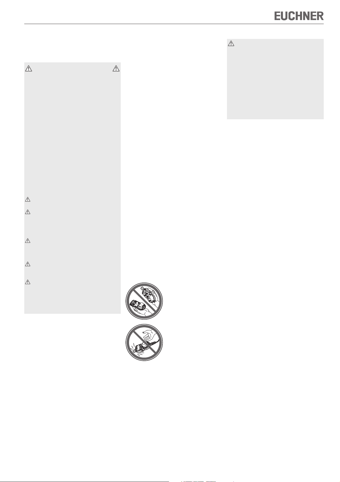
Handbediengeräte
nicht öffnen!
Handbediengeräte nicht
werfen oder fallen lassen!
Elektrischer Anschluss
Der elektrische Anschluss darf ausschließlich
von autorisiertem, EMV-geschultem Fachpersonal bei ausgeschalteter Maschine und in
spannungsfreiem Zustand durchgeführt wer-
den.
Die Maschine muss gegen Wiedereinschalten gesichert sein!
Falscher Anschluss kann Komponenten
des Handbediengerätes beschädigen!
Elektrische Kennwerte und Anschlussbelegung
beachten!
Die Anschlussbelegung ist dem Datenblatt zu
entnehmen.
Anschlussleitungen immer geschirmt ausführen.
Den Schirm am offenen Leitungsende an einem
zentralen Massepunkt, z.B. im Verteiler oder im
Schaltschrank, großflächig, niederohmig und
induktivitätsarm erden.
Bei Leitungen mit Steckverbindern ist für eine
EMV-gerechte Anschlussart zu sorgen.
Original Anschlussleitungen dürfen nicht gekürzt
werden.
Bei einer Verlängerung oder sonstigen Verände-
rung der Anschlussleitung hat der Betreiber für
die Einhaltung der gültigen EMV-Schutzanforderungen zu sorgen.
Anschlussleitungen nicht in unmittelbarer Nähe
von Störquellen verlegen.
Am Einsatzort installierte Anschlussleitungen von
Handbediengeräten müssen räumlich von beweglichen und fest installierten Leitungen und nicht isolierten aktiven Teilen anderer Anlagenteile, die mit
einer Spannung von über 150 V arbeiten, so getrennt werden, dass ein ständiger Abstand von 50,8
mm eingehalten wird. Es sei denn, die beweglichen
Leitungen sind mit geeigneten Isoliermaterialien versehen, die eine gleiche oder höhere Spannungsfestigkeit gegenüber den anderen relevanten Anlagenteilen besitzen.
Wartung und Kontrolle
EUCHNER Handbediengeräte sind wartungsfrei.
Die Instandsetzung von Handbediengeräten darf nur
durch den Hersteller erfolgen.
Die Reinigung der Handbediengeräte darf nur mit
lösungsmittelfreien Reinigungsmitteln und mit einem
weichen Tuch erfolgen.
Haftungsausschluss
unter folgenden Punkten ist eine Haftung ausgeschlossen:
nicht bestimmungsgemäßer Gebrauch
nicht Einhaltung der Sicherheitshinweise
Elektrischer Anschluss durch nichtautorisiertes
Personal
bei Fremdeingriff
Page 2

Betriebsanleitung Handbediengeräte HBM
Technische Daten, allgemein
Parameter Wert
Gehäusewerkstoff PBT-PC
Farbe anthrazit
Masse je nach Ausführung
Betriebstemperatur 0 °C ... +50 °C
Lagertemperatur -20 °C ... +50 °C
Luftfeuchtigkeit, max. 80 %
(Betauung unzulässig)
Schutzart frontseitig
nach EN 60529 / IEC529 IP 65
nach NEMA 250-12
Widerstandsfähigkeit
gegenüber Vibrationen
Schwingungen (3 Achsen) DIN/IEC 68-2-6
Schock (3 Achsen) DIN/IEC 68-2-27
EMV-Schutzanforderungen gemäß CE EN 61000-6-2
EN 61000-6-4
Technische Daten der
Komponenten
NOT-HALT Wert
Norm EN ISO 13850
Schaltelemente je nach Ausführung
Gebrauchskategorie DC-13
nach IEC 60947-5-1 Ue=24 V / Ie = 3A
Zustimmtasten Wert
Schaltelement je nach Ausführung
Ohmsche Belastung AC 30 V / 0,4 A
DC 30 V / 0,1 A
Drucktasten Wert
Schaltelement je nach Ausführung
Schaltspannung, max. DC 30 V
Schaltstrom, max. 0,1 A
Schaltleistung, max. 1 VA
Stufenschalter Wert
Schaltcode 1 aus X, Gray, Hex
siehe Anschlussplan
Schaltspannung, max. 25 V
Schaltleistung, max. 0,2 VA
Sonstige Komponenten
siehe Katalog EUCHNER Handbediengeräte bzw. www.euchner.de
Technische Änderungen vorbehalten, alle Angaben ohne Gewähr. © EUCHNER GmbH + Co. KG 112272-01-02/11 (Originalbetriebsanleitung)
Technische Daten Handrad
Siehe zugehörige Betriebsanleitung HKB-Handrad.
Zubehör
Siehe Katalog EUCHNER-Handbediengeräte bzw.
www.euchner.de.
EUCHNER GmbH + Co. KG Kohlhammerstraße 16 D-70771 Leinfelden-Echterdingen Tel. +49/711/75 97-0 Fax +49/711/75 33 16 www.euchner.de info@euchner.de
Page 3
Operating instructions for hand-held pendant stations HBM
These operating instructions are valid only in
connection with the data sheet of the relevant hand-held pendant station HBM and with
the operating instructions of the relevant HKB
handwheel!
Safety precautions
EUCHNER hand-held pendant stations HBM meet
the EMC protection requirements according to
EN 61000-6-2 and EN 61000-6-4.
Hand-held pendant stations HBM must not be used
for residential applications, in business or commercial areas or in small businesses.
The operator of the overall higher-level system is
responsible for conformity with the national and
international safety and accident prevention regulations applicable to the special application.
When designing machines and using handwheels,
the national and international safety and accident
prevention regulations specific to the application
must be observed, e.g.:
EN 60204, electrical equipment of machines
EN 12100, safety of machines, general design
principles
EN ISO 13849-1, safety-related parts of control
systems
Voltage applied to hand-held pendant stations
must not exceed 30 V.
Appropriate safety measures must be taken
to prevent a malfunction of the handwheel
which could cause danger to human beings or
damage to operating equipment.
No commands that may lead to potentially
hazardous conditions may be initiated by
enabling switches alone. In such case, a second, deliberate start command is required.
Every person present in the danger area must
carry his/her own enabling switch on his/her
person.
Risk of injury is present when handling the
hand-held pendant station due to the strong
attraction of the mounting.
Keep heart pacemakers, magnetic data carriers (data loss) and electrical and electronic
devices at a suitable distance.
Correct use
Machine installations in manual mode can be
operated with hand-held pendant stations.
Handwheels are used as part of an overall higherlevel control system.
Their use, installation and operation are permissible
only in conformity with these operating instructions.
Incorrect use
Hand-held pendant stations on their own must not
be used as safety components for avoiding hazardous states in a machine installation.
General function
Hand-held pendant stations make it possible to
operate a machine installation, for instance, in
manual mode.
Function of individual components
The hand-held pendant station may consist of the
following components:
Handwheel
EMERGENCY-STOP device
Enabling switches
Selector switches
Pushbuttons
HKB handwheel
The electronic HKB handwheel is a universal pulse
generator for manual shaft positioning.
An output of 100 or 25 square-wave pulses per
revolution is available. A second phase-shifted
output allows the connected controller to detect
the direction of movement.
The pulses are evaluated in the controller.
For details, please see the
Electronic HKB handwheel
operating instructions.
EMERGENCY-STOP device
The EMERGENCY-STOP device is designed to be manipulation-proof in accordance with IEC 60947-5-1/
EN ISO 13850.
Enabling switches, selector switches,
pushbuttons
These components are used to transfer additional
information to the higher-level machine controller.
Assembly
Hand-held pendant stations are not used exclusively
at a single site. The stations can be stored using a
mounting magnet on the rear of the device or a
holder.
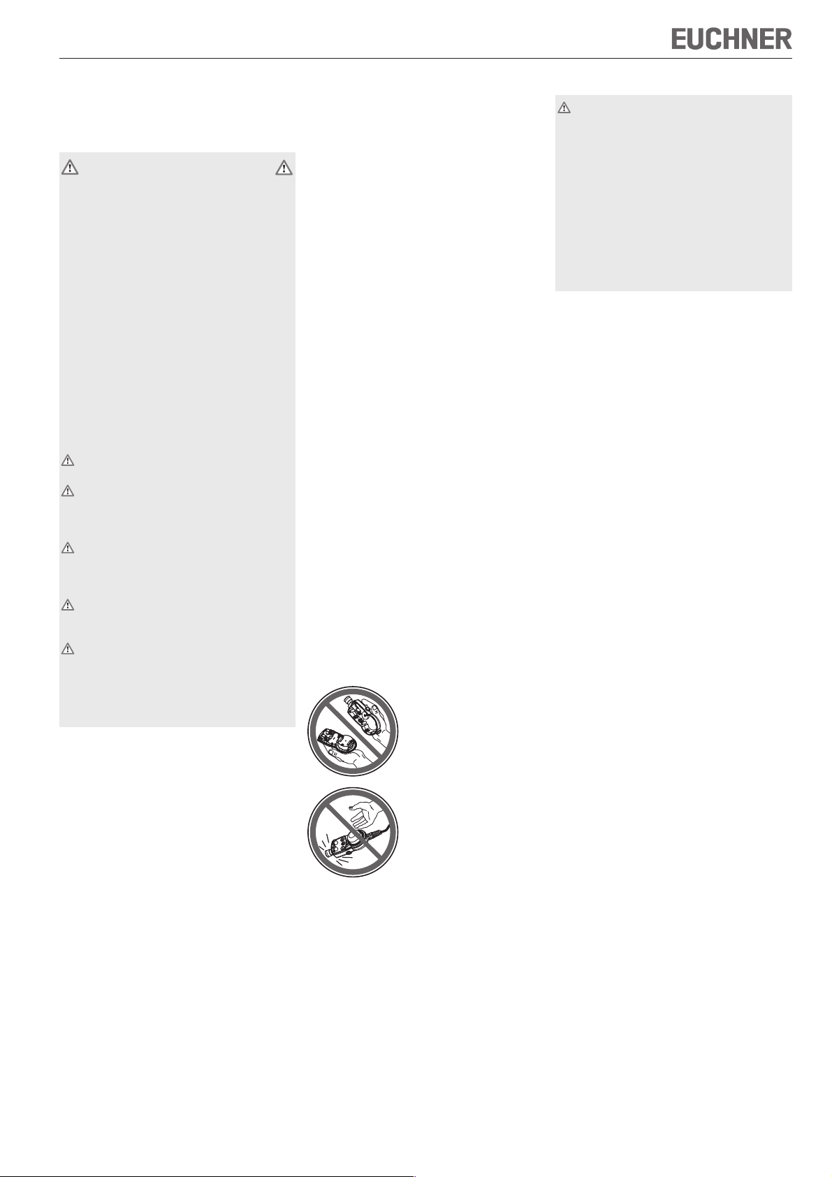
Do not open hand-held
pendant stations!
Do not throw or drop the
hand-held pendant stations!
Electrical connection
Electrical connection may only be performed
by authorised personnel trained in EMC with
the machine switched off and in a de-energised state.
The machine must be safeguarded against
reactivation.
Incorrect connection may cause damage
to the components of the hand-held pendant station!
Observe electrical characteristics and the pin
assignments!
The pin assignment can be found in the data
sheet.
Always shield connecting leads.
Ground the shield at the open end of the lead at
a central grounding point, e.g. in the distribution
board or in the control cabinet, over a large surface, with low resistance and with low inductance.
In the case of leads with plug connectors, ensure
that the connection type is EMC-compliant.
Original connecting leads must not be shortened.
Given an extension or other modification to the
connection cable, the operator must ensure that
the valid EMC protection requirements are observed.
Do not install connecting leads in the immediate
vicinity of interference sources.
Connection leads of hand-held pendant stations installed at the application site must be separated
from all movable and permanently installed leads
and non-insulated active parts of other installation
parts which operate with a voltage of over 150 V, in
such a way that a constant clearance of 50.8 mm is
observed. This does not apply if the movable leads
are equipped with suitable insulation materials which
possess an identical voltage stability to the other
relevant installation parts or higher.
Service and inspection
EUCHNER handwheels require no maintenance.
Handwheels may only be repaired by the manufac-
turer.
To clean the handwheels, only use solvent-free cle-
aning agents and a soft cloth.
Disclaimer of liability
The company is unable to accept liability in the
following cases:
if instructions are not followed
if the safety instructions are not followed
if the units are electrically connected by unauthorised personnel
if any external intervention occurs
Page 4

Operating instructions for hand-held pendant stations HBM
Technical data, general
Parameters Value
Housing material PBT-PC
Colour anthracite grey
Weight depending on version
Operating temperature 0 °C ... +50 °C
Storage temperature -20 °C ... +50 °C
Humidity, max. 80 %
Degree of protection to the front
In accordance with EN60529 / IEC529 IP 65
In accordance with NEMA 250-12
Resistance to
vibration
Vibrations (3 axes) DIN/IEC 68-2-6
Shock (3 axes) DIN/IEC 68-2-27
EMC protection requirements EN 61000-6-2
in accordance with CE EN 61000-6-4
Technical data of components
EMERGENCY STOP Value
Norm EN ISO 13850
Switching elements depending on version
Utilization category DC-13
according to IEC 60947-5-1 Ue=24 V / Ie = 3 A
Enabling switches Value
Switching element depending on version
Resistive load AC 30 V / 0.4 A
Pushbuttons Value
Switching element depending on version
Switching voltage, max. 30 V DC
Switching current, max. 0.1 A
Switching capacity, max. 1 VA
Selector switches Value
Switching code 1 of X, grey, hex
Switching voltage, max. 25 V
Switching capacity, max. 0,2 VA
Other components
See EUCHNER catalogue for hand-held pendant stations or
www.euchner.de
(condensation not permissible)
DC 30 V / 0.1 A
see wiring diagram
Technical data, handwheel
See relevant operating instructions for HKB handwheel.
Accessories
See EUCHNER catalogue for hand-held pendant
stations or www.euchner.de.
Subject to technical modifications; no responsibility is accepted for the accuracy of this information. © EUCHNER GmbH + Co. KG 112272-01-02/11 (translation of the original operating instructions)
EUCHNER GmbH + Co. KG Kohlhammerstraße 16 D-70771 Leinfelden-Echterdingen Tel. +49/711/75 97-0 Fax +49/711/75 33 16 www.euchner.de info@euchner.de
Page 5

Mode d’emploi des pupitres portables HBM
Le présent mode d’emploi n’est valable qu’en
lien avec la fiche technique correspondante
au pupitre portable HBM ainsi qu’avec le mode
d’emploi de la manivelle adaptée au HKB !
Consignes de sécurité
Les pupitres portables HBM de EUCHNER
répondent aux exigences de protection CEM
conformément à EN 61000-6-2 et EN 61000-6-4.
Il est interdit d’installer les pupitres portables HBM
dans des quartiers résidentiels, des zones
commerciales ou d’affaires ainsi que dans des
petits commerces.
L’utilisateur du système global est responsable
du respect des normes nationales et internationales en vigueur pour les applications spéciales, en
matière de sécurité et de prévention des accidents.
A la conception de la machine, lors de l’utilisation
de pupitres portables, les normes nationales et
internationales de sécurité et de prévention
d’accidents doivent être respectées, comme par
exemple :
EN 60204, Equipement électrique des machines
EN 12100, Sécurité des machines, principes
généraux de conception
EN ISO 13849-1, Parties des systèmes de
commande relatives à la sécurité
Les tensions circulant dans les pupitres
portables ne doivent pas excéder 30 V.
Des mesures de sécurité appropriées doivent
être prises afin d’éliminer tout danger pour les
personnes et tout dommage sur l’outillage
provoqués par un défaut de fonctionnement
du pupitre portable.
Les commandes d’assentiment seules ne doivent pas être utilisées pour des comman-
des susceptibles d’engendrer des risques.
Pour cela, une commande séparée de démar-
rage est nécessaire.
Chaque personne se tenant dans la zone de danger doit porter sur elle sa propre commande
d’assentiment.
Risque de blessures lors de la manipulation
du pupitre portable dû à une forte attraction
de l’aimant adhérent.
Éloigner les personnes cardiaques portant un
pacemaker, les supports magnétiques
d’informations (perte des données), les appareils électriques et électroniques.
Utilisation conforme
Les machines peuvent être pilotées en mode
manuel par les pupitres portables.
Les pupitres portables font partie intégrante d’un
système global intelligent.
La mise en service, le montage et le fonctionnement ne sont autorisés qu’en respectant ce mode
d’emploi.
Utilisation non conforme
Les pupitres portables ne doivent pas être les
seuls éléments de sécurité devant éviter les
situations dangereuses sur une machine.
Fonction en général
Les pupitres portables permettent de piloter une
machine, par exemple en mode manuel.
Fonction des composants
Le pupitre portable peut comprendre les composants suivants :
Manivelle
Dispositif d’arrêt d’urgence
Commandes d’assentiment
Commutateurs
Boutons-poussoirs
Manivelle pour pupitre HKB
La manivelle électronique HKB est un générateur
d’impulsions universel destiné au déplacement
manuel des axes.
A la sortie, l’utilisateur dispose en fonction du type
de 25 ou 100 impulsions carrées par tour. Une
deuxième sortie en quadrature de phase permet
au système de commande de reconnaître le sens
du déplacement.
L’analyse des impulsions s’effectue au niveau de
la commande.
Pour des détails, voir le mode d’emploi de la
manivelle électronique adaptée au pupitre HKB
.
Dispositif d’arrêt d’urgence
Le dispositif d’arrêt d’urgence est protégé contre les
manipulations intempestives selon IEC 60947-5-1 /
EN ISO 13850.
Commandes d’assentiment, commutateurs, boutons-poussoirs.
Ces composants sont utilisés pour transmettre des
informations au système de commande de la machine.
Montage
Les pupitres portables peuvent être utilisés sur
plusieurs machines. Il est possible de les ranger
soit au moyen de l’aimant fixé au dos du boîtier,
soit avec le support prévu.
Ne pas ouvrir
les pupitres portables !
Ne pas jeter ni laisser tomber les pupitres portables !
Raccordement électrique
Le raccordement électrique doit être effectué
exclusivement par un personnel habilité et
formé à la CEM, sur une machine éteinte et
hors tension.
Prendre les mesures nécessaires pour
éviter une remise en route intempestive !
Un mauvais raccordement peut endom-
mager les composants du pupitre portable !
Respecter les paramètres électriques et
l’affectation des broches !
L’affectation des broches figure sur la fiche
technique.
Les lignes de raccordement doivent toujours être
blindées.
Le blindage de la ligne doit être mis à la terre au
niveau d’une masse centrale, par ex. dans le coffret répartiteur ou l’armoire électrique, en assurant
une surface de contact suffisante et en respectant des conditions d’impédance et d’inductance
faibles.
Le type de connexion conforme à la compatibilité
électromagnétique (CEM) doit être respecté pour
les câbles avec connecteurs.
Les lignes de raccordement d’origine ne doivent
pas être raccourcies.
L’utilisateur doit veiller au respect des exigences
de protection CEM valable, lors d’un rallongement
ou de toute autre modification du câble de raccordement.
Ne pas poser les lignes de raccordement à proximité de sources parasites.
Les câbles de raccordement des pupitres portables installés sur un site, doivent être séparés des
autres câbles électriques, mobiles ou fixes, et aux
autres composants non isolés, d’une distance minimale de 50,8 mm, si ceux-ci présentent une tension supérieure à 150 V. Ceci n’est pas nécessaire si
les câbles mobiles sont munis de matériaux isolants
adaptés, présentant une résistance diélectrique éga-
le ou supérieure aux autres composants importants
de l’installation.
Entretien et contrôle
Les pupitres portables EUCHNER ne nécessitent
pas d’entretien.
Seul EUCHNER est habilité à leur réparation.
Le nettoyage des pupitres portables doit être
effectué uniquement avec des produits de
nettoyage sans solvant et avec un chiffon doux.
Exclusion de responsabilité
Les points suivants ne relèvent pas de la responsabilité du fabricant :
utilisation non conforme
non-respect des consignes de sécurité
raccordement électrique par du personnel non
habilité
modification du circuit de l’appareil
Page 6

Mode d’emploi des pupitres portables HBM
Caractéristiques techniques,
généralités
Paramètre Valeur
Matériau du boîtier PBT-PC
Couleur gris anthracite
Masse selon la version
Température de service 0 °C ... +50 °C
Tem p érature de stockage -20 °C ... +50 °C
Humidité de l’air, max. 80 %
(condensation interdite)
Indice de protection face avant
conformément à EN60529 / IEC529 IP 65
selon NEMA 250-12
Résistance aux vibrations
Vibrations (3 axes) DIN/IEC 68-2-6
Choc (3 axes) DIN/IEC 68-2-27
Exigences de protection CEM selon CE EN 61000-6-2
EN 61000-6-4
Caractéristiques techniques
des composants
ARRET D’URGENCE Valeur
Norme EN ISO 13850
Eléments logiques selon la version
Catégorie d’utilisation DC-13
conformément à IEC 60947-5-1 Ue=24 V / Ie = 3A
Commande d’assentiment Valeur
Eléments logiques selon la version
Charge ohmique AC 30 V / 0,4 A
DC 30 V / 0,1 A
Boutons-poussoirs Valeur
Eléments logiques selon la version
Tension de commutation max. DC 30 V
Courant de commutation max. 0,1 A
Pouvoir de coupure max. 1 VA
Commutateur Valeur
Code de commutation 1 sur X, Gray, Hex
voir schéma de câblage
Tension de commutation max. 25 VA
Pouvoir de coupure max. 0,2 VA
Autres composants
voir catalogue EUCHNER, Pupitres portables ou www.euchner.de
Sous réserve de modifications techniques, indications non contractuelles. © EUCHNER GmbH + Co. KG 112272-01-02/11 (trad. mode d’emploi d’origine)
Caractéristiques techniques
manivelle
Voir Mode d’emploi de la manivelle pour pupitre
HKB.
Accessoires
Voir catalogue EUCHNER, pupitres portables ou
www.euchner.de.
EUCHNER GmbH + Co. KG Kohlhammerstraße 16 D-70771 Leinfelden-Echterdingen Tél. +49/711/75 97-0 Fax +49/711/75 33 16 www.euchner.de info@euchner.de
Page 7

Istruzioni di impiego dispositivi di comando manuale HBM
Queste istruzioni di impiego sono valide soltanto se accompagnate dalla scheda tecnica
del corrispondente dispositivo di comando
manuale HBM e dalle istruzioni di impiego del
relativo volantino elettronico per HKB.
Avvertenze di sicurezza
I dispositivi di comando manuale EUCHNER HBM
sono conformi alla normativa EMC secondo
EN 61000-6-2 e EN 61000-6-4.
Non utilizzare i dispositivi di comando manuale
HBM in abitazioni, negozi, aree commerciali e
piccole aziende.
L’utilizzo del dispositivo è soggetto all’osservanza
delle norme nazionali ed internazionali in tema di
sicurezza e di prevenzione infortuni di cui è responsabile il gestore del sistema.
Nella progettazione degli impianti e nell’utilizzo dei
dispositivi di comando manuale devono essere
rispettate le norme nazionali ed internazionali di
sicurezza e di prevenzione degli infortuni per casi
specifici, come ad esempio:
EN 60204, Equipaggiamento elettrico delle
macchine
EN 12100, Sicurezza delle macchine, principi
costruttivi generali
EN ISO 13849-1, Componenti di sicurezza dei
comandi.
Le tensioni all’interno dei dispositivi di comando
manuale non devono superare i 30 V.
Adeguate misure di sicurezza nella costruzione dei dispositivi di comando manuale permettono di escludere guasti di funzionamento che
possano causare lesioni alle persone e danni
alle attrezzature.
Non impartire comandi che provocano
situazioni pericolose mediante i soli tasti di
conferma. È necessario un secondo comando
di start intenzionale.
Chiunque si trovasse nella zona di pericolo
deve portare con sé un proprio pulsante di
consenso.
Pericolo di lesioni nell’utilizzo dei dispositivi
di comando manuale a causa dell’elevata forza
d’attrazione del magnete di fissaggio.
Osservare la dovuta distanza da pacemaker
cardiaci, supporti magnetici dati (perdita di
dati), apparecchi elettrici ed elettronici.
Impiego conforme alla destinazione d’uso
I dispositivi di comando manuale consentono il
comando manuale delle macchine.
I dispositivi di comando manuale sono componenti
che vengono inseriti in sistemi di automazione.
L’utilizzo, l’installazione ed il funzionamento devono
avvenire esclusivamente secondo quanto riportato
nelle istruzioni di impiego.
Impiego non conforme alla destinazione
d’uso
I dispositivi di comando manuale non possono
essere impiegati singolarmente come componenti
di sicurezza per la segnalazione di situazioni di
pericolo in macchine o impianti.
Funzionamento generico
I dispositivi di comando manuale permettono, ad
esempio, il comando manuale di una macchina.
Funzionamento dei singoli componenti
Il dispositivo di comando manuale può essere
costituito dai seguenti componenti:
Volantino
Dispositivo di arresto di emergenza
Tasti di conferma
Commutatori rotativi
Pulsanti
Volantino per HKB
Il volantino elettronico per HKB è un generatore di
impulsi universale per il movimento manuale degli
assi.
All’uscita, l’utente ha a disposizione a seconda del
tipo 100 o 25 impulsi a onda quadra per giro. Una
seconda uscita sfasata consente ai sistemi di controllo collegati di riconoscere la direzione del movimento.
La valutazione degli impulsi avviene nel comando.
Per i dati tecnici vedere le istruzioni di impiego
Volantino elettronico per HKB
.
Dispositivo di arresto di emergenza
Il dispositivo di arresto di emergenza è realizzato
a prova di manipolazione secondo IEC 60947-5-1/
EN ISO 13850.
Tasti di conferma, commutatori rotativi,
pulsanti
Questi componenti permettono di trasmettere
informazioni supplementari al sistema di controllo
delle macchine.
Installazione
I dispositivi di comando manuale non vengono
impiegati necessariamente in posizione fissa.
L’appoggio o fissaggio temporaneo avvengono
mediante un magnete autoadesivo posto sul retro
del dispositivo o mediante il supporto apposito.
Non aprire
i dispositivi di comando
manuale.
Evitare cadute del dispositivo.
Collegamento elettrico
Il collegamento elettrico deve essere eseguito
esclusivamente da tecnici autorizzati e con
addestramento EMC a macchina spenta e
in mancanza di tensione.
La macchina deve essere messa in con-
dizione da non potersi riaccendere accidentalmente.
Dei collegamenti difettosi possono danneggiare i componenti del dispositivo di
comando manuale.
Prestare attenzione alle caratteristiche elettriche e allo schema di collegamento.
Lo schema di collegamento è riportato nella
scheda tecnica.
Effettuare sempre i collegamenti con cavi schermati.
È necessario assicurare la messa a terra della
schermatura dei cavi aperti in un punto massa
centrale, ad esempio nel ripartitore o nel quadro
elettrico, caratterizzato da ampia superficie, bassa resistenza e scarso carico induttivo.
Nel caso di cavi dotati di connettori, nell’effettuare
il collegamento attenersi alla normativa EMC.
Evitare di accorciare i cavi di allacciamento
originali.
In caso di prolungamenti o di altre modifiche al
cavo di collegamento, attenersi alla normativa
EMV vàlida.
Non posare i cavi di collegamento in prossimità
di fonti di disturbo.
I cavi di collegamento dei dispositivi di comando
manuale installati nel punto d’impiego devono essere separati da cavi mobili e fissi, nonché da particolari attivi non isolati di altre parti dell’impianto
che lavorano con una tensione di oltre 150 V. È
quindi necessario osservare una distanza costante di 50,8 mm, a meno che i cavi mobili non siano
dotati di appropriati materiali isolanti che presentino una tensione di isolamento equivalente o superiore rispetto alle altre parti rilevanti dell’impianto.
Manutenzione e controllo
I dispositivi di comando manuale EUCHNER non
richiedono manutenzione.
Gli interventi di riparazione sui dispositivi devono
essere eseguiti solo dalla EUCHNER.
La pulizia dei dispositivi può essere eseguita
esclusivamente con detergenti privi di solventi e
con un panno morbido.
Esonero delle responsabilità
L’esonero della responsabilità avviene in presenza
delle seguenti condizioni:
impiego non conforme alla destinazione d’uso
non ottemperanza con le istruzioni relative alla
sicurezza
collegamento elettrico eseguito da personale non
autorizzato
intervento di terzi
Page 8

Istruzioni di impiego dispositivi di comando manuale HBM
Dati tecnici generali
Parametri Valore
Materiale della custodia PBT-PC
Colore grigio antracite
Massa A seconda
Temperatura d’esercizio 0°C ... +50°C
Temperatura di immagazzinamento -20°C ... +50°C
Umidità dell’aria, max. 80 %
Grado di protezione parte anteriore
secondo EN60529/IEC529 IP 65
secondo NEMA 250-12
Resistenza
alle vibrazioni
Oscillazioni (3 assi) DIN/IEC 68-2-6
Shock (3 assi) DIN/IEC 68-2-27
Norme di protezione EMC secondo CE EN 61000-6-2
Dati tecnici dei componenti
Arresto di emergenza Valore
Normativa EN ISO 13850
Microinterruttori A seconda
Categoria di impiego DC-13
secondo IEC 60947-5-1 Ue=24 V/Ie = 3A
Tasti di conferma Valore
Microinterruttore A seconda
Carico resistivo AC 30 V/0,4 A
Pulsanti Valore
Microinterruttore A seconda
Tensione nominale d’impiego, max. DC 30 V
Corrente di commutazione, max. 0,1 A
Potenza di interruzione, max. 1 VA
Commutatore rotativo Valore
Codice di commutazione 1 su X, Gray, Binario
Tensione nominale d’impiego, max. 25 V
Potenza di interruzione, max. 0,2 VA
Altri componenti
vedere catalogo dispositivi di comando manuale EUCHNER o sito
www.euchner.de
vedere schema di collegamento
dell'esecuzione
(condensa non ammissibile)
EN 61000-6-4
dell'esecuzione
dell'esecuzione
DC 30 V/0,1 A
dell'esecuzione
Con riserva di modifiche tecniche, tutti i dati esenti da garanzia. © EUCHNER GmbH + Co. KG 112272-01-02/11 (Traduzione delle istruzioni di impiego originali)
Dati tecnici volantino
Vedere le relative istruzioni di impiego volantino per
HKB.
Accessori
Vedere catalogo dispositivi di comando manuale
EUCHNER o www.euchner.de.
EUCHNER GmbH + Co. KG Kohlhammerstraße 16 D-70771 Leinfelden-Echterdingen Tel. +49/711/75 97-0 Fax +49/711/75 33 16 www.euchner.de info@euchner.de
 Loading...