

Page 1

Handbediengerät
mit Display
HBAS 094594
Handbuch
Page 2

EUCHNER Handbediengerät HBAS-094594
Inhaltsverzeichnis
1. Mechanische Abmessungen und Anschlussbelegung ....................................................... 3
1.1 Mechanische Abmessungen......................................................................................................... 3
1.2 Anschlussbelegung....................................................................................................................... 4
2. Ausstattung ....................................................................................................................... 5
3. Datenübertragung.............................................................................................................. 7
3.1 Protokoll 3964 R ........................................................................................................................... 7
3.2 Definition der Zeichen ................................................................................................................... 8
3.3 BCC Block Check Character ........................................................................................................ 9
3.4 Beispiele BCC-Ermittlung ............................................................................................................. 9
4. Prioritäten bei Datenkollision ........................................................................................... 11
5. Verhalten beim Einschalten / Initialisierung...................................................................... 13
5.1 Konfigurationsmenü .................................................................................................................... 13
5.1.1 PIN ändern............................................................................................................................. 14
5.1.2 Priorität................................................................................................................................... 14
5.1.3 Versionsabfrage..................................................................................................................... 14
5.1.4 Impulsgeber ........................................................................................................................... 14
5.1.5 Tasten-Klick ........................................................................................................................... 16
5.1.6 Firmware Update ................................................................................................................... 16
5.2 Einstellen der Baudrate............................................................................................................... 18
6. Signalmeldung................................................................................................................. 19
6.1 Akustische Signalmeldung (Befehlsbyte 52H)............................................................................ 19
6.2 Optische Signalmeldung: Status-LED........................................................................................ 19
6.3 Optische Signalmeldung: Power-LED........................................................................................ 20
7. Tastenänderung melden.................................................................................................. 20
8. Impulsgeberfunktion ........................................................................................................ 22
9. Initialisierung.................................................................................................................... 23
9.1 Statusabfrage (Befehlsbyte 23H)................................................................................................ 23
9.2 Konfigurations-Parameterübergabe (Befehlsbyte 53H).............................................................. 24
10. LCD-Anzeige .................................................................................................................27
10.1 Zeichensatz............................................................................................................................... 28
10.2 LCD-Funktionen (Kennung 6CH).............................................................................................. 29
10.2.1 Cursorfunktionen ................................................................................................................. 29
10.2.2 Zeichenausgabe .................................................................................................................. 29
10.2.3 Text-Attribute ....................................................................................................................... 30
10.2.4 Löschbefehle ....................................................................................................................... 31
10.2.5 Textbefehle .......................................................................................................................... 31
10.2.6 Bereichsbefehle ................................................................................................................... 33
10.3 Befehlsübersicht ....................................................................................................................... 35
11. Installationshinweise...................................................................................................... 36
12. Technische Daten: Impulsgeber .................................................................................... 36
13. Technische Daten: allgemein......................................................................................... 37
095640-02-02/06 Technische Änderungen vorbehalten Seite 2 / 40
Page 3

EUCHNER Handbediengerät HBAS-094594
1. Mechanische Abmessungen und Anschlussbelegung
1.1 Mechanische Abmessungen
160
S1
S2
Ø 85
39,0
Haftmagnet
700550 -2500
3500 (Leitungslänge ausgezogen)
Steckverbinder
19-polig
095640-02-02/06 Technische Änderungen vorbehalten Seite 3 / 40
Page 4

EUCHNER Handbediengerät HBAS-094594
1.2 Anschlussbelegung
Schirm mit Steckergehäuse
elektrisch leitend verbunden
WH
BN
RDBU
GN
YE
GY
PK
BU
RD
BK
VT
0,14²
0,14²
0,14²
0,14²
0,14²
0,14²
0,14²
0,14²
0,14²
0,14²
0,14²
1
2
12
3
4
5
6
7
8
9
10
Display
Tastatur
Keyboard
POWER STATUS
Displaymemory
RAM
Micro-
controller
Program-
memory
FLASH
Shield
Power
supply
0 V
+24 V
A
A
B
RS422
Handrad
B
Interface
RX
RX
TX
TX
Kommunikations-
schnittstelle RS422
X1:2
X1:3
X2:3
X2:2
X2:5
X2:6
X2:1
X2:4
X1:6
X1:4
X1:1
X1:5
E1
E2
E1
E2
Kontakte
offen
geschlossen
Druckpunkt
S1
NOT-AUS
emergency stop
12
12
S1-a1
S1-b1
S1-b2
S1-a2
a
b
1
a
b
3
2
Zustimmtaster
enabling
switch left
132
S2
E1
E2
3
3
4
4
X3:3
X3:2
X3:4
X3:1
GYPK
GNWH
BNGN
WHYE
YEBN
BNGY
WHPK
GYWH
0,14²
0,14²
0,14²
0,14²
0,14²
0,14²
0,14²
0,14²
11
13
14
15
16
18
19
17
Nicht belegt:
BNPK
BUWH
BNBU
RDWH
0,14²
0,14²
0,14²
0,14²
095640-02-02/06 Technische Änderungen vorbehalten Seite 4 / 40
Page 5

EUCHNER Handbediengerät HBAS-094594
2. Ausstattung
Gehäuse Handbediengerät
Kunststoffgehäuse aus Polycarbonat, Farbe grau RAL 7040,
mit Haftmagnet an der Geräterückseite
Folientastatur
Folientastatur aus Polyester
mit Sichtfenster für LCD-Display, 20 Tasten und 2 LEDs
095640-02-02/06 Technische Änderungen vorbehalten Seite 5 / 40
Page 6

EUCHNER Handbediengerät HBAS-094594
Schaltelemente / Anzeigeelemente
Auf der Folientastatur befinden sich 20 Tasten mit Beschriftung, sowie eine grüne
POWER-LED und eine grüne STATUS-LED.
An der Geräteoberseite befindet sich der NOT-AUS-Taster mit Dreh-Entriegelung
nach EN 418 mit 2 Öffnerkontakten.
In der linken Seitenwand ist ein 3-stufiger Zustimmtaster in 2-kanaliger Ausführung
integriert (siehe Kapitel 1.2 Anschlussbelegung).
Anzeige
LCD-Display grau mit LED-Hintergrundbeleuchtung
128 x 64 Dots, Betriebsart im Textmodus
Sichtfenster: 45,2 x 27,0 mm (B x H)
Pixelgröße: 0,28 mm x 0,34 mm (B x H)
kleiner Font: großer Font:
Zeichengröße :2,2 mm x 2,62 mm Zeichengröße :4,44 mm x 5,28 mm
16 Zeichen pro Zeile, 8 Zeilen 8 Zeichen pro Zeile, 4 Zeilen
2,62 mm
2,22 mm
5,28 mm
4,44 mm
Geräte-Anschluss
Anschluss des Handbediengerätes über 3,5 m Spiralleitung und einem 19-poligen
Rundsteckverbinder mit Stiftkontakten.
Der Adernquerschnitt sämtlicher Adern ist 0,14 mm².
Die dazugehörige Flanschdose ist als Zubehör erhältlich.
095640-02-02/06 Technische Änderungen vorbehalten Seite 6 / 40
Page 7

EUCHNER Handbediengerät HBAS-094594
3. Datenübertragung
3.1 Protokoll 3964 R
Das Protokoll der seriellen Schnittstelle entspricht der Prozedur 3964 (R).
Die Datenübertragung wird durch das Senden eines STX-Zeichens eingeleitet. Der
Empfänger muss innerhalb der vorgeschriebenen Quittungsverzugszeit von 500 ms mit
einem DLE-Zeichen antworten.
Darauf geht der Sender in den Sendebetrieb über.
Antwortet der Empfänger mit NAK, einem Zeichen <> DLE, einem gestörten Zeichen, oder
die Quittungsverzugszeit läuft ab, so ist der Versuch, die Verbindung aufzubauen,
gescheitert. Nach drei vergeblichen Versuchen bricht der Sender das Verfahren ab und
gibt eine Fehlermeldung an das übergeordnete Programm.
Gelingt der Aufbau der Verbindung (Empfänger antwortet innerhalb der
Quittungsverzugszeit mit DLE), so werden nun die im Sendebuffer enthaltenen Zeichen
zum Empfänger übertragen. Der Empfänger erwartet innerhalb der Zeichenverzugszeit von
128 ms die Daten. Wird dieser Zeitraum nicht eingehalten, so sendet der Empfänger ein
NAK - Zeichen.
Der Sender versucht dann erneut das Telegramm zu übertragen.
Nach drei vergeblichen Versuchen bricht der Sender das Verfahren ab und gibt eine
Fehlermeldung an das übergeordnete Programm.
Nachdem der Bufferinhalt übertragen ist, fügt der Sender DLE und ETX als Endekennung
an. Anschließend wird das BCC-Zeichen (Block Check Charakter) gesendet. Der
Empfänger muss nun innerhalb der Quittungsverzugszeit mit DLE den korrekten Empfang
bestätigen, oder mit NAK eine fehlerhafte Übertragung anzeigen.
095640-02-02/06 Technische Änderungen vorbehalten Seite 7 / 40
Page 8

EUCHNER Handbediengerät HBAS-094594
3.2 Definition der Zeichen
Zeichenformat: 8 Bit
Wertebereich: 00H ... FFH
Der Wertebereich ist in folgendermaßen untergliedert:
Wertebereich Funktion Sende-Richtung
00H ... 1FH allgemeine Steuerzeichen für Protokoll HBAS Steuerung
30H ... 44H
20H ... 53H
80H... FFH
Steuerzeichen:
Steuer-
zeichen
STX
ETX
DLE
NAK
BCC
Tastencode der Tasten 1 bis 20 und
Fehlerbytes
Steuerzeichen bzw. Befehle für das LCDisplay, den Signalgeber und die
Konfigurationsparameterübergabe
Zeichensatz des LC-Displays (siehe
Kapitel Zeichensatz)
Wert Funktion Erklärung
02H Start of Text
03H End of Text
10H Data Link Escape Datenübertragungsumschaltung
15H Negative Acknowledge Negative Rückmeldung
wird
berechnet,
(Kapitel 3.3)
Block Check Character
Anfang der zu übertragenden
Zeichenfolge
Ende der zu übertragenden
Zeichenfolge
Blockprüfzeichen zur
Überprüfung der korrekten
Datenübertragung
HBAS Steuerung
Steuerung HBAS
Steuerung HBAS
095640-02-02/06 Technische Änderungen vorbehalten Seite 8 / 40
Page 9

EUCHNER Handbediengerät HBAS-094594
3.3 BCC Block Check Character
Die Festlegung des BCC (Block Check Character) erfolgt rechnerisch.
Dabei wird über sämtliche Zeichen nach STX eine EXKLUSIV-ODER-Verknüpfung
gebildet.
Das Ergebnis wird als BCC-Zeichen am Schluss angefügt.
XOR-Verknüpfung
STX
Errechnung:
XOR 2. Zeichen des Datenblocks
XOR n. Zeichen des Datenblocks
XOR letztes Zeichen des Datenblocks
XOR DLE
XOR ETX
= BCC
Vereinfachung:
Da die 2 Sonderzeichen ETX und DLE immer vorkommen, kann man diese
zusammenfassen und den eigentlichen Datenblock getrennt berechnen.
Das Ergebnis des Datenblocks wird dann mit der Konstanten 13H
EXKLUSIV-Oder verknüpft.
Datenblock DLE ETX BCC
1. Zeichen des Datenblocks
03H XOR 10H = 13H
BCC = ( XOR Datenblock ) XOR 13H
3.4 Beispiele BCC-Ermittlung
Beispiel 1: Das HBAS sendet die Taste 7 (37H):
Byte 1 STX
Byte 2 37H (37H)
Byte 3 DLE (10H)
Byte 4 ETX (03H) XOR-Verknüpfung
Byte 5 BCC
37H XOR 10H = 27H
Vereinfachung durch Zusammenfassung von DLE und ETX :
37H XOR 13H = 24H
27H XOR 03H = 24H
095640-02-02/06 Technische Änderungen vorbehalten Seite 9 / 40
Page 10

EUCHNER Handbediengerät HBAS-094594
p
g
Beispiel 2: Der Text „Euchner“ wird auf dem Display an der aktuellen
Cursorposition ausgeben:
Euchner
HBAS
Steuerung
STX 6CH A5H D5H C3H C8H CEH C5H D2H DLE ETX BCC ETX
DLE DLE
Byte 1 STX
Byte 2 6CH LCD-Kennungsbyte
Byte 3 A5H
Byte 4 D5H
Byte 5 C3H
Byte 6 C8H
Euchner
Byte 7 CEH
Byte 8 C5H
Byte 9 D2H
Byte 10 DLE (10H)
Byte 11 ETX (03H)
Byte 12 BCC (gebildet über Bytes 2 bis 11)
Berechnung:
6CH XOR A5H = C9H Byte 2 XOR Byte 3
C9H XOR D5H = 1CH XOR Byte 4
XORVerknü
fun
1CH XOR C3H = DFH XOR Byte 5
DFH XOR C8H = 17H XOR Byte 6
17H XOR CEH = D9H XOR Byte 7
D9H XOR C5H = 1CH XOR Byte 8
1CH XOR D2H = CEH XOR Byte 9
CEH XOR 10H = DEH XOR Byte 10
DEH XOR 03H = DDH XOR Byte 11
BCC = DDH
Vereinfachung durch Zusammenfassung von DLE und ETX :
6CH XOR A5H XOR D5H XOR C3H XOR C8H XOR CEH XOR
C5H XOR D2H = CEH
CEH XOR 13H = DDH
095640-02-02/06 Technische Änderungen vorbehalten Seite 10 / 40
Page 11

EUCHNER Handbediengerät HBAS-094594
4. Prioritäten bei Datenkollision
Von Datenkollision spricht man, wenn ein Teilnehmer ein STX-Zeichen empfängt, während
er selber versucht ein STX-Zeichen zu senden. D.h. beide Teilnehmer senden gleichzeitig
das STX-Zeichen.
Um diese Datenkollision abzuhandeln kann das Verhalten des HBAS bei Kollision
eingestellt werden.
Entweder hat das Handbediengerät Priorität, das heißt zu erst sendet das HBAS seine
Daten und empfängt dann die Daten der Steuerung oder die Steuerung hat Priorität, und
es werden erst die Daten der Steuerung empfangen und erst dann werden die Daten an
die Steuerung gesendet.
Diese Einstellung wird entweder im Konfigurationsmenü (siehe Kapitel 5) oder mit der
Parameterübertragung (siehe Kapitel 9) als Parameter eingestellt.
Priorität: „Steuerung“
Die Senderseite der Steuerung hat hohe Priorität.
Die Senderseite des HBAS hat niedere Priorität.
Im Falle einer Datenkollision, heißt das, wenn das HBAS ein STX-Zeichen erkennt,
während es ebenfalls ein STX zur Steuerung sendet, unterbricht es seinen Sendevorgang
und empfängt zuerst die Daten der Steuerung.
Nach diesem Vorgang wird die Datenübertragung zur Steuerung wiederholt.
Beispiel einer möglichen Kollision:
HBAS sendet eine Tastenänderung STX DLE ??
Die Steuerung sendet "LCD-Text" STX DLE ??
Lösung:
Erst sendet Steuerung dann sendet HBAS
HBAS STX DLE DLE STX 31H DLE ETX BCC
Steuerung STX 6CH 25H DLE ETX BCC DLE DLE
Priorität: „HBAS“
Die Senderseite des HBAS hat hohe Priorität.
Die Senderseite der Steuerung hat niedere Priorität.
Im Falle einer Datenkollision, wenn das HBAS ein STX-Zeichen erkennt, während es
ebenfalls ein STX-Zeichen sendet, muss die Steuerung diese Kollision ebenfalls erkennen
und die vom HBAS eingeleitete Datenübertragung mit einem DLE-Zeichen quittieren. Erst
nach erfolgreicher Datenübertragung kann die Steuerung mit Ihrer Datenübertragung
beginnen.
095640-02-02/06 Technische Änderungen vorbehalten Seite 11 / 40
Page 12

EUCHNER Handbediengerät HBAS-094594
Beispiel einer möglichen Kollision:
HBAS sendet eine Tastenänderung STX ??
Die Steuerung sendet "LCD-Text" STX ??
Lösung:
Erst sendet das HBAS dann sendet die Steuerung
HBAS STX 31H DLE ETX BCC DLE DLE
Steuerung STX DLE DLE STX 6CH 25H DLE ETX BCC
Struktogramm Sende-/ Empfangsroutine für die Steuerungsseite
Empfangsroutine
Status Check
Status Check
Status CheckEmpfangsroutine
095640-02-02/06 Technische Änderungen vorbehalten Seite 12 / 40
Page 13

EUCHNER Handbediengerät HBAS-094594
5. Verhalten beim Einschalten / Initialisierung
Direkt nach dem Einschalten der Spannungsversorgung befindet sich das HBAS zunächst
in einem passiven Zustand.
Es wird vom Handbediengerät ein Selbsttest durchgeführt, der ca. 7 Sekunden dauert.
Nach dem Selbsttest ertönt ein kurzer Tonimpuls und es besteht 5 Sekunden lang die
Möglichkeit mit der <ENTER>-Taste in das Konfigurationsmenü zu gelangen. Nach Ablauf
dieser Zeit wird die serielle Kommunikationsschnittstelle aktiviert.
Im Display wird das EUCHNER-LOGO angezeigt und es wird auf die Initialisierung durch
die Steuerung gewartet.
Bis die Initialisierung (siehe Kapitel 9) durchgeführt wurde, werden sämtliche
Tastenbetätigungen ignoriert.
5.1 Konfigurationsmenü
Im Konfigurationsmenü können sämtliche Parameter, die eine individuelle Konfiguration
des Handbediengerätes erlauben, von Hand geändert werden. Das Abspeichern einer
Parameteränderung dauert ca. 5 Sekunden. Die erfolgreiche Übernahme der neuen
Parameter wird durch einen kurzen Tonimpuls quittiert.
Das Konfigurationsmenü ist durch eine PIN geschützt. (Auslieferungszustand „1234“)
Die serielle Kommunikationsschnittstelle ist abgeschaltet.
Nach dem Einschalten der Spannungsversorgung erscheint nach dem Selbsttest der Text
„Handbediengerät konfigurieren, <ENTER>“.
Der Bediener hat nun 5 Sekunden Zeit mit der <ENTER> - Taste in das Menü zu gelangen.
Nach Eingabe von <ENTER> wird die PIN abgefragt. Es ist eine maximal 4-stellige PIN
einzugeben. Die Ausnahme macht hierbei die SuperPIN (151050) welche 6-stellig ist und
nicht änderbar ist. Das Löschen einer Ziffer ist mit der Taste möglich.
Es sind nun folgenden Einstellungen möglich:
KONFIGURATION:
KONFIGURATION:
PIN ändern (Kapitel 5.1.1)
Kollisionspriorität (Kapitel 5.1.2)
Versionsabfrage (Kapitel 5.1.3)
Impulsgeber (Kapitel 5.1.4)
Akustisches Signal (Kapitel 5.1.5)
Firmware Update (Kapitel 5.1.6)
KONFIGURATION:KONFIGURATION:
Pin ändern
Pin ändern
Pin ändernPin ändern
Priorität
Priorität
Priorität Priorität
Ausgewählt wird mit den Tasten, bestätigt mit <ENTER>
Mit der Taste <ESC> wird das Konfigurationsmenü verlassen.
095640-02-02/06 Technische Änderungen vorbehalten Seite 13 / 40
Page 14

EUCHNER Handbediengerät HBAS-094594
5.1.1 PIN ändern
Das Konfigurationsmenü ist PIN-geschützt.
Ausgeliefert wird das Handbediengerät
standardmäßig mit der PIN: „1234“. Diese
PIN sollte vom Kunde geändert werden, um
die Konfigurationseinstellungen des Handbediengerätes zu schützen.
Es können nur die Ziffern 0-9 eingegeben werden.
Das Löschen einer Ziffer erfolgt durch die Taste.
Bestätigt wird mit <ENTER>.
Abgebrochen wird mit <ESC>.
Die PIN muss ein 2. Mal bestätigt werden.
5.1.2 Priorität
Wenn das HBAS und die Steuerung gleichzeitig STX
senden, spricht man von Kollision. Es muss festgelegt
werden, welche Seite Priorität hat.
Auswahl mit dem Pfeil ->
und Bestätigung mit der Taste <ENTER>.
Verlassen des Fensters mit <ESC>.
Die aktuell gespeicherte Einstellung wird durch
* (Stern) markiert.
den
-> durch die <Pfeiltasten>
->->
PIN ändern
PIN ändern
PIN ändern PIN ändern
Neue PIN:
Neue PIN:
Neue PIN: Neue PIN:
****
****
**** ****
PIN ändern
PIN ändern
PIN ändern PIN ändern
PIN bestätigen
PIN bestätigen
PIN bestätigen PIN bestätigen
****
****
**** ****
Priorität
Priorität
PrioritätPriorität
****HBA
->
Auswahl
Auswahl <ENTER>
Auswahl Auswahl
HBA
HBAHBA
-> Steuerung
Steuerung
->->
Steuerung Steuerung
<ENTER>
<ENTER><ENTER>
5.1.3 Versionsabfrage
In diesem Info-Fenster wird die aktuelle Firmware-Version
mit dem zugehörigen Datum angezeigt.
Verlassen des Fensters mit <ESC>.
5.1.4 Impulsgeber
Im Impulsgebermenü sind folgende Funktionen anwählbar:
• Aktivierung
• Verzögerung
• Tastenbelegung
• Frequenz
Auswahl durch die <Pfeiltasten> und
Bestätigung mit der Taste <ENTER>.
Verlassen des Menüs mit <ESC>.
Version
Version
VersionVersion
Firmware
Firmware V1.0
FirmwareFirmware
01.07.2003
01.07.2003
01.07.200301.07.2003
IMPULSGEBER
IMPULSGEBER
IMPULSGEBERIMPULSGEBER
Aktivierung
Aktivierung
AktivierungAktivierung
Verzögerung
Verzögerung
VerzögerungVerzögerung
V1.0
V1.0V1.0
095640-02-02/06 Technische Änderungen vorbehalten Seite 14 / 40
Page 15

EUCHNER Handbediengerät HBAS-094594
Aktivierung:
Aktivierung
Aktivierung
Einstellung ob die Impulsgeberfunktion aktiviert sein soll:
Auswahl mit dem Pfeil ->
und Bestätigung mit der Taste <ENTER>.
Verlassen des Fensters mit <ESC>.
Die aktuell gespeicherte Einstellung wird durch
* (Stern) markiert.
den
Verzögerungszeit:
Wird eine Impulsgebertaste betätigt, so wird ein 1 Impuls
ausgegeben (siehe Kapitel 8).
Wird diese Impulsgebertaste aber länger als die
Verzögerungszeit betätigt, so werden Impulse mit einer
stetigen Frequenz ausgegeben. Diese Verzögerungszeit
(in Millisekunden) für Umschaltung von Einzelimpuls auf
stetige Impulsfolge kann hier ausgewählt werden.
Auswahl mit den <Pfeiltasten> in den Schritten:
100, 250, 500, 1000, 1500, 2000,
und Bestätigung mit der Taste <ENTER>.
Verlassen des Fensters mit <ESC>.
-> durch die <Pfeiltasten>
->->
AktivierungAktivierung
****aktiv
->
Auswahl
Auswahl <ENTER>
AuswahlAuswahl
Verzöger
Verzöger.Taste
VerzögerVerzöger
Eingabe in ms
Eingabe in ms:
Eingabe in msEingabe in ms
0100
Auswahl
Auswahl <ENTER>
Auswahl Auswahl
aktiv
aktivaktiv
-> inaktiv
inaktiv
->->
inaktivinaktiv
ENTER>
ENTER>ENTER>
Taste
TasteTaste
0100
01000100
ENTER>
ENTER>ENTER>
Tastenfestlegung für Impulsfolge Links / Rechts:
Die Tasten mit denen die Impulsgeberfunktion ausgeführt wird,
können frei festgelegt werden. Ausnahme sind die Tasten
<ENTER>, <ESC>, <C> und <.>
Die Taste auf welche der Pfeil <--
betätigen der entsprechenden Taste festgelegt werden.
Bei jeder Betätigung toggelt der Pfeil zwischen
Linksdrehung (CCW) und Rechtsdrehung (CW).
Die aktuell gespeicherte Einstellung wird durch
* (Stern) markiert.
den
Eine gleiche Tastenbelegung ist nicht möglich und wird beim
Abspeichern gesperrt.
Bestätigung mit der Taste <ENTER>.
Verlassen des Fensters mit <ESC>.
Impulsfrequenz:
Beim Betätigen einer Impulsgebertaste werden nach Ablauf
einer Verzögerungszeit Impulse mit stetiger Frequenz in
Impulse / Sekunde ausgegeben.
Diese Frequenz wird mit den <Pfeiltasten>
in den Schritten 10, 20, 30, 40, 48, 60, 80, 121, 242
ausgewählt.
Bestätigung mit der Taste <ENTER>.
Verlassen des Fensters mit <ESC>.
<-- zeigt kann durch
<--<--
Tastenbelegung
Tastenbelegung
TastenbelegungTastenbelegung
CCW CW
CCW CW
CCW CWCCW CW
**** <--
Auswahl
Zurück
Frequenz
Frequenz
Frequenz Frequenz
Impulsfrequenz
Impulsfrequenz
Impulsfrequenz Impulsfrequenz
in Imp./Sek.
in Imp./Sek.
in Imp./Sek. in Imp./Sek.
080
<-- ****
<--<--
Auswahl <ENTER>
AuswahlAuswahl
Zurück <ESC
Zurück Zurück
080
080080
ENTER>
ENTER>ENTER>
<ESC
<ESC<ESC
095640-02-02/06 Technische Änderungen vorbehalten Seite 15 / 40
Page 16

EUCHNER Handbediengerät HBAS-094594
5.1.5 Tasten-Klick
Tasten-Klick
Tasten-Klick
Tasten-Klick Tasten-Klick
Es besteht die Möglichkeit den Tastendruck
akustisch durch einem kurzen Tonimpuls zu signalisieren.
Auswahl mit dem Pfeil ->
und Bestätigung mit der Taste <ENTER>.
Verlassen des Fensters mit <ESC>.
Die aktuell gespeicherte Einstellung wird durch
* (Stern) markiert.
den
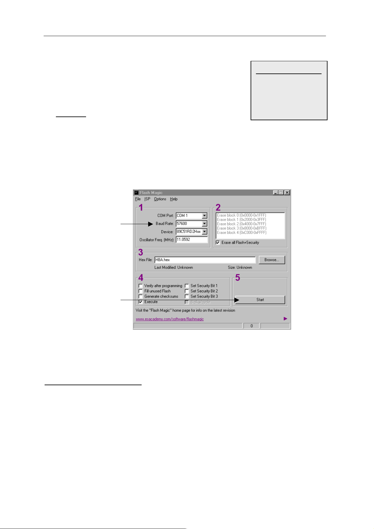
5.1.6 Firmware Update
Das Handbediengerät ist mit einem Flash-Programmspeicher
ausgerüstet. Dies erlaubt eine Änderung bzw. ein Update
der Firmware. Dazu wird die kostenlose Software
„Flash Magic“ V1.66 benötigt (siehe auch www.euchner.de).
-> durch die <Pfeiltasten>
-> ->
Klick Ein
Klick Ein
Klick Ein Klick Ein
->
-> ****Klick Aus
->->
Klick Aus
Klick AusKlick Aus
ENTER>
ENTER>ENTER>
Auswahl
Auswahl <ENTER>
AuswahlAuswahl
Es ist folgendermaßen vorzugehen:
1. Das HBAS ist über einen RS422-RS232 Schnittstellenwandler mit der seriellen
Schnittstelle des Rechners zu verbinden und an die Spannungsversorgung DC 24V
anzuschließen.
Firmware Update
Firmware Update
2. Um eine neue Version der Firmware in das
HBAS zu laden, muss das Handbediengerät in den
Programmiermodus gebracht werden.
Dazu wird im Konfigurationsmenü das
Firmwareupdate angewählt.
Verlassen des Fensters mit <ESC>.
Firmware Update Firmware Update
Zum Aktivieren
Zum Aktivieren
Zum Aktivieren Zum Aktivieren
Kommando senden
Kommando senden
Kommando senden Kommando senden
3. Die Software „Flash Magic“ muss gestartet werden.
095640-02-02/06 Technische Änderungen vorbehalten Seite 16 / 40
Page 17

EUCHNER Handbediengerät HBAS-094594
4. Zum Aktivieren des Übertragungsmodus muss nun
das Kommandowort „EUCO“ gesendet werden.
Kommandowort senden:
4e.
Im Pull-Down Menü von
„ISP“ Start BootROM
auswählen
4a.
Schnittstelle COMPort einstellen
Baud Rate 9600 einstellen
Device auswählen
Oscillator Freq. einstellen
4b.
Häkchen bei „Erase all
Flash+Security“ setzen
4c.
Position und Name des
HEX-Files angeben
4d.
Häkchen bei „Execute“
setzen
4f.
„Send Command“
auswählen
4g.
Kommando EUCO
eintragen und Baudrate
9600 auswählen
4h.
„Nothing“ auswählen
4i.
<Start BootROM> Button betätigen
Das Kommandowort
wird übertragen
095640-02-02/06 Technische Änderungen vorbehalten Seite 17 / 40
Page 18
EUCHNER Handbediengerät HBAS-094594
5. Wenn das Kommandowort korrekt empfangen
wurde, schaltet sich das HBAS in den Übertragungsmodus
(Text “ Bereit zur...“ wird angezeigt).
Die Status-LED erlischt.
Die Datenübertragung kann beginnen.
Achtung:
Befindet sich das Handbediengerät im Übertragungsmodus
muss eine Datenübertragung stattfinden. Danach wird das
Handbediengerät in den Normal-Modus zurückgesetzt.
Findet keine Übertragung statt, kann dieser Zustand nur von
der Fa. Euchner beseitigt werden.
5a.
Baud Rate auf 57600
ändern
Firmware Update
Firmware Update
Firmware Update Firmware Update
Bereit zur
Bereit zur
Bereit zur Bereit zur
Datenübertragung
Datenübertragung
DatenübertragungDatenübertragung
5b.
„Start“ Button betätigen
Die Datenübertragung
dauert ca. 45 Sekunden.
(20 Sek. für Flash löschen
und 25 Sek. für Flash
programmieren)
Danach beginnt das HBA
mit der Initialisierung.
5.2 Einstellen der Baudrate
Das Handbediengerät erkennt die Baudrate der Steuerung automatisch und stellt sich auf
diese ein. Mögliche Werte sind 9600 und 19200 Baud.
Diese automatische Einstellung erfolgt beim Initialisieren des Handbediengerätes (siehe
Kapitel 9). Eine Änderung der Baudrate kann nur erfolgen, wenn das Handbediengerät
kurzzeitig von der Spannungsversorgung getrennt wird. Bei der anschließenden neuen
Initialisierung wird das HBAS auf die neue Baudrate eingestellt.
095640-02-02/06 Technische Änderungen vorbehalten Seite 18 / 40
Page 19

EUCHNER Handbediengerät HBAS-094594
6. Signalmeldung
6.1 Akustische Signalmeldung (Befehlsbyte 52H)
Im Handbediengerät ist ein akustischer Signalgeber integriert. Dieser kann von der
Steuerung bedient werden. Dazu muss das Befehlsbyte 52H mit dem entsprechenden
Parameter gesendet werden.
Befehlsbyte Beschreibung Parameter:
52H
Dauerton Ein
Dauerton Aus
Tonintervall Ein (Frequenz 1Hz)
Tonimpuls 0,1s
30H
31H
32H
33H
Beispiel: Tonintervall einschalten
HBAS DLE DLE
Steuerung STX 52H 32H DLE ETX BCC
Wird ein falscher Parameter angegeben, wird das Fehlerbyte auf 34H gesetzt.
Das Fehlerbyte kann über die Statusabfrage abgefragt werden (siehe Kapitel 9).
6.2 Optische Signalmeldung: Status-LED
Die Status-LED signalisiert programminterne Informationen. Der Anwender hat keinen
Zugriff auf die Ansteuerung.
Folgende Informationen werden signalisiert:
Status-LED Funktion
Dauerlicht Datenübertragung aktiv
Blinken 0,5Hz Datenübertragung nicht aktiv, HBAS bereit zur Initialisierung
Blinken 2 Hz Handbediengerät im Konfigurationsmodus
Blinken 4 Hz
1)
Scheitert der Versuch vom HBAS die Verbindung zur Steuerung aufzubauen, oder wird
Fehler in der Kommunikation
1)
eine bestehende Verbindung unterbrochen (siehe Kapitel 3), so geht das
Handbediengerät in den Fehlerzustand und die Status-LED blinkt mit einer Frequenz
von 4 Hz.
095640-02-02/06 Technische Änderungen vorbehalten Seite 19 / 40
Page 20

EUCHNER Handbediengerät HBAS-094594
6.3 Optische Signalmeldung: Power-LED
Die Power-LED signalisiert die korrekte Spannungsversorgung.
Folgende Informationen werden angezeigt:
Power-LED Funktion
Aus Spannungswert zu niedrig
Blinken Spannungsversorgung im kritischen Bereich. keine Funktion
Dauerlicht Spannungsversorgung in Ordnung
7. Tastenänderung melden
Ist das Handbediengerät initialisiert und die Kommunikation mit der Steuerung aufgebaut,
wird beim Betätigen einer Taste das entsprechende Tastenbyte an die Steuerung
gesendet.
Tastenbyteübertragung beim gleichzeitigen Betätigen von mehreren Tasten:
Grundsätzlich wird immer die zuerst betätigte Taste übertragen.
Wenn zum Zeitpunkt der Betätigung bereits eine andere Taste betätigt ist, wird die zweite
Taste ignoriert, es erfolgt erst eine Zustandsänderung, wenn die zuerst betätigte Taste
losgelassen wird.
Wird zusätzliche eine dritte Taste betätigt, und dann die erste Taste losgelassen, so bleibt
die Tasteninformation der ersten Taste bestehen.
Steuerung HBAS
Byte 1 STX (02H)
Byte 1 DLE
Byte 2 TASTENBYTE (siehe Tastentabelle)
Byte 3 DLE (10H)
Byte 4 ETX (03H)
Byte 5 BCC
Byte 2 DLE
Beispiel: Taste S11 wird betätigt
HBAS STX 3BH DLE ETX BCC
Steuerung DLE DLE
Beispiel: Taste S11 wird losgelassen
HBAS STX 30H DLE ETX BCC
Steuerung DLE DLE
095640-02-02/06 Technische Änderungen vorbehalten Seite 20 / 40
Page 21

EUCHNER Handbediengerät HBAS-094594
Tastentabelle Tasten Layout
Tastennr. TASTENBYTE
Taste S 1 31H
Taste S 2 32H
Taste S 3 33H
Taste S 4 34H
Taste S 5 35H
Taste S 6 36H
Taste S 7 37H
Taste S 8 38H
Taste S 9 39H
Taste S 10 3AH
Taste S 11 3BH
Taste S 12 3CH
Taste S 13 3DH
Taste S 14 3EH
Taste S 15 3FH
Taste S 16 40H
Taste S 17 41H
Taste S 18 42H
Taste S 19 43H
Taste S 20 44H
keine Taste betätigt 30H
POWER STATUS
S1 S2 S3
S4 S5 S6 S7
S8 S9 S10 S11
S14 S15S12 S13
S18 S19S16 S17
S20
095640-02-02/06 Technische Änderungen vorbehalten Seite 21 / 40
Page 22
EUCHNER Handbediengerät HBAS-094594
8. Impulsgeberfunktion
Im Handbediengerät ist ein Impulsgeber integriert. Diese Funktion wird mit zwei frei
wählbaren Tasten realisiert. Die Festlegung erfolgt im Konfigurationsmenü
(siehe Kapitel 5.1.4).
Voreingestellt sind die Tasten . Die Freigabe des Impulsgebers erfolgt ebenfalls im
Konfigurationsmenü. Grundeinstellung ist: „aktiviert“.
Der Bediener hat die Möglichkeit, mit dem Betätigen einer der beiden Tasten Zählimpulse
an die Steuerung auszugeben. Als Ausgangsstufe wird ein RS422 Treiberbaustein
verwendet, der die Ausgangssignale A, /A, und B, /B beinhaltet (siehe technische Daten).
Wird die Taste (oder vom Kunden verändert)
kurz gedrückt, so wird 1 Zählimpuls
rechtsdrehend (CW) gesendet.
Bei Betätigung der Taste (oder vom Kunden
verändert) wird 1 Zählimpuls
linksdrehend (CCW) gesendet.
Wird eine der beiden Tasten länger als die eingestellte Verzögerungszeit (Umschaltung
von Einzelimpuls auf stetige Impulsfolge) gedrückt, so wird nach Ablauf dieser Zeit eine
Zählfrequenz der entsprechenden Richtung ausgegeben. Der Wert dieser Zeit und die
Frequenz werden im Konfigurationsmenü eingestellt (siehe Kapitel 5).
Beispiel: Taste für CW wird ca.2 Sekunden lang betätigt.
Eingestellte Verzögerungszeit = 500ms, eingestellte Zählfrequenz = 80 Hz.
Einzel-
impuls
4ms
Taste
betätigt
Verz.-
zeit
500ms
Zählfrequenz 80Hz
1500ms
Taste
losgelassen
095640-02-02/06 Technische Änderungen vorbehalten Seite 22 / 40
Page 23

EUCHNER Handbediengerät HBAS-094594
9. Initialisierung
Um die Kommunikationsschnittstelle freizugeben, muss das Handbediengerät initialisiert
werden.
Die Initialisierung erfolgt entweder durch das Abfragen der aktuellen Zustände der Tasten
mit der Funktion „Statusabfrage“, mit der Parameterübertragung (siehe Kapitel 9), oder mit
dem Senden eines sonstigen gültigen Befehlsbytes (siehe Kapitel 10.3 Befehlsübersicht).
Bei der Initialisierung wird auch die Baudrate eingestellt (siehe Kapitel 5).
9.1 Statusabfrage (Befehlsbyte 23H)
Der Zustand der Tasten und das Fehlerbyte können von der Steuerung zu jedem
beliebigen Zeitpunkt mit dem Befehlsbyte 23H abgefragt werden.
Das Fehlerbyte bleibt so lange gesetzt, bis eine Statusabfrage durchgeführt wird oder eine
weitere fehlerfreie Übertragung erfolgt.
Nach der Statusabfrage wird das Fehlerbyte auf 31H (kein Fehler) zurückgesetzt.
Es wird empfohlen, nach dem Empfang eines NAK Zeichens eine Statusabfrage zur
Initialisierung durchzuführen, da hierdurch das HBAS zurückgesetzt wird.
Die Steuerung fordert vom HBAS den aktuellen Status an
HBAS Steuerung
Byte 1 STX (02H)
Byte 1 DLE
Byte 2 STATUSWORT (23H)
Byte 3 DLE (10H)
Byte 4 ETX (03H)
Byte 5 BCC
Byte 2 DLE
Das HBAS sendet der Steuerung seinen aktuellen Status
Steuerung HBAS
Byte 1 STX (02H)
Byte 1 DLE
Byte 2 TASTENBYTE (siehe Kapitel 7)
Byte 3 FEHLERBYTE (siehe Kapitel 9)
Byte 4 DLE (10H)
Byte 5 ETX (03H)
Byte 6 BCC
Byte 2 DLE
Die Steuerung darf mit der Datenübertragung erst dann fortfahren, wenn das HBAS mit der
Statusübertragung fertig ist.
095640-02-02/06 Technische Änderungen vorbehalten Seite 23 / 40
Page 24

EUCHNER Handbediengerät HBAS-094594
Beispiel: Statusanforderung und Senden von Taste S11und Fehlerbyte 31H
Steuerung fordert
Status an
HBAS DLE DLE STX 3BH 31H DLE ETX BCC
Steuerung STX 23H DLE ETX BCC DLE DLE
HBA sendet Taste
und Fehlerbyte
Fehlerbytes
Wird bei einem Befehl, der eine Parameterangabe erfordert, ein falscher oder
unvollständiger Parameter übertragen, kann mit der Statusabfrage dieses Fehlerbyte
abgefragt werden. Das Fehlerbyte wird nach der Tasteninformation gesendet.
Folgende Fehlermeldungen sind möglich:
Fehler-
byte
31H
32H
33H
34H
35H
Fehler Erklärung
keine Fehler Störungsfreier Betriebszustand
Text nicht definiert
Bereich nicht definiert
Parameter ungültig
zu viele Parameter
Ein mit einem Kurzbefehl aufgerufener Text
wurde noch nicht definiert
Ein mit einem Kurzbefehl aufgerufener Bereich
wurde noch nicht definiert
Ein angegebener Parameter ist außerhalb des
gültigen Wertebereichs
Die Anzahl der angegebenen Parameter
entspricht nicht der erwarteten Anzahl
Ein aufgerufener Bereich überschneidet sich
36H
Bereich ungültig
mit einem Zeichen, das mit dem großen Font
dargestellt wird. (siehe Kapitel 10)
9.2 Konfigurations-Parameterübergabe (Befehlsbyte 53H)
Von der Steuerung können sämtliche Parameter, die im Konfigurationsmenü eingestellt
werden können, zu jedem beliebigen Zeitpunkt übertragen werden.
Dazu muss vor die Parameterdaten das Befehlsbyte 53H gesetzt werden.
Nachdem die Datenübertragung gestartet wurde, erlischt die STATUS-LED.
Das Display wird gelöscht und der Text „Par. speichern“ ausgegeben.
Als Quittierung für eine korrekte Datenspeicherung im Flash wird vom HBAS ein kurzer
Tonimpuls ausgegeben und der Text „Par. speichern wird gelöscht.
Wird ein Parameter nicht korrekt angegeben, so wird das Fehlerbyte „34H“ gesetzt. Das
Fehlerbyte kann durch die Steuerung über die Statusabfrage abgefragt werden.
095640-02-02/06 Technische Änderungen vorbehalten Seite 24 / 40
Page 25

EUCHNER Handbediengerät HBAS-094594
Folgende Reihenfolge der einzelnen Parameter muss zwingend eingehalten werden!
1. PIN
2. Kollisionspriorität
3. Tastenklick
4. Impulsgeberaktivierung
5. Impulsgeber-Tastenverzögerung (wenn Impulsgeber aktiv)
6. Impulsgebertaste CW (wenn Impulsgeber aktiv)
7. Impulsgebertaste CCW (wenn Impulsgeber aktiv)
8. Impulsgeberfrequenz (wenn Impulsgeber aktiv)
Wird die Impulsgeberfunktion nicht aktiviert, so brauchen die Impulsgeberparameter
„Impulsgeber-Tastenverzögerung“,
„Impulsgebertaste CW“,
„Impulsgebertaste CCW“
„Impulsgeberfrequenz“
nicht übertragen werden.
Parameter-
Nr.
1 PIN: 1000-er Stelle Nur Ziffern 0-9 im HEX-Format 30H ... 39H
2 PIN: 100-er Stelle Nur Ziffern 0-9 im HEX-Format 30H ... 39H
3 PIN: 10-er Stelle Nur Ziffern 0-9 im HEX-Format 30H ... 39H
4 PIN: 1-er Stelle Nur Ziffern 0-9 im HEX-Format 30H ... 39H
5 Kollisionspriorität:
6 Tastenklick
7 Impulsgeberaktivierung
8 Impulsgeber Verzög. Taste 1000-er Nur Ziffern 0-9 im HEX-Format 30H ... 39H
9 Impulsgeber Verzög. Taste 100-er Nur Ziffern 0-9 im HEX-Format 30H ... 39H
10 Impulsgeber Verzög. Taste 10-er Nur Ziffern 0-9 im HEX-Format 30H ... 39H
11 Impulsgeber Verzög. Taste 1-er Nur Ziffern 0-9 im HEX-Format 30H ... 39H
Erklärung Parameterwert
30H = Steuerung hat Priorität
31H = HBAS hat Priorität
30H = Tastenklick aus
31H = Tastenklick ein
30H = Impulsgeber nicht aktiv
31H= Impulsgeber aktiv
12 Impulsgeber Taste CW
13 Impulsgeber Taste CCW
14 Impulsgeber Freq. in Hz 100-er Nur Ziffern 0-9 im HEX-Format 30H ... 39H
15 Impulsgeber Freq. in Hz 10-er Nur Ziffern 0-9 im HEX-Format 30H ... 39H
16 Impulsgeber Freq. in Hz 1-er Nur Ziffern 0-9 im HEX-Format 30H ... 39H
Fehlerbyte:
31H: Parameter korrekt übertragen
34H: Parameterübertragung fehlerhaft
Alle Tasten außer S2 (32H), S7 (37H),
S16 (40H), und S20 (44H)
Alle Tasten außer S2 (32H), S7 (37H),
S16 (40H), und S20 (44H)
095640-02-02/06 Technische Änderungen vorbehalten Seite 25 / 40
Page 26

EUCHNER Handbediengerät HBAS-094594
Beispiel: Impulsgeber aktiv
Klick
Imp.-
Verz. Taste 1500 ms CW CCW Freq.121Hz
geb.
aktiv
Steuerung
HBAS
Bef.
Byte
STX 53H 36H 37H 38H 39H 30H 30H 31H 31H 35H 30H 30H 43H 42H 31H 32H 31H DLE ETX BCC
DLE DLE
PIN
Priori-
tät
Beispiel: Impulsgeber nicht aktiv
Klick
Imp.-
geb.
aktiv
Steuerung
HBAS
Bef.
Byte
STX 53H 36H 37H 38H 39H 30H 30H 30H DLE ETX BCC
DLE DLE
PIN
Priori-
tät
Standardparameter
Bei Auslieferung des Handbediengerätes sind die Parameter folgendermaßen eingestellt:
Parameter Wert
PIN 1234
Kollisionspriorität Steuerung
Tastenklick aus
Impulsgeberaktivierung ein
Impulsgeber-Tastenverzögerung 1000 ms
Impulsgebertaste CW -Taste
Impulsgebertaste CCW -Taste
Impulsgeberfrequenz 80 Imp./Sek.
095640-02-02/06 Technische Änderungen vorbehalten Seite 26 / 40
Page 27

EUCHNER Handbediengerät HBAS-094594
10. LCD-Anzeige
Das Display des Handbediengerätes wird im Textmodus betrieben. Zur Text-Anzeige muss
die Steuerung die Art der Darstellung und den Inhalt der Anzeige senden.
Häufig anzuzeigende Texte können nach der Initialisierung jederzeit zum HBAS übertragen
und dort in einem Datenspeicher (RAM) abgelegt werden. Diese Texte können dann
jeweils mit einem Kurzbefehl zur Anzeige gebracht werden (siehe Kapitel 10.2).
Ebenso können Bereiche definiert werden und diese mit Attributen belegt werden. Diese
Bereiche können dann ebenfalls mit einem Kurzbefehl angezeigt werden
(siehe Kapitel 10.2).
Ansteuerung LC-Display
Jeder LCD-Datenblock, der einen Befehl zur Displayansteuerung enthält, muss als erstes
Zeichen das LCD-Kennungsbyte besitzen.
Dieses ist festgelegt auf
In einem LCD-Datenblock können mehrere LCD-Befehle untergebracht sein, er darf aber
die Länge von 135 Byte nicht überschreiten.
Befehl zum LCD-Display:
Steuerung HBAS/LCD
Byte 1 STX (02H)
Byte 2 LCD-Datenblock
Byte 3 DLE (10H)
Byte 4 ETX (03H)
Byte 5 BCC
6CH.
Byte 1 DLE (10H)
Byte 2 DLE (10H)
Wichtig!
Es ist nicht erlaubt, einen Datenblock zu unterbrechen, der bereits mit DLE bestätigt
wurde.
Vor einem neuen Sendevorgang ist es notwendig, den Empfangsbuffer auf ein STX
vom HBAS zu überprüfen.
095640-02-02/06 Technische Änderungen vorbehalten Seite 27 / 40
Page 28

EUCHNER Handbediengerät HBAS-094594
10.1 Zeichensatz
ASCII-Zeichensatz von 80H ... FFH
0123456789ABCDEF
8 !“#$%&´()*+,- . /
9 0123456789: ;<=>?
A @ABCDEFGH I JKLMNO
B PQRSTUVWXYZ
C `abcdef gh i j k lmno
D pq rs t uvwxyz { ¦ } ~
E Зьйвдаезкли п о мДЕ
F ЙжЖфцтыщяЦЬш£ШЧƒ
[
\]^_
095640-02-02/06 Technische Änderungen vorbehalten Seite 28 / 40
Page 29

EUCHNER Handbediengerät HBAS-094594
10.2 LCD-Funktionen (Kennung 6CH)
10.2.1 Cursorfunktionen
Die Cursorsteuerung erfolgt durch das Senden eines Befehlsbytes und gegebenenfalls
durch das Senden zusätzlicher Parameter.
Befehlsbyte Beschreibung Parameter
21H
22H
23H
24H
25H
26H
Cursor zum nächsten Zeichen
Cursor zum vorhergehenden
Zeichen
Cursor eine Zeile runter
Cursor eine Zeile höher
Cursor an Displayanfang
Cursor an Zeilenanfang
kleiner Font:
27H
Cursor an bestimmte Position
Zeile (30H...37H), Spalte (30H...3FH)
großer Font:
Zeile (30H...33H), Spalte (30H...37H)
Beispiel: Cursor wird zuerst an den Displayanfang gesetzt und dann an die Zeile 2,Spalte 3
Steuerung STX 6CH 25H 27H 32H 33H ETX BCC
HBAS DLE DLE
10.2.2 Zeichenausgabe
Um ein Zeichen an der momentanen Cursorposition auszugeben, genügt es, dieses
Zeichen in den Datenblock zu schreiben. Der Cursor wird anschließend eine Position weiter
gesetzt (außer am Display-Ende). Am Zeilenende findet ein LF statt. An der letzten Zeile
an der letzten Position bleibt der Cursor stehen und schreibt an dieser Position den
verbleibenden Text.
Beispiel: An der aktuellen Cursorposition wird der Text „Euchner“ ausgegeben
Steuerung STX 6CH A5H D5H C3H C8H CEH C5H D2H ETX BCC
HBAS DLE DLE
095640-02-02/06 Technische Änderungen vorbehalten Seite 29 / 40
Page 30

EUCHNER Handbediengerät HBAS-094594
10.2.3 Text-Attribute
Über die entsprechenden Befehlsbytes können Texte mit verschiedenen Attributen
ausgegeben werden. Die gesetzten Attribute bleiben bis zum Zurücksetzen gültig.
Befehlsbyte Beschreibung Parameter
40H
41H
42H
43H
50H
51H
Invers ein: Alle nachfolgenden Zeichen werden invers
ausgegeben
Invers aus: Alle nachfolgenden Zeichen werden normal
ausgegeben
Blinken ein: Alle nachfolgenden Zeichen werden
blinkend ausgegeben
Blinken aus
Auswahl „kleiner Font“
Auswahl „großer Font“
Beispiel:
Inverse und blinkende Ausgabe von Text „Euchner“ mit großem Font an der aktuellen
Cursorposition. Danach Blinken und Invers wieder aus.
Steuerung STX 6CH 51H 40H 42H A5H D5H C3H C8H CEH C5H D2H 41H 43H ETX BCC
HBAS DLE DLE
Erläuterung zur Fontgröße:
Der Zeichensatz kann in 2 unterschiedlichen Fontgrößen dargestellt werden. Es können
Zeichen in beiden Fontgrößen gleichzeitig dargestellt werden.
Wenn die Fontgröße wechselt, wird der Cursor automatisch an den Displayanfang gesetzt.
Kleiner Font: Das Display ist aufgeteilt in 8 Zeilen und 16 Zeichen. Das einzelne
Zeichen besteht aus 8x8 Pixel.
Großer Font: Das Display ist aufgeteilt in 4 Zeilen und 8 Zeichen. Das einzelne
Zeichen besteht aus 16x16 Pixel und ist somit doppelt so groß wie
der kleine Font.
095640-02-02/06 Technische Änderungen vorbehalten Seite 30 / 40
Page 31

EUCHNER Handbediengerät HBAS-094594
10.2.4 Löschbefehle
Befehlsbyte Beschreibung Parameter
28H
29H
2AH
Löschen an aktueller Cursorposition
Löschen bis Zeilenende
Löschen bis Display-Ende
2)
3)
2BH Löschen des gesamten Displays
Löschen eines Displaybereichs
2CH
(Es werden unabhängig der Fontgröße immer 8 Zeilen und 16 Spalten
zugrunde gelegt)
1)
Nach dem „Löschen an aktueller Cursorposition“ verbleibt der Cursor auf der gleichen
Position.
2)
Nach dem „Löschen bis Zeilenende“ verbleibt der Cursor am Zeilenende.
3)
Nach dem „Löschen bis Display-Ende“ verbleibt der Cursor am Display-Ende.
4)
Nach dem „Löschen des gesamten Displays“ befindet sich der Cursor am Displayanfang
5)
Nach dem „Löschen eines Displaybereichs“ befindet sich der Cursor rechts unten vom
1)
4)
5)
Startzeile (30H...37H),
Startspalte (30H...3FH),
Endezeile (30H...37H),
Endespalte (30H...3FH)
gelöschten Bereich.
Beispiel: Löschen von aktueller Cursorposition bis zum Zeilenende
Steuerung STX 6CH 29H ETX BCC
HBAS DLE DLE
Beispiel: Löschen von Spalte 2, Zeile 3 bis Spalte 12, Zeile 6
Steuerung STX 6CH 2CH 32H 33H 3CH 36H ETX BCC
HBAS DLE DLE
10.2.5 Textbefehle
Der Anwender kann bis zu 200 verschiedene Texte und deren Bildschirmposition definieren
und diese dann mit einem Kurzbefehl zur Anzeige bringen. Ein Text darf dabei maximal 30
Zeichen lang sein.
Die Textdefinitionen können jederzeit durchgeführt werden. Wird ein bereits definierter Text
neu definiert, so wird der alte Text gelöscht. Innerhalb eines definierten Textes sind auch
weitere LCD-Befehle zulässig, so dass längere Befehlsfolgen auch über diesen Kurzbefehl
aufrufbar sind (Makrofunktion).
Soll ein Text ausgegeben werden, der noch nicht definiert wurde, so wird das Fehlerbyte
34H gesetzt. Das Fehlerbyte kann über die Statusabfrage abgefragt werden
(siehe Kapitel 9).
095640-02-02/06 Technische Änderungen vorbehalten Seite 31 / 40
Page 32

EUCHNER Handbediengerät HBAS-094594
Befehlsbyte Beschreibung Parameter
Textnummer (31H...F9H),
Fontgröße (50H o.51H),
48H
Definition eines Textes
Zeile (siehe Tabelle unten),
Spalte (siehe Tabelle unten),
Text: (21H...2C),(40H...43H), (80H...FFH)
49H
Ausgabe eines zuvor
definierten Textes
Textnummer (31H...F9H)
Wichtig!
Die Zeilen- und Spaltenangabe ist abhängig von der Fontgröße!
Fontgröße Zeile Spalte
klein
groß
30H ... 37H 30H ... 3FH
30H ... 33H 30H ... 37H
Beispiel: Definition von Text „Euchner“ mit kleinem Font in Zeile 4 Spalte 0 als Text-Nr.5
Reihenfolge von Text und gesendeten Zeichen einhalten
Steuerung STX 6CH 48H 35H 50H 34H 40H A5H D5H C3H C8H CEH C5H D2H ETX BCC
HBAS DLE DLE
Beispiel: Anzeige von Text-Nr.5
Steuerung STX 6CH 49H 35H ETX BCC
HBAS DLE DLE
Beispiel: Blinkende Anzeige von Text-Nr.5
Steuerung STX 6CH 42H 49H 35H 43H ETX BCC
HBAS DLE DLE
Beispiel: Definition von „Display löschen“ und Text „EUCO“ mit kleinem Font, inverse
Darstellung, am Displayanfang als Text-Nr.6
Steuerung STX 6CH 48H 36H 50H 30H 30H 2BH 40H A5H B5H A3H AFH 41H ETX BCC
HBAS DLE DLE
095640-02-02/06 Technische Änderungen vorbehalten Seite 32 / 40
Page 33

EUCHNER Handbediengerät HBAS-094594
10.2.6 Bereichsbefehle
Der Anwender kann bis zu 32 Bereiche definieren, die er dann mit Kurzbefehlen löschen,
invertieren, blinkend darstellen oder normal darstellen kann. Das ansonsten gültige Attribut
wird nicht geändert.
Befehlsbyte Beschreibung Parameter
Bereichsnummer (31H...51H),
Startzeile (30H...37H),
4AH
4BH
Definition eines Bereiches
Löschen eines zuvor definierten
Bereiches
Startspalte (30H...3FH),
Endezeile (30H...37H),
Endespalte (30H...3FH)
Bereichsnummer (31H...51H)
4CH
4DH
4EH
4FH
Wichtig: Die Zeilen- und Spaltenangabe ist unabhängig von der Fontgröße!
Die Bereichsnummern gehen von 31H (Bereich 1) bis 51H (Bereich 32).
Wird ein nicht definierter Bereich angesprochen, so wird das Fehlerbyte 33H gesetzt.
Das Fehlerbyte kann über die Statusabfrage abgefragt werden und wird nach der Abfrage
auf 31H zurückgesetzt (siehe Kapitel 9).
Achtung:
Beim Aufruf eines definierten Bereiches darf es zu keiner Überschneidung zwischen den
Bereichsgrenzen und des Zeichens eines großen Fonts kommen. Ist dies der Fall, wird der
Befehl nicht ausgeführt und das Fehlerbyte 36H wird gesetzt. Das Fehlerbyte kann über
die Statusabfrage abgefragt werden und wird nach der Abfrage auf 31H zurückgesetzt.
Beispiel
Inverse Darstellung eines Bereiches
Blinkende Darstellung eines
Bereiches
Inv. + blinkende Darstellung eines
Bereiches
Normale Darstellung eines Bereiches
großer Fonts
Bereichsnummer (31H...51H)
Bereichsnummer (31H...51H)
Bereichsnummer (31H...51H)
Bereichsnummer (31H...51H)
Bereich:
31H, 31H, 32H, 3EH
(Zeile 1 bis 2 und
Spalte 1 bis 14)
E U C HNER
Falsch !
Richtig !
E
095640-02-02/06 Technische Änderungen vorbehalten Seite 33 / 40
U C HNER
Page 34

EUCHNER Handbediengerät HBAS-094594
Beispiel: Bereich Nr.22 definieren von Zeile 4 / Spalte 0 bis Zeile 6 / Spalte 10
Steuerung STX 6CH 4AH 46H 34H 30H 36H 3AH ETX BCC
HBAS DLE DLE
definierter
Bereich
Beispiel: Bereich Nr.22 löschen
Steuerung STX 6CH 4BH 46H ETX BCC
HBAS DLE DLE
Beispiel: Bereich Nr.22 blinkend anzeigen
Steuerung STX 6CH 4DH 46H ETX BCC
HBAS DLE DLE
095640-02-02/06 Technische Änderungen vorbehalten Seite 34 / 40
Page 35

EUCHNER Handbediengerät HBAS-094594
10.3 Befehlsübersicht
Kennungs-
byte
6CH
Befehls-
byte
21H Cursor zum nächsten Zeichen
22H Cursor zum vorhergehenden Zeichen
23H Cursor eine Zeile tiefer
24H Cursor eine Zeile höher
25H Cursor an Displayanfang
26H Cursor an Zeilenanfang
27H Cursor an bestimmte Position Zeile, Spalte
28H Löschen an aktueller Cursorposition
29H Löschen bis Zeilenende
2AH Löschen bis Display-Ende
2BH Löschen des gesamten Displays
2CH Löschen eines Bildschirmbereichs
40H
41H Invers aus
42H
43H Blinken aus
08H Definition eines Textes
49H Ausgabe eines zuvor definierten Textes Textnummer
4AH Definition eines Bereiches
4BH Löschen eines zuvor definierten Bereiches Bereichsnummer
4CH Inverse Darstellung eines Bereiches Bereichsnummer
4DH Blinkende Darstellung eines Bereiches Bereichsnummer
4EH Inv. + blinkende Darstellung eines Bereiches Bereichsnummer
4FH Normale Darstellung eines Bereiches Bereichsnummer
50H
51H
80H ... FFH ASCII-Zeichensatz
23H
Beschreibung Parameter
Startzeile, Startspalte,
Endezeile, Endespalte
Invers ein: Alle nachfolgenden Zeichen werden
invers ausgegeben
Blinken ein: Alle nachfolgenden Zeichen
werden blinkend ausgegeben
Textnummer, Fontgröße,
Zeile, Spalte, Text
Bereichsnummer, Startzeile,
Startspalte, Endezeile,
Endespalte
Auswahl „kleiner Font“
Auswahl „großer Font“
Statusabfrage (Tasten 30H ... 44H und
Fehlerbyte 31H ... 36H werden gesendet)
30H
31H
32H
33H
Impulsgeber aktiv,
Tastenbelegung,
Tastenklick
ohne
Dauerton Ein
52H
53H Parametereinstellungen übertragen
Dauerton Aus
Tonintervall Ein
Tonimpuls 0,5s
PIN, Kollisionspriorität,
Verz. Taste Impulsgeber,
Impulsgeberfrequenz,
095640-02-02/06 Technische Änderungen vorbehalten Seite 35 / 40
Page 36

EUCHNER Handbediengerät HBAS-094594
11. Installationshinweise
Die Einhaltung der für die EUCHNER – Handbediengeräte spezifizierten
EMV-Vorschriften setzt voraus, dass die Anschlussleitungen in abgeschirmter Ausführung
verwendet werden.
Die Abschirmung der Handbediengeräteleitung ist auf dem Steckergehäuse aufgelegt.
Kundenseitig ist eine Metall-Flanschdose zu montieren und deren Gehäuse elektrisch
leitend, niederohmig und induktionsarm zu erden.
Von dort aus weitergeführte Leitungen zur Kommunikationsschnittstelle und zur
Weiterbehandlung der Impulsgebersignale sind ebenfalls geschirmt auszuführen und der
Schirm an einem geeigneten Erdungspunkt an der Steuerung anzuschließen.
Als Installationszubehör steht eine Flanschdose zur Verfügung
Für die Kommunikationsschnittstelle ist ein RS 422A-Senderbaustein und ein RS 422AEmpfängerbaustein vorzusehen.
Für die Impulsgebersignale ist steuerungsseitig ein RS422A-Empfängerbaustein
vorzusehen.
12. Technische Daten: Impulsgeber
Impulsgeber
Ausgangsstufe RS 422A
auf der Steuerungsseite ist ein
Anschluss
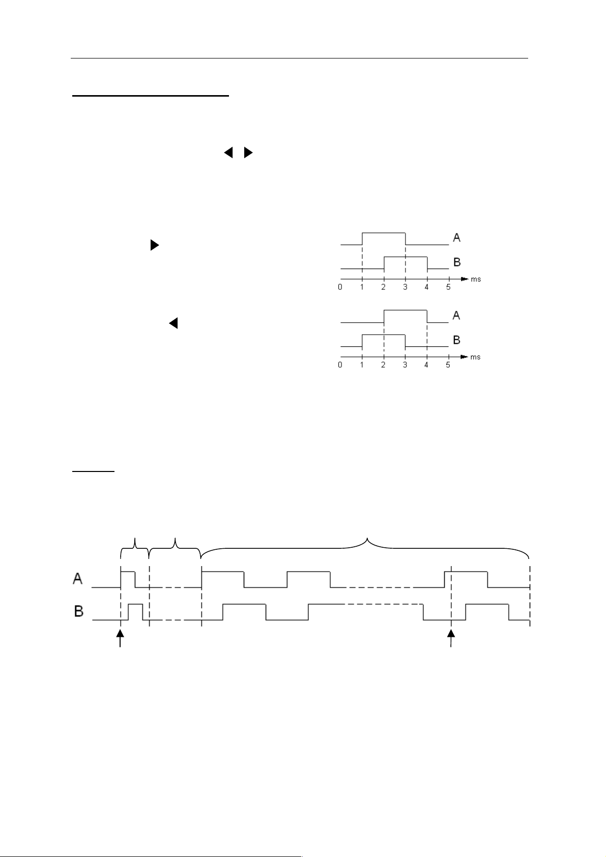
Impulsdiagramm für aufsteigendes Zählen,
cw (rechtsdrehend im Uhrzeigersinn)
Impulsdiagramm für absteigendes Zählen,
ccw (linksdrehend entgegen dem
Uhrzeigersinn)
entsprechender
RS422Empfängerbaustein zu verwenden
90°
90°
360°
A
A
B
B
Ruhelage
360°
A
A
B
B
Ruhelage
Empfänger
in der Steuerung
RS422
RS422
Treiberanordnung
Sender
im HBAS
RS422
RS422
A
A
B
B
095640-02-02/06 Technische Änderungen vorbehalten Seite 36 / 40
Page 37

EUCHNER Handbediengerät HBAS-094594
13. Technische Daten: allgemein
Parameter
Gehäusewerkstoff Polycarbonat
Farbe Grau RAL 7040
Betriebstemperatur 0 °C bis +50 °C
Lagertemperatur -20 °C bis +50 °C
Luftfeuchtigkeit, rel., max. 80 %, Betauung unzulässig
Schutzart nach EN60529 / IEC529
NEMA
Masse 860 g
Widerstandsfähigkeit gegenüber Vibrationen
Schwingungen (3 Achsen)
Schock (3 Achsen)
EMV-Schutzanforderungen gemäß CE
IP 65
250-12
DIN/IEC 68-2-6
DIN/IEC 68-2-27
EN 61000-6-2
EN 61000-6-4
Betrieb nur
mit UL-Class 2 Spannungsversorgung
Elektrischer Anschluss
Betriebsspannung UB DC 24 V ± 20%
Betriebsstrom, max. 100 mA
Kommunikations-Schnittstelle
Typ seriell, RS 422A (4-Draht)
Datenformat
Übertragungsgeschwindigkeit
Übertragungsprotokoll Prozedur 3964 R
Speicher
Programmspeicher (Firmware) Flash, 64 kByte
Datenspeicher für Texte RAM, 32 kByte, flüchtig
NOT-AUS
Norm EN418
Schaltelement 2 Öffner
Gebrauchskategorie nach IEC 947-5-1 DC-13 Ue=30 V / Ie=3 A
Zustimmtaster 3-stufig
Schaltelement 2 Schließer
Gebrauchskategorie nach IEC 947-5-2 DC-13 Ue = 24 V / Ie = 0,1 A
Schaltstrom, max. 0,1A
Schaltstrom, min. 5 mA
Schaltleistung, max. 250 mW
8 Datenbits + 1 Paritätsbit (gerade),
1 Stop-Bit
9 600 oder 19 200 Baud,
automatische Erkennung
Sonstige Komponenten des HBAS siehe Katalog EUCHNER Handbediengeräte
095640-02-02/06 Technische Änderungen vorbehalten Seite 37 / 40
Page 38

EUCHNER Handbediengerät HBAS-094594
Zubehör
Flanschdose 19-polig
Halter
Active-X-Modul
Demo- und Testsoftware im Internet verfügbar unter www.euchner.de
095640-02-02/06 Technische Änderungen vorbehalten Seite 38 / 40
Page 39

EUCHNER Handbediengerät HBAS-094594
095640-02-02/06 Technische Änderungen vorbehalten Seite 39 / 40
Page 40

EUCHNER GmbH + Co. KG Telefon 0711 / 75 97 - 0
Kohlhammerstraße 16 Telefax 0711 / 75 33 16
D-70771 Leinfelden-Echterdingen www.euchner.de . info@euchner.de
Page 41

Hand-Held Pendant Station
with Display
HBAS 094594
Manual
Page 42

EUCHNER Hand-Held Pendant Station HBAS-094594
Table of contents
1. Mechanical dimensions and Pin assignment ..................................................................... 3
1.1 Mechanical dimensions................................................................................................................. 3
1.2 Pin assignment ............................................................................................................................. 4
2. Features ............................................................................................................................ 5
3. Data transfer...................................................................................................................... 7
3.1 Protocol 3964 R ............................................................................................................................ 7
3.2 Definition of the characters ........................................................................................................... 8
3.3 BCC Block Check Character ........................................................................................................ 9
3.4 Examples for the determination of the BCC ................................................................................. 9
4. Priorities on a data collision ............................................................................................. 11
5. Behavior on switch on / initialization ................................................................................ 13
5.1 Configuration (Konfiguration) menu ............................................................................................ 13
5.1.1 Change PIN (PIN ändern)...................................................................................................... 14
5.1.2 Priority (Priorität).................................................................................................................... 14
5.1.3 Version information (Versionsabfrage) .................................................................................. 14
5.1.4 Pulse generator (Impulsgeber) .............................................................................................. 14
5.1.5 Key click (Tasten-Klick) ......................................................................................................... 16
5.1.6 Firmware Update ................................................................................................................... 16
5.2 Setting the baud rate................................................................................................................... 18
6. Signaling.......................................................................................................................... 19
6.1 Acoustic signaling (command byte 52H) .................................................................................... 19
6.2 Optical signaling: Status LED .................................................................................................... 19
6.3 Optical signaling: Power LED .................................................................................................... 20
7. Signaling a key change.................................................................................................... 20
8. Pulse generator function.................................................................................................. 22
9. Initialization...................................................................................................................... 23
9.1 Status polling (command byte 23H)............................................................................................ 23
9.2 Configuration parameter transfer (command byte 53H) ............................................................. 24
10. LC display...................................................................................................................... 27
10.1 Character set ............................................................................................................................ 28
10.2 LCD functions (identifier 6CH) .................................................................................................. 29
10.2.1 Cursor functions................................................................................................................... 29
10.2.2 Character output .................................................................................................................. 29
10.2.3 Text attributes ...................................................................................................................... 30
10.2.4 Clear commands ................................................................................................................. 31
10.2.5 Text commands ................................................................................................................... 31
10.2.6 Area commands .................................................................................................................. 33
10.3 Overview of commands ............................................................................................................ 35
11. Installation instructions .................................................................................................. 36
12. Technical Data: Pulse generator.................................................................................... 36
13. Technical Data: General................................................................................................ 37
095640-02-02/06 Subject to technical modifications Page 2 / 40
Page 43

EUCHNER Hand-Held Pendant Station HBAS-094594
1. Mechanical dimensions and Pin assignment
1.1 Mechanical dimensions
160
S1
S2
Ø 85
39,0
Mounting magnet
700550 -2500
3500 (cable length extended)
plug connector
19 pin
095640-02-02/06 Subject to technical modifications Page 3 / 40
Page 44

EUCHNER Hand-Held Pendant Station HBAS-094594
1.2 Pin assignment
screen electrically connected
to the plug housing
WH
BN
RDBU
0,14²
0,14²
0,14²
1
2
12
Display
Keyboard
Displaymemory
RAM
Power
supply
Shield
0 V
+24 V
X1:2
X1:3
X2:3
X2:2
POWER STATUS
Micro-
controller
Program-
memory
FLASH
Emergency-stop
A
A
B
RS422
B
Pulse generator
Interface
RX
RX
TX
TX
Communication
Interface RS422
S1
12
12
X2:5
X2:6
X2:1
X2:4
X1:6
X1:4
X1:1
X1:5
S1-a1
S1-b1
S1-b2
S1-a2
GN
YE
GY
PK
BU
RD
BK
VT
GYPK
GNWH
BNGN
WHYE
0,14²
0,14²
0,14²
0,14²
0,14²
0,14²
0,14²
0,14²
0,14²
0,14²
0,14²
0,14²
3
4
5
6
7
8
9
10
11
13
14
15
16
18
19
17
E1
E2
E1
E2
Contacts
open
closed
Trigger point
a
b
1
a
b
3
2
Enabling
switch left
132
S2
E1
E2
3
3
4
4
X3:3
X3:2
X3:4
X3:1
YEBN
BNGY
WHPK
GYWH
0,14²
0,14²
0,14²
0,14²
not connected:
BNPK
BUWH
BNBU
RDWH
0,14²
0,14²
0,14²
0,14²
095640-02-02/06 Subject to technical modifications Page 4 / 40
Page 45

EUCHNER Hand-Held Pendant Station HBAS-094594
2. Features
Housing of Hand-Held Pendant Station
Plastic housing made of polycarbonate, color gray RAL 7040,
with mounting magnet on the rear of the device
Keypad
Membrane keypad made of polyester
with window for LC display, 20 keys and 2 LEDs
095640-02-02/06 Subject to technical modifications Page 5 / 40
Page 46

EUCHNER Hand-Held Pendant Station HBAS-094594
Switching elements / display elements
On the membrane keypad there are 20 keys with labels, as well as a green POWER
LED and a green STATUS LED.
The EMERGENCY STOP device is on the top of the device and has rotary
unlocking according to EN 418 with 2 normally closed contacts.
A dual-channel version of a three-stage enabling switch is integrated in the left side
panel (see chapter 1.2 Pin assignment).
Display
Gray LC display with LED background lighting
128 x 64 dots, text operating mode
Window: 45.2 x 27.0 mm (W x H)
Pixel size: 0.28 mm x 0.34 mm (W x H)
Small font: Large font:
Character size: 2.2 mm x 2.62 mm Character size: 4.44 mm x 5.28 mm
16 characters per line, 8 lines 8 characters per line, 4 lines
2,62 mm
2,22 mm
5,28 mm
4,44 mm
Device connection
The hand-held pendant station is connected using a 3.5 m spiral cable and a 19-pin
round plug connector with pin contacts.
The cross-section of all cores is 0.14 mm².
The related flange socket is available as an accessory.
095640-02-02/06 Subject to technical modifications Page 6 / 40
Page 47

EUCHNER Hand-Held Pendant Station HBAS-094594
3. Data transfer
3.1 Protocol 3964 R
The protocol for the serial interface corresponds to the procedure 3964 (R).
The data transfer is initiated by sending an STX character. The receiver must answer with
a DLE character within the stipulated acknowledgement delay of 500 ms.
The transmitter then switches to send mode.
If the receiver answers with NAK, a character <> DLE, with an incomplete character, or the
acknowledgement delay elapses, then the attempt to establish the connection has failed.
After three unsuccessful attempts, the transmitter interrupts the procedure and outputs an
error message to the higher level program.
If the connection is successfully established (receiver answers with DLE within the
acknowledgment delay), then the characters in the send buffer are sent to the receiver.
The receiver expects the data within a character delay of 128 ms. If this delay is not met,
the receiver sends an NAK character.
The transmitter then tries again to send the message.
After three unsuccessful attempts, the transmitter interrupts the procedure and outputs an
error message to the higher level program.
After the content of the buffer has been sent, the transmitter adds DLE and ETX as an end
marker. Then the BCC (Block Check Character) is sent. The receiver must confirm correct
reception with DLE within the acknowledgement delay, or indicate erroneous transfer
with NAK.
095640-02-02/06 Subject to technical modifications Page 7 / 40
Page 48

EUCHNER Hand-Held Pendant Station HBAS-094594
3.2 Definition of the characters
Character format: 8 bits
Value range: 00H ... FFH
The value range is divided up as follows:
Value range Function Transfer direction
00H ... 1FH General control character for protocol
30H ... 44H
20H ... 53H
80H ... FFH
Control characters:
Control
character
STX
ETX
DLE
NAK
BCC
Key code for the keys 1 to 20 and error
bytes
Control character or commands for the
LC display, the pulse generator and the
transfer of configuration parameters
Character set for the LC display
(see section Character set)
Value Function Explanation
02H Start of Text
03H End of Text
10H Data Link Escape Data transfer switch over
15H
Is calculated,
(section 3.3)
Negative
Acknowledge
Block Check
Character
HBAS Control
system
HBAS Control
system
Control system
HBAS
Control system
HBAS
Start of the character string
to be sent
End of the character string
to be sent
Negative response
Block check character for
checking correct data transfer
095640-02-02/06 Subject to technical modifications Page 8 / 40
Page 49

EUCHNER Hand-Held Pendant Station HBAS-094594
3.3 BCC Block Check Character
The BCC (Block Check Character) is defined by calculation.
During this process an EXCLUSIVE-OR operator is applied to all characters after STX.
The result is added at the end as the BCC character.
XOR operator
STX
Calculation:
XOR 2nd character in the data block
XOR nth character in the data block
XOR last character in the data block
XOR DLE
XOR ETX
= BCC
Simplification:
As the 2 special characters ETX and DLE are always present, these can be combined and
calculated separately to the actual data block.
The result for the data block is the subjected to an
EXCLUSIVE-OR operation with the constant 13H.
Data block DLE ETX BCC
1st character in the data block
03H XOR 10H = 13H
BCC = (XOR data block) XOR 13H.
3.4 Examples for the determination of the BCC
Example 1: The HBAS sends the key 7 (37H):
Byte 1 STX
Byte 2 37H (37H)
Byte 3 DLE (10H)
Byte 4 ETX (03H) XOR operator
Byte 5 BCC
37H XOR 10H = 27H
27H XOR 03H = 24H
Simplification by combining DLE and ETX :
37H XOR 13H = 24H
095640-02-02/06 Subject to technical modifications Page 9 / 40
Page 50

EUCHNER Hand-Held Pendant Station HBAS-094594
Example 2: The text "Euchner" is output on the display at the current cursor
position:
Euchner
HBAS
Control
system
STX 6CH A5H D5H C3H C8H CEH C5H D2H DLE ETX BCC ETX
DLE DLE
Byte 1 STX
Byte 2 6CH LCD identifier byte
Byte 3 A5H
Byte 4 D5H
Byte 5 C3H
Byte 6 C8H
Euchner
Byte 7 CEH
Byte 8 C5H
Byte 9 D2H
Byte 10 DLE (10H)
Byte 11 ETX (03H)
Byte 12 BCC (formed across bytes 2 to 11)
Calculation:
6CH XOR A5H = C9H Byte 2 XOR Byte 3
C9H XOR D5H = 1CH XOR Byte 4
XOR operator
1CH XOR C3H = DFH XOR Byte 5
DFH XOR C8H = 17H XOR Byte 6
17H XOR CEH = D9H XOR Byte 7
D9H XOR C5H = 1CH XOR Byte 8
1CH XOR D2H = CEH XOR Byte 9
CEH XOR 10H = DEH XOR Byte 10
DEH XOR 03H = DDH XOR Byte 11
BCC = DDH
Simplification by combining DLE and ETX :
6CH XOR A5H XOR D5H XOR C3H XOR C8H XOR CEH XOR
C5H XOR D2H = CEH
CEH XOR 13H = DDH
095640-02-02/06 Subject to technical modifications Page 10 / 40
Page 51

EUCHNER Hand-Held Pendant Station HBAS-094594
4. Priorities on a data collision
The term data collision is used when a user receives an STX character while the
user itself is trying to send an STX character. I.e. both users are sending the STX
character at the same time.
To negotiate this data collision, the behavior of the HBAS on the occurrence of a collision
can be set.
Either the hand-held pendant station has priority, that is the HBAS sends its data first and
then receives the data from the control system, or the control system has priority and the
data from the control system are received first and then the data sent to the control system.
This setting is set either in the Configuration (Konfiguration) menu (see section 5) or
as a parameter using parameter transfer (section 9).
Priority: "Control system"
The transmitter in the control system has high priority.
The transmitter in the HBAS has lower priority.
In the case of a data collision, this means that the HBAS detects an STX character when it
is also sending an STX to the control system, it interrupts its transfer and first receives the
data from the control system.
The data transfer to the control system is then repeated.
Example of a possible collision:
HBAS sends a key change STX DLE ??
The control system sends "LCD text" STX DLE ??
Solution:
First the control system sends and then the HBAS sends
HBAS STX DLE DLE STX 31H DLE ETX BCC
Control
system
STX 6CH 25H DLE ETX BCC DLE DLE
Priority: "HBAS"
The transmitter in the HBAS has high priority.
The transmitter in the control system has lower priority.
In the case of a data collision when the HBAS detects an STX character while it is
also sending an STX character, the control system must also detect the collision and
acknowledge the data transfer initiated by the HBAS with a DLE character. Only after
the successful completion of the data transfer, the control system can start its data
transfer.
095640-02-02/06 Subject to technical modifications Page 11 / 40
Page 52

EUCHNER Hand-Held Pendant Station HBAS-094594
Example of a possible collision:
HBAS sends a key change STX ??
The control system sends "LCD text" STX ??
Solution:
First the HBAS sends then the control system sends
HBAS STX 31H DLE ETX BCC DLE DLE
Control
system
STX DLE DLE STX 6CH 25H DLE ETX BCC
Structure chart send/receive routine for the control
Check input buffer for new character
If receive new character
then else
Send STX
Wait for new character
call Receive routine
Start new
transfer routine
If new character = DLE
then else
If new character = STX
then else
Send data
Wait for new character
If new character = DLE
then else
Send NAK
Send data
call Status check
Send NAK
call Status check
Status checkReceive routine
Check input buffer for new character
If receive new character
then
If new character = STX
then
Send DLE
Receive data block
Check BCC
If BCC = ok
Send DLE
Send NAKEvaluate key change +
error byte
else
else
exit sub
Send NAK
elsethen
Send status request (#)
Wait for status information
Evaluate status
095640-02-02/06 Subject to technical modifications Page 12 / 40
Page 53

EUCHNER Hand-Held Pendant Station HBAS-094594
5. Behavior on switch on / initialization
Immediately after the power supply is switched on, the HBAS is in an initial passive state.
The hand-held pendant station performs a self-test; this takes approx. 7 seconds.
After the self-test, a short sound is emitted and for 5 seconds it is possible to open the
Configuration (Konfiguration) menu using the <ENTER> key. The serial communication
interface is activated when this period has elapsed.
The EUCHNER LOGO is shown on the display and initialization by the control system
is awaited.
Until the initialization (see section 9) has been performed, all key operations are ignored.
5.1 Configuration (Konfiguration) menu
On the Configuration (Konfiguration) menu all parameters, that enable the hand-held
pendant station to be configured to meet specific requirements, can be changed manually.
It takes approx. 5 seconds to save a parameter change. The successful application of the
new parameters is confirmed by a short sound.
The Configuration (Konfiguration) menu is protected with a PIN. (Default setting on delivery
"1234").
The serial communication interface is shut down.
After the power supply is switched on, the text "Configure hand-held pendant station,
<ENTER>“ (Handbediengerät konfigurieren, <ENTER>) appears after the self-test.
The user now has 5 seconds to open the menu using the <ENTER> key.
After <ENTER> is pressed, a prompt for the PIN is displayed. A PIN with a maximum of
4 digits is to be entered. The exception here is the SuperPIN (151050) with 6 digits; this
PIN cannot be changed. It is possible to delete a character using the key.
The following settings are now possible:
Change PIN (PIN ändern) (section 5.1.1)
Priority (Priorität) (section 5.1.2)
Version information (Versionsabfrage) (section 5.1.3)
Pulse generator (Impulsgeber) (section 5.1.4)
Key click (Tasten-Klick) (section 5.1.5)
Firmware Update (section 5.1.6)
A selection is made using the keys, the selection is confirmed using <ENTER>.
The Configuration (Konfiguration) menu is left using the <ESC> key.
KONFIGURATION:
KONFIGURATION:
KONFIGURATION:KONFIGURATION:
Pin ändern
Pin ändern
Pin ändernPin ändern
Priorität
Priorität
Priorität Priorität
095640-02-02/06 Subject to technical modifications Page 13 / 40
Page 54

EUCHNER Hand-Held Pendant Station HBAS-094594
5.1.1 Change PIN (PIN ändern)
The Configuration (Konfiguration) menu is protected
with a PIN. The hand-held pendant station is supplied
as standard with the PIN: "1234". This PIN should be
changed by the customer to protect the configuration
settings for the hand-held pendant station.
Only the numbers 0-9 can be entered.
A digit is deleted using the key.
An entry is accepted using <ENTER>.
Entry is cancelled using <ESC>.
The PIN must be confirmed a 2nd time.
5.1.2 Priority (Priorität)
If the HBAS and the control system send STX
at the same time, the term collision is used.
It must be defined which end has priority.
Select using the arrow ->
and accept using the <ENTER> key.
Leave the window with <ESC>.
The setting currently saved is marked by
* (asterisk).
the
-> with the <arrow keys>
->->
PIN ändern
PIN ändern
PIN ändern PIN ändern
Neue PIN:
Neue PIN:
Neue PIN: Neue PIN:
****
****
**** ****
PIN ändern
PIN ändern
PIN ändern PIN ändern
PIN bestätigen
PIN bestätigen
PIN bestätigen PIN bestätigen
****
****
**** ****
Priorität
Priorität
PrioritätPriorität
****HBA
->
Auswahl
Auswahl <ENTER>
Auswahl Auswahl
HBA
HBAHBA
-> Steuerung
Steuerung
->->
Steuerung Steuerung
<ENTER>
<ENTER><ENTER>
5.1.3 Version information (Versionsabfrage)
The current firmware version and the related date
are displayed in this window.
Leave the window with <ESC>.
5.1.4 Pulse generator (Impulsgeber)
The following functions can be selected on the
Pulse generator (Impulsgeber) menu:
• Activation (Aktivierung)
• Delay (Verzögerung Taste)
• Key assignment (Tastenbelegung)
• Frequency (Frequenz)
Select using the <arrow keys> and
accept using the <ENTER> key.
Leave the menu using <ESC>.
Version
Version
VersionVersion
Firmware
Firmware V1.0
FirmwareFirmware
01.07.2003
01.07.2003
01.07.200301.07.2003
IMPULSGEBER
IMPULSGEBER
IMPULSGEBERIMPULSGEBER
Aktivierung
Aktivierung
AktivierungAktivierung
Verzögerung
Verzögerung
VerzögerungVerzögerung
V1.0
V1.0V1.0
095640-02-02/06 Subject to technical modifications Page 14 / 40
Page 55

EUCHNER Hand-Held Pendant Station HBAS-094594
Activation (Aktivierung):
Aktivierung
Aktivierung
Setting as to whether the pulse generator function is
to be activated:
Select using the arrow ->
and accept using the <ENTER> key.
Leave the window with <ESC>.
The setting currently saved is marked by the
Delay (Verzögerung Taste):
If a pulse generator key is pressed, then a 1 pulse
is output. (Section 8.)
If this pulse generator key is operated for longer than the
delay, then pulses are output with a constant frequency.
This delay (in milliseconds) for switching over from single
pulse to a constant pulse sequence can be selected here.
Select using the <arrow keys> in the steps:
100, 250, 500, 1000, 1500, 2000,
and accept using the <ENTER> key.
Leave the window with <ESC>.
-> with the <arrow keys>
->->
* (asterisk).
AktivierungAktivierung
****aktiv
->
Auswahl
Auswahl <ENTER>
AuswahlAuswahl
Verzöger
Verzöger.Taste
VerzögerVerzöger
Eingabe in ms
Eingabe in ms:
Eingabe in msEingabe in ms
0100
Auswahl
Auswahl <ENTER>
Auswahl Auswahl
aktiv
aktivaktiv
-> inaktiv
inaktiv
->->
inaktivinaktiv
ENTER>
ENTER>ENTER>
Taste
TasteTaste
0100
01000100
ENTER>
ENTER>ENTER>
Key assignment (Tastenbelegung) for pulse sequence left / right:
The keys for the pulse generator function can be defined
as required. Exceptions are the <ENTER>, <ESC>, <C>
and <.> keys
The key to which the arrow <--
by operating the corresponding key.
Each time the key is operated, the arrow toggles between
counter clockwise rotation (CCW) and clockwise rotation (CW).
The setting currently saved is marked by the
The assignment of the same key is not possible and will
be inhibited on saving.
Accept using the <ENTER> key.
Leave the window with <ESC>.
Frequency (Frequenz):
When a pulse generator key is pressed until the delay
has elapsed, pulses are output at a constant frequency in
pulses / second.
This frequency is selected using the <arrow keys>
in the steps 10, 20, 30, 40, 48, 60, 80, 121, 242
Accept using the <ENTER> key.
Leave the window with <ESC>.
<-- is pointing can be defined
<--<--
* (asterisk).
Tastenbelegung
Tastenbelegung
TastenbelegungTastenbelegung
CCW CW
CCW CW
CCW CWCCW CW
**** <--
Auswahl
Zurück
Frequenz
Frequenz
Frequenz Frequenz
Impulsfrequenz
Impulsfrequenz
Impulsfrequenz Impulsfrequenz
in Imp./Sek.
in Imp./Sek.
in Imp./Sek. in Imp./Sek.
080
<-- ****
<--<--
Auswahl <ENTER>
AuswahlAuswahl
Zurück <ESC
Zurück Zurück
080
080080
ENTER>
ENTER>ENTER>
<ESC
<ESC<ESC
095640-02-02/06 Subject to technical modifications Page 15 / 40
Page 56

EUCHNER Hand-Held Pendant Station HBAS-094594
5.1.5 Key click (Tasten-Klick)
Tasten-Klick
Tasten-Klick
Tasten-Klick Tasten-Klick
It is possible to indicate when a key is pressed
by emitting a short sound.
Select using the arrow ->
and accept using the <ENTER> key.
Leave the window with <ESC>.
The setting currently saved is marked by the
5.1.6 Firmware Update
The hand-held pendant station is equipped with a flash
program memory. This enables the firmware to be changed
or updated. For this purpose the free of charge software
"Flash Magic" V1.66 is required (see also www.euchner.de).
-> with the <arrow keys>
-> ->
* (asterisk).
Klick Ein
Klick Ein
Klick Ein Klick Ein
->
-> ****Klick Aus
->->
Klick Aus
Klick AusKlick Aus
ENTER>
ENTER>ENTER>
Auswahl
Auswahl <ENTER>
AuswahlAuswahl
Proceed as follows:
1. The HBAS is to be connected to the serial interface on the computer using
an RS422-RS232 interface converter and connected to the DC 24V power supply.
Firmware Update
Firmware Update
2. To load a new version of the firmware onto the
HBAS, the hand-held pendant station must be
placed in the programming mode.
For this purpose, Firmware Update is selected
in the Configuration (Konfiguration) menu.
Leave the window with <ESC>.
Firmware Update Firmware Update
Zum Aktivieren
Zum Aktivieren
Zum Aktivieren Zum Aktivieren
Kommando senden
Kommando senden
Kommando senden Kommando senden
3. The "Flash Magic" software must be started.
095640-02-02/06 Subject to technical modifications Page 16 / 40
Page 57

EUCHNER Hand-Held Pendant Station HBAS-094594
4. To activate the transfer mode, the
command word "EUCO" must now be sent.
Send command word:
4e.
On the "ISP" pull-down
menu choose Start
BootROM
4a.
Set COM Port interface
Set Baud Rate to 9600
Select Device
Set Oscillator Freq.
4b.
Select "Erase all
Flash+Security"
4c.
Enter location and name
of the HEX file
4d.
Select "Execute"
4f.
Select "Send Command"
4g.
Enter EUCO command
and select 9600 for the
Baud Rate
4h.
Select "Nothing"
4i.
Click <Start BootROM> button
The command word
is transferred
095640-02-02/06 Subject to technical modifications Page 17 / 40
Page 58

EUCHNER Hand-Held Pendant Station HBAS-094594
5. When the command word has been correctly received,
the HBAS switches to the send mode
(text "Ready for data transfer" (“Bereit zur...“) is displayed).
The Status LED goes out.
The data transfer can be started.
Warning:
When the hand-held pendant station is in the send mode,
a data transfer must take place. Then the hand-held
pendant station is reset to the normal mode.
If a transfer does not take place, this state can only
be rectified by Euchner.
5a.
Change Baud Rate
to 57600
Firmware Update
Firmware Update
Firmware Update Firmware Update
Bereit zur
Bereit zur
Bereit zur Bereit zur
Datenübertragung
Datenübertragung
DatenübertragungDatenübertragung
5b.
Click "Start" button
The data transfer takes
approx. 45 seconds.
(20 sec. for flash clearing
and 25 sec. for flash
programming)
Then the HBA
commences initialization.
5.2 Setting the baud rate
The hand-held pendant station automatically detects the baud rate of the control system
and sets itself accordingly. Possible values are 9600 and 19200 baud.
This automatic setting is made on the initialization of the hand-held pendant station
(see section 9). A change to the baud rate can only be made when the hand-held pendant
station is briefly isolated from the power supply. On the subsequent re-initialization the
HBAS is set to the new baud rate.
095640-02-02/06 Subject to technical modifications Page 18 / 40
Page 59

EUCHNER Hand-Held Pendant Station HBAS-094594
6. Signaling
6.1 Acoustic signaling (command byte 52H)
An acoustic transducer is integrated into the hand-held pendant station. This can be
operated from the control system. For this purpose the command byte 52H must be sent
with the related parameters.
Command byte Description Parameter:
52H
Continuous sound on
Continuous sound off
Pulsed sound on (frequency 1Hz)
Pulsed sound 0.1s
30H
31H
32H
33H
Example: Switch on pulsed sound
HBAS DLE DLE
Control
system
STX 52H 32H DLE ETX BCC
If an incorrect parameter is entered, the error byte is set to 34H.
The error byte can be polled using the status polling (section 9.1).
6.2 Optical signaling: Status LED
The Status LED signals internal program information. The user cannot access the way
the LED is operated.
The following information is signaled:
Status LED Function
Continuously
illuminated
Data transfer active
Flashing 0.5Hz Data transfer inactive, HBAS ready for initialization
Flashing 2 Hz Hand-held pendant station in configuration mode
Flashing 4 Hz
1)
If the attempt to establish the connection from the HBAS to the control system is
Communication error
1)
unsuccessful, or if an existing connection is broken off (see section 3), then
the hand-held pendant station enters the error state and the Status LED flashes at
a frequency of 4 Hz.
095640-02-02/06 Subject to technical modifications Page 19 / 40
Page 60

EUCHNER Hand-Held Pendant Station HBAS-094594
6.3 Optical signaling: Power LED
The Power LED signals the correct supply of power.
The following information is indicated:
Power LED Function
Off Voltage too low
Flashing Power supply in the critical range. no function
Continuously
illuminated
Power supply correct
7. Signaling a key change
Once the hand-held pendant station has been initialized and the communication with the
control system established, the corresponding key byte is sent to the control system on the
operation of a key.
Key byte transfer with simultaneous operation of several keys:
In principle the first key operated is always transferred.
If another key is already pressed when a key is operated, the second key is ignored,
a state change only takes place when the first key operated is released.
If a third key is also pressed, and then the first key released, the key information for the
first key is retained.
Key change
Control system HBAS
Byte 1 STX (02H)
Byte 1 DLE
Byte 2 KEY BYTE (see key table)
Byte 3 DLE (10H)
Byte 4 ETX (03H)
Byte 5 BCC
Byte 2 DLE
Example: Key S11 is operated
HBAS STX 3BH DLE ETX BCC
Control
system
DLE DLE
Example: Key S11 is released
HBAS STX 30H DLE ETX BCC
Control
system
DLE DLE
095640-02-02/06 Subject to technical modifications Page 20 / 40
Page 61

EUCHNER Hand-Held Pendant Station HBAS-094594
Key table Key layout
Key No. KEY BYTE
Key S 1 31H
Key S 2 32H
Key S 3 33H
Key S 4 34H
Key S 5 35H
Key S 6 36H
Key S 7 37H
Key S 8 38H
Key S 9 39H
Key S 10 3AH
Key S 11 3BH
Key S 12 3CH
Key S 13 3DH
Key S 14 3EH
Key S 15 3FH
Key S 16 40H
Key S 17 41H
Key S 18 42H
Key S 19 43H
Key S 20 44H
No key operated 30H
POWER STATUS
S1 S2
S4
S8 S9 S10 S11
S5
S6
S14 S15S12 S13
S18 S19S16 S17
S20
S3
S7
095640-02-02/06 Subject to technical modifications Page 21 / 40
Page 62

EUCHNER Hand-Held Pendant Station HBAS-094594
8. Pulse generator function
A pulse generator is integrated into the hand-held pendant station. This function is
operated using two keys that can be chosen as required. The keys are defined on the
Configuration menu (Konfiguration) (section 5.1.4).
The default setting is the keys. The pulse generator is also enabled on the
Configuration (Konfiguration) menu.
The default setting is: "Activated" ("Aktiviert").
The operator can send counter pulses to the control system by actuating one of the
two keys. An RS422 driver module is used as the output stage; this contains the output
signals A, /A, and B, /B (see technical data).
If the key is pressed (or the key as defined by
customer) briefly, then 1 clockwise (CW) counter
pulse is sent.
If the key is operated (or the key defined by the
customer) 1 counter clockwise (CCW) counter
pulse is sent.
If one of the two keys is pressed for longer than the delay set (switch over from single
pulse to continuous sequence of pulses), then when this period has elapsed a counter
frequency in the corresponding direction is output. The value for this period and
the frequency are set on the Configuration (Konfiguration) menu (section 5.1.4).
Example: Key for CW is operated for approx.2 seconds.
Delay set = 500ms, counter frequency set = 80 Hz.
Single
pulse
4ms
Key
pressed
Delay
500ms
Counter frequency 80Hz
1500ms
Key
released
095640-02-02/06 Subject to technical modifications Page 22 / 40
Page 63

EUCHNER Hand-Held Pendant Station HBAS-094594
9. Initialization
To enable the communication interface, the hand-held pendant station must be initialized.
The initialization is performed either by polling the current states of the keys with the
"Status polling" ("Statusabfrage") function (section 9.1) and the transfer of parameters
(section 9.2), or by sending another valid command byte (section 10.3 Overview of
commands).
The baud rate is also set on initialization (see section 5).
9.1 Status polling (command byte 23H)
The state of the keys and the error byte can be polled by the control system at any time
using the command byte 23H.
The error byte remains set until a status poll has been performed or a further error-free
transfer is made.
After the status polling the error byte is reset to 31H (no error).
It is recommended to perform a status poll for initialization after the reception of a NAK
character, as in this way the HBAS is reset.
The control system requests the current status from the HBAS
HBAS Control system
Byte 1 STX (02H)
Byte 1 DLE
Byte 2 STATUS WORD (23H)
Byte 3 DLE (10H)
Byte 4 ETX (03H)
Byte 5 BCC
Byte 2 DLE
The HBAS sends its current status to the control system
Control system HBAS
Byte 1 STX (02H)
Byte 1 DLE
Byte 2 KEY BYTE (see section 7)
Byte 3 ERROR BYTE (see section 9)
Byte 4 DLE (10H)
Byte 5 ETX (03H)
Byte 6 BCC
Byte 2 DLE
The control system is only allowed to continue the transfer of data when the HBAS has
completed the transfer of the status.
095640-02-02/06 Subject to technical modifications Page 23 / 40
Page 64

EUCHNER Hand-Held Pendant Station HBAS-094594
Example: Status request and sending key S11 and error byte 31H
Control system
requests status
HBAS DLE DLE STX 3BH 31H DLE ETX BCC
Control
system
STX 23H DLE ETX BCC DLE DLE
HBAS sends key
and error byte
Error bytes
If an incorrect parameter is transferred for a command that requires a parameter, this error
byte can be polled by polling the status. The error byte is sent after the key information.
The following error messages are possible:
Error
byte
31H
32H
33H
34H
35H
36H
Error Explanation
No error Error-free operating state
Text not defined
Area not defined
Parameter invalid
Too many parameters
Area invalid
An item of text opened with a short command
has not yet been defined
An area opened with a short command has
not yet been defined
A parameter entered is outside the valid value
range
The number of the parameters given does
not correspond to the number expected
An area opened overlaps with a character that
is displayed with the large font. (Section 10.2.6)
9.2 Configuration parameter transfer (command byte 53H)
All parameters that can be set on the Configuration (Konfiguration) menu can be
transferred from the control system at any time.
For this purpose the command byte 53H must be set before the parameter data.
After the data transfer has been started, the STATUS LED goes out.
The display is cleared and the text "Save param." ("Par. speichern") output.
A short sound is emitted by the HBAS as an acknowledgement of the correct storage
of the data in the flash and the text "Save param." ("Par. speichern") is cleared.
If a parameter is not given correctly, then the error byte "34H" is set. The error byte can
be polled by the control system by polling the status.
095640-02-02/06 Subject to technical modifications Page 24 / 40
Page 65

EUCHNER Hand-Held Pendant Station HBAS-094594
It is imperative that the following sequence for the individual parameters is observed!
1. PIN
2. Priority
3. Key click
4. Pulse generator activation
5. Pulse generator delay (when pulse generator active)
6. Pulse generator CW key (when pulse generator active)
7. Pulse generator CCW key (when pulse generator active)
8. Pulse generator frequency (when pulse generator active)
If the pulse generator function is not activated, then the pulse generator parameters
"Pulse generator delay",
"Pulse generator CW key",
"Pulse generator CCW key"
"Pulse generator frequency"
do not need to be transferred.
Parameter
no.
1 PIN: 1000s digit Only figures 0-9 in HEX format 30H ... 39H
2 PIN: 100s digit Only figures 0-9 in HEX format 30H ... 39H
3 PIN: 10s digit Only figures 0-9 in HEX format 30H ... 39H
4 PIN: 1s digit Only figures 0-9 in HEX format 30H ... 39H
5Priority:
6 Key click
7 Pulse generator activation
8 Pulse generator delay 1000s Only figures 0-9 in HEX format 30H ... 39H
9 Pulse generator delay 100s Only figures 0-9 in HEX format 30H ... 39H
10 Pulse generator delay 10s Only figures 0-9 in HEX format 30H ... 39H
11 Pulse generator delay 1s Only figures 0-9 in HEX format 30H ... 39H
Explanation Parameter value
30H = Control system has priority
31H = HBAS has priority
30H = Key click off
31H = Key click on
30H = Pulse generator inactive
31H= Pulse generator active
12 Pulse generator CW key
13 Pulse generator CCW key
14 Pulse generator freq. in Hz 100s Only figures 0-9 in HEX format 30H ... 39H
15 Pulse generator freq. in Hz 10s Only figures 0-9 in HEX format 30H ... 39H
16 Pulse generator freq. in Hz 1s Only figures 0-9 in HEX format 30H ... 39H
Error byte:
31H: Parameters transferred correctly
34H: Parameter transfer erroneous
All keys except S2 (32H), S7 (37H),
S16 (40H), and S20 (44H)
All keys except S2 (32H), S7 (37H),
S16 (40H), and S20 (44H)
095640-02-02/06 Subject to technical modifications Page 25 / 40
Page 66

EUCHNER Hand-Held Pendant Station HBAS-094594
Example: Pulse generator active
Pulse
gen.
active
Delay 1500 ms CW CCW Freq.121Hz
Control
system
HBAS
Cmd.
byte
STX 53H 36H 37H 38H 39H 30H 30H 31H 31H 35H 30H 30H 43H 42H 31H 32H 31H DLE ETX BCC
DLE DLE
PIN Priority Click
Example: Pulse generator inactive
Pulse
gen.
active
Control
system
HBAS
Cmd.
byte
STX 53H 36H 37H 38H 39H 30H 30H 30H DLE ETX BCC
DLE DLE
PIN Priority Click
Default parameters
When the hand-held pendant station is delivered, the following parameters are set:
Parameters Value
PIN 1234
Priority Control system
Key click off
Pulse generator activation on
Pulse generator delay 1000 ms
Pulse generator CW key key
Pulse generator CCW key key
Pulse generator frequency 80 pulses/sec.
095640-02-02/06 Subject to technical modifications Page 26 / 40
Page 67

EUCHNER Hand-Held Pendant Station HBAS-094594
10. LC display
The display on the hand-held pendant station is operated in text mode. To display text,
the control system must send information on the type and the content of the display.
Text to be displayed frequently can be transferred to the HBAS at any time after
initialization and saved in the HBAS in a data memory (RAM). These items of text can
then be displayed using a short command (section 10.2.5).
It is also possible to define areas and to assign attributes to them. These areas can also
be displayed with a short command (section 10.2.6).
Controlling the LC display
Each LCD data block that contains a command for controlling the display must have the
LCD identifier byte as the first character.
This is defined as
An LCD data block can contain several LCD commands, however the block must not
exceed the length of 135 bytes.
Command to the LC display:
Control system HBAS/LCD
Byte 1 STX (02H)
Byte 2 LCD data block
Byte 3 DLE (10H)
Byte 4 ETX (03H)
Byte 5 BCC
6CH.
Byte 1 DLE (10H)
Byte 2 DLE (10H)
Important!
It is not allowed to interrupt a data block that has already been confirmed with DLE.
Prior to a new transfer, it is necessary to check the receive buffer for a STX from the
HBAS.
095640-02-02/06 Subject to technical modifications Page 27 / 40
Page 68

EUCHNER Hand-Held Pendant Station HBAS-094594
10.1 Character set
ASCII character set from 80H ... FFH
0123456789ABCDEF
8 !“#$%&´()*+,- . /
9 0123456789: ;<=>?
A @ABCDEFGH I JKLMNO
B PQRSTUVWXYZ
C `abcdef gh i j k lmno
D pq rs t uvwxyz { ¦ } ~
E Зьйвдаезкли п о мДЕ
F ЙжЖфцтыщяЦЬш£ШЧƒ
[
\]^_
095640-02-02/06 Subject to technical modifications Page 28 / 40
Page 69

EUCHNER Hand-Held Pendant Station HBAS-094594
10.2 LCD functions (identifier 6CH)
10.2.1 Cursor functions
The cursor is controlled by sending a command byte and, if necessary, by sending
additional parameters.
Command
byte
21H
22H
23H
24H
25H
26H
Description Parameters
Cursor to the next character
Cursor to the previous character
Cursor one line down
Cursor one line up
Cursor at the start of the display
Cursor at the start of the line
Small font:
27H
Cursor at a specific position
line (30H...37H), column (30H...3FH)
Large font:
line (30H...33H), column (30H...37H)
Example: Cursor is first placed at the start of the display and then at line 2, column 3
Control system STX 6CH 25H 27H 32H 33H ETX BCC
HBAS DLE DLE
10.2.2 Character output
To output a character at the current position of the cursor, it is sufficient to write this
character to the data block. The cursor is then moved forward one position (except at the
end of the display). At the end of the line a LF is performed. On the last line at the last
position, the cursor remains stationary and writes the remaining text at this position.
Example: The text "Euchner" is output at the current cursor position
Control
system
HBAS DLE DLE
STX 6CH A5H D5H C3H C8H CEH C5H D2H ETX BCC
095640-02-02/06 Subject to technical modifications Page 29 / 40
Page 70

EUCHNER Hand-Held Pendant Station HBAS-094594
10.2.3 Text attributes
Items of text with various attributes can be output using the related command bytes. The
attributes set remain valid until a reset.
Command
byte
40H
41H
42H
43H
50H
51H
Description Parameters
Inverse on: all subsequent characters are output inverse
Inverse off: all subsequent characters are output
normally
Flashing on: all subsequent characters are output
flashing
Flashing off
Selection "small font"
Selection "large font"
Example:
Inverse and flashing output of text "Euchner" with large font at the current position of the
cursor. Then flashing and inverse off again.
Control
system
HBAS DLE DLE
STX 6CH 51H 40H 42H A5H D5H C3H C8H CEH C5H D2H 41H 43H ETX BCC
Explanation on the font size:
The character set can be displayed in 2 different font sizes. Characters can be displayed
in both font sizes at the same time.
When the font size is changed, the cursor is automatically set to the start of the display.
Small font: The display is divided into 8 lines and 16 characters. The individual
characters comprise 8x8 pixels.
Large font: The display is divided into 4 lines and 8 characters. The individual
characters comprise 16x16 pixels and are thus twice the size of the
small font.
095640-02-02/06 Subject to technical modifications Page 30 / 40
Page 71

EUCHNER Hand-Held Pendant Station HBAS-094594
10.2.4 Clear commands
Command
byte
28H
29H
2AH
2BH Clear the entire display
2CH
1)
After "Clear at the current cursor position", the cursor remains in the same position.
2)
After "Clear to the end of the line", the cursor remains at the end of the line.
3)
After "Clear to the end of the display", the cursor remains at the end of the display.
4)
After "Clear the entire display", the cursor is at the start of the display.
5)
After "Clear a display area", the cursor is at the bottom right of the area cleared.
Description Parameter:
Clear the current cursor position
Clear to the end of the line
Clear to the end of the display
4)
Clear a display area
5)
(Independent of the font size, a basis
of 8 lines and 16 columns is always
used)
1)
2)
3)
Start line (30H...37H),
Start column (30H...3FH),
End line (30H...37H),
End column (30H...3FH)
Example: Clearing from the current position of the cursor to the end of the line
Control system STX 6CH 29H ETX BCC
HBAS DLE DLE
Example: Clearing from column 2, line 3 to column 12, line 6
Control system STX 6CH 2CH 32H 33H 3CH 36H ETX BCC
HBAS DLE DLE
10.2.5 Text commands
The user can define up to 200 different items of text and their position on the screen
and display the items of text using a short command. An item of text is allowed to be
a maximum of 30 characters long.
The text definitions can be made at any time. If an item of text already defined is redefined, the old item of text is erased. Within a defined item of text, other LCD commands
are also allowed, thus longer command sequences can also be opened using the short
command (macro function).
If an item of text that has not yet been defined is to be output, the error byte is set to 34H.
The error byte can be polled using the status polling (section 9.1).
095640-02-02/06 Subject to technical modifications Page 31 / 40
Page 72

EUCHNER Hand-Held Pendant Station HBAS-094594
Command
byte
Description Parameters
Text number (31H...F9H),
Font size (50H or 51H),
Line (see table below),
Column (see table below),
48H
Definition of an item
of text
Text: (21H...2C),(40H...43H), (80H...FFH)
49H
Output of a previously
defined item of text
Text number (31H...F9H)
Important!
The line and column information is dependent on the font size!
Font size Line Column
small
large
30H ... 37H 30H ... 3FH
30H ... 33H 30H ... 37H
Example: Definition of text "Euchner" with small font in line 4 column 0 as text No. 5
The sequence for text and character sent must be observed
Control
system
HBAS DLE DLE
STX 6CH 48H 35H 50H 34H 40H A5H D5H C3H C8H CEH C5H D2H ETX BCC
Example: Display of text No. 5
Control
system
HBAS DLE DLE
STX 6CH 49H 35H ETX BCC
Example: Flashing display of text No. 5
Control
system
HBAS DLE DLE
STX 6CH 42H 49H 35H 43H ETX BCC
Example: Definition of "Clear display" and text "EUCO" with small font, inverse display, at
the start of the display as text No. 6
Control
system
HBAS DLE DLE
STX 6CH 48H 36H 50H 30H 30H 2BH 40H A5H B5H A3H AFH 41H ETX BCC
095640-02-02/06 Subject to technical modifications Page 32 / 40
Page 73

EUCHNER Hand-Held Pendant Station HBAS-094594
A
10.2.6 Area commands
The user can define up to 32 areas that can be cleared, inverted, displayed flashing
or normally using short commands. The otherwise valid attribute is not changed.
Command
byte
4AH
4BH
4CH
4DH
4EH
4FH
Important: The line and column information is independent of the font size!
The area numbers are from 31H (area 1) to 51H (area 32).
If an undefined area is addressed, then the error byte is set to 33H.
The error byte can be polled using the status poll and is reset after the poll to 31H
(section 9.1).
Description Parameter:
Area number (31H...51H),
Start line (30H...37H),
Definition of an area
Clear a previously defined area
Inverse display of an area
Flashing display of an area
Inv. + flashing display of an area
Normal display of an area
Start column (30H...3FH),
End line (30H...37H),
End column (30H...3FH)
Area number (31H...51H)
Area number (31H...51H)
Area number (31H...51H)
Area number (31H...51H)
Area number (31H...51H)
Warning:
When a defined area is opened, there must not be any intersection between the area
boundaries and the boundaries of character in large font. If this is the case, the command
is not executed and the error byte is set to 36H. The error byte can be polled using the
status poll and is reset after the poll to 31H.
Example
Large font
E U C HNER
rea:
31H, 31H, 32H, 3EH
(line 1 to 2 and
line 1 to 14)
Incorrect!
Correct!
E
U C HNER
095640-02-02/06 Subject to technical modifications Page 33 / 40
Page 74

EUCHNER Hand-Held Pendant Station HBAS-094594
Example: Define area No. 22 from line 4 / column 0 to line 6 / column 10
Control
system
HBAS DLE DLE
STX 6CH 4AH 46H 34H 30H 36H 3AH ETX BCC
Defined
area
Example: Clear area No. 22
Control
system
HBAS DLE DLE
STX 6CH 4BH 46H ETX BCC
Example: Display area No. 22 flashing
Control
system
HBAS DLE DLE
STX 6CH 4DH 46H ETX BCC
095640-02-02/06 Subject to technical modifications Page 34 / 40
Page 75

EUCHNER Hand-Held Pendant Station HBAS-094594
10.3 Overview of commands
Identifier
byte
6CH
none
Command
byte
21H Cursor to the next character
22H Cursor to the previous character
23H Cursor one line down
24H Cursor one line up
25H Cursor at the start of the display
26H Cursor at the start of the line
27H Cursor at a specific position Line, column
28H Clear the current cursor position
29H Clear to the end of the line
2AH Clear to the end of the display
2BH Clear the entire display
2CH Clear a screen area
40H
41H Inverse off
42H
43H Flashing off
08H Definition of an item of text
49H Output of a previously defined item of text Text number
4AH Definition of an area
4BH Clear a previously defined area Area number
4CH Inverse display of an area Area number
4DH Flashing display of an area Area number
4EH Inv. + flashing display of an area Area number
4FH Normal display of an area Area number
50H
51H
80H ... FFH ASCII character set
23H
52H
53H Transfer parameter settings
Description Parameter:
Start line, start column,
end line, end column
Inverse on: all subsequent characters
are output inverse
Flashing on: all subsequent characters
are output flashing
Text number, font size, line,
column, text
Area number, start line, start
column, end line, end column
Selection "small font"
Selection "large font"
Status poll (keys 30H ... 44H and
error byte 31H ... 36H are sent)
Continuous sound on
Continuous sound off
Pulsed sound on
Pulsed sound 0.5 s
pulse generator frequency,
30H
31H
32H
33H
PIN, priority,
pulse generator active,
pulse generator delay,
key assignment,
key click
095640-02-02/06 Subject to technical modifications Page 35 / 40
Page 76

EUCHNER Hand-Held Pendant Station HBAS-094594
11. Installation instructions
The observance of the EMC regulations stipulated for the EUCHNER hand-held pendant
stations requires the use of screened connection cables.
The screen on the hand-held pendant station cable is connected to the plug housing.
A metal flange socket is to be fitted to the customer's installation and its housing grounded
with a low resistance and low inductance connection.
Further cables from this point to the communication interface and for the further processing
of pulse generator signals are also to be screened and the screen connected to a suitable
point of grounding on the control system.
A flange socket is available as an accessory for installation
An RS 422A transmitter module and an RS 422A receiver module are to be provided for
the communication interface.
An RS422A receiver module is to be provided on the control system for the pulse generator
signals.
12. Technical Data: Pulse generator
Pulse generator
Output circuit RS 422A
Connection A corresponding RS 422 receiver module is
to be used at the control system end
360˚
90˚
Pulse diagram for increasing numbers,
CW (clockwise rotation)
Pulse diagram for decreasing numbers,
CCW (counter clockwise rotation)
90˚
Idle condition
360˚
Idle condition
A
A
B
B
A
A
B
B
Driver layout
Transmitter
in the HBAS
RS422
RS422
A
A
B
B
Receiver
in the control system
RS422
RS422
095640-02-02/06 Subject to technical modifications Page 36 / 40
Page 77

EUCHNER Hand-Held Pendant Station HBAS-094594
13. Technical Data: General
Parameters
Housing material Polycarbonate
Color Gray RAL 7040
Operating temperature range 0 °C ... +50 °C
Storage temperature range -20 °C ... +50 °C
Atmospheric humidity, rel., max. 80 %, condensation not allowed
Degree of protection
according to EN60529 / IEC529
NEMA
Weight 860 g
Resistance to vibration
Vibrations (3 axes)
Shock (3 axes)
EMC protection requirements
in accordance with CE
IP 65
250-12
DIN / IEC 68-2-6
DIN / IEC 68-2-27
EN 61000-6-2
EN 61000-6-4
Operation
with UL-class 2 power supply only
Electrical connection
Operating voltage UB DC 24 V ± 20%
Operating current, max. 100 mA
Communication interface
Type serial, RS 422A (4-wire)
Data format 8 data bits + 1 parity bit (even), 1 stop bit
Transfer speed
Transfer protocol Procedure 3964 R
Memory
Program memory (firmware) flash, 64 kbyte
Text data memory RAM, 32 kByte, volatile
Emergency Stop
Norm EN418
Switching element 2 NC contacts
Utilization category according to IEC 947-5-1 DC-13 Ue=30 V / Ie=3 A
3-stage enabling switch
Switching element 2 NO contacts
Utilization category according to IEC 947-5-2 DC-13 Ue = 24 V / Ie = 0,1 A
Switching current, max. 0,1A
Switching current, min. 5 mA
Breaking capacity, max. 250 mW
9 600 or 19 200 baud,
automatic detection
Other components of the HBAS see EUCHNER catalog for handheld pendant stations
095640-02-02/06 Subject to technical modifications Page 37 / 40
Page 78

EUCHNER Hand-Held Pendant Station HBAS-094594
Accessories
Flange socket, 19-pin
Bracket
Active-X-Module
Demo and test software is available on the Internet at www.euchner.de
095640-02-02/06 Subject to technical modifications Page 38 / 40
Page 79

EUCHNER Hand-Held Pendant Station HBAS-094594
095640-02-02/06 Subject to technical modifications Page 39 / 40
Page 80

EUCHNER GmbH + Co. KG Telefon 0711 / 75 97 - 0
Kohlhammerstraße 16 Telefax 0711 / 75 33 16
D-70771 Leinfelden-Echterdingen www.euchner.de
Germany info@euchner.de
 Loading...