

Page 1
t
A
t
Y
φ
INSTRUCTION SHEET
AS-Interface Safety at Work Slave
ES-XA Series
Thank you for purchasing our product. This product is an emergency stop switch compatible with
AS-Interface Safety at Work. Before installing, wiring, operating and performing maintenance and
inspection of this product, please read this manual carefully to use this product correctly.
After reading, keep this instruction sheet handy. Please take care to deliver this manual to the end
user. Note that handling this product requires expert knowledge about electricity.
SAFETY NOTE
This product is manufactured under our tightly controlled production environment. In this
instruction sheet, the dangers expected to occur due to improper handling are described under
the classifications of "Warning" and "Caution." Meanings of the terms are as follows:
Warning notices are used to emphasize that improper operation may cause severe personal
injury or death.
Caution notices are used where inattention might cause personal injury or damage to equipment.
Application
1
This product is an emergency stop switch authorized by TÜV Rheinland according to
IEC60947-5-5 compatible with the AS-Interface Safety at Work. When used in combination with a
safety monitor that is programmed appropriately, this switch operates as an emergency stop
switch applicable to safety category 4 in compliance with EN954-1 and IEC61508 SIL3. For this
purpose, this product generates 8x4-bit code tables defined specifically for the product, and is
scanned in each AS-Interface bus cycle by an AS-Interface master. At the same time, the data is
checked by an AS-Interface safety monitor. The safety loop consists of this product, a safety
monitor, and an actuator connected with the safety monitor.
Laws and Regulations
2
IEC61508 Part1-7 : 2000 EN954-1 : 1996
EN62061 : 2005 IEC60947-5-5: 1997
EN60204-1 : 2005 EN50295 : 1999
EN61000-6-2 : 2005 EN61000-6-4 : 1997
NFPA79: 2002
UL508 CSA C22.2 No, 14 UL/ c-UL
Probability of Failure on Demand (PFD) and Probability
3
of Failure per Hour (PFH)
This product has the following Probability of Failure on Demand (PFD) and Probability of Failure
per Hour (PFH). However, to satisfy SIL requirements, calculation of PFD and PFH is needed for
the all devices comprising the system.
Before using this product, read the manuals for AS-Interface safety
monitor (hereinafter referred to as “safety monitor”) and the safety
monitor setting software carefully. These manuals provide information
about installation, setup, operation, and maintenance of this product.
Be sure to turn off the AS-Interface power supply before installation,
removal, wiring, maintenance or operation of the product. Otherwise it
may cause an electric shock or a fire.
Operations other than those described in this instruction sheet can cause
damage to this product or a connected system, preventing demonstration
of the functions to their full capacities. Do not remodel this product since a
remodeled product is not guaranteed. Use this product according to the
safety standard and related laws and regulations.
Using this product for purposes different from those specified may cause
danger to an operator or damage to the system itself. Installation of this
product must be conducted by the trained personal, following the instructions
in this instruction sheet. When using this product as a slave in a safety
related application, be sure to use it in combination with an AS-Interface
product having an appropriate the safety monitor according to regulations
and standards. Refer to the operation manual for your safety monitor and the
chapter on connection examples in this document. Also, check all safety
functions including safety-related equipment before the normal operation.
Perform a functional test on this product at least once a year. Do not
disassemble, repair, or modify this product. Otherwise, the primary
safety features of this product may be lost.
Standards Organization
PFD 4.38 x 10 -5
PFH 1.00 x 10 -9
TÜV Rheinland
Specifications
4
Electrical specifications
Rated operating voltage Ue 26.5 to 31.6 V (from AS-Interface line)
Rated operating current Ie (when Ue = 30.5V) < 25mA (Not illuminated)
Input specifications
Number of inputs
Output specifications
Number of output points/specifications
AS-Interface specification
Slave type Safety slave
Maximum network length 100 meters in total
Maximum number of slaves in the network
Profile
(I/O . ID . ID2)
Data bit
Parameter bit Not used
Environment
Operating temperature -25 to 55°C(no freezing)
Storage temperature -40 to 70°C(no freezing)
Operating humidity 45 to 85% RH (no condensation)
Structural specifications
Operating force
Minimum operating force of direct break 60 N
Minimum operating distance
for direct circuit breaking
Maximum operating distance 4.5 mm
Insulation resistance 100 MΩ or higher (500 VDC mega)
Pollution degree
Impact resistance
Vibration Resistance
Life time
Protective structure
Recommended tightening torque
for locking ring
Weight 29 type: 35 g
Applicable cable UL2468AIN-F20 AWG×2C
[1] For UL and c-UL , pollution degree is 2.
5
This product is a push-locking, pull- or turn-resetting emergency stop switch. When the button is
pressed, the pressed button is locked. The button is reset by pulling or turning clockwise.
6
Input
Output DO1 to DO3 unused
Reset Operation
Pin Assign
1 2
1: AS-Interface - (Cable color: Blue) 2: AS-Interface + (Cable color: Blown)
When emergency
switch is pressed.
When emergency
switch is not operated.
Pull reset
Do not expose the switch to excessive shock and vibration, otherwise
the switch may be deformed or damaged, causing malfunction or
operation failure.
Connector Body
Use the end connector when installing at the end of the cable.
< 35mA (I
lluminated)
2 channel inputs
(positive opening mechanism)
1 / illuminating red LED
(only illuminated slave)
31 (When any safety slaves are
connected)
S-0.B.E (Non-LED type)
S-7.B.E (LED type)
DI0 DI1 DI2 DI3
0 0 0 0
DI0 DI1 DI2 DI3
X X X X
X: 0,1 (Indefinite)
DO0 = 1 Indicator ON
DO0 = 0 Indicator OFF
Push lock: 10.5 N
Pull reset: 10 N
Turn reset: 0.16 N·m
4.0 mm
[1]
3(operator unit)
2(AS-Interface communication unit)
Normal operation: 15G, 11ms
Not destroyed: 100G
Operating extremes: 10 to 500Hz,
amplitude 0.35mm, acceleration 50m/s
2 hours per axis on each of XYZ axes
Mechanical / Electrical:
250000 times or more
IP65 (operator unit),
IP20 (AS-Interface communication unit)
0.88 N·m
Turn reset
1
2
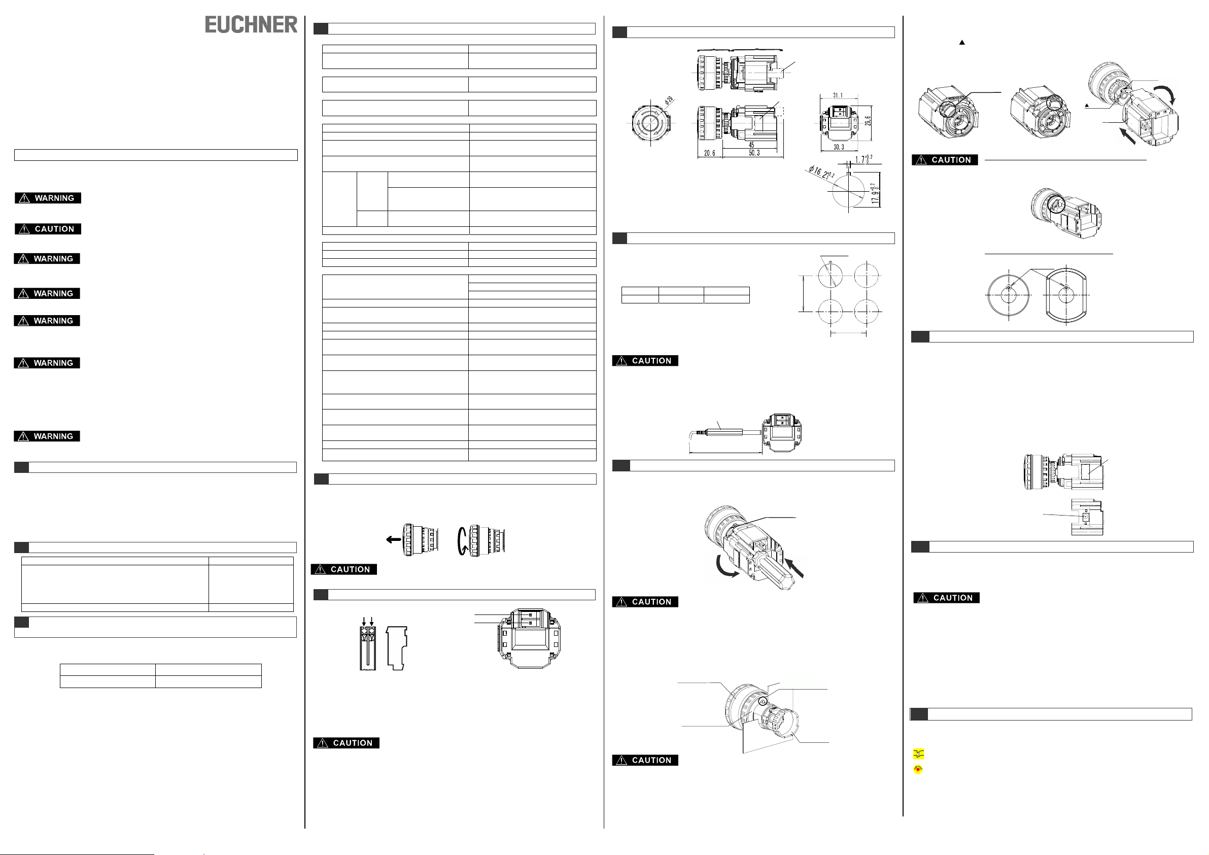
Dimensions
7
Operator uni
AS-Interface communication unit
AS-Interface communication c onnector
Addressing port
Mounting Hole Layout
8
Operator X axis Yaxis
Ø29 Min 40mm Min 40mm
·The values shown above are the minimum dimensions for
mounting with other Ø16mm pushbuttons. For other control
units of different sizes and styles, determine the values
according to the dimensions, operation, and wiring
convenience.
2
,
Installation
9
-Removing AS-Interface communication unit
First unlock the operator button. While pushing up the white bayonet ring with force, using a small
screwdriver (width: 2.5 to 3mm) if necessary, turn the AS-Interface communication unit
counterclockwise and pull out.
-Panel Mounting
Remove the locking ring from the operator and check that the rubber gasket is in place. Insert the
operator from panel front into the panel hole. Face the side with the anti-rotation protrusion on the
operator upward, and tighten the locking ring.
To set an address while mounting this product on the panel, more than
60mm space is necessary on the left side in terms of the AS-Interface
communication unit. Note that adequate space cannot be allocated by
the distance specified with minimum mounting pitch. If adequate space
cannot be allocated, set the address before installing the product on the
panel or set the address after removing the AS-Interface communication
unit from the operation section.
Programming cable
60.0
(2) Turn counterclockwise
Notes for removing an AS-Interface communication unit
(1) Do not exert excessive force when using a screwdriver, otherwise
the bayonet ring may be damaged.
(2) When removing the AS-Interface communication unit, avoid rough
handling of the unit. Rough handling may damage the switch.
Operator unit
Rubber Gasket
Notes for Panel Mounting
The panel thickness should be within the range from 0.8 to 3.7 mm. To
mount the ES-XA emergency stop switches onto a panel, tighten the
locking ring to a tightening torque of 0.88 N·m maximum using ring
wrench ES-MT-001. Do not use pliers. Do not exert excessive force,
otherwise the locking ring may be damaged.
Bayonet ring
Anti-rotation protr usion
Subject to technical modifications; no responsibility is accepted for the accuracy of this information. © EUCHNER GmbH + Co. KG 105027-04-02/10
Mounting hole dimension
16.2
(1) Push
Locking ring
+0.2_
0
-Installing the AS-Interface communication unit
First turn the bayonet ring to the unlocked position.
Align the small marking on the edge of the operator boss with the TOP marking on the
AS-Interface Communication unit onto the operator and turn the AS-Interface communication unit
clockwise until the bayonet ring clicks.
TOP marking
Bayonet Ring
Mark
TOP
Unlocked Locked
Notes for Installing the AS-Interface communication unit
Check that the AS-Interface communication unit is securely installed on
the operator. When the emergency stop switch is properly assembled,
the bayonet ring is in place as shown below.
Notes for using nameplate and switch guard
Remove the projection from the nameplate or switch guard using pliers.
X
Addressing
10
Turn off the power and then remove the lid of the address setting section. Connect the
programming cable to the address setting device and insert the device in the address setting
section. Then specify the address settings according to the setting procedures. After specifying
settings, be sure to replace the lid of the address setting section. Specifying address settings on
an AS-Interface slave is also possible using an AS-Interface master. Refer to the manual for the
AS-Interface master for details. Setting addresses 1 through 31 is allowed. The address specified
upon shipment is "0".
Refer to the address setting device instruction sheet for the operation of the address setting device.
-Connecting the programming cable for ES-XA address setting device
The lid of the address setting device on the side of the unit can be removed by prying it out. Take
care not to lose the lid, which comes off completely. By removing the lid of the address setting
section, you are able to see the terminals for connecting a programming cable. Connect the
programming cable to the terminals.
Projection
ddressing port for connecting
he programing cable is under the lid
Wiring
11
For cabling of this product, mount the connector sold separately to the compatible cable and
connect the main unit with the cable through the connector. A special tool is necessary to connect
the connector to the cable. When mounting a connector at the end of the cable, use a connector
for termination.
A maximum of 31 units can be connected to a network. Addresses must be assigned to avoid overlaps.
This product allows connecting safety slaves with safety equipment, and normal slaves without
safety equipment at the same time. Do not connect safety related signals to a normal slave.
The normal slaves for AS-Interface are divided into two types: A/B slaves with expanded
addresses and standard slaves without expanded addresses. If A/B slaves and standard slaves
are connected simultaneously, the maximum number of slaves connectable to a network may
exceed 31.
Setting Safety Monitor
12
When using this product in combination with a safety monitor, use a “2-channel forced” monitor
device with the “Emergency shutdown” icon.
2-channel forced
Emergency shutdown
EUCHNER GmbH + Co. KG Kohlhammerstraße 16 D-70771 Leinfelden-Echterdingen
Notes for setting up wiring
The network length is a maximum of 100 meters, including all wires.
However, the maximum possible length of the wires may actually be shorter
than 100 meters depending on the type of master and composition of slaves.
Consider the lengths of cables and wiring topology so that voltage drops in
transmission lines are no higher than 3V.
Use the applicable two-wire flat cables for wiring.
Tel. +49/711/75 97-0 Fax +49/711/75 33 16 www.euchner.de info@euchner.de
(1) Press
Lid of addressing port
(2) Turn
 Loading...