

Page 1
Time-Delayed S afety Re lay ESM-TE3 ..
User Information
Correct Use
Features
Function
The ESM-TE3.. is an expansion module that can be operated with
any basic device from the EUCHNER ESM series, e.g. ESM-BA2.. or
ESM-BA3.., in order to permit delayed switch-off of machine
parts. This could be the case if it is safer to return a tool to its
initial position first instead of stopping operation immediately,
for example. The ESM-TE3.. was developed as a component for a
modular system.
Any combination of ESM-TE3 units and non-time-delayed ESMES3.. expansion blocks can be interconnected with just a few
lines, permitting realization of an overall system with different
times and the specific number of safety contacts required.
•
3 safe, redundant, time-delayed relay outputs
1 auxiliary contact (fault monitoring)
•
Activation via basic device from the EUCHNER ESM
series
•
Continuously adjustable delay, 1 to 30s or fixed time
delay (ESM-TE3..-05S)
The time-delayed emergency stop safety switching device
ESM-TE3.. in combination with a basic device from the
EUCHNER ESM series is designed for safe isolation of
safety circuits according to EN 60204-1 and can be used
up to safety category 3, PL d according to EN ISO 13849-1.
The ESM-TE3.. provides a control voltage of DC 24V at
terminal S11. In order for the ESM-TE3.. to switch together
with the connected basic device, the control voltage at S11
is connected to terminals S15 and S16 of the ESM-TE3..
via one of the safety contacts of the basic device (see
Wiring section on page 2).
The safety contacts of the basic device close when the
basic device is activated, and the DC 24V control voltage at
terminal S11 is then connected with terminals S15 and S16
of the ESM-TE3... The safety contacts of the ESM-TE3..
switch immediately.
The basic device disconnects the control voltage when the
safety switch is operated, and the safety contacts of the
ESM-TE3.. open after the time set on the ESM-TE3..
elapses (the power supply must be present during the time
sequence).
If a fault occurs in the ESM-TE3.., this is detected by the
(not for plug-in termnals
and fixed-time types)
•
Modular, freely configurable safety system
•
Corresponds to STOP category 1
•
Fault monitoring by basic device
•
Indication of the switching state via LED
•
Up to PL d, category 3, SILCL 2
basic device via terminals S25 and S26.
Independent operation without basic device is not possible.
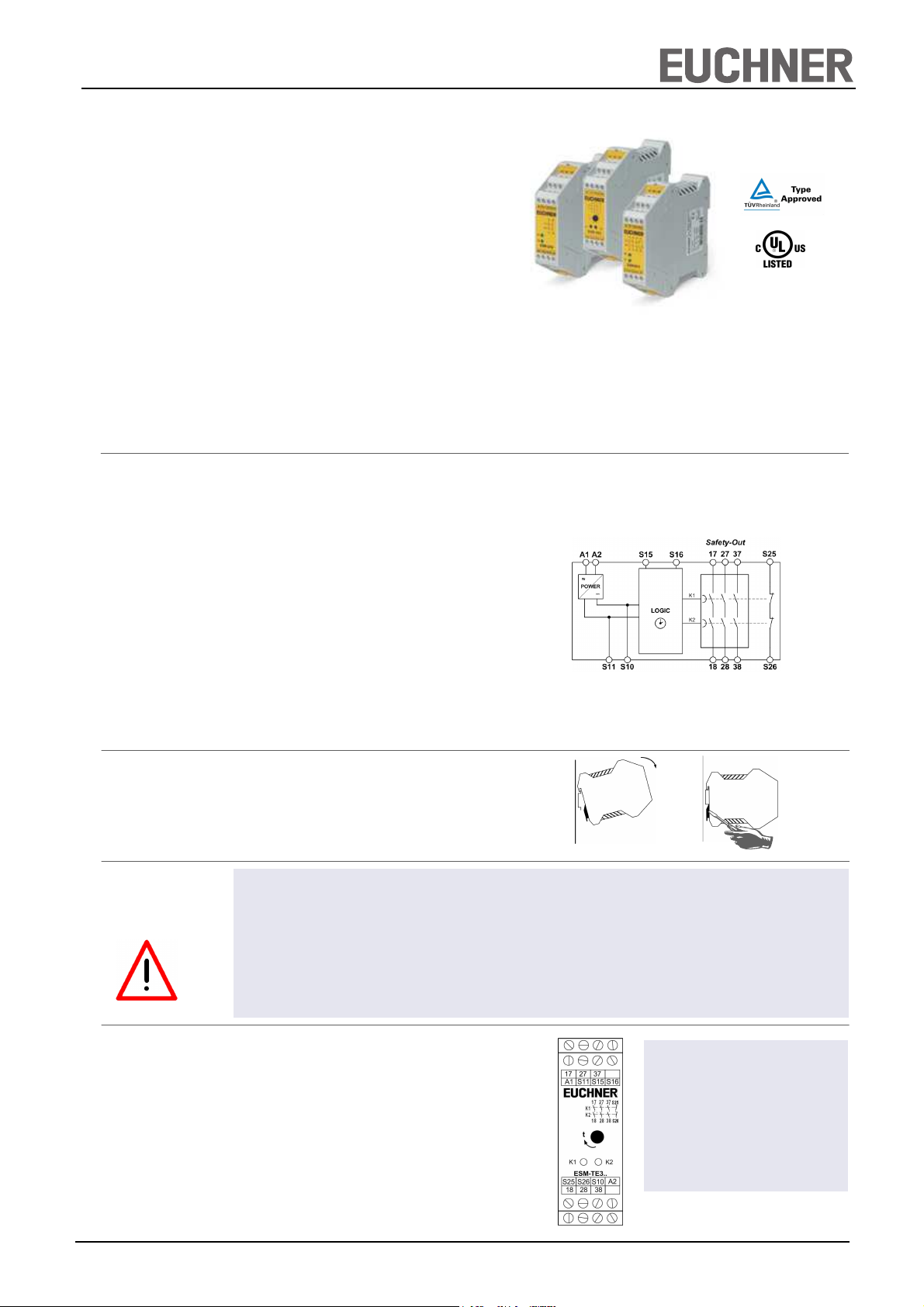
Fig. 1 Block diagram ESM-TE3..
Installation
Safety
Precautions
Electrical
Connection
As per EN 60204-1, the device is intended for installation in
control cabinets with a minimum degree of protection of
IP54. It is mounted on a 35-mm DIN rail according to DIN
EN 60715 TH35.
•
Installation and commissioning of the device must be
performed only by authorized personnel.
•
Observe the country-specific regulations when installing
the device.
•
The electrical connection of the device is only allowed to
be made with the device isolated.
•
The wiring of the device must comply with the instructions in this user information, otherwise there is a risk
that the safety function will be lost.
•
When the 24 V version is used, a safety transformer
according to EN 61558-2-6 or a power supply unit with
electrical isolation from the mains must be connected.
•
External fusing of the safety contacts (4 A slow-blow or 6
A quick-action or 10 A gG) must be provided.
•
A maximum length of the control lines of 1000 meters
with a line cross section of 0.75 mm2 must not be exceeded.
•
The line cross section must not exceed 2.5 mm2.
•
If the device does not function after commissioning, it
must be returned to the manufacturer unopened. Opening the device will void the warranty.
Fig. 2 Installation / removal
•
It is not allowed to open the device, tamper with the device or bypass the safety devices.
•
All relevant safety regulations and standards are to be
observed.
•
The overall concept of the control system in which the
device is incorporated must be validated by the user.
•
Failure to observe the safety regulations can result in
death, serious injury and serious damage.
A1: Power supply
A2 : Power supply
S11: DC 24V control voltage
S10: Control line
S15: Control line
S16: Control line
S25: Fault monitoring
S26: Fault monitoring
17-18: Time-delayed safety contact 1
27-28: Time-delayed safety contact 2
37-38: Time-delayed safety contact 3
Fig. 3 Connections
EUCHNER GmbH + Co. KG Kohlhammerstraße 16 D-70771 Leinfelden-Echterdingen Tel. +49/711/75 97-0 Fax +49/711/75 33 16 www.euchner.de info@euchner.de
1
Page 2
Time-Delayed S afety Re lay ESM-TE3 ..
User Information
Applications
Wiring
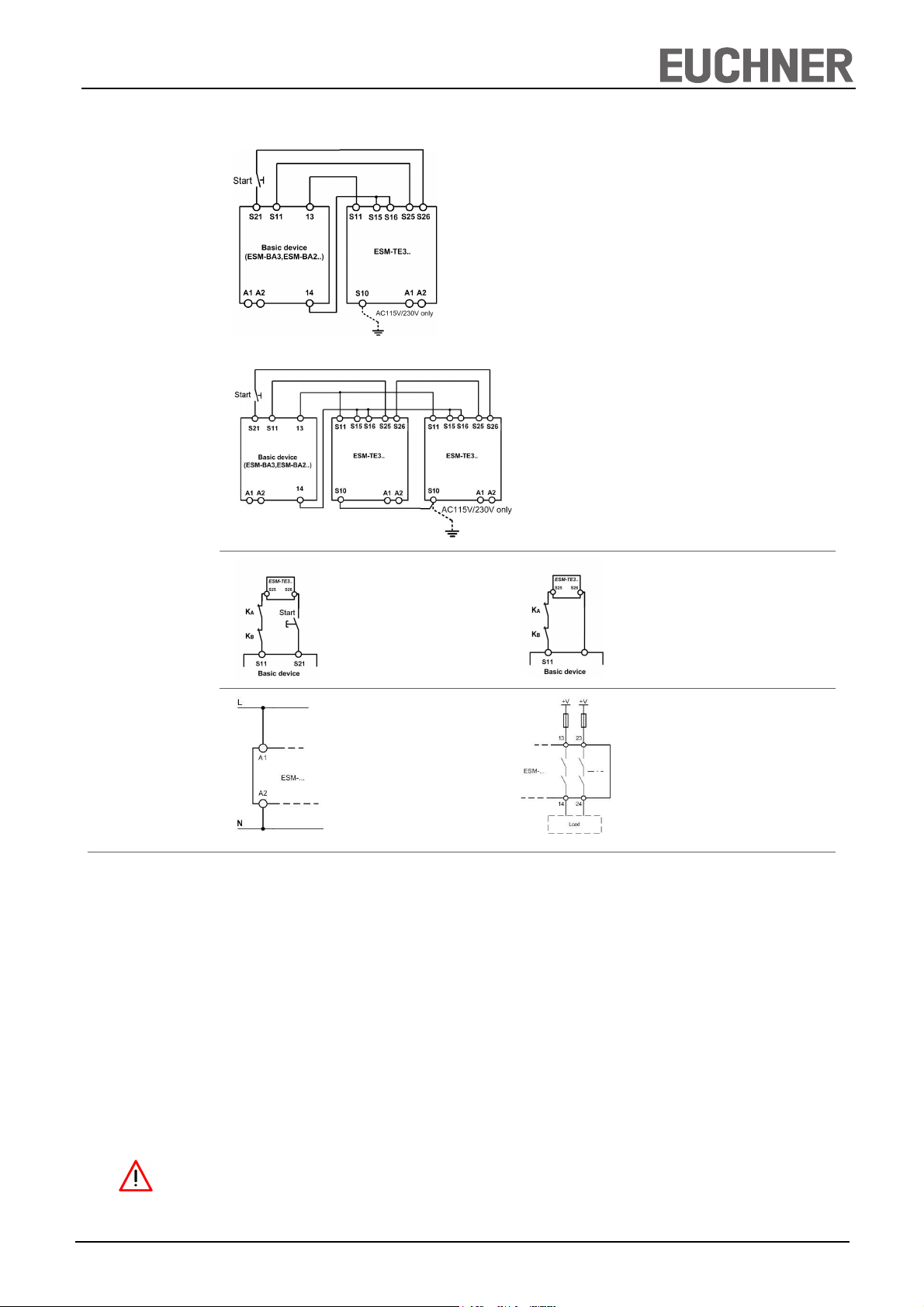
Depending on the application, the device must be wired with a EUCHNER basic device as shown in Fig. 1 to Fig. 2.
Fig. 1: Connection of ESM-TE3.. to basic device
Wiring of the ESM-TE3.. via only 4 lines:
A safety contact of the EUCHNER basic device (e.g. 13-14)
activates the relays of the ESM-TE3.. (S11 and S15/S16).
Two lines on S25 and S26 are required for feedback/fault
monitoring. A fault in the ESM-TE3.. thereby prevents the
entire safety chain from restarting. Earth faults in the control
lines are detected in addition to internal faults.
Fig. 2: Connection of several ESM-TE3.. units to
basic device
If further ESM-TE3.. units are to be integrated into the system,
terminals S11 must be connected in parallel on all ESM-TE3..
units. This also applies to terminals S10 and terminals S15/S16.
Notice:
In order to activate earth fault monitoring, S10 must be connected to PE (protective earth) on the AC115/230V devices.
With AC/DC 24 V, connect PE only to the power supply unit
according to EN60204-1.
Feedback Loop
Power supply
and
Safety contacts
Commissioning
Procedure
Fig. 3: Feedback Loop
Contactors connected to the ESM-TE3..
or the basic devices are monitored via
the feedback loop of the basic device.
KA and KB are the positively driven
contacts of the connected contactor or
expansion module.
Fig. 5:
Power supply A1 and A2.
(Power supply according to techn.
data )
S12
Fig. 4: Feedback Loop with Auto-Start
Contactors connected to the ESM-TE3.. or the
basic devices are monitored via the feedback
loop of the basic device. KA and KB are the
positively driven contacts of the connected
contactor or expansion module.
Fig. 6:
Connecting load to safety contacts.
(Figure shows example.
Voltage „+V“ according to techn.
data)
Hinweis: Während der Inbetriebnahme sind die unter „Elektrischer Anschluss“ aufgeführten Punkte zu berücksichtigen.
1. Wiring ESM-TE3..:
Wire the ESM-TE3.. with the EUCHNER basic device
according to your application (see Fig. 1 to Fig. 2).
2. Wiring basic device:
Wire the basic device according to the required Performance Level determined (see user information for the basic
device).
3. Wiring feedback loop:
Wire the feedback loop as shown in Fig. 3 and Fig. 4.
4. Wiring power supply:
Connect the power supply to terminals A1 and A2 (Fig. 5).
Warning: Wiring only in de-energized state.
5. Setting delay time:
Set the desired time delay on the rotary knob and seal the
knob with the supplied sticker.
(Not for ESM-TE3..-05S because of 0.5 seconds fixed
delay time).
Warning:
Scale division lines should be regarding only as a setting
aid. Always make sure to measure the delay time.
6. Starting the device:
Switch the operating voltage on.
Warning:
If the “Automatic start” starting behavior is set on the basic
device, the safety contacts will close immediately.
If the “Monitored manual start” starting behavior is set, close
the start button on the basic device to close the safety
contacts.
The LEDs K1 and K2 on the basic device and on the ESMTE3.. are lit when the safety contacts are closed.
7. Triggering safety function:
Open the emergency stop circuit by actuating the connected safety switch. The safety contacts of the basic device open immediately; the safety contacts of the ESMTE3.. open after expiration of the time set on the rotary
knob.
Warning: Measure the delay time.
8. Reactivation:
Close the emergency stop circuit. If “Automatic start” is
selected on the basic device, the safety contacts will close
immediately.
If the “Monitored manual start” starting behavior is set, close
the start button on the basic device to close the safety
contacts of the basic device and the ESM-TE3...
EUCHNER GmbH + Co. KG Kohlhammerstraße 16 D-70771 Leinfelden-Echterdingen Tel. +49/711/75 97-0 Fax +49/711/75 33 16 www.euchner.de info@euchner.de
2
Page 3

Time-Delayed S afety Re lay ESM-TE3 ..
User Information
Maintenance
What to Do in
Case of a Fault?
Safety
Characteristics
According to
EN ISO 13849-1
Once per month, the device must be checked for proper
function and for signs of tampering and bypassing of the
safety function (to do this, check the wiring of the device and
activate the emergency stop function. Check the delay time).
Device does not switch on:
•
Check the wiring of the ESM-TE3..and the basic device
by comparing it with the wiring diagrams (also see user
information for the basic device).
•
Check the safety switch used on the basic device for
correct function and adjustment.
•
Check whether the emergency stop circuit of the basic
device is closed.
•
Check whether the start button on the basic device (with
manual start) is closed.
•
Check the operating voltage at A1 and A2 on the basic
device and on the ESM-TE3...
•
Is the feedback loop closed?
The device is certified according to EN ISO 13849-1 up to a
Performance Level of PL e.
Safety characteristics according to EN ISO 13849-1 for all variants of ESM-TE3
Load (DC-13; 24V) <= 0,1A <= 1A <= 2A
T10d [years] 20 20 20
The device is otherwise maintenance free, provided that it
was installed properly.
Device cannot be switched on again after an emergency
stop:
•
Check whether the emergency stop circuit was closed
again.
•
Was the start button opened before closing of the emergency stop circuit (with manual start)?
•
Is the feedback loop closed?
•
Is the power supply present during the time sequence?
If the fault still exists, perform the steps listed under
“Commissioning Procedure”.
If these steps do not remedy the fault either, return the
device to the manufacturer for examination.
Opening the device is impermissible and will void the
warranty.
Note:
Additional data can be requested from the manufacturer for
applications that deviate from these conditions.
Techn. Data
Category: 3 3 3
PL D d d
PFHd [1/h]: 1,03E-07 1,03E-07 1,03E-07
nop [cycle / year] <= 400.000 <= 73.000 <= 17.000
Operating voltage ESM-TE301 ESM-TE302 ESM-TE303
AC/DC 24 V AC 115V AC 230V
Rated supply frequency 50-60 Hz
Permissible deviation + / - 10%
Power consumption DC 24V AC 230V
approx. 1.5 W approx. 4 VA
Delay time
ESM-TE3.. 1 to 30 s, continuously adjustable
ESM-TE3..-05S 0.5 s fixed
Control voltage at S11 DC 24 V
Control current S11...S14 max. 40mA
Safety contacts 3 NO contacts
Signaling contacts 1 NC contact; monitoring contact for basic device
Max. switching voltage AC 250 V
Safety contact breaking capacity AC: 250 V, 1500 VA, 6 A for ohmic load,
250 V, 4 A for AC-15
DC: 24 V, 30 W, 1.25 A for ohmic load;
24 V, 30 W, 2 A for DC-13
Max. total current through all 3 contacts: 10.5 A
Minimum contact load 24 V, 20mA
Contact fuses 4 A slow-blow or 6 A quick-action or 10 A gG
Line cross section 0.14 - 2.5 mm2
Max. length of control line 1000 m with 0.75 mm2
Contact material AgNi
Contact service life mech. approx. 1 x 10⁷, electr. 1 x 10⁵ operating cycles
Test voltage 2.5 kV (control voltage/contacts)
Rated impulse withstand voltage, leakage path/air gap 4 kV (DIN VDE 0110-1)
Rated insulation voltage 250 V
Degree of protection IP20
Temperature range DC 24V: -15°C to +60°C
AC 230V/115V/24V: -15°C to +40°C
Degree of contamination 2 (DIN VDE 0110-1)
Overvoltage category 3 (DIN VDE 0110-1)
Weight approx. 230g
Mounting DIN rail according to EN 60715TH35
EUCHNER GmbH + Co. KG Kohlhammerstraße 16 D-70771 Leinfelden-Echterdingen Tel. +49/711/75 97-0 Fax +49/711/75 33 16 www.euchner.de info@euchner.de
3
Page 4

Time-Delayed S afety Re lay ESM-TE3 ..
User Information
Dimension
Drawing
99
22,5
114
EUCHNER GmbH + Co. KG Kohlhammerstraße 16 D-70771 Leinfelden-Echterdingen Tel. +49/711/75 97-0 Fax +49/711/75 33 16 www.euchner.de info@euchner.de
Subject to technical modifications, no responsibility is accepted for the accuracy of this information. © EUCHNER GmbH + Co. KG 090075-06-11/13 (Translation of the Original Operating Instructions)
4
 Loading...