

Page 1
Safety Relay, Series ESM-BT4..
User Information
Correct Use ESM-BT4.. is an emergency stop safety relay combination that
combines non-time-delayed and time-delayed contacts in a very
compact housing. This permits dangerous components of a
system to be switched off quickly and safely in an emergency
situation. At the same time, other circuits can continue to be
supplied with voltage for up to 30 seconds to allow a tool to be
moved to its idle position or to brake following parts, for example.
•
Features
Function
4 positively driven safety relays contacts. Possible variants:
- 3 non-time-delayed and 1 time-delayed contact
- 2 non-time-delayed and 2 time-delayed contact
- 1 non-time-delayed and 3 time-delayed contact
•
Continuously adjustable time delay (1 bis 30s) or fixed
time delay (ESM-BT4..-20S (2s); ESM-BT4..-50S (5s))
•
Connection of:
- emergency stop buttons
- safety switches
- non-contacts safety switches
- OSSD-Outputs
•
1- or 2-channel activation possible
The moving parts of a machine or system can be quickly
and safely stopped in case of danger with the non-timedelayed contacts of the ESM-BT4...Safety contacts with
time-delay switch-off are also integrated into the
ESM-BT4... They are used whenever it is safer to keep
supplying voltage to parts of a machine after the emergency stop switch is operated.
It is ensured that a single fault or malfunction does not lead
to a loss of the safety function and that every fault is detected by cyclical self-monitoring no later than when the
(not for plug-in terminals)
(Fixed time-delay pending)
•
Feedback loop for monitoring downstream contactors or
expansion modules
•
Cyclical monitoring of the output contacts
•
Indication of the switching state via LED
•
2 start behaviors possible:
- monitored manual start
- automatic start
•
Short circuit and earth fault monitoring
•
Up to PL e, SILCL 3, category 4
system is switched off and switched on again.
The time-delay contacts are activated at the same time as
the non-time-delay contacts; however, when the emergency stop button is pressed, the contacts are only deactivated after the time set on the potentiometer (1 … 30s) or
after a fixed time delay (ESM-BT4..-20S; ESM-BT4..-50S)
Installation
Safety
Precautions
Electrical
Connection
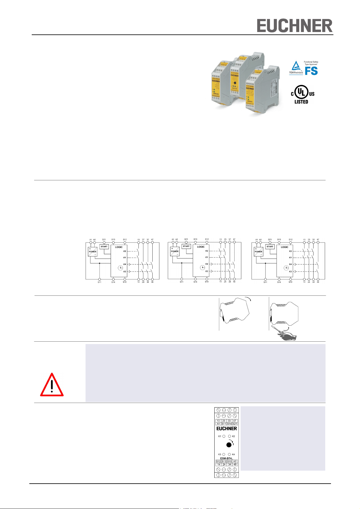
Fig. 1 Block diagram: ESM-BT401 (1nd/3d); ESM-BT411 (2nd/2d); ESM-BT421(3nd/1d)
As per DIN EN 60204-1, the device is intended for installation in control cabinets with a minimum degree of protection
of IP54. It is mounted on a 35-mm DIN rail according to
DIN EN 60715 TH35.
Fig. 2 Installation/removal
•
Installation and commissioning of the device must be
performed only by authorized personnel.
•
Observe the country-specific regulations when installing
the device.
•
The electrical connection of the device is only allowed to
be made with the device isolated.
•
The wiring of the device must comply with the instructions in this user information, otherwise there is a risk that
the safety function will be lost.
•
A safety transformer according to EN 61558-2-6 or a
power supply unit with electrical isolation from the mains
must be connected.
•
External fusing of the safety contacts (6A slow-blow or
8A quick-action or 10AgG) must be provided.
•
A maximum length of the control lines of 1000 meters
with a line cross section of 0.75 mm
ded.
•
The line cross section must not exceed 2.5 mm2.
•
If the device does not function after commissioning, it
must be returned to the manufacturer unopened. Opening the device will void the warranty.
2
must not be excee-
•
It is not allowed to open the device, tamper with the device or bypass the safety devices.
•
All relevant safety regulations and standards are to be
observed.
•
The overall concept of the control system in which the
device is incorporated must be validated by the user.
•
Failure to observe the safety regulations can result in
death, serious injury and serious damage.
A1: Power supply
A2 : Power supply
S11: DC 24V control voltage
S10: Control line
S12: Control line
S13: Control line
S14: Control line
S21: Start, Control line
13-14: Safety contact 1 (nd)
23-24/27-28: Safety contact 2 (d / nd)
33-34/37-38: Safety contact 3 (d / nd)
47-48: Safety contact 4 (d)
Fig. 3 Connections
nd = non-time delayed; d = time-delayed
EUCHNER GmbH + Co. KG Kohlhammerstraße 16 D-70771 Leinfelden-Echterdingen Tel. +49/711/75 97-0 Fax +49/711/75 33 16 www.euchner.de info@euchner.de
1
Page 2
Safety Relay, Series ESM-BT4..
User Information
Applications
Emergency Stop
Circuit
Starting Behavior
Feedback Loop
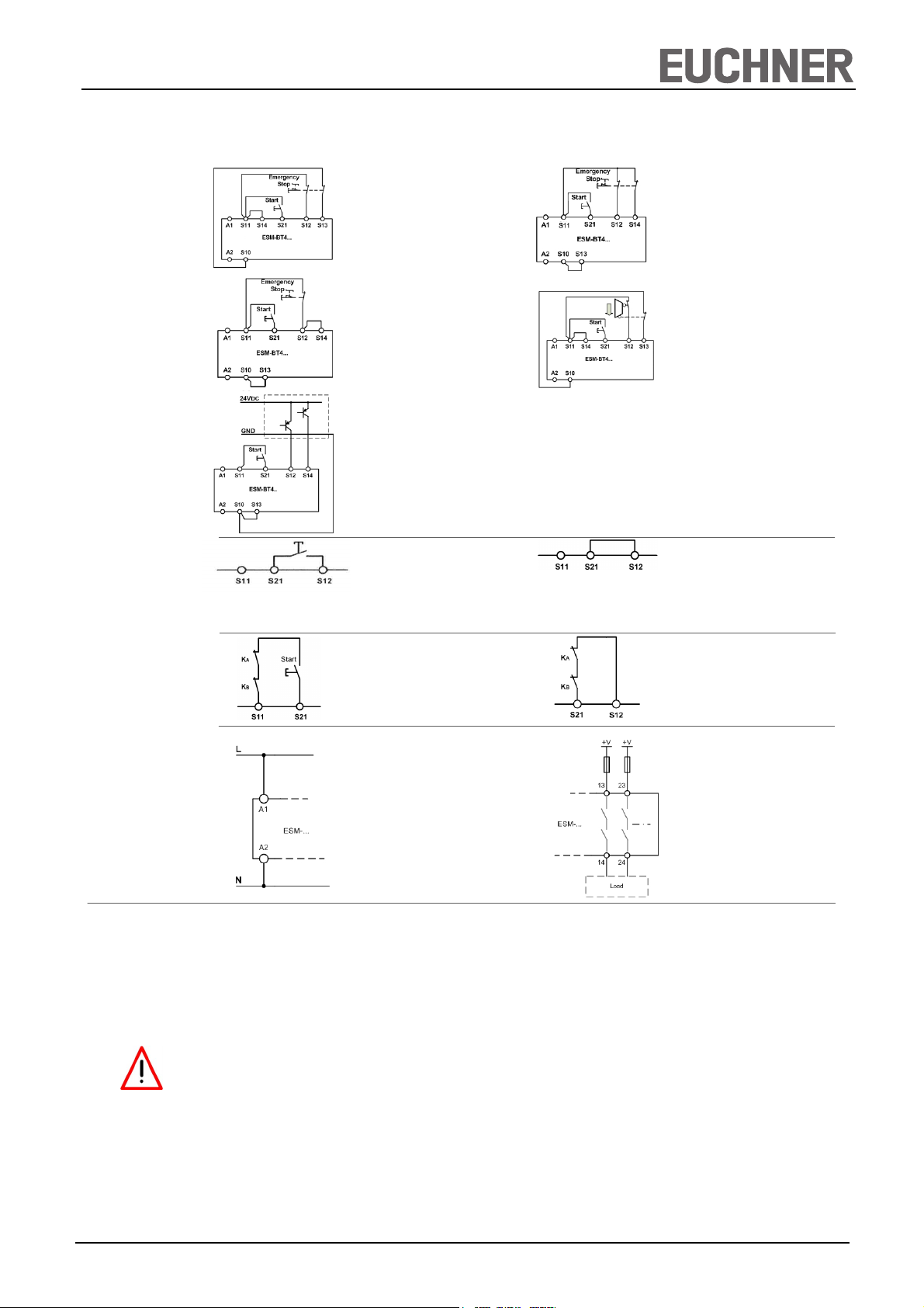
Depending on the application or the result of the risk assessment according to EN ISO 13849-1, the device must be wired as
shown in Fig. 1 to Fig. 11. Non-time delayed contacts can be used up to category 4, PL e, time-delayed safety contacts up to
category 3, PL e.
Fig. 1:
Two-channel emergency stop circuit with
short circuit and earth
fault monitoring.
(category 4, up to PL e)
Fig. 3:
Single-channel emergency stop circuit with
earth fault monitoring.
(category 1, up to PL c)
Fig. 5:
Two-channel emergency stop
with pnp-outputs/OSSD-outputs
with short circuit monitoring.
(category 4, up to PL e)
Fig. 6:
Manual start.
Fig. 8:
Feedback loop for monitored manual
start:
The feedback loop monitors contactors
or the expansion modules .
Warning:
In order to activate earth fault monitoring, the PE must be
connected only to the power supply unit in accordance with
EN60204-1.
Warning:
Safety contacts switch
when the power supply is
connected.
Fig. 2:
Two-channel emergency stop circuit with earth
fault monitoring.
(category 3, up to PL d)
Fig. 4:
Two-channel sliding
guard monitoring with
short circuit and earth
fault monitoring.
(category 4, up to PL e)
Fig. 7:
Automatic start (e.g. for application with
a safety door).
Max perm. delay during closing of the
safety switches on S12 and S13:
S12 before S13: 300ms;
S13 before S12: any
Fig. 9:
Feedback loop for automatic start:
The feedback loop monitors contac-
tors or the expansion modules .
Power supply
and
Safety contacts
Commissioning
Procedure
Fig. 10:
Power supply A1 and A2.
(Power supply according to techn.
data )
Note: The items listed under “Electrical connection” must be observed during commissioning.
1. Wiring emergency stop circuit:
Wire the emergency stop circuit according to the required
Performance Level determined (see Fig. 1 to Fig 5).
2. Wiring start circuit:
Wire the start circuit according to Fig. 6 or Fig. 7 to set the
starting behavior.
Warning:
If “Automatic start” is set, bear in mind that the safety contacts will switch immediately after the power supply is
connected. If “Monitored manual start” is set, the start
button must be opened after wiring.
3. Wiring feedback loop:
If your application provides for external contactors or expansion modules, connect them to the device according to
Fig. 8 or Fig. 9.
4. Wiring power supply:
Connect the power supply to terminals A1 and A2 (Fig. 10).
Warning: Wiring only in de-energized state.
5. Set time delay:
Set the desired time delay on the rotary knob (not for fixed
delay time)
Warning:
Scale divisions should be regarding only as a setting aid.
Always make shure to measure the delay time.
6. Starting the device:
Switch on the operating voltage.
Warning:
If the “Automatic start” starting behavior is set, the safety
contacts will close immediately.
If the “Monitored manual start” starting behavior is set, close
the start button to close the safety contacts.
LEDs K1, K2, K3 and K4 are lit.
7. Triggering safety function:
Open the emergency stop circuit by actuating the connected safety switch. The safety contacts open immediately.
Warning: Measure the delay-time.
8. Reactivation:
Close the emergency stop circuit. If “Automatic start” is
selected, the safety contacts will close immediately.
If the “Monitored manual start” starting behavior is set, close
the start button to close the safety contacts.
Fig. 11:
Connecting load to safety contacts.
(Figure shows example.
Voltage „+V“ according to techn.
data)
EUCHNER GmbH + Co. KG Kohlhammerstraße 16 D-70771 Leinfelden-Echterdingen Tel. +49/711/75 97-0 Fax +49/711/75 33 16 www.euchner.de info@euchner.de
2
Page 3

Safety Relay, Series ESM-BT4..
User Information
Maintenance
What to Do in
Case of a Fault?
Safety
Characteristics
According to
EN ISO 13849-1
The device must be checked once per month for proper
function and for signs of tampering and bypassing of the
safety function (to do this, check the wiring of the device
and activate the emergency stop function. Check the delay
time).
Device does not switch on:
•
Check the wiring by comparing it to the wiring diagrams.
•
Check the safety switch used for correct function and
adjustment.
•
Check whether the emergency stop circuit is closed.
•
Check whether the start button (with manual start) is
closed.
•
Check the operating voltage at A1 and A2.
•
Is the feedback loop closed?
The device is certified according to EN ISO 13849-1 up to a
Performance Level of PL e.
Safety characteristics according to EN ISO 13849-1 for all variants of ESM-BT4
Load (DC-13; 24V) <= 0,1A <= 1A <= 2A
T10d [years] 20 20 20
Category:
Time-delay
Non-time-delay
PL e e e
PFHd [1/h]:
Time-delay
Non-time-delay
nop [cycle / year] <= 500.000 <= 350.000 <= 100.000
3
4
8,84E-08
4,22E-08
The device is otherwise maintenance free, provided that it
was installed properly.
Device cannot be switched on again after an emergency
stop:
•
Check whether the emergency stop circuit was closed
again.
•
Was the start button opened before closing of the emergency stop circuit (with manual start)?
•
Is the feedback loop closed?
If the fault still exists, perform the steps listed under
“Commissioning Procedure”.
If these steps do not remedy the fault either, return the
device to the manufacturer for examination.
Opening the device is impermissible and will void the
warranty.
Note:
Additional data can be requested from the manufacturer for
applications that deviate from these conditions.
3
4
8,84E-08
4,22E-08
3
4
8,84E-08
4,22E-08
Techn. Data
Operating voltage AC/DC 24V
Rated supply frequency 50 - 60 Hz
Permissible deviation +/- 10%
Power consumption DC 24V AC 24V
approx. 4.7W approx. 5.3VA
Control voltage at S 11 DC 24V
Control current approx. 190mA
Response delay after actuation of the buttons < 20ms
Safety contacts 4 NO contacts (3n/1d, 2n/2d, 1n/3d)
Max. switching voltage AC 250V
Safety contact breaking capacity AC: 250V, 2000VA, 8A for omic load
250V, 3A for AC-15
DC: 50V, 8A for omic load
24V, 3A for DC-13
Max. cumulative current on the safety contacts 15A *
Time delay
ESM-BT4.. 1 ... 30s, continuously adjustable
ESM-BT4..-20S 2s fixed
ESM-BT4..-50S 5s fixed
Minimum contact load 24V, 20mA
Contact fuses T6A, F8A, 10A gG
Line cross section 0.14 - 2.5mm
Max. length of control line 1000m at 0.75mm2
Contact material AgSnO2
Contact service life mech. approx. 1 x10⁷, electr. 1 x 10⁵ operating cycles
Test voltage 2.5kV (control voltage/contacts)
Rated impulse withstand voltage, leakage path/air gap; 4kV (DIN VDE 0110-1)
Rated insulation voltage 250V
Degree of protection IP20
Degree of contamination 2 (DIN VDE 0110-1)
Overvoltage category 3 (DIN VDE 0110-1)
Temperature range -15°C ... +40°C
Weight approx. 250g
Mounting DIN rail according to EN 60715TH35
2
*) If several ESM-BT4.. devices are closely spaced under load, the max. total current at the ambient temperature of T=20°C: 9A; at T=30°C: 3A; at T=40°C =1A.
If these currents are exceeded, a spacing of 5 mm between the devices must be observed.
EUCHNER GmbH + Co. KG Kohlhammerstraße 16 D-70771 Leinfelden-Echterdingen Tel. +49/711/75 97-0 Fax +49/711/75 33 16 www.euchner.de info@euchner.de
3
Page 4

Safety Relay, Series ESM-BT4..
User Information
Dimension
Drawing
99
22,5
114
EUCHNER GmbH + Co. KG Kohlhammerstraße 16 D-70771 Leinfelden-Echterdingen Tel. +49/711/75 97-0 Fax +49/711/75 33 16 www.euchner.de info@euchner.de
Subject to technical modifications, no responsibility is accepted for the accuracy of this information. © EUCHNER GmbH + Co. KG 109074-04-09/11 (Translation of the Original Operating Instructions)
4
 Loading...