

Page 1
2-Hand Safety Relay, Series ESM-2H2..
User Information
Correct Use
Features
Function
The ESM-2H2.. 2-hand safety relay is an extremely
compact, universal safety two-hand control unit. It
complies with EN574, Typ III C, and is intended for use
in safety circuits that are designed in accordance with
EN 60204-1, e.g. on presses, punches and bending
tools. Due to the internal error monitoring, the 2-hand
safety relay can be used, despite very compact dimensions, for all applications up to the highest safety category 4 and PL e according to EN ISO 13849-1, SILCL 3
according to EN 62061 or Typ III C according to EN 574.
•
2 safe, redundant relay outputs
•
Cyclical monitoring of the output contacts
•
Feedback loop for monitoring downstream contactors or
expansion modules
•
Short circuit and earth fault monitoring
•
Extrem compact housing
The EUCHNER 2-hand safety relay ESM-2H2.. is suitable
for setting up and monitoring two-hand circuits and is used
to protect the operators. Dangerous work steps can only be
triggered when both two-hand buttons connected are operated simultaneously, i.e. within 0.5s.
It is to be ensured a single fault or a malfunction does not
result in the loss of the safety function and every fault is
detected by the cyclic self-monitoring at the latest prior to
the next actuation.
When the operating voltage is applied to A1-A2 and the
feedback loop X1-X2 is closed, the ESM-2H2.. is ready for
use. To be able to initiate a switching operation, the output
relays must be de-energized. The output relays only switch
to the energized position when the two-hand buttons T1
and T2 are operated simultaneously, i.e. within 0.5s.
•
Up to PL e, SILCL 3, category 4
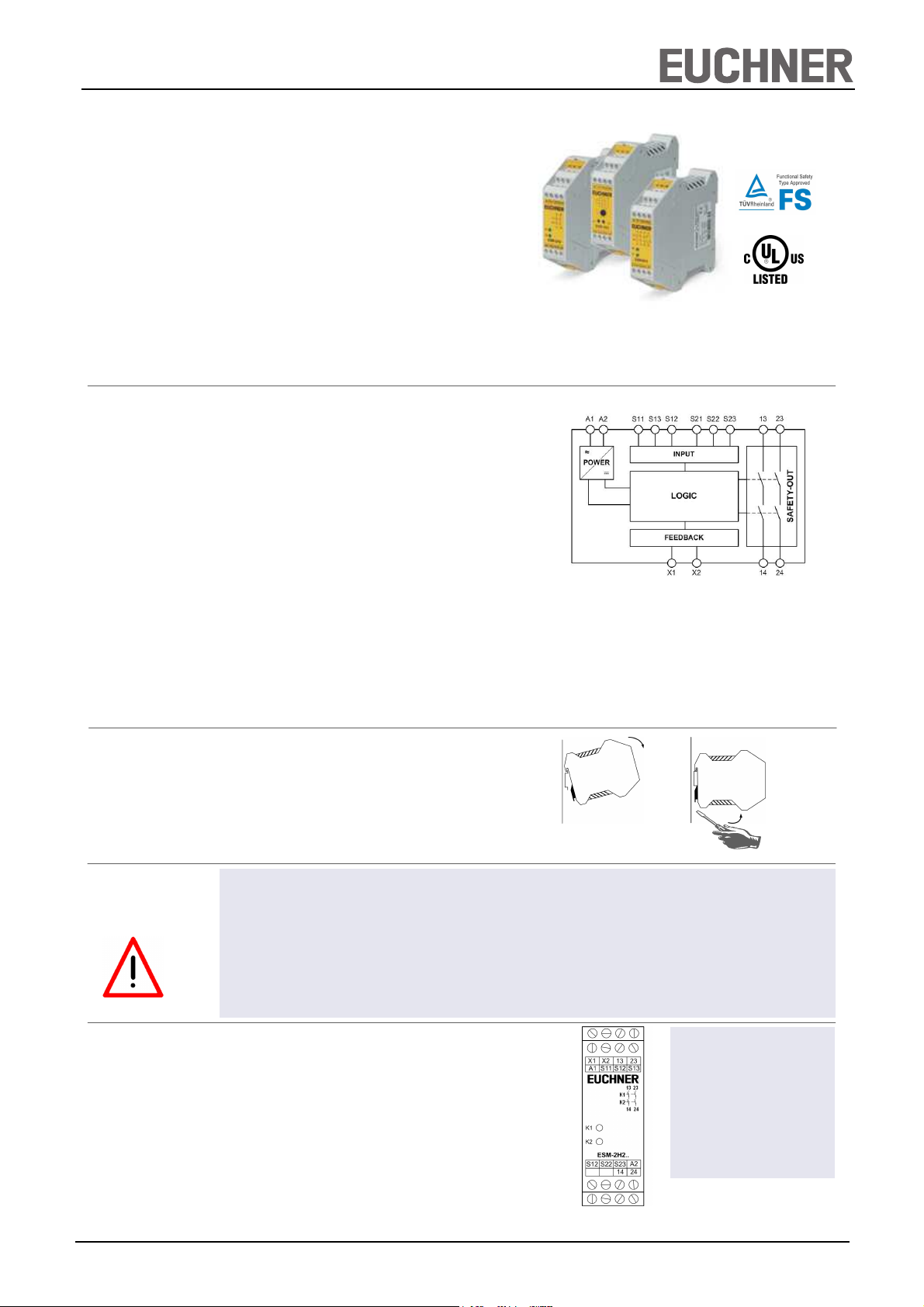
Fig. 1 Block diagram ESM-2H2..
(not dor plug-in terminals)
Installation
Safety Precautions
Electrical Connection
The output relays are not switched if:
•
only one two-hand button is actuated or the time between the actuation of the 2 two-hand buttons is greater than 0.5s,
•
the feedback loop is open (fault in the external contactor),
•
another error (short circuit, cable break, error in the switching device) has occurred.
When T1 and/or T2 are/is released, the output relays opens immediately. In order to trigger a new operation, both two-hand
buttons must first be released and the feedback loop must be closed.
As per DIN EN 60204-1, the device is intended for installation in control cabinets with a minimum degree of protection
of IP54. It is mounted on a 35-mm DIN rail according to
DIN EN 60715 TH35.
Fig. 2 Installation/removal
•
•
Installation an setup are only allowed to be undertaken
by trained personell.
•
The electrical connection is only allowed to be made with
the device and wiring isolated.
•
The wiring must comply with the instructions in this user
information, otherwise there is a risk that the safety
function will be lost.
•
As per EN 60204-1 the device is intended for installation
in control cabinets with a minimum degree of protection
of IP54.
•
When the 24V version is used, a safety transformer
according to EN 61558-2-6 or a power supply unit with
electrical isolation from the mains must be connected.
•
External fusing of the safety contacts (4A slow-blow or
6A quick-action or 10A gG) must be provided.
•
A maximum length of the control lines of 1000 meters
with a line cross section of 0.75 mm2 must not be exceeded.
•
The line cross section must not exceed 2.5 mm2.
•
If the device does not function after commissioning, it
must be returned to the manufacturer unopened. Opening the device will void the warranty.
It is not allowed to open the device, tamper with the device or bypass the safety devices.
•
All relevant sefety regulations and standards are to be
observed.
•
The overall concept for the control system in which the
device is integrated is to be validated.
•
Failure to observe the safety regulations can result in
death, serious injury and serious damage.
A1: Power supply
A2. Power supply
S11: Control line T1
S12: Control line T1
S13: Control line T1
S21: Control line T2
S22: Control line T2
S23: Control line T2
X1; X2: Feedback loop
13-14: Safety contact 1
23-24: Safety contact 2
Fig. 3 Connections
EUCHNER GmbH + Co. KG Kohlhammerstraße 16 D-70771 Leinfelden-Echterdingen Tel. +49/711/75 97-0 Fax +49/711/75 33 16 www.euchner.de info@euchner.de
1
Page 2
2-Hand Safety Relay, Series ESM-2H2..
User Information
Applications
Feedback loop
Installation
The arrangement of the two-hand buttons must be designed in accordance with the standard EN 574 such that accidental
actuation or simple bypassing of the safety function is excluded.
The ESM-2H2.. unit is provided for the connection of 2-hand push-buttons, with one normally open or one normally colsed
contact.
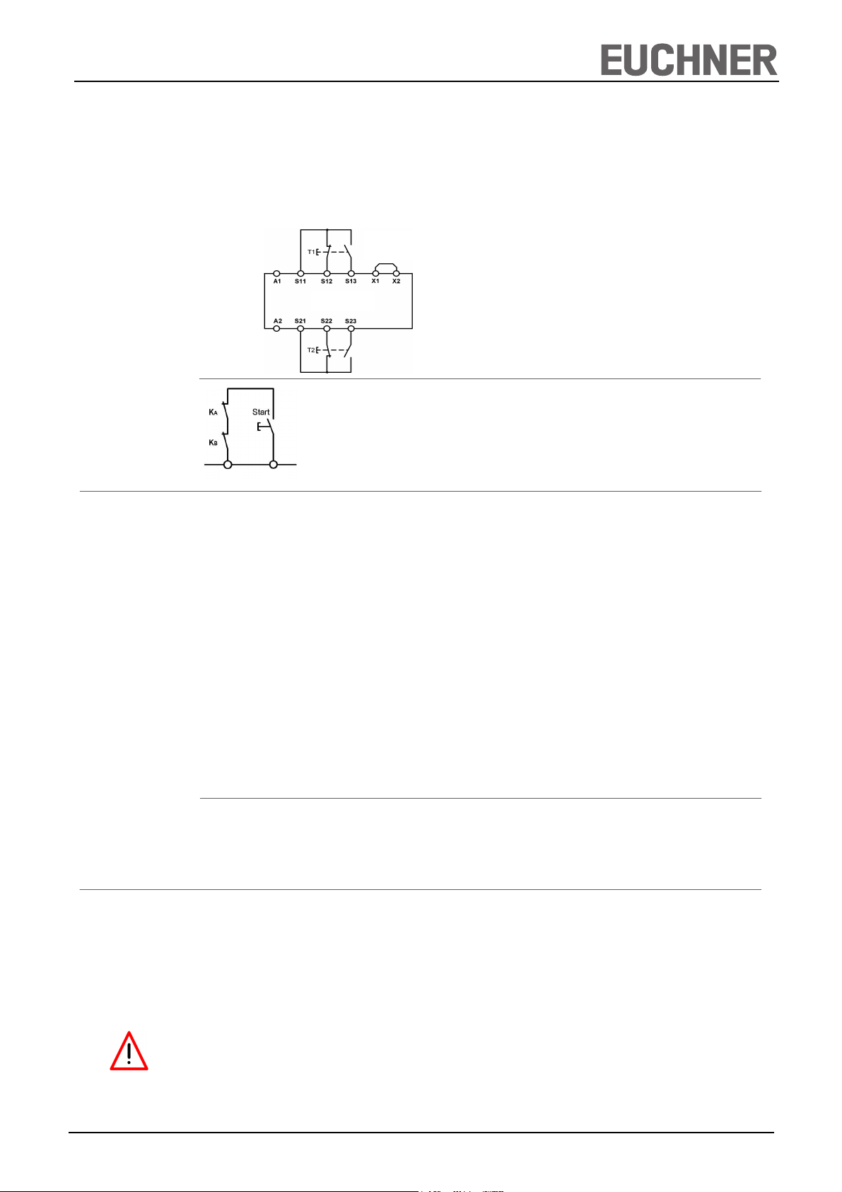
Figur 1 shows the wiring of the ESM-2H2.. with a 2-hand push-buttons:
Jumper X1-X2:
See description
ESM-2H2..
Fig. 1:
Wiring of the ESM-2H2.. with a 2-hand push
-buttons
Fig. 2: Feedback loop
Contactors connected to the ESM-2H2.. or the basic devices
are monitored via the feedback loop of the basic device. KA
and KB are the positively driven contacts of the connected
contactor or expansion module.
X1
Avoiding unintentional actuation or bypassing of the safety device
The arrangement of the two-hand buttons must be designed in accordance with the standard EN 574 such that accidental
actuation or simple bypassing of the safety function is excluded.
The operation of both buttons using one hand must be prevented by an adequate distance (at least 260mm) or by a separating wall. Actuation using forearm, elbow, knee, hip or other parts of the body can be effectively prevented by a further increase in the distance between the two buttons, adequate distance from the floor and/or covers and/or separating walls.
X2
Example
Commissioning
Procedure
Distance from the two-hand buttons to the danger area
It is necessary to maintain a minimum distance between the buttons for the two-hand circuit and the danger area on the
machine or plant so that, after the release of one or both buttons, the machine or plant can only be reached once the dange-
rous movement has been interrupted or completed. According to the standard EN 999, the distance is calculated with the
following equation:
S = (K · T) + C
S: Minimum distance from the nearest pushbutton (two-hand button) to the danger area.
K: Parameter in mm/s, derived from data on the approach speeds of the body or parts of the body, for two-hand circuits
1600mm/s.
T: The overtravel of the overall system in seconds, that is the time from releasing the two-hand button to the end of the dan
gerous movement.
C: Additional distance in mm that based on entry into the danger area prior to the triggering of the safety device. For twohand
circuits this is 250mm, this distance can also be set to 0mm given an adequate cover on the buttons, however then S
must be at least 100mm.
The overtravel time for the entire system is 90ms. Then the above equation gives for the minimum distance:
S = (1600 mm/s · 0.09 s) + 250 mm
S = 144 mm + 250 mm = 394 mm
If a suitable cover is used, S can be reduced to 144mm (see above).
Note: The items listed under “Electrical connection” must be observed during commissioning.
1. Wiring ESM-2H2..:
Wire the ESM-2H2.. with the EUCHNER basic device
according to your application (see Fig. 1).
2. Wiring feedback loop:
Wire the feedback loop as shown in Fig. 2.
3. Wiring power supply:
Connect the power supply to terminals A1 and A2.
Warning: Wiring only in de-energized state.
4. Starting the device:
Switch the operating voltage on.
5. Switch to working condition:
Press the two buttons T1 and T2 simultaneously, or within
0.5 seconds.
The positive-guided relay switches.
6. Switch into hibernation:
Release the two buttons T1 and T2.
The positive-guided relay swiches off.
EUCHNER GmbH + Co. KG Kohlhammerstraße 16 D-70771 Leinfelden-Echterdingen Tel. +49/711/75 97-0 Fax +49/711/75 33 16 www.euchner.de info@euchner.de
2
Page 3

2-Hand Safety Relay, Series ESM-2H2..
User Information
Maintenance
What to Do in
What to Do in
Case of a Fault?
Case of a Fault?
Safety
Characteristics
According to
EN ISO 13849-1
Once per month, the device must be checked for proper
function and for signs of tampering and bypassing of the
safety function (to do this, check the wiring of the device
and activate the emergency stop function. Check the delay
time).
Device does not switch on:
•
Check whether the 2-hand button of correct function.
•
Check whether the wiring.
•
Check the supply voltage on A1 and A2
•
Is the feedback loop closed?
The device is certified according to EN ISO 13849-1 up to a
Performance Level of PL e.
Safety characteristics according to EN ISO 13849-1 for all variants of ESM-2H2..
Load (DC-13; 24V) <= 0,1A <= 1A <= 3A
T10d [years] 20 20 20
Category: 4 4 4
PL e e e
PFHd [1/h]: 1,2E-08 1,2E-08 1,2E-08
The device is otherwise maintenance free, provided that it
was installed properly.
If the fault still exists, perform the steps listed under
“Commissioning Procedure”.
If these steps do not remedy the fault either, return the
device to the manufacturer for examination.
Opening the device is impermissible and will void the
warranty.
Note:
Additional data can be requested from the manufacturer for
applications that deviate from these conditions.
Techn. Data
nop [cycle / year] <= 400.000 <= 100.000 <= 22.500
Operating voltage ESM-2H201 ESM-2H202 ESM-2H203
AC/DC 24V AC 115V AC 230V
Rated supply frequency AC: 50-60Hz
Permissible deviation +/- 10%
Power consumption DC 24V AC 230V
approx. 1.5W approx. 3.7VA
Control voltage at S12-S13 and at S22-S23 DC 24V
Control current (both switches) approx. 2 x 40mA
Release time for the safety relays after release of a button < 20ms
Response delay after actuation of the buttons < 20ms
Syncronization time < 0.5s
Safety contact configuration 2 NO contacts
Max. switching voltage AC 250V
Safety contact breaking capacity AC: 250V, 2000VA, 6A for ohmic load,
230V, 3A for AC-15
DC: 24V, 192W, 6A for ohmic load;
24V, 3A for DC-13
Max. total current through all contacts: 12 A
Minimum contact load 24V, 20mA
Contact fuses 6A slow-blow or 8 A quick-action or 10A gG
Line cross section 0.14 - 2.5mm2
Max. length of control line 1000m with 0.75mm2
Contact material AgSNO
Contact service life mech. approx. 1 x 10⁷, electr. 1 x 10⁵ operating cycles
Test voltage 2.5kV (control voltage/contacts)
Rated impulse withstand voltage, leakage path/air gap 4kV (DIN VDE 0110-1)
Rated insulation voltage 250V
Degree of protection IP20
Degree of contamination 2 (DIN VDE 0110-1)
Overvoltage category 3 (DIN VDE 0110-1)
Temperature range DC 24V: -15°C to +60°C
AC 230V/115V/24V: -15°C to +40°C
Weight ca. 230g
Mounting DIN rail according to EN 60715TH35
2
EUCHNER GmbH + Co. KG Kohlhammerstraße 16 D-70771 Leinfelden-Echterdingen Tel. +49/711/75 97-0 Fax +49/711/75 33 16 www.euchner.de info@euchner.de
3
Page 4

2-Hand Safety Relay, Series ESM-2H2..
User Information
Dimension
Drawing
99
22,5
114
EUCHNER GmbH + Co. KG Kohlhammerstraße 16 D-70771 Leinfelden-Echterdingen Tel. +49/711/75 97-0 Fax +49/711/75 33 16 www.euchner.de info@euchner.de
Subject to technical modifications, no responsibility is accepted for the accuracy of this information. © EUCHNER GmbH + Co. KG 109071-04-11/13 (Translation of the Original Operating Instructions)
4
 Loading...