

Safety Relays ESM
2313
S21
2414
S10
Inputs
K2
K1
A1 A2
~
-
-
-
Start
Power
supply
S11 S12 S13 S14
99
99
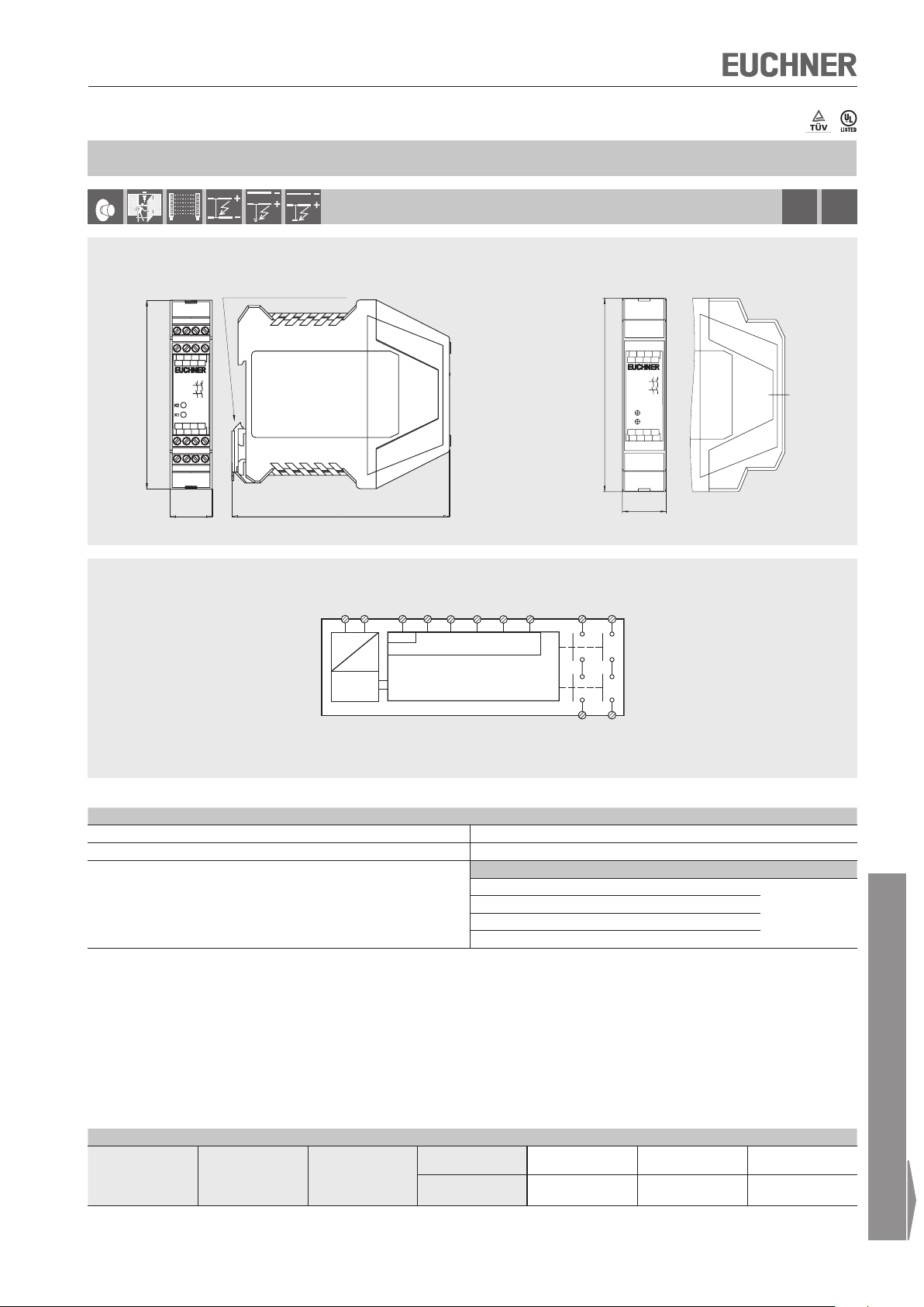
Safety relay ESM-BA2..
STOP
Dimension drawing
23 13
A1
S11 S14 S21
K1
K2
ESM-BA2
14 24
22,5
Block diagram
Suitable for 35 mm DIN rail
to DIN EN 60715 TH 35
13
23
14
24
A2
S10S13S12
ESM-BA2... ESM-BA201P
Plug-in connection terminals
please order separately
23
13
A1
S11
S14
S21
23
13
K1
K2
14
24
K2
K1
ESM-BA2
S13 S10 A2
S12
24
14
114
22,5
Cat.4STO P
0
Technical data outputs
Parameter Value
Min. switching current at DC 24 V 20 mA
Switching voltage max. DC 24 V / AC 250 V
Utilization category *
According to EN 60947-5-1
Ue = switching voltage
I
= max. switching current per contact
e
Σ
I
= max. switching current on all safety contacts (cumulative current)
e
* See page 26 for information about the utilization category
Ordering table
Series Version Outputs Version AC/DC 24 V AC 115 V AC 230 V
ESM
1) Please order plug-in connection terminals separately (see page 16)
Subject to technical modifications; no responsibility is accepted for the accuracy of this information.
BA
Safety relay
2
2 NO
Screw terminals
Plug-in
connection terminals
U
e
I
e
AC-12 250 V 6 A
AC-15 230 V 4 A
DC-12 24 V 1.25 A
DC-13 24 V 2 A
085610
ESM-BA201
097226
1)
ESM-BA201P
085611
ESM-BA202
- -
Σ I
12 A
085612
ESM-BA203
e
For technical data see page 17
9
 Loading...