

Page 1
Betriebsanleitung Schaltscharnier ESH
Bestimmungsgemäßer Gebrauch
Die Schaltscharniere ESH sind sicherheitstechnische
Einrichtungen zur Überwachung von beweglichen
trennenden Schutzeinrichtungen, wie Türen oder
Abdeckungen an Maschinen oder Anlagen.
In Verbindung mit einer trennenden Schutzeinrichtung
verhindert dieses Sicherheitsbauteil, dass gefährliche
Maschinenbewegungen ausgeführt werden, solange
die Schutzeinrichtung geöffnet ist. Wenn die Schutzeinrichtung während der gefährlichen Maschinenfunktion geöffnet wird, wird ein Halt-Befehl ausgelöst.
Die Sicherheitsschalter der Typenreihe ESH entsprechen den Vorschriften EN 60947-5-1 Anhang K und
erfüllen die Anforderungen der Berufsgenossenschaften für Maschinen, Anlagen und Personenschutz.
Vor dem Einsatz von Sicherheitsschaltern ist eine Risikobeurteilung an der Maschine durchzuführen nach
f EN ISO 13849-1, Sicherheitsbezogene Teile von
Steuerungen
f EN ISO 14121, Sicherheit von Maschinen, Risiko-
beurteilung
f IEC 62061, Sicherheit von Maschinen - Funktionale
Sicherheit sicherheitsbezogener elektrischer, elektronischer und programmierbarer elektronischer
Steuerungssysteme.
Zum bestimmungsgemäßen Gebrauch gehört das
Einhalten der einschlägigen Anforderungen für den
Einbau und Betrieb, insbesondere
f EN ISO 13849-1, Sicherheitsbezogene Teile von
Steuerungen
f EN 1088, Verriegelungseinrichtungen in Verbindung
mit trennenden Schutzeinrichtungen
f EN 60 204-1, Elektrische Ausrüstung von Ma-
schinen.
Wichtig:
f Der Anwender trägt die Verantwortung für die Ein-
bindung des Geräts in ein sicheres Gesamtsystem.
Dazu muss das Gesamtsystem z.B. nach EN ISO
13849-2 validiert werden.
f Wird zur Validierung das vereinfachte Verfahren
nach Abschnitt 6.3 EN ISO 13849-1:2008 benutzt,
reduziert sich möglicherweise der Performance
Level (PL), wenn mehrere Geräte hintereinander
geschaltet werden.
f Liegt dem Produkt ein Datenblatt bei, gelten die
Angaben des Datenblatts, falls diese von der Betriebsanleitung abweichen.
Sicherheitshinweise
Sicherheitsschalter erfüllen eine Personenschutzfunktion. Unsachgemäßer Einbau oder Manipulationen können zu schweren Verletzungen von Personen
führen.
Sicherheitsbauteile dürfen nicht umgangen (Kon-
takte überbrückt), weggedreht, entfernt oder auf
andere Weise unwirksam gemacht werden.
Beachten Sie hierzu insbesondere die Maßnahmen
zur Verringerung der Umgehungsmöglichkeiten aus
EN 1088:1995+A2:2008, Abschn. 5.7.
Ein komplettes sicherheitsgerichtetes System
besteht in der Regel aus mehreren Meldegeräten, Sensoren, Auswerteeinheiten und Konzepten
für sichere Abschaltungen. Der Hersteller einer
Maschine oder Anlage ist für die korrekte und
sichere Gesamtfunktion verantwortlich.
Montage, elektrischer Anschluss und Inbe-
triebnahme ausschließlich durch autorisiertes
Fachpersonal.
Montage
Sicherheitsschalter müssen so angeordnet sein,
dass sie gegen eine Veränderung ihrer Position
ausreichend gesichert sind.
Die angegebene maximale Belastbarkeit darf nicht
überschritten werden.
Das Schaltscharnier darf nicht als mechanische Begrenzung des Türschwenkradius verwendet werden.
Passende Leerscharniere erhalten Sie bei EUCHNER
unter der Bestell-Nr. 096 007.
Um diese Anforderungen zu erfüllen:
f müssen die Befestigungselemente zuverlässig
sein und zum Zweck ihres Lösens ein Werkzeug
erfordern.
f Sicherheitsschalter formschlüssig anbauen.
f Schalter mit Schrauben M6 anbauen.
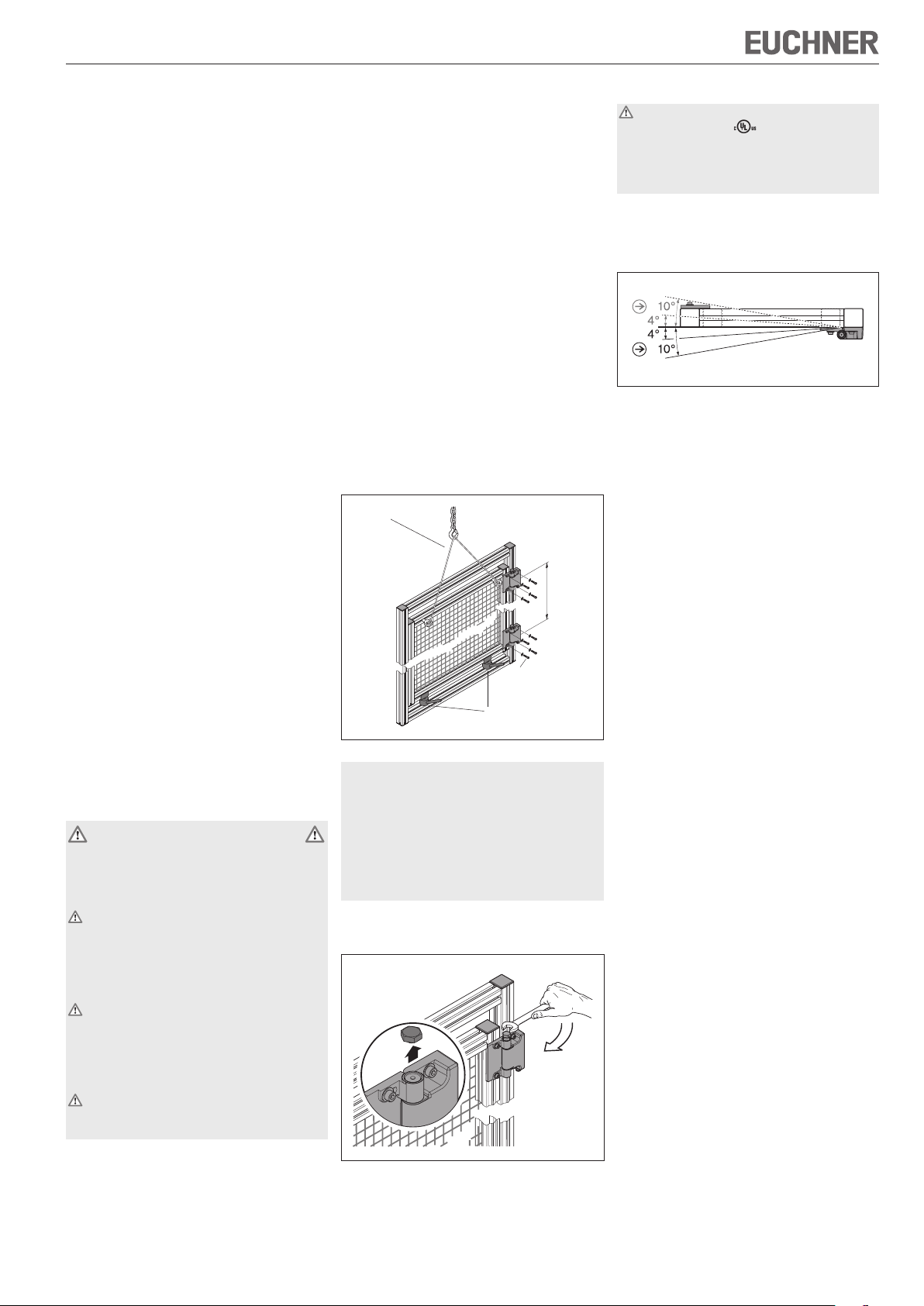
Gehen Sie folgendermaßen vor:
1. Scharniere am Rahmen befestigen. Die Befestigungspunkte der beiden Scharniere müssen
dabei soweit wie möglich auseinander liegen. Die
Schwenkachsen der Scharniere müssen genau
an einer Linie ausgerichtet werden.
2. Tür an die gewünschte Position bewegen und
gegen Abrutschen oder Herunterfallen sichern.
3. Tür an den Scharnieren montieren.
Sicherung
l = max.
4 x M6
Sicherung/Justierhilfe
4. Tür in geschlossener Stellung fixieren.
Warnung: Verletzungsgefahr durch Abrutschen
oder Sturz beim Abreißen des Sechskantkopfes.
Für sicheren Stand sorgen und Sechskantkopf nicht
ruckartig anziehen.
Vorsicht: Tür während dem Anziehen der Abrissschraube nicht bewegen, da sich dadurch der
Schaltpunkt verändert. Der Schaltpunkt wird bereits
beim Festziehen fixiert. Nachträgliches Korrigieren
ist nicht möglich.
5. Abrissschraube bis zum Anschlag einschrauben.
Langsam weiter anziehen, bis der Sechskantkopf
abreißt.
Elektrischer Anschluss
Für den Einsatz und die Verwendung gemäß den
Anforderungen von
muss eine class 2 Spannungsversorgung oder ein class 2 Transformator
nach UL1310 oder UL1585 verwendet werden.
Alternativ kann eine Kleinspannungsversorgung
nach UL508 Tabelle 32.1 verwendet werden.
f Steckverbinder M12/5-polig anschließen.
f Passende Anschlussleitungen erhalten Sie bei
EUCHNER unter der Bestell-Nr. 073461.
Inbetriebnahme
f Mechanische Funktionsprüfung
1. Tür öffnen und Schaltpunkt prüfen. Spätestens
nach einer Abweichung um 4° von der geschlossenen Stellung (Fixierstellung) muss das
Schaltscharnier schalten. Die Zwangsöffnung der
Schaltkontakte erfolgt nach ca. 10°.
2. Prüfen, ob die Tür leichtgängig ist.
f Elektrische Funktionsprüfung
1. Schutzeinrichtung schließen.
2. Maschine starten.
3. Kontrollieren, ob die Maschine beim Öffnen der
Schutzeinrichtung stoppt.
4. Maschine ausschalten.
5. Schutzeinrichtung öffnen. Maschine darf bei
geöffneter Schutzeinrichtung nicht starten!
Bei geöffneter Schutzeinrichtung muss der Sicherheitsschalter in jeder Stellung der Schutzeinrichtung
betätigt sein.
Schutz vor Umgebungseinflüssen
Voraussetzung für eine dauerhafte und einwandfreie
Sicherheitsfunktion ist der Schutz vor eindringenden
Fremdkörpern wie Spänen, Sand, Strahlmitteln usw.
Zur Reinigung der Sicherheitsschalter nur lösungsmittelfreie und säurefreie Reinigungsmittel verwenden!
Kontrolle und Wartung
Wartungsarbeiten sind nicht erforderlich. Um eine einwandfreie und dauerhafte Funktion zu gewährleisten,
sind regelmäßige Kontrollen erforderlich auf
f einwandfreie Schaltfunktion
f sichere Befestigung der Bauteile
f Ablagerungen und Verschleiß
f gelockerte Steckverbinder.
Bei Beschädigung oder Verschleiß muss der gesamte
Schalter ausgetauscht werden. Der Austausch von
Einzelteilen oder Baugruppen ist unzulässig!
Hinweis: Das Baujahr ist in der unteren, rechten Ecke
des Typenschilds ersichtlich.
Haftungsausschluss bei
f nicht bestimmungsgemäßem Gebrauch
f Nichteinhalten der Sicherheitshinweise
f Anbau und elektrischem Anschluss durch nicht
autorisiertes Fachpersonal.
f nicht durchgeführten Funktionskontrollen.
Funktion
Der Sicherheitsschalter meldet, dass die Schutzeinrichtung geschlossen ist.
Im Sichtfenster wird zusätzlich der Schaltzustand
angezeigt (Auslieferungszustand closed).
Durch den Schalter erfolgt keine Zuhaltung!
¨ Der Schaltpunkt ist in dieser Stellung dauerhaft
fixiert.
Page 2
Betriebsanleitung Schaltscharnier ESH
1
4
5
2
3
1
4
5
2
3
EG-Konformitätserklärung
Der nachstehende Hersteller erklärt hiermit, dass
das Produkt in Übereinstimmung ist mit den Bestimmungen der nachfolgend aufgeführten Richtlinie(n)
und dass die jeweiligen Normen zur Anwendung
gelangt sind.
EUCHNER GmbH + Co. KG
Kohlhammerstraße 16
70771 Leinfelden-Echterdingen, Deutschland
Angewendete Richtlinien:
f Maschinenrichtlinie 2006/42/EG
Angewendete Normen:
f EN 60947-5-1:2004 + Cor.:2005 + A1:2009
f EN 1088:1995+A2:2008
Leinfelden, Juli 2010
Dipl.-Ing. Michael Euchner
Geschäftsführer
Duc Binh Nguyen
Dokumentationsbevollmächtigter
Die unterzeichnete EG-Konformitätserklärung ist dem
Produkt beigelegt.
Technische Daten
Parameter Wert
Gehäusewerkstoff Zinkdruckguss
Schutzart nach IEC 60529 IP 67
Mech. Schaltspiele 1x10
Umgebungstemperatur -25 °C … +70 °C
Verschmutzungsgrad
(extern, nach EN 60947)
Einbaulage beliebig
Masse 0,77 kg
Belastbarkeit gemäß Lebens-
dauertest nach EN 1935
Schwenkwinkel -10° … 180°
Schaltpunkt 4° ab Fixierpunkt
Zwangsöffnung ca. 10° ab Fixierpunkt
Betätigungshäufigkeit max. 1200 Schaltspiele / h
Schaltprinzip Sprungschaltglied
Kontaktwerkstoff Silberlegierung
Anschlussart Steckverbinder M12 / 5-polig
Bemessungsstoßspannungs-
festigkeit
Bemessungsisolationsspan-
nung
Bedingter Kurzschlussstrom 100 A
Gebrauchskategorie nach EN 60947-5-1
AC-15
DC-13
Schaltstrom min. bei 24V 1 mA
Kurzschlussschutz
(Steuersicherung) nach
IEC 60269 -1
Konventioneller thermischer
Strom I
th
Zuverlässigkeitswerte nach EN ISO 13849-1
B10d 2 x 10
6
3 (Industrie)
Bandklasse 12
(100 kg Türgewicht)
2,5 kV
60 V
1,5 A 30 V
2,0 A 24 V
2 A gG
3 A
6
Ausführung
ESH-PRO-20A-1205
Ausführung
ESH-PRO-11A-1205
Technische Änderungen vorbehalten, alle Angaben ohne Gewähr. © EUCHNER GmbH + Co. 096772-07-11/12 (Originalbetriebsanleitung)
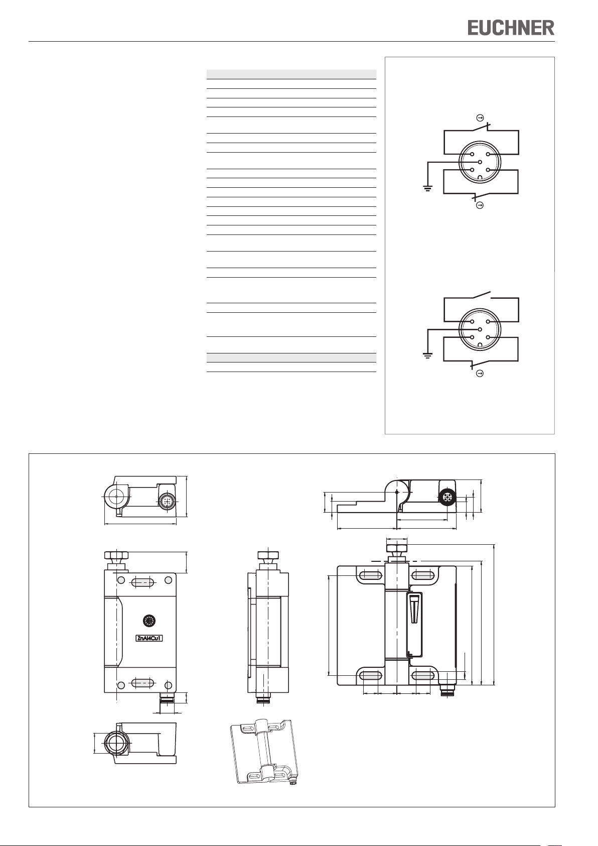
Bild 1: Pinbelegung Stecker M12/5-polig
Abmessungen Lieferzustand Abmessungen Schaltpunkt fixiert
34
60
18
17
9,4
50 50
42,5
SW
17
84
(4x)
6,5
27,4
12,9
8,9
max. 120
100
104
9
M12x1
SW17
1612 16 12
Bild 2: Maßzeichnung Schaltscharnier ESH
EUCHNER GmbH + Co. KG Kohlhammerstraße 16 D-70771 Leinfelden-Echterdingen Tel. +49/711/75 97-0 Fax +49/711/75 33 16 www.euchner.de info@euchner.de
Page 3
Operating Instructions Safety Hinge ESH
Correct use
The safety hinges ESH are safety devices for monitoring movable safety guards, such as doors or covers
on machinery or systems.
In combination with a separating safety guard, this
safety component prevents the safety guard from
being opened while a dangerous machine movement
is being performed. A stop command is triggered if
the safety guard is opened during the dangerous
machine function.
The safety switches series ESH comply with the
regulations of EN 60947-5-1, Annex K and comply
with the requirements of the employers' liability insurance associations for machines, installations and
personnel protection.
Before safety switches are used, a risk assessment
must be performed on the machine in accordance
with
f EN ISO 13489-1, Safety of machinery. Safety re-
lated parts of control systems. General principles
for design
f EN ISO 14121, Safety of machinery. Risk assess-
ment. Principles
f IEC 62061, Safety of machinery. Functional safety
of safety-related electrical, electronic and programmable electronic control systems.
Correct use includes compliance with the relevant requirements for installation and operation, in particular
f EN ISO 13489-1, Safety of machinery. Safety re-
lated parts of control systems. General principles
for design
f EN 1088, Safety of machinery. Interlocking devices
associated with guards. Principles for design and
selection
f EN 60 204-1, Safety of machinery. Electrical equip-
ment of machines. General requirements.
Important:
f The user is responsible for the integration of the
device in a safe overall system. For this purpose
the overall system must be validated, e.g. in accordance with EN ISO 13849-2.
f If the simplified method according to section 6.3
EN ISO 13849-1:2008 is used for validation, the
Performance Level (PL) may be reduced if several
devices are connected one after the other.
f If a product data sheet is included with the product,
the information on the data sheet applies in case
of discrepancies with the operating instructions.
Safety precautions
Safety switches fulfill a personal protection function.
Incorrect installation or tampering can lead to severe
injuries to personnel.
Safety components must not be bypassed
(bridging of contacts), turned away, removed
or otherwise rendered ineffective.
On this topic pay attention in particular to the measures for reducing the possibility of bypassing from
EN 1088:1995+A2:2008, sec. 5.7.
A complete safety-oriented system generally
consists of several signaling devices, sensors,
evaluation units and concepts for safe shutdown.
The manufacturer of a machine or installation is
responsible for correct and safe overall function.
Mounting, electrical connection and setup only
by authorized personnel.
Function
The safety switch signals that the safety guard is
closed.
The switching state is additionally indicated in the
window (default setting on delivery closed).
The switch does not perform guard locking!
Installation
Safety switches must be arranged such that they are
adequately secured against movement.
The maximum load given must not be exceeded.
The safety hinge is not allowed to be used as a
mechanical limit for the door pivot radius.
You can obtain suitable plain hinges without switches
from EUCHNER under order no. 096 007.
To meet these requirements:
f The fixings must be reliable and must also require
the use of a tool to undo them.
f Mount the safety switch positively.
f Fit switches using M6 screws.
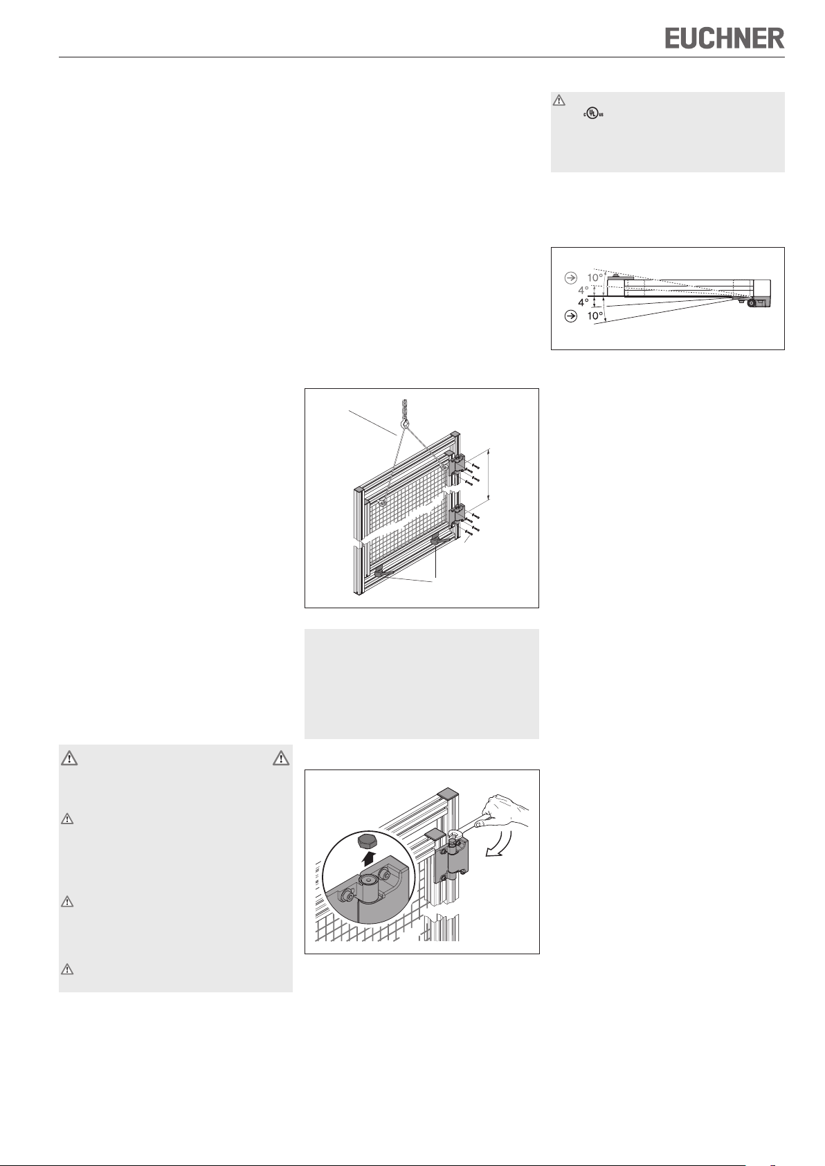
Proceed as follows:
1. Fasten hinges to the frame. The fastening points
for the two hinges must be as far apart as possible. The axes around which the hinges pivot
must be exactly in a line.
2. Move door to the required position and secure
against slipping or falling.
3. Fit door to the hinges.
Support
l = max.
4 x M6
Support/adjustment aid
4. Fix door in closed position.
Warning: risk of injury due to slipping or falling on
shearing off the hex head. Ensure you are standing
safely and do not tighten hex head with a jerking
action.
Caution: do not move door while tightening the
shear screw, as then the operating point will change.
The operating point is already fixed on tightening. It
is not possible to correct the position later.
5. Screw in shear screw to the stop. Slowly tighten
further until the hex head shears off.
¨ The operating point is fixed permanently in this
position.
Electrical connection
For use and applications as per the requirements
of
, a class 2 power supply or a class 2
transformer according to UL1310 or UL1585
must be used. As an alternative, a low voltage
power supply according to UL508 table 32.1
can be used.
f Connect M12/5-pin plug connector.
f You can obtain suitable connection cables from
EUCHNER under order no. 073461.
Setup
f Mechanical function test
1. Open door and check operating point. The hinge
must switch at the latest 4° from the closed position (fixing position). The switching contacts are
positively opened after approx. 10°.
2. Check whether the door moves freely.
f Electrical function test
1. Close the safety guard.
2. Start the machine.
3. Check whether the machine stops when the
safety guard is opened.
4. Switch off the machine.
5. Open the safety guard. The machine must not
start when the safety guard is open!
When the safety guard is open, the safety switch must
be actuated in any safety guard position.
Protection against environmental effects
A lasting and correct safety function requires protection against the penetration of foreign bodies
such as swarf, sand, blasting shot, etc. Only use
solvent-free and acid-free cleaning agents to clean
the safety switch!
Inspection and service
No servicing is required. but regular inspection of
the following is necessary to ensure trouble-free
long-term operation:
f correct switching function
f secure mounting of components
f dirt and wear
f loose plug connectors.
If damage or wear is found, the complete switch
must be replaced. Replacement of individual parts
or assemblies is not permitted!
Note: The year of manufacture can be seen in the
bottom, right corner of the rating plate.
Exclusion of liability under the following
circumstances
f incorrect use
f non-compliance with safety regulations
f installation and electrical connection not performed
by authorized personnel
f failure to perform functional checks.
Page 4

Operating Instructions Safety Hinge ESH
1
4
5
2
3
1
4
5
2
3
EC declaration of conformity
The manufacturer named below herewith declares
that the product fulfills the provisions of the
directive(s) listed below and that the related standards
have been applied.
EUCHNER GmbH + Co. KG
Kohlhammerstraße 16
70771 Leinfelden-Echterdingen, Germany
Directives applied:
f Machinery directive 2006/42/EC
Standards applied:
f EN 60947-5-1:2004 + Cor.:2005 + A1:2009
f EN 1088:1995+A2:2008
Leinfelden, July 2010
Dipl.-Ing. Michael Euchner
Director
Duc Binh Nguyen
Authorized representative empowered to draw up
documentation
The signed EC declaration of conformity is included
with the product.
Technical data
Parameter Value
Housing material Die-cast zinc
Degree of protection according
to IEC 60529
Mechanical operating cycles 1x10
Ambient temperature -25 °C ... +70 °C
Degree of contamination
(external, acc. to EN 60947)
Installation position Any
Weight 0.77 kg
Max. load as per mechanical
life test acc. to EN 1935
Pivoting angle -10° … 180°
Operating point 4° from fixing point
Positively driven Approx. 10° from fixing point
Actuation frequency Max. 1200 operating cycles / h
Switching principle Snap-action switching contact
Contact material Silver alloy
Connection type Plug connector M12 / 5-pin
Rated impulse withstand
voltage
Rated insulation voltage 60 V
Rated short-circuit current 100 A
Utilization category to EN 60947-5-1
AC-15
DC-13
Switching current, min., at 24V 1 mA
Short circuit protection (control
circuit fuse)
acc. to IEC 60269-1
Conventional thermal current I
Reliability figures according to EN ISO 13849-1
B10d 2 x 10
IP 67
6
3 (industrial)
Grade 12
(100 kg door weight)
2.5 kV
1.5 A 30 V
2.0 A 24 V
2 A gG
3 A
th
6
Version
ESH-PRO-20A-1205
Version
ESH-PRO-11A-1205
Figure 1: Pin assignment plug M12/5-pin
Dimensions as supplied Dimensions operating point fixed
34
60
18
17
9,4
50 50
42,5
SW
17
84
(4x)
6,5
27,4
12,9
8,9
Subject to technical modifications; no responsibility is accepted for the accuracy of this information. © EUCHNER GmbH + Co. 096772-07-11/12 (translation of the original operating instructions)
max. 120
100
104
9
M12x1
SW17
1612 16 12
Figure 2: Dimension drawing safety hinge ESH
EUCHNER GmbH + Co. KG Kohlhammerstraße 16 D-70771 Leinfelden-Echterdingen Tel. +49/711/75 97-0 Fax +49/711/75 33 16 www.euchner.de info@euchner.de
Page 5
Mode d’emploi pour les charnières ESH
Utilisation conforme
Les charnières ESH sont des dispositifs de sécurité pour la surveillance des protecteurs mobiles
comme des portes ou des carters de machines ou
d’installations.
Utilisé avec un protecteur, ce composant de sécurité
interdit tout mouvement dangereux de la machine
tant que le protecteur est ouvert. Un ordre d’arrêt
est émis en cas d’ouverture du protecteur pendant
le fonctionnement dangereux de la machine.
Les interrupteurs de sécurité de la série ESH répondent aux prescriptions EN 60947-5-1 Annexe K et
satisfont aux exigences des organismes professionnels concernant les machines, les installations et la
protection des personnes.
Avant d'utiliser des interrupteurs de sécurité, il est
nécessaire d'effectuer une analyse d'appréciation du
risque sur la machine selon
f EN ISO 13849-1, Parties des systèmes de com-
mande relatives à la sécurité
f EN ISO 14121, Sécurité des machines, appréciation
du risque
f IEC 62061, Sécurité des machines – Sécurité fonc-
tionnelle des systèmes de commande électriques,
électroniques et électroniques programmables
relatifs à la sécurité.
Pour que l’utilisation soit conforme, les instructions
applicables au montage et à la mise en service
doivent être respectées, en particulier
f EN ISO 13849-1, Parties des systèmes de com-
mande relatives à la sécurité
f EN 1088, Dispositifs de verrouillage associés à
des protecteurs
f EN 60 204-1, Equipement électrique des machines.
Important :
f L'utilisateur est responsable de l'intégration de
l'appareil dans un système global sécurisé. Ce
dernier doit être validé à cet effet, par ex. selon
EN ISO 13849-2.
f Si la validation fait appel à la procédure simplifiée
selon le paragraphe 6.3 EN ISO 13849-1:2008,
le niveau de performance ou Performance Level
(PL) peut diminuer lorsque plusieurs appareils sont
raccordés en série l'un à la suite de l'autre.
f Si le produit est accompagné d'une fiche technique,
les indications de cette dernière prévalent en cas
de différences avec les indications figurant dans le
mode d'emploi.
Consignes de sécurité
Les interrupteurs de sécurité remplissent une fonction de protection des personnes. Le montage ou
les manipulations non conformes peuvent engendrer
de graves blessures.
Les éléments de sécurité ne doivent pas être
contournés (pontage des contacts), déplacés,
retirés ou être inactivés de quelque manière que
ce soit.
Tenez compte en particulier des mesures de
réduction des possibilités de fraude selon
EN 1088:1995+A2:2008, paragr. 5.7.
Un système complet dédié à la sécurité se
compose généralement de plusieurs appareils
de signalisation, de capteurs, d'unités d'analyse
et de concepts pour la mise hors service sûre.
Le fabricant d'une machine ou d'une installation
est responsable du fonctionnement correct et
sûr de l'ensemble.
Montage, raccordement électrique et mise en
service exclusivement par un personnel habilité.
Fonction
L’interrupteur de sécurité signale que le protecteur
est fermé.
La fenêtre indique en outre la position de commutation
(état d’origine : closed).
L'interrupteur n'actionne aucun système d'interverrouillage !
Montage
Les interrupteurs de sécurité doivent être disposés
de manière à éviter toute modification involontaire
de leur position.
La charge admissible maximale indiquée ne doit pas
être dépassée.
La charnière ne doit pas être utilisée pour limiter
mécaniquement le rayon de pivotement de la porte.
Les charnières correspondantes ne faisant pas office
d'interrupteur de sécurité sont disponibles auprès
d’EUCHNER, sous le numéro de commande 096 007.
Pour remplir ces conditions :
f Les éléments de fixation doivent être fiables et
leur dévissage ne doit pouvoir être effectué qu’à
l’aide d’un outil ;
f Fixer l'interrupteur de sécurité de façon perma-
nente.
f Monter l’interrupteur à l’aide de vis M6.
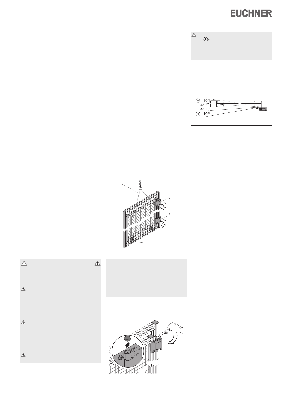
Procédez de la manière suivante :
1. Fixer les charnières au cadre. La distance entre
les points de fixation des deux charnières doit
alors être aussi importante que possible. Les
axes de pivotement des charnières doivent être
alignés avec précision.
2. Placer la porte dans la position souhaitée et la
protéger contre les glissements et les chutes.
3. Monter la porte sur les charnières.
Dispositif de sécurité
l = max.
4 x M6
Dispositif de sécurité
/ Auxiliaire d’ajustage
4. Fixer la porte en position fermée.
Avertissement : Risque de blessures causées par
un glissement ou une chute en cas de rupture de la
tête hexagonale. S’assurer que la position est sûre
et serrer la tête hexagonale de manière continue.
Attention : Ne pas bouger la porte lors du serrage
de la vis autocassante ou le point d’action sera modifié. Le point d’action est fixé dès le serrage. Il est
impossible de le corriger ultérieurement.
5. Visser la vis autocassante jusqu’à la butée.
Continuer de visser doucement jusqu’à ce que
la tête hexagonale se brise.
¨ Dans cette position, le point d’action est fixé de
manière définitive.
Raccordement électrique
Pour que l’utilisation soit conforme aux exigences
de
, une alimentation ou un transformateur
de classe 2 doit être utilisé conformément à
UL1310 ou UL1585. Une source d'alimentation
basse tension conforme à la norme UL508
Tableau 32.1 peut également être utilisée.
f Brancher le connecteur M12 à 5 broches.
f Les câbles de raccordement correspondants sont
disponibles auprès d’EUCHNER sous le numéro de
commande 073461.
Mise en service
f Contrôle du fonctionnement mécanique
1. Ouvrir la porte et vérifier le point d’action. La
charnière doit transmettre un signal au plus tard
après un écart de 4° par rapport à la position
fermée (position de fixation). L’ouverture positive
des contacts se produit après environ 10°.
2. Vérifier que la porte s’ouvre et se ferme facilement.
f Contrôle du fonctionnement électrique
1. Fermer le protecteur.
2. Démarrer la machine.
3. Contrôler si la machine s'arrête lors de l'ouverture du protecteur.
4. Eteindre la machine.
5. Ouvrir le protecteur. La machine ne doit pas
démarrer lorsque le protecteur est ouvert !
Lorsque le protecteur est ouvert, l’interrupteur de
sécurité doit être actionné dans chacune des positions du protecteur.
Protection contre les influences ambiantes
La condition pour garantir une fonction de sécurité
durable et parfaite est de protéger le système contre
la pénétration de corps étrangers (ex. copeaux, sable,
grenailles, etc.). Pour le nettoyage des interrupteurs
de sécurité, utiliser uniquement des produits de
nettoyage exempts de solvants et d’acide !
Contrôle et entretien
Aucun entretien n'est nécessaire. Pour garantir un
fonctionnement irréprochable et durable, il convient
toutefois de vérifier régulièrement les points suivants :
f Fonction de commutation correcte
f Bonne fixation des composants
f Dépôts et usure
f Serrage des connecteurs.
En cas d'endommagement ou d'usure, il est nécessaire de remplacer entièrement l'interrupteur. Le
remplacement de composants ou de sous-ensembles
n'est pas autorisé !
Remarque : l'année de construction figure dans le
coin inférieur droit de la plaque signalétique.
Nous déclinons toute responsabilité
f en cas d’utilisation non conforme ;
f en cas de non-respect des consignes de sécurité ;
f si le montage et le raccordement électrique sont
effectués par du personnel non agréé.
f si les contrôles fonctionnels ne sont pas effectués.
Page 6

Mode d’emploi pour les charnières ESH
1
4
5
2
3
1
4
5
2
3
Déclaration de conformité CE
Le fabricant ci-dessous déclare par la présente que
le produit est conforme aux dispositions de la ou des
directive(s) précisées ci-après ainsi qu’aux normes qui
lui sont applicables.
EUCHNER GmbH + Co. KG
Kohlhammerstraße 16
D-70771 Leinfelden-Echterdingen, Allemagne
Directives utilisées :
f Directive Machines 2006/42/CE
Normes utilisées :
f EN 60947-5-1:2004 + Cor.:2005 + A1:2009
f EN 1088:1995+A2:2008
Leinfelden, juillet 2010
Dipl.-Ing. Michael Euchner
Directeur Général
Duc Binh Nguyen
Responsable documentation
La déclaration de conformité CE signée est jointe
au produit.
Caractéristiques techniques
Paramètre Valeur
Matériau du boîtier Zinc moulé sous pression
Indice de protection selon
IEC 60529
Manœuvres mécaniques 1x10
Température ambiante -25 °C … +70 °C
Degré de pollution
(externe, selon EN 60947)
Position de montage Au choix
Masse 0,77 kg
Charge admissible conformé-
ment à l’essai de durée de vie
selon la norme EN 1935
Angle de pivotement -10° … 180°
Point d’action 4° à partir du point de fixation
Ouverture positive Environ 10 ° à partir du point
Fréquence d’actionnement Maxi. 1 200 manoeuvres / h
Principe de commutation Élément de contact à action
Matériau des contacts Alliage argent
Type de raccordement Connecteur M12 à 5 broches
Tension nominale d’essai
(impulsion)
Tension nominale d’isolement 60 V
Courant conditionnel de
court-circuit
Catégorie d'emploi selon EN 60947-5-1
AC-15
DC-13
Pouvoir de coupure min. à 24V 1 mA
Protection contre les courts-
circuits (fusible de commande)
selon IEC 60269-1
Courant thermique conventionnel I
th
Valeurs de fiabilité selon EN ISO 13849-1
B10d 2 x 10
IP 67
6
3 (industrie)
Classe 12
(poids de la porte 100 kg)
de fixation
brusque
2,5 kV
100 A
1,5 A 30 V
2,0 A 24 V
2 A gG
3 A
6
Version
ESH-PRO-20A-1205
Version
ESH-PRO-11A-1205
Figure 1 : Affectation des broches du connecteur M12
Sous réserve de modifications techniques, indications non contractuelles. © EUCHNER GmbH + Co. 096772-07-11/12 (trad. mode d'emploi d'origine)
à 5 broches
Dimensions à l’état de
livraison
34
60
18
17
9,4
50 50
84
9
M12x1
Dimensions après fixation du
point d’action
42,5
SW
17
1612 16 12
(4x)
6,5
27,4
12,9
8,9
max. 120
100
104
SW17
Figure 2 : Dimensions de la charnière ESH
EUCHNER GmbH + Co. KG Kohlhammerstraße 16 D-70771 Leinfelden-Echterdingen Tél. +49/711/75 97-0 Fax +49/711/75 33 16 www.euchner.de info@euchner.de
Page 7

Istruzioni di impiego finecorsa a cerniera ESH
Impiego conforme alla destinazione d'uso
I finecorsa ESH sono dispositivi di sicurezza per il
controllo dei ripari mobili di protezione quali porte o
coperture applicate su macchine o impianti.
In combinazione con un riparo, questo componente
di sicurezza impedisce i movimenti pericolosi della
macchina quando il riparo è aperto. Se, durante una
funzione pericolosa della macchina, il riparo di protezione viene aperto si genera un ordine di arresto.
I finecorsa di sicurezza della serie ESH sono conformi alle prescrizioni dell'allegato K della norma
EN 60947-5-1 e ai requisiti previsti dagli istituti
di assicurazione contro gli infortuni sul lavoro per
macchine, impianti e protezione delle persone.
Prima di impiegare i finecorsa di sicurezza, la macchina deve essere stata oggetto di una valutazione
del rischio, conformemente alle norme:
f EN ISO 13849-1, Parti dei sistemi di comando
legate alla sicurezza.
f EN ISO 14121, Sicurezza del macchinario, Valuta-
zione del rischio
f IEC 62061, Sicurezza del macchinario – Sicurezza
funzionale dei sistemi di comando e controllo elettrici, elettronici ed elettronici programmabili correlati
alla sicurezza.
L'impiego conforme alla destinazione d'uso implica
il rispetto delle vigenti norme relative all'installazione
e all'esercizio, in particolare
f EN ISO 13849-1, Parti dei sistemi di comando
legate alla sicurezza.
f EN 1088, Dispositivi di interblocco associati ai ripari
f EN 60.204-1, Equipaggiamento elettrico delle
macchine.
Importante:
f l'utente è responsabile per l'integrazione del di-
spositivo in un sistema generale sicuro. A questo
scopo, il sistema generale deve essere validato p.
es. secondo la EN ISO 13849-2.
f Se per la validazione si ricorre alla procedura
semplificata secondo la sezione 6.3 della
EN ISO 13849:2008, si ridurrà eventualmente il
Performance Level (PL) se vengono collegati in
serie più dispositivi.
f Se al prodotto è allegata una scheda tecnica, valgono
le indicazioni della stessa, qualora fossero diverse da
quanto riportato nelle istruzioni di impiego.
Avvertenze di sicurezza
I finecorsa di sicurezza svolgono una funzione di
protezione delle persone. Un'installazione inadeguata
o eventuali manomissioni possono causare gravi
lesioni alle persone.
I componenti di sicurezza non devono essere né
aggirati (ponticellando i contatti), né rimossi, né
girati, né resi inefficaci in altra maniera.
Osservare in proposito le misure per la riduzione delle possibilità di manomissione secondo la
EN 1088:1995+A2:2008, sezione 5.7.
Un sistema di sicurezza completo è costituito
normalmente da diversi dispositivi di segnalazione, sensori, centraline di elaborazione e schemi
per garantire l'arresto sicuro. Il costruttore di una
macchina o di un impianto è responsabile anche
del corretto e sicuro utilizzo degli stessi.
L'installazione, il collegamento elettrico e la mes-
sa in servizio sono da affidare esclusivamente al
personale specializzato e autorizzato.
Funzionamento
Il finecorsa di sicurezza segnala la chiusura del riparo
di protezione.
Nella finestra di ispezione viene indicato inoltre lo
stato di commutazione (alla consegna closed).
Il finecorsa non effettua il bloccaggio del riparo!
Installazione
I finecorsa di sicurezza devono essere installati
in modo che non siano possibili variazioni della
posizione.
Il carico ammissibile max. prescritto non deve essere
superato.
Il finecorsa a cerniera non deve essere utilizzato
come impedimento meccanico del raggio di rotazione
della porta.
Cerniere passive adatte sono disponibili presso la
EUCHNER con il numero d'ordine 096 007.
Per soddisfare queste condizioni è necessario attenersi a quanto segue:
f Gli elementi di fissaggio devono essere sicuri e per
essere allentati deve essere necessario utilizzare
un attrezzo.
f Installare il finecorsa di sicurezza con un corretto
accoppiamento meccanico.
f Installare il finecorsa con viti M6.
Procedere come specificato di seguito:
1. Fissare le cerniere al telaio. I punti di fissaggio
delle due cerniere devono essere posizionati alla
massima distanza possibile l'uno dall'altro. Gli
assi di rotazione delle cerniere devono essere
allineati esattamente su una linea.
2. Spostare il riparo nella posizione desiderata e
bloccarlo in modo da evitarne lo scivolamento
o la discesa.
3. Montare il riparo sulle cerniere.
Fissaggio
l = max.
4 x M6
Fissaggio/Dispositivo
di regolazione
4. Fissare il riparo nella posizione di chiusura.
Attenzione: pericolo di lesioni dovuto allo scivolamento o alla caduta in caso di rottura della testa
esagonale. Accertarsi della posizione sicura e non
serrare la testa esagonale in modo brusco.
Attenzione: non muovere il riparo durante la fase
di serraggio della vite a strappo, ciò potrebbe
modificare il punto di scatto. Il punto di scatto viene
fissato già al momento del serraggio. Non è possibile
effettuare la regolazione successivamente.
5. Avvitare fino all'arresto la vite a strappo. Continuare a serrare lentamente fino allo strappo della
testa esagonale.
¨ Il punto di scatto è fissato in modo permanente
in questa posizione.
Collegamento elettrico
Per l'impiego e l'utilizzo in conformità ai requisiti
utilizzare l'alimentazione di classe 2 o un
trasformatore di classe 2 secondo UL1310 o
UL1585. In alternativa utilizzare un'alimentazione a
bassissima tensione secondo UL508 Tabella 32.1.
f Collegare il connettore M12/5 poli.
f I cavi di collegamento adatti sono disponibili presso
la EUCHNER con il numero d'ordine 073461.
Messa in servizio
f Prova della funzione meccanica
1. Aprire il riparo e verificare il punto di scatto.
Il finecorsa a cerniera deve intervenire al più
tardi quando si raggiunge uno scostamento di
4° rispetto alla posizione di chiusura (posizione
di fissaggio). L'apertura forzata dei contatti di
commutazione avviene dopo circa 10°.
2. Verificare che il riparo sia scorrevole nei movimenti.
f Prova della funzione elettrica
1. Chiudere il riparo di protezione.
2. Avviare la macchina.
3. Verificare che l'apertura del riparo provochi
l'arresto della macchina.
4. Spegnere la macchina.
5. Aprire il riparo di protezione. Con il riparo di protezione aperto, la macchina non deve avviarsi!
Con il riparo protezione aperto, il finecorsa di sicurezza deve essere azionato in ogni posizione del riparo.
Protezione contro gli agenti ambientali
Premessa necessaria per un durevole e corretto funzionamento di sicurezza è prevenire la penetrazione
di corpi estranei quali trucioli, sabbia, graniglia e così
via. Per la pulizia dei finecorsa utilizzare esclusivamente detergenti privi di solventi e di acidi!
Controllo e manutenzione
Non sono necessari interventi di manutenzione. Per
garantire il funzionamento corretto e durevole sono
comunque necessari controlli ad intervalli regolari
in merito a
f corretta commutazione
f fissaggio dei singoli componenti
f presenza di depositi o segni d'usura
f eventuale allentarsi dei connettori.
In caso di danneggiamenti o di usura è necessario
sostituire il finecorsa di sicurezza completo. Non è
ammessa la sostituzione di singoli componenti o di
blocchi!
Avvertenza: l'anno di costruzione si trova sull'angolo
destro in basso della targhetta di identificazione.
Esclusione di responsabilità in caso di
f impiego non conforme alla destinazione
f mancato rispetto delle avvertenze di sicurezza
f montaggio e collegamento elettrico non eseguiti da
personale specializzato e autorizzato
f omissione dei controlli funzionali.
Page 8

Istruzioni di impiego finecorsa a cerniera ESH
1
4
5
2
3
1
4
5
2
3
Dichiarazione CE di conformità
Il fabbricante indicato di seguito dichiara che il prodotto è conforme alle disposizioni della/delle direttiva/e
sottoelencata/e e che sono state applicate le norme
pertinenti.
EUCHNER GmbH + Co. KG
Kohlhammerstraße 16
70771 Leinfelden-Echterdingen, Germania
Direttive applicate:
f Direttiva Macchine 2006/42/CE
Norme applicate:
f EN 60947-5-1:2004 + Cor.:2005 + A1:2009
f EN 1088:1995+A2:2008
Leinfelden, luglio 2010
Dipl. Ing. Michael Euchner
Amministratore delegato
Duc Binh Nguyen
Responsabile della documentazione
La dichiarazione CE di conformità firmata è allegata
al prodotto.
Dati tecnici
Parametro Valore
Materiale custodia zama nichelata
Grado di protezione sec.
IEC 60529
Manovre mecc. 1x10
Temperatura ambiente -25 °C … +70 °C
Grado di inquinamento
(esterno, secondo EN 60947)
Posizione di installazione qualsiasi
Peso 0,77 kg
Carico ammissibile secondo il
test di durata conforme
EN 1935
Angolo di rotazione -10° … 180°
Punto di scatto 4° dal punto di fissaggio
Apertura forzata ca. 10° dal punto di fissaggio
Frequenza di azionamento max. 1200 manovre/h
Principio di commutazione microinterruttore a scatto rapido
Materiale dei contatti lega d’argento
Tipo di collegamento connettore M12/ 5 poli
Rigidità dielettrica nominale 2,5 kV
Tensione di isolamento
nominale
Corrente di cortocircuito
condizionata
Categoria d'impiego secondo EN 60947-5-1
AC-15
DC-13
Corrente di commutazione
min. a 24V
Protezione contro cortocircuiti
(fusibile di comando) secondo
IEC 60269-1
Corrente continua termica
standard I
th
Valori di affidabilità secondo EN ISO 13849-1
B10d 2 x 10
IP 67
6
3 (industria)
classe di banda 12
(100 kg peso riparo)
60 V
100 A
1,5 A 30 V
2,0 A 24 V
1 mA
2 A gG
3 A
6
Esecuzione
ESH-PRO-20A-1205
Esecuzione
ESH-PRO-11A-1205
Fig. 1: Piedinatura connettore M12/5 poli
Dimensioni di fornitura Dimensioni del punto di scatto fissato
34
60
18
17
9,4
50 50
42,5
SW
17
27,4
12,9
8,9
max. 120
(4x)
6,5
100
104
M12x1
84
9
1612 16 12
SW17
Con riserva di modifiche tecniche, tutti i dati sono soggetti a modifiche. © EUCHNER GmbH + Co. 096772-07-11/12 (Traduzione delle istruzioni di impiego originali)
Fig. 2: Dimensioni finecorsa a cerniera ESH
EUCHNER GmbH + Co. KG Kohlhammerstraße 16 D-70771 Leinfelden-Echterdingen Tel. +49/711/75 97-0 Fax +49/711/75 33 16 www.euchner.de info@euchner.de
 Loading...